

LG LS-L1262CL, LS-L1261CLCM, LS-L1262CM, LS-L1262CN, LS-L1262CD Service Manual
...
SERVICE MANUAL
Room Air Conditioner
CAUTION
-BEFORE SERVICING THE UNIT, READ THE SAFETY
PRECAUTIONS IN THIS MANUAL.
-ONLY FOR AUTHORIZED SERVICE PERSONNEL.
MODEL : LS-L1261CL/CM/CN/CD/CS
LS-L1262CL/CM/CN/CD/CS
LS-L1263DL
LS-L1261EL/HL/HM/HN/HD/HS
LS-L1262HL/HM/HN/HD/HS
LS-L1220HL/HM/HN/HD/HS
website http://biz.LGservice.com
e-mail http://www.LGEservice.com/techsup.html

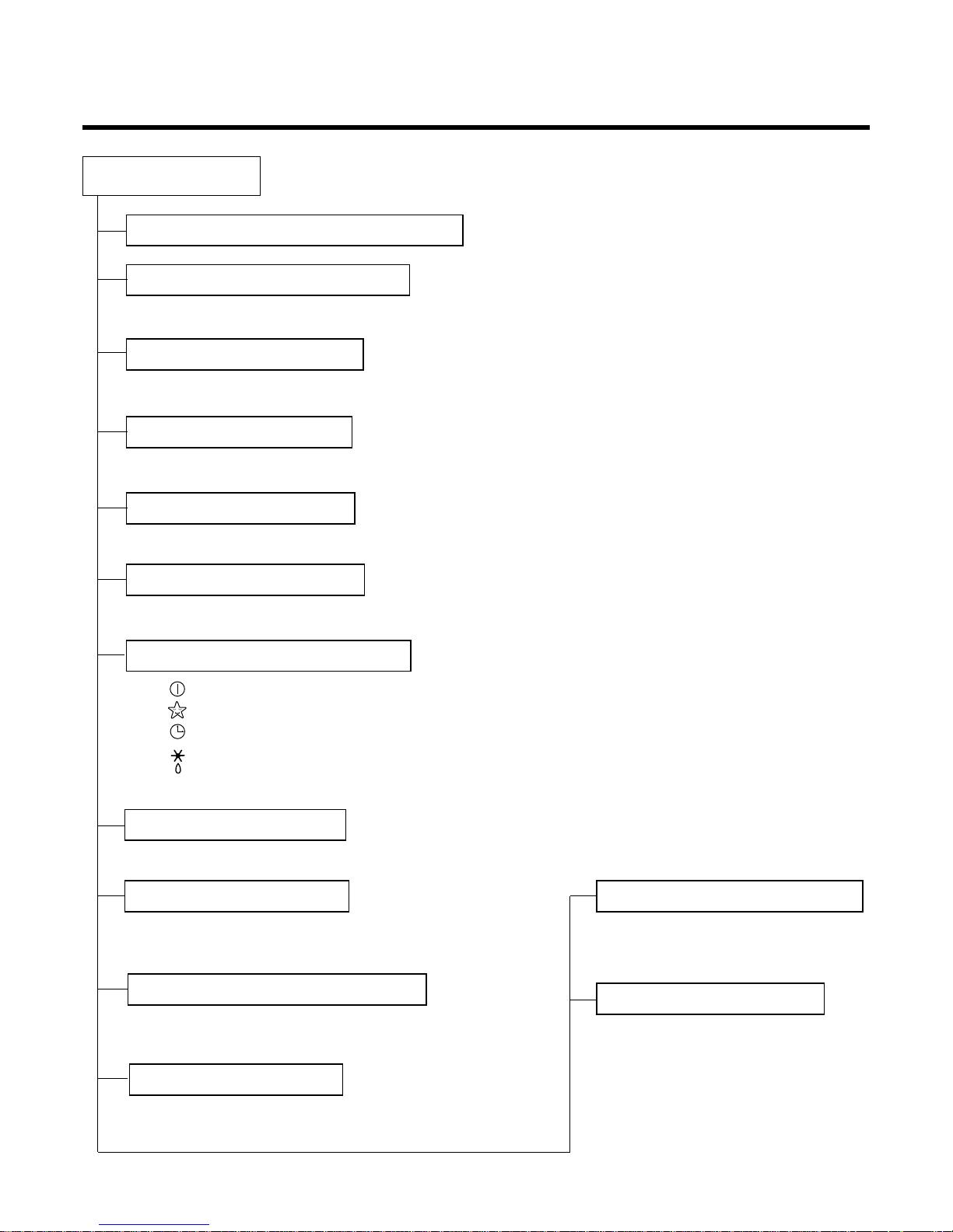
Contents
Functions
................................................................................................................................
3
Product Specifications
.........................................................................................................
5
Dimensions
.............................................................................................................................
6
Refrigeration Cycle Diagram
.................................................................................................
8
Wiring Diagram
.......................................................................................................................
9
Operation Details
.................................................................................................................
10
Display Function
..................................................................................................................
17
Self-diagnosis Function
.......................................................................................................
17
Installation
............................................................................................................................
18
Operation
..............................................................................................................................
34
Disassembly of the parts (Indoor Unit)
..............................................................................
36
2-way, 3-way Valve
................................................................................................................
42
Cycle Troubleshooting Guide
..............................................................................................
49
Electronic Parts Troubleshooting Guide
............................................................................
50
Electronic Control Device
....................................................................................................
57
Schematic Diagram
..............................................................................................................
59
Exploded View and Replacement Parts List
......................................................................
61
-2-
Functions
• Room temperature sensor. (THERMISTOR)
• Maintains the room temperature in accordance with the Setting Temp.
• Indoor fan is delayed for 5 sec at the starting.
• Restarting is inhibited for approx. 3 minutes.
• High, Med, Low, CHAOS
--- Lights up in operation
--- Lights up in Sleep Mode
--- Lights up in Timer Mode
--- Lights up in Defrost Mode (for Heating Model)
OUTDOOR --- Lights up in compressor operation (for Cooling Model)
• Intermittent operation of fan at low speed.
• The fan is switched to low(Cooling), med(Heating) speed.
• The unit will be stopped after 1, 2, 3, 4, 5, 6, 7 hours.
• The fan is switched to intermittent or irregular operation
•
The fan speed is automatically switched from high to low speed.
• The louver can be set at the desired position or swing
up and down automatically.
Indoor Unit
Operation ON/OFF by Remote controller
Sensing the Room Temperature
Room temperature control
Starting Current Control
Time Delay Safety Control
Indoor Fan Speed Control
Operation indication Lamps (LED)
Soft Dry Operation Mode
• Both the indoor and outdoor fan
stops during defrosting.
• The indoor fan stops until the
evaporator pipe temperature will be
reached at 28°C.
Sleep Mode Auto Control
Natural Air Control by CHAOS Logic
Airflow Direction Control
-3-
Defrost(Deice) control (Heating)
Hot-start Control (Heating)
-4-
Healthy Dehumidification Operation Mode.
( )
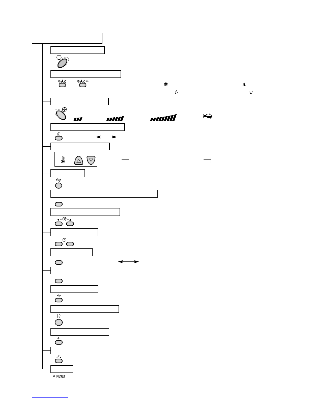
Remote Controller
Operation ON/OFF
Reset
Operation Mode Selection
Temperature Setting
Timer Selection
Timer Setting
JET COOL
Timer Cancel
Sleep Operation
Airflow Direction Control
(Cooling
model only)
(Heating
model only)
TEMPERATURE
LOW HIGH
Cooling Operation Mode.( )
Heating Operation Mode.( )
Auto Operation Mode.( )
Fan Operation Mode
Horizontal Airflow Direction Control Button(Option)
Room, Temperature Display
Setting the Time or Timer
PLASMA(Option)/NEGATIVE ION(Option)
ON OFF
SET
PLASMA
CANCEL
Fan Speed Selection
(Low) (Med) (High) (CHAOS)
: (High:39°C Low:11°C)
: OFF, ON, OFF ON
: Cancel Sleep Mode, Timer ON or Timer OFF
: 1, 2, 3, 4, 5, 6, 7, Off Timer
: Fan Operates without cooling or heating.
Cooling
Down to 18°C
Up to 30°C
Heating
Down to 16°C
Up to 30°C
-5-
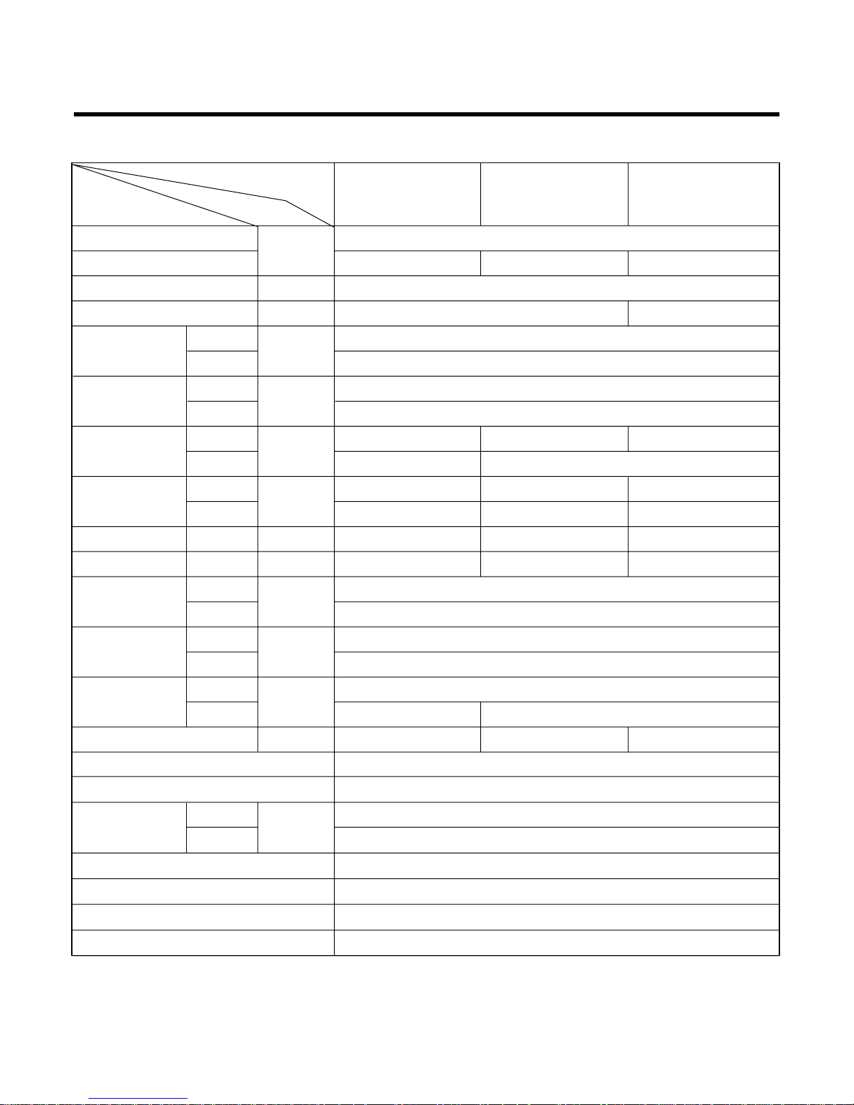
Product Specifications
Model Name
Item Unit
Cooling Capacity
Btu/h
12,000
Heating Capacity - 13,000 12,500
Moisture Removal l/h 1.5
Power Source Ø, V, Hz 1Ø, 220-240V, 50Hz 1Ø, 220V, 60Hz
9.5
25
36
46
Cooling
W
1,190 1,280 1,260
Heating - 1,150
Running Cooling
A
5.4 5.8 5.9
Current Heating - 5.2 5.5
E.E.R. Cooling Btu/hW 10.1 9.4 9.5
C.O.P Heating - 3.31 3.19
13
26
888 x 287 x 170
770 x 540 x 245
9
34 35
Refrigerant (R22) kg 0.73 0.81 0.84
Airflow Direction Control (Up & Down) O
Remocon Type L.C.D Wireless
inch(mm)
1/4" (6.35)
1/2" (12.7)
Sleeping Operation O
Drain Hose O
Connecting Cable 1.0mm
2
Power Cord 1.0mm
2
Air Circulation
Noise Level
Input
m3/min
dB (A)±3
Indoor
Outdoor
Indoor
Outdoor
Indoor
Outdoor
Indoor
Outdoor
Indoor
Outdoor
Liquid
Gas
Service Valve
Motor Output
Dimensions
(W x H x D)
Net. Weight
W
mm
kg
LS-L1261/1262CL/1263DL LS-L1261/1262HL/1261EL LS-L1220HL
-6-
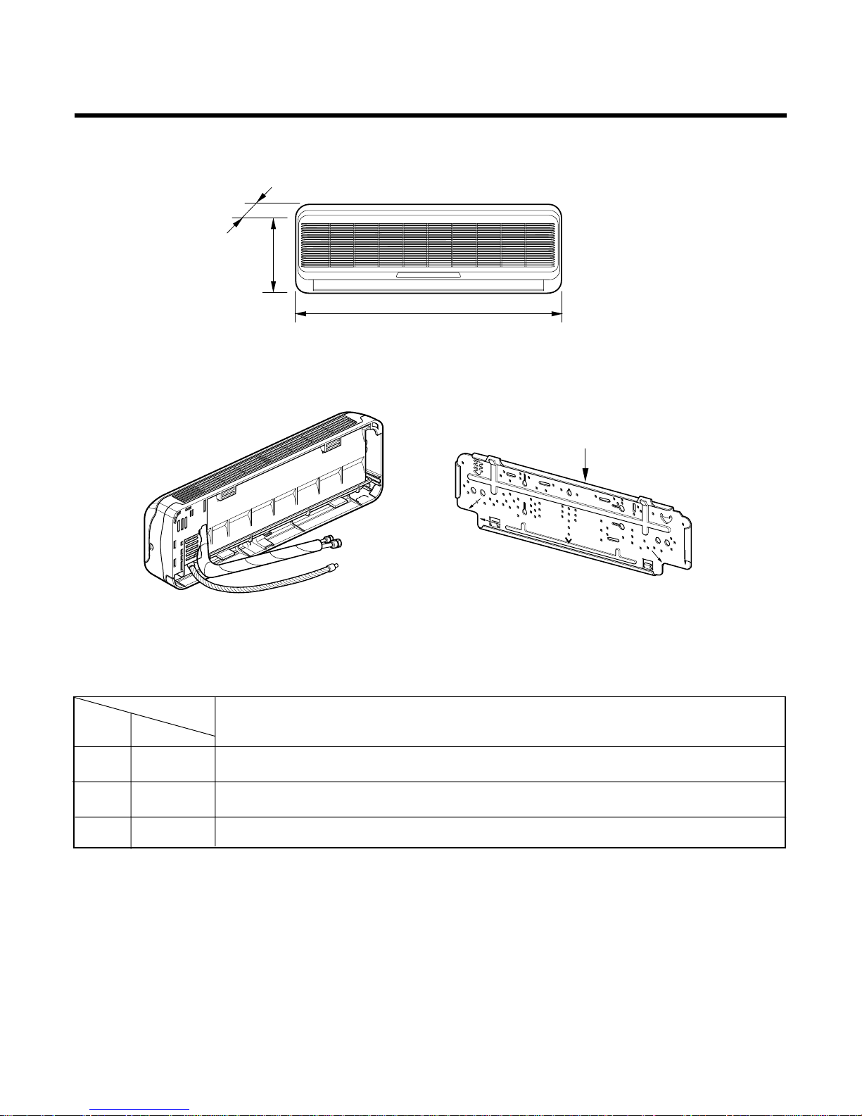
Installation plate
D
H
W
MODEL
DIM Unit
W mm 888
H mm 287
D mm 170
12K Btu Series
Dimensions
(1) Indoor Unit
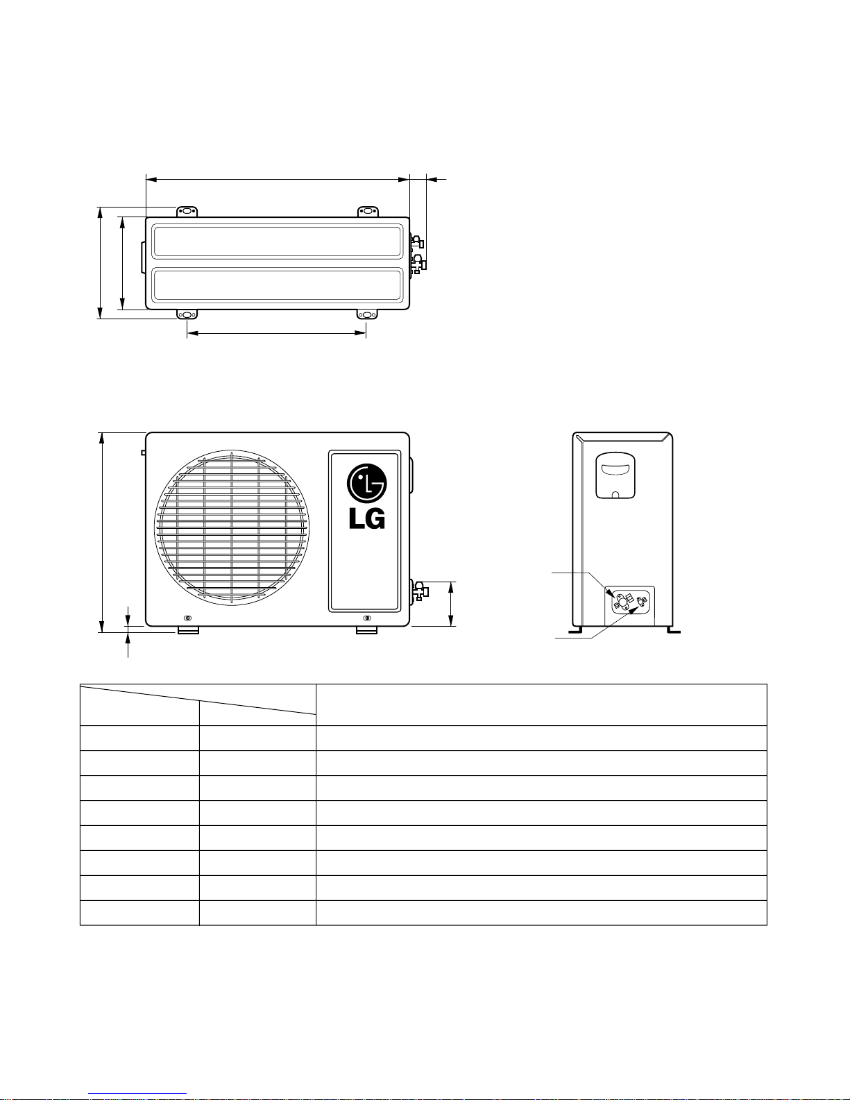
-7-
(2) Outdoor Unit
W
L2
L3
L1
D
H
L4
L5
Gas side
(3-way valve)
Liquid side
(2-way valve)
MODEL
12K Btu Series
DIM unit
W mm 770
H mm 540
D mm 245
L1 mm 287
L2 mm 64
L3 mm 518
L4 mm 10
L5 mm 100
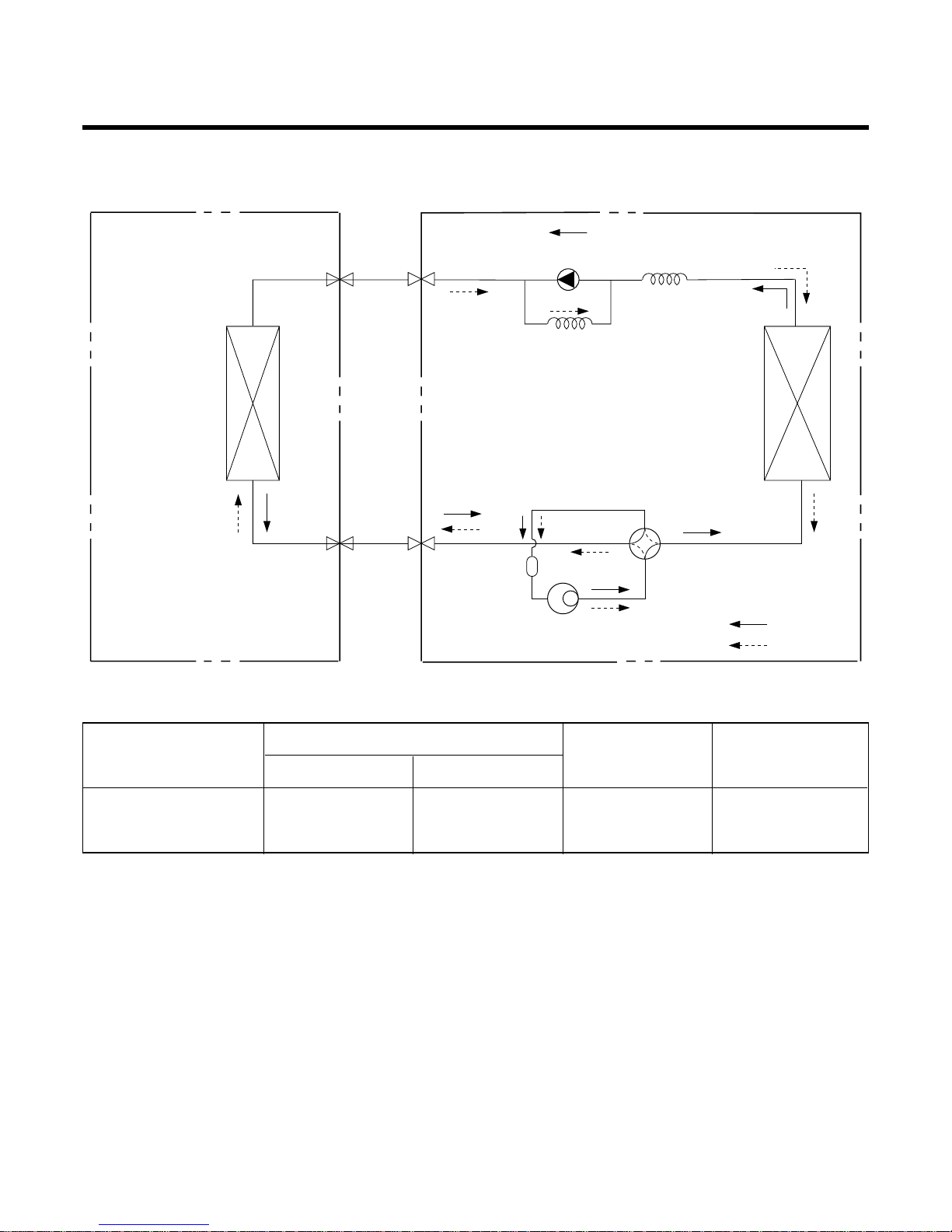
Refrigeration Cycle Diagram
-8-
Pipe size(Diameter:Ø)
MAX. Max
MODEL Piping length Elevation
Gas(inch) Liquid(inch)
(m) (m)
1/2" 1/4" 15 7
INDOOR UNIT OUTDOOR UNIT
HEAT
EXCHANGE
(EVAPORATOR)
HEAT
EXCHANGE
(CONDENSER)
COMPRESSOR
ACCUMU
LATOR
GAS SIDE
3-WAY VALVE
LIQUID SIDE
2-WAY VALVE
CAPILLARY TUBE
CHECK VALVE
(Heating Model only)
COOLING
HEATING
REVERSING
VALVE
(Heating Model Only)
12K Btu SERIES
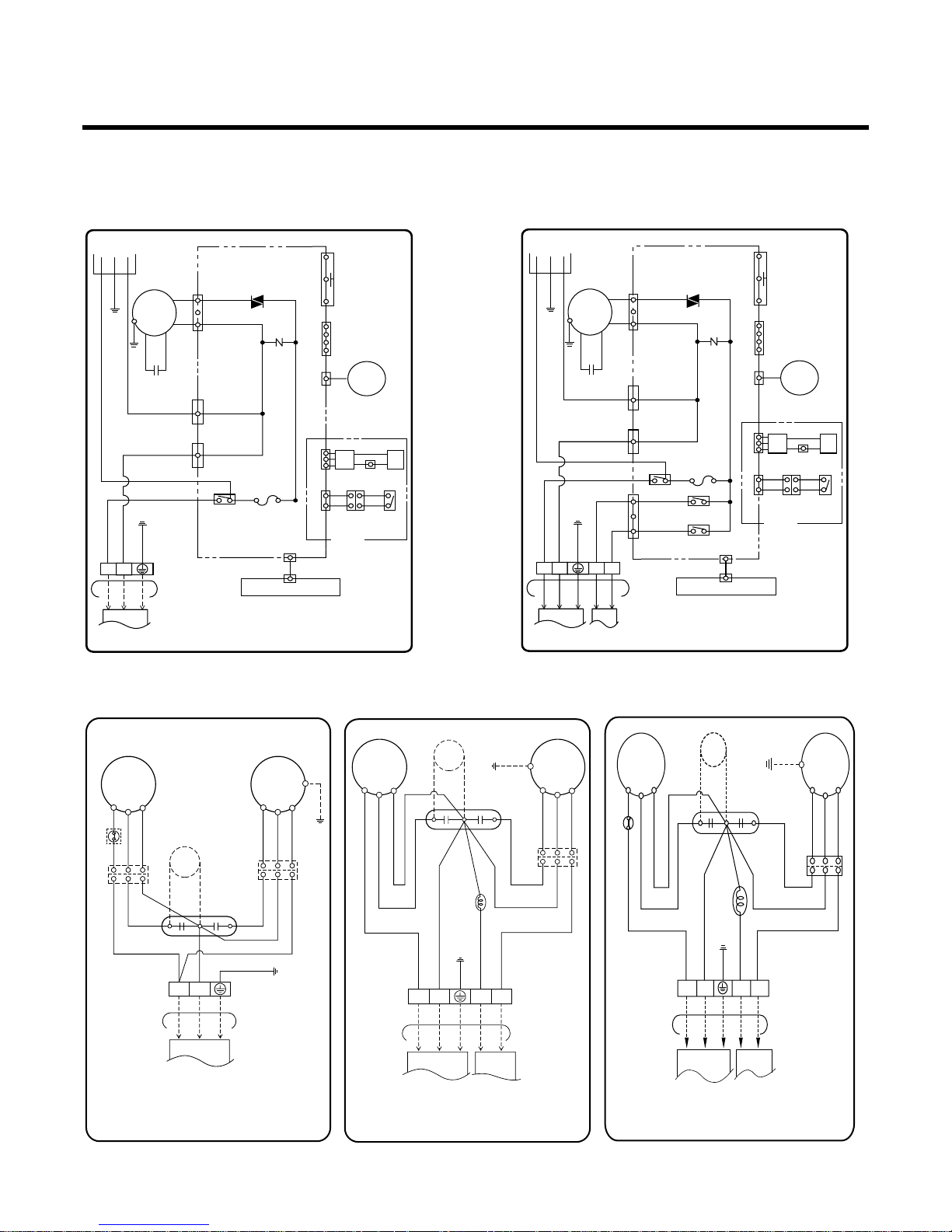
Wiring Diagram
-9-
BL
BK
(RD)
BK
(RD)
BL
YL
YL
BR
RD
RD BL YL
GN/YL
BL BK
RD
BR
GN/YL
BL BL
GN/YL
PTC
3854A30077D
FAN
MOTOR
RD
BL
BR
C
S
R
COMP.
REVERSING
VALVE
OUTDOOR WIRING DIAGRAM
TERMINAL
BLOCK
TO INDOOR UNIT
OLP
H
CF
CAPACITOR
1(L) 2(N) 3 4
3854A30077A
INDOOR WIRING DIAGRAM
CN-DISP1
FUSE
AC250V/T2A
CN-TH1
TRIAC
SH-CAPA.
BL/RIBBED
BR/PLAIN
GN/YL
BR
YL
OR
BK
CN-TAB1
CN-MOTOR
CN-TAB2
RY-COMP.
ZNR
THERMISTOR
FORCED
OPERATION
AUTO
RESTART
REMOTE
CONTROL
MOTOR
MAIN PCB
ASM
DISPLAY PCB ASM
POWER
TO OUTDOOR UNIT
PILLAR
TERMINAL
BRBLGN/YL
BR
BL
GN/YL
1(L) 2(N
)
3
4
BL
CN-U/D
STEP
MOTOR
H.V.B A/CL
OPTION
RD
BKBK
BK BK
BK BK
LIMIT
S/W
3854AR6093Y
INDOOR WIRING DIAGRAM
CN-DISP1
FUSE
AC250V/T2A
CN-TH1
TRIAC
SH-CAPA.
BL
BR
GN/YL
BR
YL
OR
BK
CN-TAB1
CN-MOTOR
CN-TAB2
CN-4WAY
RY-COMP.
RY-4WAY
RY-FAN
ZNR
THERMISTOR
FORCED
OPERATION
AUTO
RESTART
REMOTE
CONTROL
MOTOR
MAIN PCB
ASM
DISPLAY PCB ASM
POWER
TO OUTDOOR UNIT
PILLAR
TERMINAL
BR
BL
BK
RD
GN/YL
BR
BL
BK
RD
GN/YL
1(L) 2(N
)
34
3
4
BL
BR
CN-U/D
STEP
MOTOR
OPTION
BK BK
BK BK
LIMIT
S/W
H.V.B A/CL
RD
BKBK
COMP
C
S
R
FAN
MOTOR
OLP
BRBRRD BL
BR RD
BL
BL
GN/YL
BR BL
GN/YL
BL BL
RD BL YL
GN/YL
CAPACITOR
BR
RD
BL
YL
TO INDOOR UNIT
OUTDOOR WIRING DIAGRAM
3854A30077B
TERMINAL
BLOCK
HCF
PTC
1(L)2(N
)
COMP
C
S
R
FAN
MOTOR
BR RD BL
BR BL
BK(RD)
YL
GN/YL
BR BL BK RD
GN/YL
BL BL
REVERSING
VALVE
RD BL YL
GN/YL
BK(RD)
CAPACITOR
RD
BL
YL
TO INDOOR UNIT
OUTDOOR WIRING DIAGRAM
3854A30077T
TERMINAL
BLOCK
HCF
PTC
1(L)2(N
)
34
1. LS-L1261/1262CL/1263DL 2. LS-L1261/1262/1220HL/1261EL
1. LS-L1261/1262CL/1263DL 2. LS-L1261/1262HL/1261EL 3. LS-L1220HL
(1) Indoor Unit
(2) Outdoor Unit

Operation Details
1. MAIN UNIT FUNCTION
• DISPLAY
1) C/O Model
Operation Indicator
• On while in appliance operation, off while in appliance pause
• Flashing while in disconnection or short in Thermistor (3 sec off / 0.5 sec on)
Sleep Timer Indicator
• On while in sleep timer mode, off when sleep timer cancel or appliance operation pause
Timer Indicator
• On while in timer mode (on/off), off when timer mode is completed or canceled.
Comp. Running Incidator
• While in appliance operation, on while in outdoor unit compressor running, off while in compressor off
2) H/P Model
Operation Indicator
• On while in appliance operation, off while in appliance pause
• Flashing while in disconnection or short in Thermistor (3 sec off / 0.5 sec on)
Sleep Timer Indicator
• On while in sleep timer mode, off when sleep timer cancel or appliance operation pause
Timer Indicator
• On while in timer mode (on/off), off when timer mode is completed or canceled
Defrost Indicator
• Off except when hot start during heating mode operation or while in defrost control
■ Cooling Mode Operation
• When the intake air temperature reaches 0.5°C below the setting temp, the compressor and the outdoor fan
stop.
• When it reaches 0.5°C above the setting temp, they start to operate again.
Compressor ON Temp ➲ Setting Temp+0.5°C
Compressor OFF Temp ➲ Setting Temp-0.5°C
• While in compressor running, operating with the airflow speed set by the remote control. While in compressor
not running, operating with the low airflow speed regardless of the setting.
■ Healthy Dehumidification Mode
• When the dehumidification operation input by the remote control is received, the intake air temperature is
detected and the setting temp is automatically set according to the intake air temperature.
26°C ≤ Intake Air Temp ➲ 25°C
24°C ≤ Intake Intake Air Temp<26°C ➲ Intake Air Temp-1°C
18°C ≤ Intake Intake Air Temp<24°C ➲ Intake Air Temp-0.5°C
Intake Air Temp<18°C ➲ 18°C
-10-

• While in compressor off, the indoor fan repeats low airflow speed and pause.
• While the intake air temp is between compressor on temp. and compressor off temp., 10-min dehumidifica-
tion operation and 4-min compressor off repeat.
Compressor ON Temp. ➲ Setting Temp+0.5°C
Compressor OFF Temp. ➲ Setting Temp-0.5°C
• In 10-min dehumidification operation, the indoor fan operates with the low airflow speed.
■ Heating Mode Operation
• When the intake air temp reaches +3°…above the setting temp, the compressor is turned off. When below
the setting temp, the compressor is turned on.
Compressor ON Temp. ➲ Setting Temp.
Compressor OFF Temp. ➲ Setting Temp.+3°C
• While in compressor on, the indoor fan is off when the indoor pipe temp. is below 20°C, when above 28°C , it
operates with the low or setting airflow speed. When the indoor pipe temp is between 20°C and 28°C, it operates with Super-Low(while in sleep mode, with the medium airflow speed).
• While in compressor off, the indoor fan is off when the indoor pipe temp is below 33°C, when above 35°C , it
operates with the low airflow speed.
• If overloaded while in heating mode operation, in order to prevent the compressor from OLP operation, the
outdoor fan is turned on/off according to the indoor pipe temp.
• While in defrost control, both of the indoor and outdoor fans are turned off.
■ Defrost Control
• While in heating mode operation in order to protect the evaporator pipe of the outdoor unit from freezing,
reversed to cooling cycle to defrost the evaporator pipe of the outdoor unit.
• After 40 min heating mode operation, at 4 min interval, whether to carry out defrost control or not and the time
of defrost control are determined according to the following conditions.
1) While in heating mode operation, the maximum of the indoor pipe temperature is measured and it is com-
pared with the present indoor pipe temperature to get the difference of the indoor pipe temperatures (=the
maximum temperature of indoor pipe ? the present temperature of indoor pipe), according to which, whether
to carry out defrost control or not is determined.
2) According to the need of defrost control shown above and the elapsed time of heating mode operation at that
moment, the defrost control time is determined.
3) When the determined time of defrost control is below 7 min, heating mode operation continues without carry-
ing out defrost control. According to the procedure stated above, the determination is made again. When the
defrost control time is 7 min or longer, defrost control is then carried out.
• While in defrost control, the minimum temp of the indoor pipe is measured and it is compared with the present
temp of the indoor pipe to get the difference of the indoor pipe temperatures (=the present temperature of the
indoor pipe ? the minimum temperature of the indoor pipe). When the difference is 5°C or higher, defrost control is completed and heating mode operation is carried out.
• While in defrost control, if the defrost time determined before the start of defrost control is completed, defrost
control stops and heating mode operation is carried out regardless of the above condition.
• When the indoor pipe temp is 42°C or above, defrost control is not carried out even if the condition is one of
the defrost conditions above.
• While in defrost control, the compressor is on and the indoor fan, the outdoor fan, and the 4 way valve are off.
-11-

-12-
■ Fuzzy Operation (C/O Model)
• According to the temperature set by Fuzzy rule, when the intake air temp is 0.5°C or more below the setting
temp, the compressor is turned off. When 0.5°C or more above the setting temp, the compressor is turned on.
Compressor ON Temp ➲ Setting Temp + 0.5°C
Compressor OFF Temp ➲ Setting Temp + 0.5°C
• At the beginning of Fuzzy mode operation, the setting temperature is automatically selected according to the
intake air temp at that time.
26°C ≤ Intake Air Temp ➲ 25°C
24°C ≤ Intake Air Temp < 26°C ➲ Intake Air Temp + 1°C
22°C ≤ Intake Air Temp < 24°C ➲ Intake Air Temp + 0.5°C
18°C ≤ Intake Air Temp < 22°C ➲ Intake Air Temp
Intake Air Temp<18°C ➲ 18°C
• When the Fuzzy key (Temperature Control key) is input after the initial setting temperature is selected, the
Fuzzy key value and the intake air temperature at that time are compared to select the setting temperature
automatically according to the Fuzzy rule.
• While in Fuzzy operation, the airflow speed of the indoor fan is automatically selected according to the
temperature.
■ Fuzzy Operation (H/P Model)
• When any of operation mode is not selected like the moment of the power on or when 3 hrs has passed since
the operation off, the operation mode is selected.
• When determining the operation mode, the compressor, the outdoor fan, and the 4 way valve are off and only
the indoor fan is operated for 15 seconds. Then an operation mode is selected according to the intake air
temp at that moment as follows.
24°C ≤ Inatake Air Temp ➲ Fuzzy Operation for Cooling
21°C ≤ Inatake Air Temp<24°C ➲ Fuzzy Operation for Dehumidification
Inatake Air Temp<21°C ➲ Fuzzy Operation for Heating
• If any of the operation modes among cooling / dehumidification / heating mode operations is carried out for 10
sec or longer before Fuzzy operation, the mode before Fuzzy operation is operated.
1) Fuzzy Operation for Cooling
• According to the setting temperature selected by Fuzzy rule, when the intake air temp is 0.5°C or more below
the setting temp, the compressor is turned off. When 0.5°C or more above the setting temp, the compressor
is turned on.
Compressor ON Temp ➲ Setting Temp +0.5°C
Compressor OFF Temp ➲ Setting Temp + 0.5°C
• At the beginning of Fuzzy mode operation, the setting temperature is automatically selected according to the
intake air temp at that time.
26°C≤ Intake Air Temp ➲ 25°C
24°C≤ Intake Air Temp<26°C ➲ Intake Air Temp + 1°C
22°C≤ Intake Air Temp<24°C ➲ Intake Air Temp + 0.5°C
18°C≤ Intake Air Temp<22°C ➲ Intake Air Temp
Intake Air Temp<18°C ➲ 18°C
• When the Fuzzy key (Temperature Control key) is input after the initial setting temperature is selected, the
Fuzzy key value and the intake air temperature at that time are compared to select the setting temperature
automatically according to the Fuzzy rule.
• While in Fuzzy operation, the airflow speed of the indoor fan is automatically selected according to the temperature.

-13-
2) Fuzzy Operation for Dehumidification
• According to the setting temperature selected by Fuzzy rule, when the intake air temp is 0.5°C or more below
the setting temp, the compressor is turned off. When 0.5°C or more above the setting temp, the compressor
is turned on.
Compressor ON Temp ➲ Setting Temp + 0.5°C
Compressor OFF Temp ➲ Setting Temp+0.5°C
• At the beginning of Fuzzy mode operation, the setting temperature is automatically selected according to the
intake air temp at that time.
26°C ≤ Intake Air Temp ➲ 25°C
24°C ≤ Intake Air Temp<26°C ➲ Intake Air Temp+1°C
22°C ≤ Intake Air Temp<24°C ➲ Intake Air Temp+0.5°C
18°C ≤ Intake Air Temp<22°C ➲ Intake Air Temp
Intake Air Temp<18°C ➲ 18°C
• When the Fuzzy key (Temperature Control key) is input after the initial setting temperature is selected, the
Fuzzy key value and the intake air temperature at that time are compared to select the setting temperature
automatically according to the Fuzzy rule.
• While in Fuzzy operation, the airflow speed of the indoor fan repeats the low airflow speed or pause as in
dehumidification operation.
3) Fuzzy Operation for Heating
• According to the setting temperature selected by Fuzzy rule, when the intake air temp is 3°C or more above
the setting temp, the compressor is turned off. When below the setting temp, the compressor is turned on.
Compressor ON Temp ➲ Setting Temp
Compressor OFF Temp ➲ Setting Temp + 3°C
• At the beginning of Fuzzy mode operation, the setting temperature is automatically selected according to the
intake air temp at that time.
20°C≤Intake Air Temp ➲ Intake Air Temp + 0.5°C
Intake Air Temp<20°C ➲ 20°C
• When the Fuzzy key (Temperature Control key) is input after the initial setting temperature is selected, the
Fuzzy key value and the intake air temperature at that time are compared to select the setting temperature
automatically according to the Fuzzy rule.
• While in Fuzzy operation, the airflow speed of the indoor fan is set to the high or the medium according to the
intake air temperature and the setting temperature.
■ Airflow Speed Selection
• The airflow speed of the indoor fan is set to high, medium, low, or chaos (auto) by the input of the airflow
speed selection key on the remote control.
■ On-Timer Operation
• When the set time is reached after the time is input by the remote control, the appliance starts to operate.
• The timer LED is on when the on-timer is input. It is off when the time set by the timer is reached.
• If the appliance is operating at the time set by the timer, the operation continues.
-14-
■ Off-Timer Operation
• When the set time is reached after the time is input by the remote control, the appliance stops operating.
• The timer LED is on when the off-timer is input. It is off when the time set by the timer is reached.
• If the appliance is on pause at the time set by the timer, the pause continues.
■ Off-Timer <=> On-Timer Operation
• When the set time is reached after the on/off time is input by the remote control, the on/off-timer operation is
carried out according to the set time.
■ Sleep Timer Operation
• When the sleep time is reached after <1,2,3,4,5,6,7,0(cancel) hr> is input by the remote control while in appliance operation, the operation of the appliance stops.
• While the appliance is on pause, the sleep timer mode cannot be input.
• While in cooling mode operation, 30 min later since the start of the sleep timer, the setting temperature
increases by 1°C. After another 30 min elapse, it increases by 1°C again.
• When the sleep timer mode is input while in cooling cycle mode, the airflow speed of the indoor fan is set to the
low.
• When the sleep timer mode is input while in heating cycle mode, the airflow speed of the indoor fan is set to
the medium.
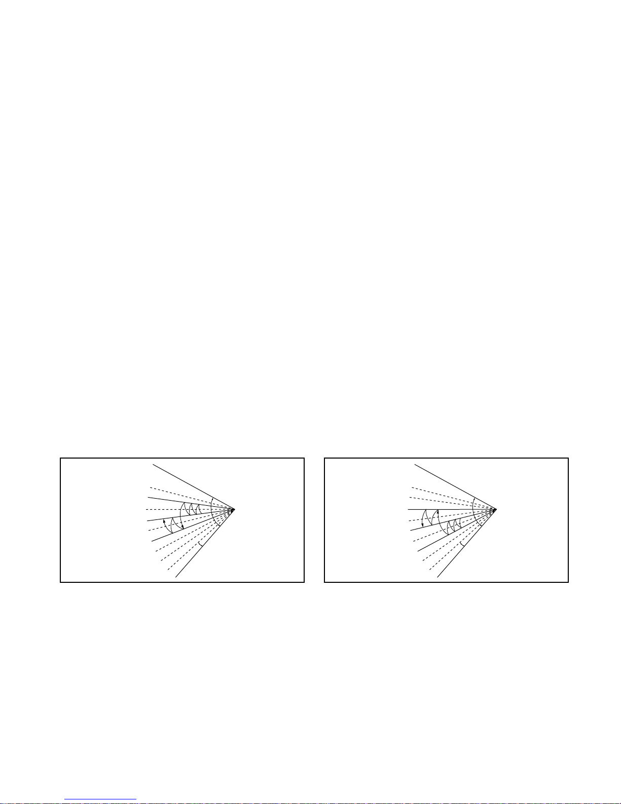
■ Chaos Swing Mode
• By the Chaos Swing key input, the upper/lower vane automatically operates with the Chaos Swing or they are
fixed to the desired direction.
• While in Chaos Swing mode, the angles of cooling and heating cycle operations are different.
■ Chaos Natural Wind Mode
• When the Chaos Natural Wind mode is selected and then operated, the high, medium, or low speed of the airflow mode is operated for 2~15 sec. randomly by the Chaos Simulation.
CLOSED
OPEN
< Cooling Mode >
7°
CLOSED
OPEN
< Heating Mode >
7°
-15-
■ Jet Cool Mode Operation (C/O Model)
• If the Jet Cool key is input at any operation mode while in appliance operation, the Jet Cool mode operates.
• In the Jet Cool mode, the indoor fan is operated at super-high speed for 30 min at cooling mode operation.
• In the Jet Cool mode operation, the room temperature is controlled to the setting temperature, 18°C
• When the sleep timer mode is input while in the Jet Cool mode operation, the Jet Cool mode has the priority.
• When the Jet Cool key is input, the upper/lower vanes are reset to those of the initial cooling mode and then
operated in order that the air outflow could reach further.
■ Jet Cool Mode Operation (H/P Model)
• While in heating mode or Fuzzy operation, the Jet Cool key cannot be input. When it is input while in the other
mode operation (cooling, dehumidification, ventilation), the Jet Cool mode is operated.
• In the Jet Cool mode, the indoor fan is operated at super-high speed for 30 min at cooling mode operation.
• In the Jet Cool mode operation, the room temperature is controlled to the setting temperature, 18°C.
• When the sleep timer mode is input while in the Jet Cool mode operation, the Jet Cool mode has the priority.
• When the Jet Cool key is input, the upper/lower vanes are reset to those of the initial cooling mode and then
operated in order that the air outflow could reach further.
■ Auto Restarting Operation
• When the power is restored after a sudden power failure while in appliance operation, the mode before the
power failure is kept on the memory and the appliance automatically operates in the mode on the memory.
• The slide switch on the main unit of the appliance should be on the Auto Restarting position in order that the
Auto Restarting operation is available.
• Operation Mode that is kept on the memory
- State of Operation ON/OFF
- Operation Mode/Setting Temp/Selected Airflow Speed
- Sleep Timer Mode/Remaining Time of Sleep Timer (unit of hour)
Slide Switch
FORCED
OPERATION
AUTO
RESTART
REMOTE
CONTROL
■ Forced Operation (C/O Model)
• To operate the appliance by force in case that the remote control is lost, the forced operation selection switch is
on the main unit of the appliance to operate the appliance in the standard conditions.
• When the power is supplied while the slide switch is on the forced operation position, or when the slide switch
position is switched to the Auto Restarting position (or test operation) or switched from the remote control position to the forced operation position while the power is on, the forced operation is carried out.
• When the slide switch position is switched from the forced operation position to the Auto Restarting position or
the remote control position, the forced operation is canceled and the appliance stops operating.
• The forced operation is carried out in cooling mode with the setting temperature 22°C and the high speed of
airflow.
• While in forced operation, the key input by the remote control has no effect and the buzzer sounds 10 times to
indicate the forced operation.

-16-
■ Forced Operation (H/P Model)
• To operate the appliance by force in case that the remote control is lost, the forced operation selection switch
is on the main unit of the appliance to operate the appliance in the standard conditions.
• When the power is supplied while the slide switch is on the forced operation position, or when the slide switch
position is switched to the Auto Restarting (or test operation) position or switched from the remote control
position to the forced operation position while the power is on, the forced operation is carried out.
• When the slide switch position is switched from the forced operation position to the Auto Restarting position or
the remote control position, the forced operation is canceled and the appliance stops operating.
• The forced operation is carried out in cooling mode with the setting temperature 22°C and the high speed of
airflow.
• In the forced operation mode, the indoor fan is operated at low speed for around 15 sec and then the operation condition is set according to the intake air temperature as follows.
24°C≤Intake Air Temp ➲ Cooling Mode Operation, 22°C, High Speed
21°C≤Intake Air Temp<24°C ➲ Dehumidification Operation, 23°C, High Speed
Intake Air Temp<21°C ➲ Heating Mode Operation, 24°C, High Speed
• While in forced operation, the key input by the remote control has no effect and the buzzer sounds 10 times to
indicate the forced operation.
■ Remote Control Operation Mode
• When the remote control is selected by the slide switch on the main unit, the appliance operates according to
the input by the remote control.
■ Protection of the evaporator pipe from frosting
• If the indoor pipe temp is below 0°C in 7 min. after the compressor operates without any pause while in cooling cycle operation mode, the compressor and the outdoor fan are turned off in order to protect the indoor
evaporator pipe from frosting.
• When the indoor pipe temp is 7°C or higher after 3 min. pause of the compressor, the compressor and the
outdoor fan is turned on according to the condition of the room temperature.
■ Buzzer Sounding Operation
• When the appliance-operation key is input by the remote control, the short "beep-beep-" sounds.
• When the appliance-pause key is input by the remote control, the long "beep—" sounds.
• When a key is input by the remote control while the slide switch on the main unit of the appliance is on the
forced operation position, the error sound "beep-beep-beep-beep-beep-" is made 10 times to indicate that the
remote control signal cannot be received.
■ Air Cleaner Operation
• When an air cleaner function is selected during Air Conditioner operation
- Plasma air cleaner function will be operated while in any operation mode with selecting the function.
- The function is to be stopped while it is operating with selecting the function.
• When an air cleaner function is selected during operation off
- The function will be only operated.
• When inlet grille of air conditioner is opened during plasma operation, High Voltage Generator(H.V.B) is to be
stopped. When inlet grille of air conditioner is closed during plasma operation, High Voltage Generator(H.V.B)
will be operated again.
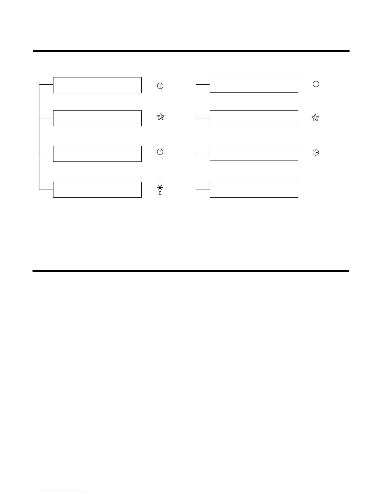
Display Function
1. Heating Model 2. Cooling Model
• Cooling, Soft Dry, Fan, Heating • Cooling, Soft Dry, Fan
• Sleep Mode • Sleep Mode
• Timer Mode • Timer Mode
• Hot-start, Defrost
Self-diagnosis Function
■ Thermistor Error Indicator
• When the indoor pipe sensor or the room temperature sensor is open or is shorted, the error is indicated.
• To indicate the error, the operation LED (or the cooling LED) flashed at 3 sec interval.
• When the error is cleared, the LED stops flashing, the operation (or cooling) LED is on.
• While in appliance pause, the error is not indicated.
Operation Indicator
Timer Indicator
Sleep Timer Indicator
Defrost Indicator
-17-
Operation Indicator
Timer Indicator
Sleep Timer Indicator
Compressor on Indicator
OUT
DOOR
Installation
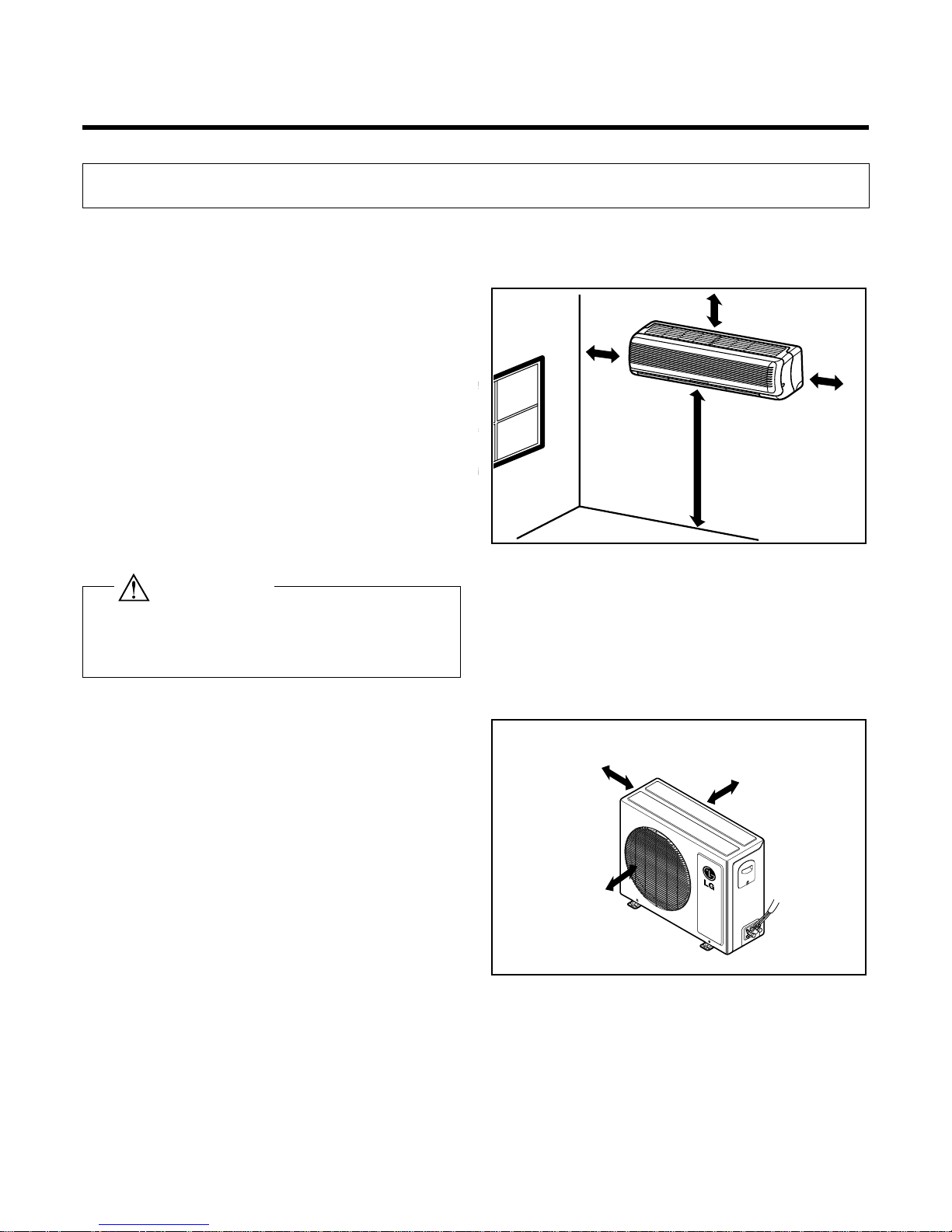
1. Installation of indoor, Outdoor unit
-18-
More than 2.3 m
More than 5 cm
More than
5 cm
More than
5 cm
More than 10 cm
More than 10 cm
More than 70 cm
1) Selection of the best location
1. Indoor unit
2. Outdoor unit
• There should not be any heat source or steam
near the unit.
• There should not be any obstacles to prevent the
air circulation.
• A place where air circulation in the room will be
good.
• A place where drainage can be easily obtained.
• A place where noise prevention is taken into consideration.
• Do not install the unit near the door way.
• Ensure the spaces indicated by arrows from the
wall, ceiling, fence or other obstacles.
• If an awning is built over the unit to prevent
direct sunlight or rain exposure, be careful
that heat radiation from the condenser is not
restricted.
• There should not be any animals or plants
which could be affected by hot air discharged.
• Ensure the correct distance is left from the
wall, ceiling, fence, or other obstacles as indicated in the diagram.
Install the indoor unit on the wall where the height
from the floor is more than 2.3 meters.
CAUTION

-19-
5-7mm
Indoor Outdoor
WALL
ø70mm
A
A
A
A
Center
Right rear pipingLeft rear piping
Center
ø70mm
Installation plate
Marking-off line
Thread
Weight
Type "A" screw
2) Indoor Unit Installation
The mounting wall should be strong and solid enough
to protect it from the vibration.
1.Mount the installation plate on the wall with four
Type "A" screws.
(if mounting the unit on the concrete wall, consider
using anchor bolts.)
• Always mount the Installation plate horizontally by
aligning the marking-off line by means of the
thread and a level.
2. Drill the piping hole with 70mm dia. holecore
drill.
• Line according to the arrows marked on lower the
left and the right side of the Installation Plate.
The meeting point of the extended line is the center of the hole.
• Drill the Piping hole at either the r ight or the left
and the hole should be slightly slanted to the outdoor side.
The lower left and right side of Installation
Plate
12K Btu
-20-
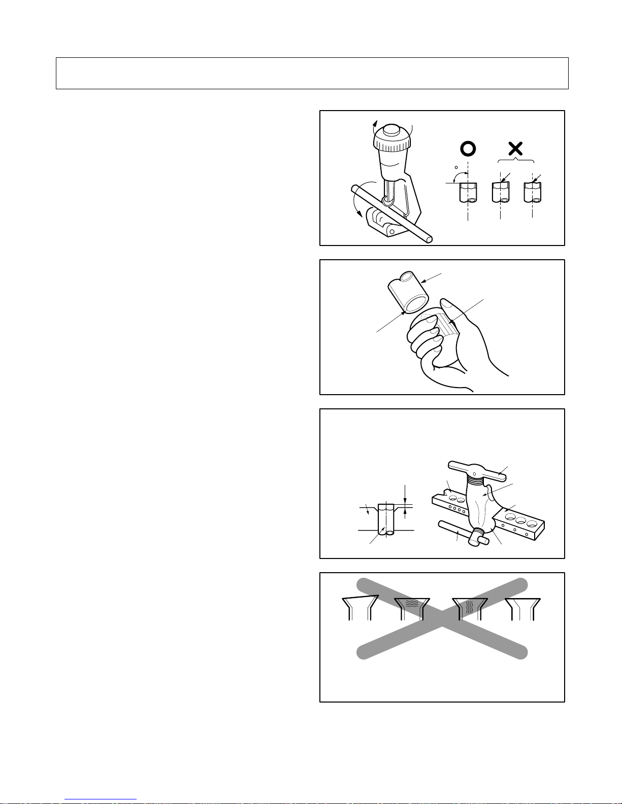
2. Piping and Drainage of Indoor Unit
1) Preparation of Piping
1. Cut the pipes and the cable.
• Use the accessory piping kit or the pipes purchased locally.
• Measure the distance between the indoor and the
outdoor unit.
• Cut the pipes a little longer than measured distance.
• Cut the cable 1.5m longer than the length of the
pipe.
2. Remove burrs.
• Remove burrs from cut edges of pipes.
• Turn the pipe end toward down to avoid the metal
powder entering the pipe.
Caution:
If burrs are not removed, they may cause a gas leakage.
3. Flaring the pipes.
• Inser t the flare nuts, mounted on the connection
ports of both indoor and outdoor unit, onto the
copper pipes. (When the flare nuts are removed
from the indoor unit.) Some gas may leak, as
some gas is charged to prevent the inside of the
pipe from rusting.
• Fit the copper pipe end into the Bar of flare tool
about 0~1.0mm higher.
(See illustration)
• Flare the pipe ends.
4. Tape the flaring portion to protect it from the
dust or damages.
90
Slanted Rough
Pipe cutter
Pipe
Reamer
Point down
"A"
Bar
Bar
Clamp handle
Red arrow mark
Cone
Yoke
Handle
Copper pipe
Inclined Cracked Uneven
thickness
Surface
damaged
= Improper flaring =
When properly flared, the internal surface of the flare will
evenly shine and be of even thickness.
After the flare part comes into contact with the connectors, carefully check the flare finish.
"A"; ø15.88 mm (5/8") →
0~1.0 mm
ø12.7 mm (1/2") →0~0.5 mm
ø9.52 mm (3/8") →0~0.5 mm
ø6.35 mm (1/4") →0~0.5 mm
-21-
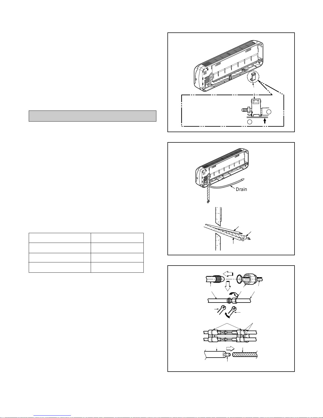
To remove the holder,
press the bottom of
chassis near the holder
upward and pull the tab
out of its hole.
Tubing holder
Pull
Press
2
1
Drain hose
Indoor Outdoor
Connecting cable
Connecting
piping
Drain pipe
Indoor unit tubing Flare nut
Spanner
Torque wrench
Plastic bands
Drain hose
Adhesive
Drain pipe
Insulation material
Pipings
2)
Connection of Pipings
1. Remove the tubing holder.
2. Route the drain hose and the indoor tubing.
For right rear piping
3. Insert the piping, the connecting cables and the
drain pipe through the piping hole on the wall.
4. Connect the piping and the indoor tubing, and
drain hose and drain pipe.
• Don't connect the cable to the indoor unit.
• Wrap the insulation material around the connect-
ing portion.
• Glue up the connection portion of drain hose and
drain pipe.
Pipe Size Torque
Liquid Side (1/4") 1.8kg.m
Gas Side (3/8") 4.2kg.m
Gas Side (1/2") 5.5kg.m
 Loading...