

Page 1

SERVICE MANUAL
Room Air Conditioner
MODEL : LS-L1260CL/CM/CN/CD/CS
LS-L1260HL/HM/HN/HD/HS
Page 2

Contents
Functions
.................................................................................................................................
3
Product Specification
............................................................................................................
5
Dimensions
..............................................................................................................................
6
Refrigeration Cycle Diagram
..................................................................................................
8
Wiring Diagram
........................................................................................................................
9
Operation Details
..................................................................................................................
10
Display Function
...................................................................................................................
17
Self-diagnosis Function
........................................................................................................
17
Installation
.............................................................................................................................
18
Operation
...............................................................................................................................
34
Disassembly of the parts (Indoor Unit)
...............................................................................
36
2-way, 3-way Valve
.................................................................................................................
39
Cycle Troubleshooting Guide
...............................................................................................
46
Electronic Parts Troubleshooting Guide
.............................................................................
47
Electronic Control Device
.....................................................................................................
54
Schematic Diagram
...............................................................................................................
56
Exploded View & Replacement Parts List
...........................................................................
58
-2-
Page 3
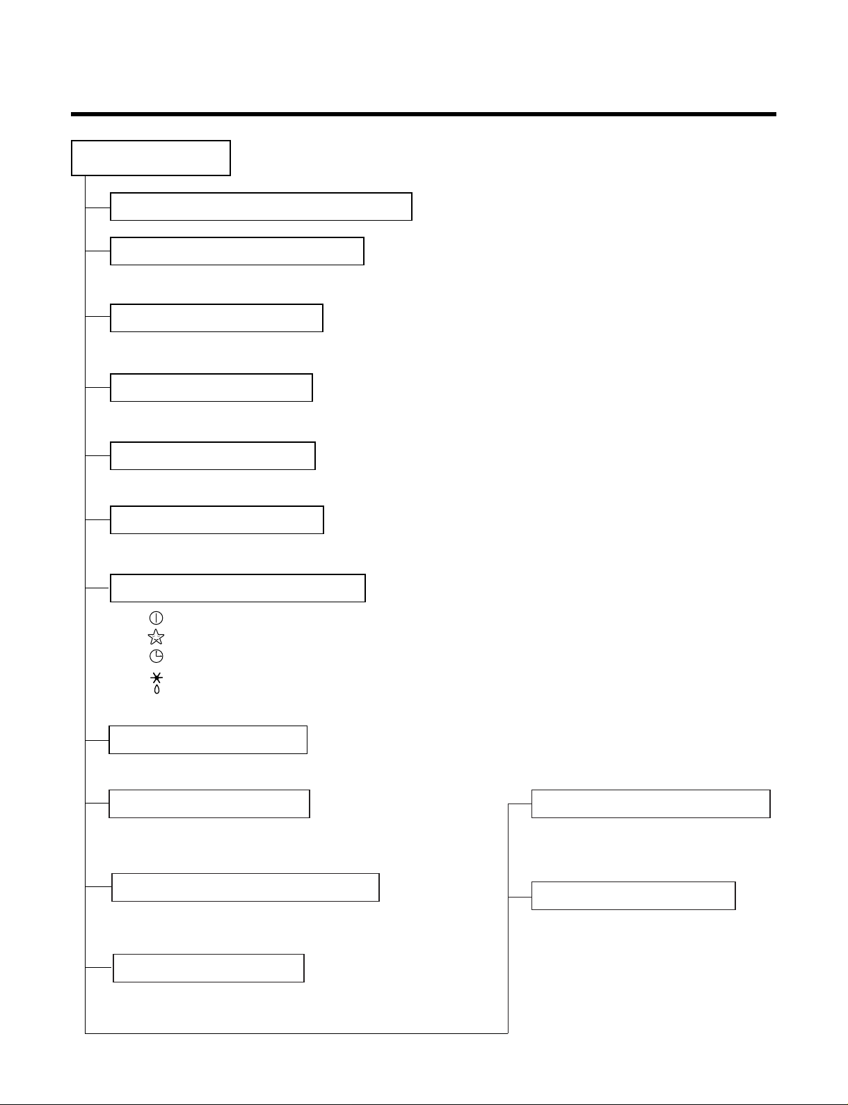
Functions
• Room temperature sensor. (THERMISTOR)
• Maintains the room temperature in accordance with the Setting Temp.
• Indoor fan is delayed for 5 sec at the starting.
• Restarting is inhibited for approx. 3 minutes.
• High, Med, Low, CHAOS
--- Lights up in operation
--- Lights up in Sleep Mode
--- Lights up in Timer Mode
--- Lights up in Defrost Mode (for Heating Model)
OUTDOOR --- Lights up in compressor operation (for Cooling Model)
• Intermittent operation of fan at low speed.
• The fan is switched to low(Cooling), med(Heating) speed.
• The unit will be stopped after 1, 2, 3, 4, 5, 6, 7 hours.
• The fan is switched to intermittent or irregular operation
•
The fan speed is automatically switched from high to low speed.
• The louver can be set at the desired position or swing
up and down automatically.
Indoor Unit
Operation ON/OFF by Remote controller
Sensing the Room Temperature
Room temperature control
Starting Current Control
Time Delay Safety Control
Indoor Fan Speed Control
Operation indication Lamps (LED)
Soft Dry Operation Mode
ƒU Both the indoor and outdoor fan
stops during defrosting.
ƒU The indoor fan stops until the
evaporator pipe temperature will be
reached at 28°C.
Sleep Mode Auto Control
Natural Air Control by CHAOS Logic
Airflow Direction Control
-3-
Defrost(Deice) control (Heating)
Hot-start Control (Heating)
Page 4
-4-
Soft Dry Operation Mode.( )
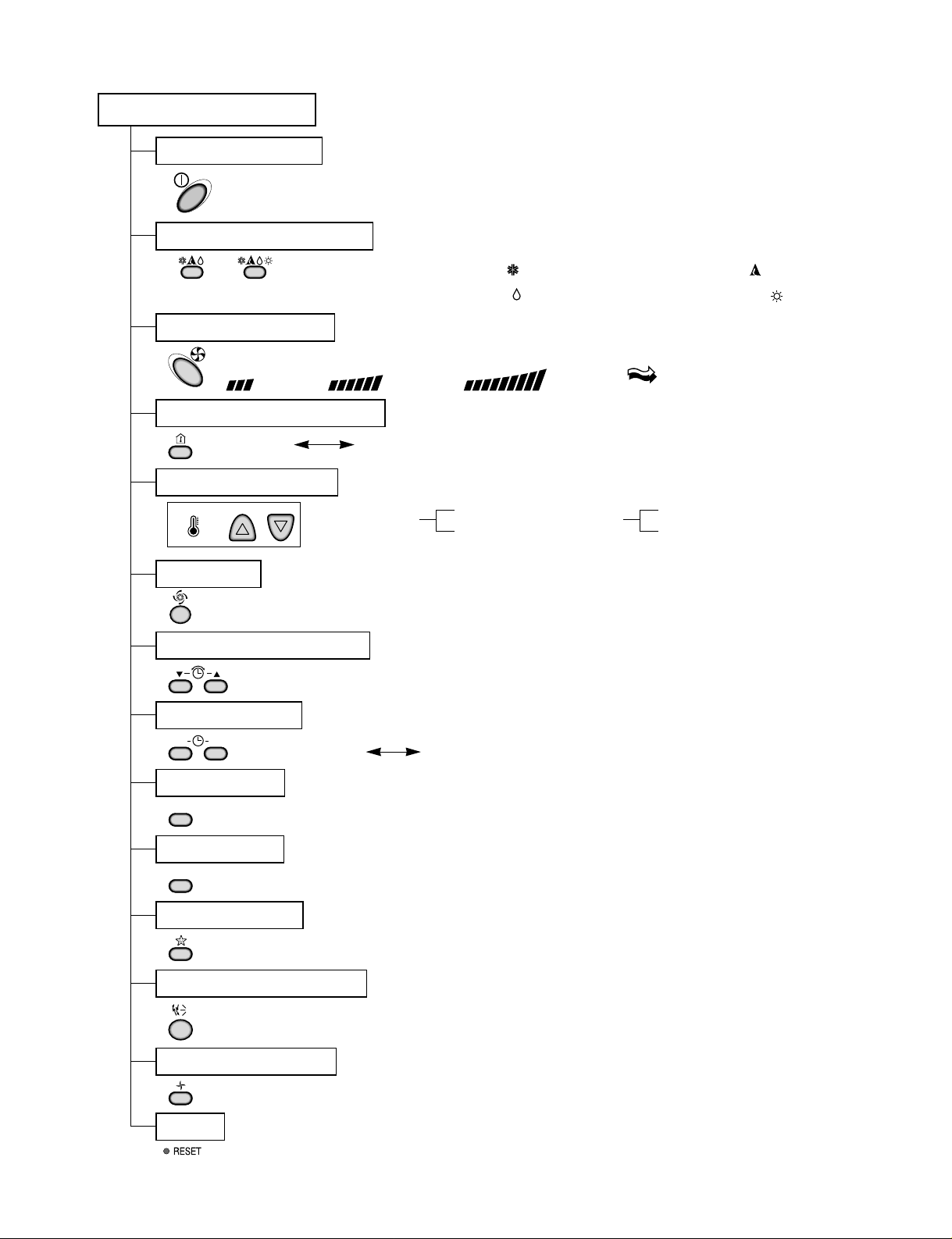
Remote Controller
Operation ON/OFF
Reset
Operation Mode Selection
Temperature Setting
Timer Selection
Timer Setting
JET COOL
Timer Cancel
Sleep Operation
Airflow Direction Control
(Cooling
model only)
(Heating
model only)
TEMPERATURE
LOWHIGH
Cooling Operation Mode.( )
Heating Operation Mode.( )
Auto Operation Mode.( )
Fan Operation Mode
Room, Temperature Display
Setting the Time or Timer
ON OFF
SET
CANCEL
Fan Speed Selection
(Low) (Med) (High) (CHAOS)
: (High: 39°C LOW : 11°C)
Down to 18°C
Up to 30°C
Cooling
: OFF, ON, OFF ON
: Cancel Sleep Mode, Timer ON or Timer OFF
: 1, 2, 3, 4, 5, 6, 7, Off Timer
: Fan Operates without cooling or heating.
Down to 16°C
Up to 30°C
Heating
Page 5
-5-
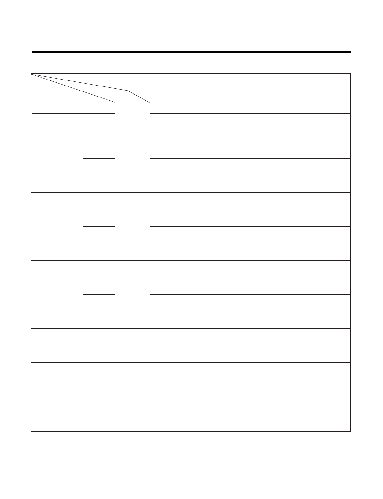
Product Specifications
Model Name
Item Unit
Cooling Capacity
Btu/h
12,000 12,000
Heating Capacity - 13,000
Moisture Removal l/h 1.5 1.5
Power Source Ø, V, Hz 1Ø, 220-240V, 50Hz
9.5 9.5
25 25
36 36
46 46
Cooling
W
1,190 1,200
Heating - 1,120
Running Cooling
A
5.4 5.5
Current Heating - 5.0
E.E.R. Cooling Btu/hW 10.1 10.0
C.O.P Heating - 3.4
13 13
26 26
888 x 287 x 170
770 x 540 x 245
9 9
34 35
Refrigerant (R22) g 740 830
Airflow Direction Control (Up & Down) § §
Remocon Type L.C.D Wireless
inch(mm)
1/4" (6.35)
1/2" (12.7)
Sleeping Operation § §
Drain Hose § §
Connecting Cable 1.0mm
2
Power Cord 1.0mm
2
Air Circulation
Noise Level
Input
m3/min
dB (A)¡ 3
Indoor
Outdoor
Indoor
Outdoor
Indoor
Outdoor
Indoor
Outdoor
Indoor
Outdoor
Liquid
Gas
Service Valve
Motor Output
Dimensions
(W¡¿H¡¿D)
Net. Weight
W
mm
kg
LS-L1260CL LS-L1260HL
SPEC. AT 230V
Page 6
-6-
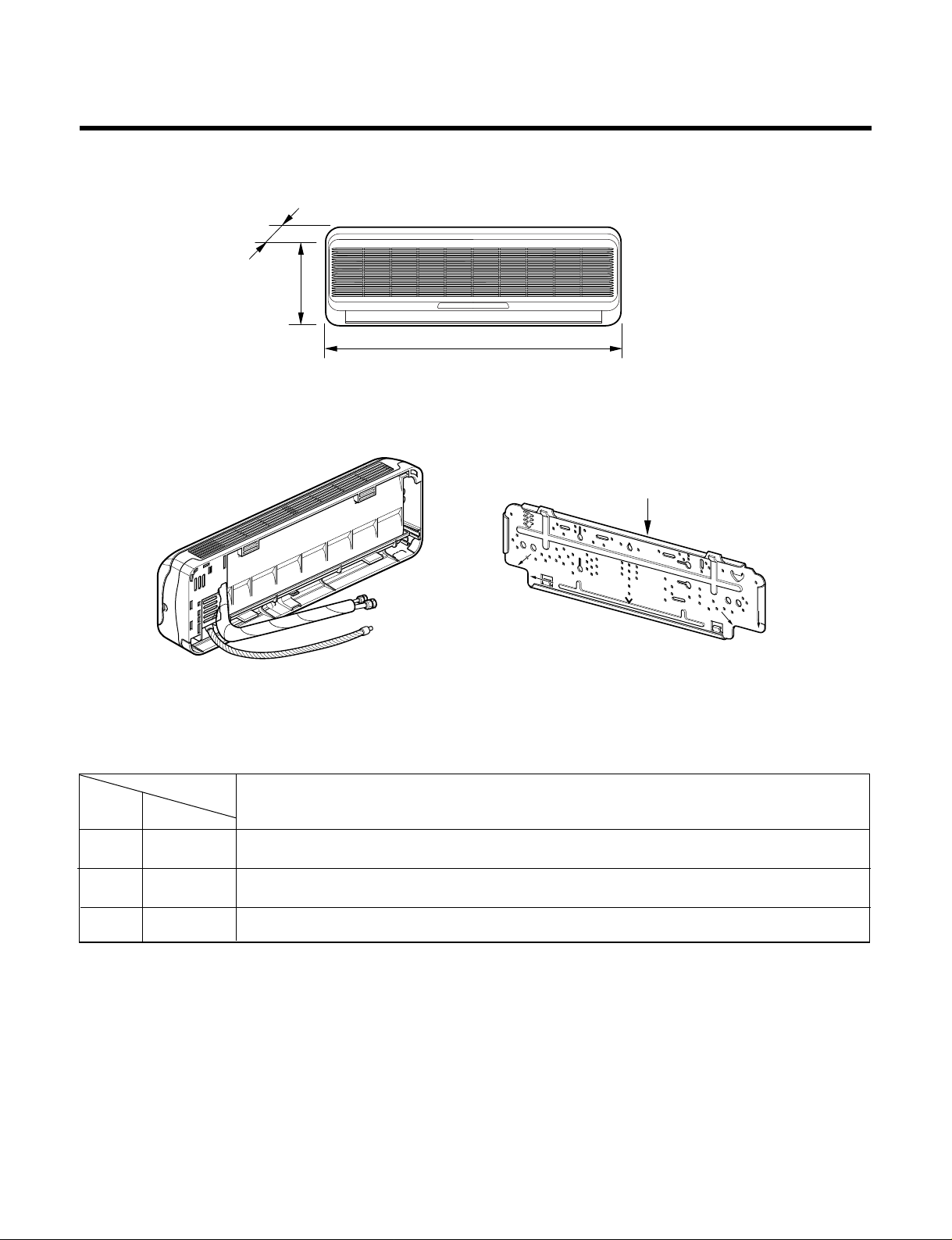
Installation plate
D
H
W
MODEL
DIM Unit
W mm 888
H mm 287
D mm 170
12K Btu Series
Dimensions
(1) Indoor Unit
Page 7
-7-
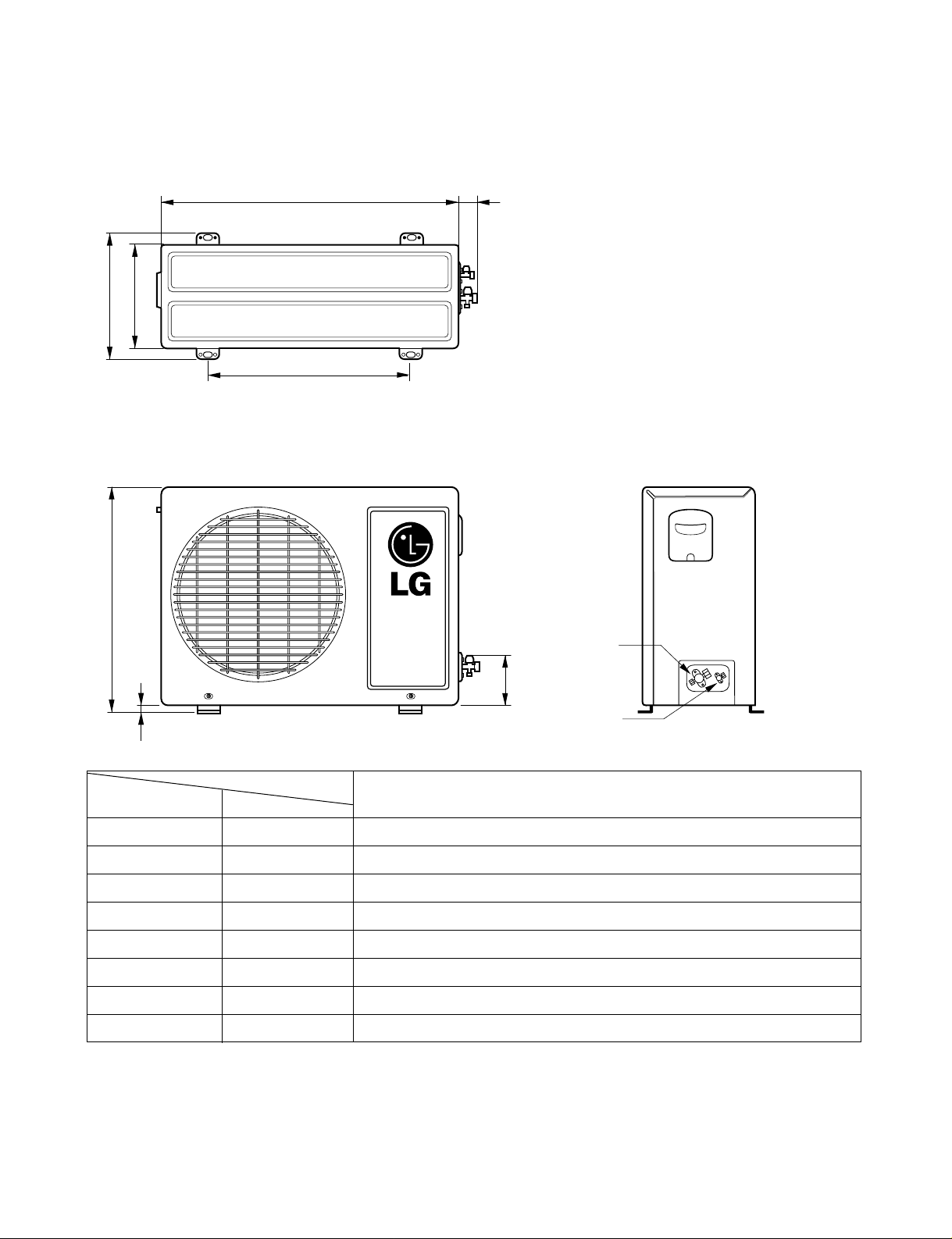
(2) Outdoor Unit
W
L2
L3
L1
D
H
L4
L5
Gas side
(3-way valve)
Liquid side
(2-way valve)
MODEL
12K Btu Series
DIM unit
W mm 770
H mm 540
D mm 245
L1 mm 287
L2 mm 64
L3 mm 518
L4 mm 10
L5 mm 100
Page 8

Refrigeration Cycle Diagram
-8-
Pipe size(Diameter:Ø)
MAX. Max
MODEL Piping length Elevation
Gas(inch) Liquid(inch)
(m) (m)
1/2" 1/4" 15 7
12K Btu SERIES
INDOOR UNIT OUTDOOR UNIT
HEAT
EXCHANGE
(EVAPORATOR)
LIQUID SIDE
2-WAY VALVE
GAS SIDE
3-WAY VALVE
(Heating Model only)
ACCUMU
LATOR
CHECK VALVE
CAPILLARY TUBE
COMPRESSOR
HEAT
EXCHANGE
(CONDENSER)
REVERSING
VALVE
(Heating Model Only)
COOLING
HEATING
Page 9
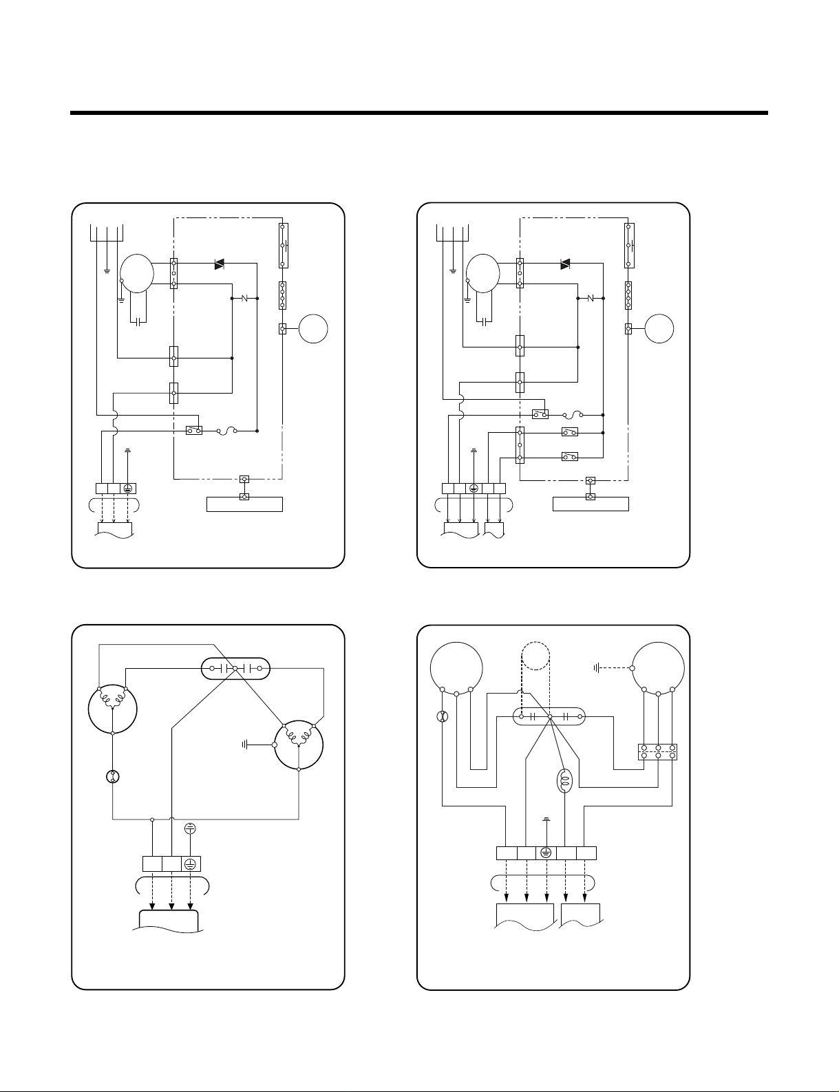
Wiring Diagram
-9-
3854A30077B
F
CH
BL
R S
C
COMP.
FAN
MOTOR
BL
CAPACITOR
RD
TO INDOOR UNIT
OUTDOOR WIRING DIAGRAM
RD
BR
OLP
BR
YL
TERMINAL
BLOCK
BL
1(L) 2(N)
1
GN/YL
BL
BR
BLACK
GN/YL
BL
BR
3854A30077A
INDOOR WIRING DIAGRAM
CN-DISP1
FUSE
AC250V/T2A
CN-TH1
TRIAC
SH-CAPA.
BL
BR
GN/YL
BR
YL
OR
BK
CN-TAB1
CN-MOTOR
CN-TAB2
RY-COMP.
ZNR
THERMISTOR
FORCED
OPERATION
AUTO
RESTART
REMOTE
CONTROL
MOTOR
MAIN PCB
ASM
DISPLAY PCB ASM
POWER
TO OUTDOOR UNIT
PILLAR
TERMINAL
BRBLGN/YL
BR
BL
GN/YL
1(L) 2(N
)
3
4
BL
CN-U/D
STEP
MOTOR
BL
BK
(RD)
BK
(RD)
BL
YL
YL
BR
RD
RD BL YL
GN/YL
BL BK
RD
BR
GN/YL
BL BL
GN/YL
PTC
3854A30077D
FAN
MOTOR
RD
BL
BR
C
S
R
COMP.
REVERSING
VALVE
OUTDOOR WIRING DIAGRAM
TERMINAL
BLOCK
TO INDOOR UNIT
OLP
H
C F
CAPACITOR
1(L) 2(N) 3 4
3854AR6093Y
INDOOR WIRING DIAGRAM
CN-DISP1
FUSE
AC250V/T2A
CN-TH1
TRIAC
SH-CAPA.
BL
BR
GN/YL
BR
YL
OR
BK
CN-TAB1
CN-MOTOR
CN-TAB2
CN-4WAY
RY-COMP.
RY-4WAY
RY-FAN
ZNR
THERMISTOR
FORCED
OPERATION
AUTO
RESTART
REMOTE
CONTROL
MOTOR
MAIN PCB
ASM
DISPLAY PCB ASM
POWER
TO OUTDOOR UNIT
PILLAR
TERMINAL
BR
BL
BK
RD
GN/YL
BR
BL
BK
RD
GN/YL
1(L) 2(N
)
3 4
3
4
BL
BR
CN-U/D
STEP
MOTOR
1. LS-L1260CL 2. LS-L1260HL
1. LS-L1260CL 2. LS-L1260HL
(1) Indoor Unit
(2) Outdoor Unit
Page 10
Operation Details
1. MAIN UNIT FUNCTION
• DISPLAY
1) C/O Model
Operation Indicator
• On while in appliance operation, off while in appliance pause
• Flashing while in disconnection or short in Thermistor (3 sec off / 0.5 sec on)
Sleep Timer Indicator
• On while in sleep timer mode, off when sleep timer cancel or appliance operation pause
Timer Indicator
• On while in timer mode (on/off), off when timer mode is completed or canceled.
Comp. Running Incidator
• While in appliance operation, on while in outdoor unit compressor running, off while in compressor off
2) H/P Model
Operation Indicator
• On while in appliance operation, off while in appliance pause
• Flashing while in disconnection or short in Thermistor (3 sec off / 0.5 sec on)
Sleep Timer Indicator
• On while in sleep timer mode, off when sleep timer cancel or appliance operation pause
Timer Indicator
• On while in timer mode (on/off), off when timer mode is completed or canceled
Defrost Indicator
• Off except when hot start during heating mode operation or while in defrost control
■ Cooling Mode Operation
• When the intake air temperature reaches 0.5°C below the setting temp, the compressor and the outdoor fan
stop.
• When it reaches 0.5°C above the setting temp, they start to operate again.
Compressor ON Temp ➲ Setting Temp+0.5°C
Compressor OFF Temp ➲ Setting Temp-0.5°C
• While in compressor running, operating with the airflow speed set by the remote control. While in compressor
not running, operating with the low airflow speed regardless of the setting.
■ Healthy Dehumidification Mode
• When the dehumidification operation input by the remote control is received, the intake air temperature is
detected and the setting temp is automatically set according to the intake air temperature.
26°C ≤ Intake Air Temp ➲ 25°C
24°C ≤ Intake Intake Air Temp<26°C ➲ Intake Air Temp-1°C
18°C ≤ Intake Intake Air Temp<24°C ➲ Intake Air Temp-0.5°C
Intake Air Temp<18°C ➲ 18°C
-10-
Page 11

• While in compressor off, the indoor fan repeats low airflow speed and pause.
• While the intake air temp is between compressor on temp. and compressor off temp., 10-min dehumidification operation and 4-min compressor off repeat.
Compressor ON Temp. ➲ Setting Temp+0.5°C
Compressor OFF Temp. ➲ Setting Temp-0.5°C
• In 10-min dehumidification operation, the indoor fan operates with the low airflow speed.
■ Heating Mode Operation
• When the intake air temp reaches +3°…above the setting temp, the compressor is turned off. When below
the setting temp, the compressor is turned on.
Compressor ON Temp. ➲ Setting Temp.
Compressor OFF Temp. ➲ Setting Temp.+3°C
• While in compressor on, the indoor fan is off when the indoor pipe temp. is below 20°C, when above 28°C , it
operates with the low or setting airflow speed. When the indoor pipe temp is between 20°C and 28°C, it operates with Super-Low(while in sleep mode, with the medium airflow speed).
• While in compressor off, the indoor fan is off when the indoor pipe temp is below 33°C, when above 35°C , it
operates with the low airflow speed.
• If overloaded while in heating mode operation, in order to prevent the compressor from OLP operation, the
outdoor fan is turned on/off according to the indoor pipe temp.
• While in defrost control, both of the indoor and outdoor fans are turned off.
■ Defrost Control
• While in heating mode operation in order to protect the evaporator pipe of the outdoor unit from freezing,
reversed to cooling cycle to defrost the evaporator pipe of the outdoor unit.
• After 40 min heating mode operation, at 4 min interval, whether to carry out defrost control or not and the time
of defrost control are determined according to the following conditions.
1) While in heating mode operation, the maximum of the indoor pipe temperature is measured and it is com-
pared with the present indoor pipe temperature to get the difference of the indoor pipe temperatures (=the
maximum temperature of indoor pipe ? the present temperature of indoor pipe), according to which, whether
to carry out defrost control or not is determined.
2) According to the need of defrost control shown above and the elapsed time of heating mode operation at that
moment, the defrost control time is determined.
3) When the determined time of defrost control is below 7 min, heating mode operation continues without carry-
ing out defrost control. According to the procedure stated above, the determination is made again. When the
defrost control time is 7 min or longer, defrost control is then carried out.
• While in defrost control, the minimum temp of the indoor pipe is measured and it is compared with the present
temp of the indoor pipe to get the difference of the indoor pipe temperatures (=the present temperature of the
indoor pipe ? the minimum temperature of the indoor pipe). When the difference is 5°C or higher, defrost control is completed and heating mode operation is carried out.
• While in defrost control, if the defrost time determined before the start of defrost control is completed, defrost
control stops and heating mode operation is carried out regardless of the above condition.
• When the indoor pipe temp is 42°C or above, defrost control is not carried out even if the condition is one of
the defrost conditions above.
• While in defrost control, the compressor is on and the indoor fan, the outdoor fan, and the 4 way valve are off.
-11-
Page 12

-12-
■ Fuzzy Operation (C/O Model)
• According to the temperature set by Fuzzy rule, when the intake air temp is 0.5°C or more below the setting
temp, the compressor is turned off. When 0.5°C or more above the setting temp, the compressor is turned on.
Compressor ON Temp ➲ Setting Temp + 0.5°C
Compressor OFF Temp ➲ Setting Temp + 0.5°C
• At the beginning of Fuzzy mode operation, the setting temperature is automatically selected according to the
intake air temp at that time.
26°C ≤ Intake Air Temp ➲ 25°C
24°C ≤ Intake Air Temp < 26°C ➲ Intake Air Temp + 1°C
22°C ≤ Intake Air Temp < 24°C ➲ Intake Air Temp + 0.5°C
18°C ≤ Intake Air Temp < 22°C ➲ Intake Air Temp
Intake Air Temp<18°C ➲ 18°C
• When the Fuzzy key (Temperature Control key) is input after the initial setting temperature is selected, the
Fuzzy key value and the intake air temperature at that time are compared to select the setting temperature
automatically according to the Fuzzy rule.
• While in Fuzzy operation, the airflow speed of the indoor fan is automatically selected according to the
temperature.
■ Fuzzy Operation (H/P Model)
• When any of operation mode is not selected like the moment of the power on or when 3 hrs has passed since
the operation off, the operation mode is selected.
• When determining the operation mode, the compressor, the outdoor fan, and the 4 way valve are off and only
the indoor fan is operated for 15 seconds. Then an operation mode is selected according to the intake air
temp at that moment as follows.
24°C ≤ Inatake Air Temp ➲ Fuzzy Operation for Cooling
21°C ≤ Inatake Air Temp<24°C ➲ Fuzzy Operation for Dehumidification
Inatake Air Temp<21°C ➲ Fuzzy Operation for Heating
• If any of the operation modes among cooling / dehumidification / heating mode operations is carried out for 10
sec or longer before Fuzzy operation, the mode before Fuzzy operation is operated.
1) Fuzzy Operation for Cooling
• According to the setting temperature selected by Fuzzy rule, when the intake air temp is 0.5°C or more below
the setting temp, the compressor is turned off. When 0.5°C or more above the setting temp, the compressor
is turned on.
Compressor ON Temp ➲ Setting Temp +0.5°C
Compressor OFF Temp ➲ Setting Temp + 0.5°C
• At the beginning of Fuzzy mode operation, the setting temperature is automatically selected according to the
intake air temp at that time.
26°C≤ Intake Air Temp ➲ 25°C
24°C≤ Intake Air Temp<26°C ➲ Intake Air Temp + 1°C
22°C≤ Intake Air Temp<24°C ➲ Intake Air Temp + 0.5°C
18°C≤ Intake Air Temp<22°C ➲ Intake Air Temp
Intake Air Temp<18°C ➲ 18°C
• When the Fuzzy key (Temperature Control key) is input after the initial setting temperature is selected, the
Fuzzy key value and the intake air temperature at that time are compared to select the setting temperature
automatically according to the Fuzzy rule.
• While in Fuzzy operation, the airflow speed of the indoor fan is automatically selected according to the temperature.
Page 13

-13-
2) Fuzzy Operation for Dehumidification
• According to the setting temperature selected by Fuzzy rule, when the intake air temp is 0.5°C or more below
the setting temp, the compressor is turned off. When 0.5°C or more above the setting temp, the compressor
is turned on.
Compressor ON Temp ➲ Setting Temp + 0.5°C
Compressor OFF Temp ➲Setting Temp+0.5°C
• At the beginning of Fuzzy mode operation, the setting temperature is automatically selected according to the
intake air temp at that time.
26°C ≤ Intake Air Temp ➲ 25°C
24°C ≤ Intake Air Temp<26°C ➲ Intake Air Temp+1°C
22°C ≤ Intake Air Temp<24°C ➲ Intake Air Temp+0.5°C
18°C ≤ Intake Air Temp<22°C ➲ Intake Air Temp
Intake Air Temp<18°C ➲ 18°C
• When the Fuzzy key (Temperature Control key) is input after the initial setting temperature is selected, the
Fuzzy key value and the intake air temperature at that time are compared to select the setting temperature
automatically according to the Fuzzy rule.
• While in Fuzzy operation, the airflow speed of the indoor fan repeats the low airflow speed or pause as in
dehumidification operation.
3) Fuzzy Operation for Heating
• According to the setting temperature selected by Fuzzy rule, when the intake air temp is 3°C or more above
the setting temp, the compressor is turned off. When below the setting temp, the compressor is turned on.
Compressor ON Temp ➲ Setting Temp
Compressor OFF Temp ➲Setting Temp + 3°C
• At the beginning of Fuzzy mode operation, the setting temperature is automatically selected according to the
intake air temp at that time.
20°C≤Intake Air Temp ➲ Intake Air Temp + 0.5°C
Intake Air Temp<20°C ➲ 20°C
• When the Fuzzy key (Temperature Control key) is input after the initial setting temperature is selected, the
Fuzzy key value and the intake air temperature at that time are compared to select the setting temperature
automatically according to the Fuzzy rule.
• While in Fuzzy operation, the airflow speed of the indoor fan is set to the high or the medium according to the
intake air temperature and the setting temperature.
■ Airflow Speed Selection
• The airflow speed of the indoor fan is set to high, medium, low, or chaos (auto) by the input of the airflow
speed selection key on the remote control.
■ On-Timer Operation
• When the set time is reached after the time is input by the remote control, the appliance starts to operate.
• The timer LED is on when the on-timer is input. It is off when the time set by the timer is reached.
• If the appliance is operating at the time set by the timer, the operation continues.
Page 14

-14-
■ Off-Timer Operation
• When the set time is reached after the time is input by the remote control, the appliance stops operating.
• The timer LED is on when the off-timer is input. It is off when the time set by the timer is reached.
• If the appliance is on pause at the time set by the timer, the pause continues.
■ Off-Timer <=> On-Timer Operation
• When the set time is reached after the on/off time is input by the remote control, the on/off-timer operation is
carried out according to the set time.
■ Sleep Timer Operation
• When the sleep time is reached after <1,2,3,4,5,6,7,0(cancel) hr> is input by the remote control while in appli-
ance operation, the operation of the appliance stops.
• While the appliance is on pause, the sleep timer mode cannot be input.
• While in cooling mode operation, 30 min later since the start of the sleep timer, the setting temperature
increases by 1°C. After another 30 min elapse, it increases by 1°C again.
• When the sleep timer mode is input while in cooling cycle mode, the airflow speed of the indoor fan is set to the
low.
• When the sleep timer mode is input while in heating cycle mode, the airflow speed of the indoor fan is set to
the medium.
■ Chaos Swing Mode
• By the Chaos Swing key input, the upper/lower vane automatically operates with the Chaos Swing or they are
fixed to the desired direction.
• While in Chaos Swing mode, the angles of cooling and heating cycle operations are different.
■ Chaos Natural Wind Mode
• When the Chaos Natural Wind mode is selected and then operated, the high, medium, or low speed of the air-
flow mode is operated for 2~15 sec. randomly by the Chaos Simulation.
CLOSED
OPEN
< Cooling Mode >
7°
CLOSED
OPEN
< Heating Mode >
7°
Page 15
-15-
■ Jet Cool Mode Operation (C/O Model)
• If the Jet Cool key is input at any operation mode while in appliance operation, the Jet Cool mode operates.
• In the Jet Cool mode, the indoor fan is operated at super-high speed for 30 min at cooling mode operation.
• In the Jet Cool mode operation, the room temperature is controlled to the setting temperature, 18°C
• When the sleep timer mode is input while in the Jet Cool mode operation, the Jet Cool mode has the priority.
• When the Jet Cool key is input, the upper/lower vanes are reset to those of the initial cooling mode and then
operated in order that the air outflow could reach further.
■ Jet Cool Mode Operation (H/P Model)
• While in heating mode or Fuzzy operation, the Jet Cool key cannot be input. When it is input while in the other
mode operation (cooling, dehumidification, ventilation), the Jet Cool mode is operated.
• In the Jet Cool mode, the indoor fan is operated at super-high speed for 30 min at cooling mode operation.
• In the Jet Cool mode operation, the room temperature is controlled to the setting temperature, 18°C.
• When the sleep timer mode is input while in the Jet Cool mode operation, the Jet Cool mode has the priority.
• When the Jet Cool key is input, the upper/lower vanes are reset to those of the initial cooling mode and then
operated in order that the air outflow could reach further.
■ Auto Restarting Operation
• When the power is restored after a sudden power failure while in appliance operation, the mode before the
power failure is kept on the memory and the appliance automatically operates in the mode on the memory.
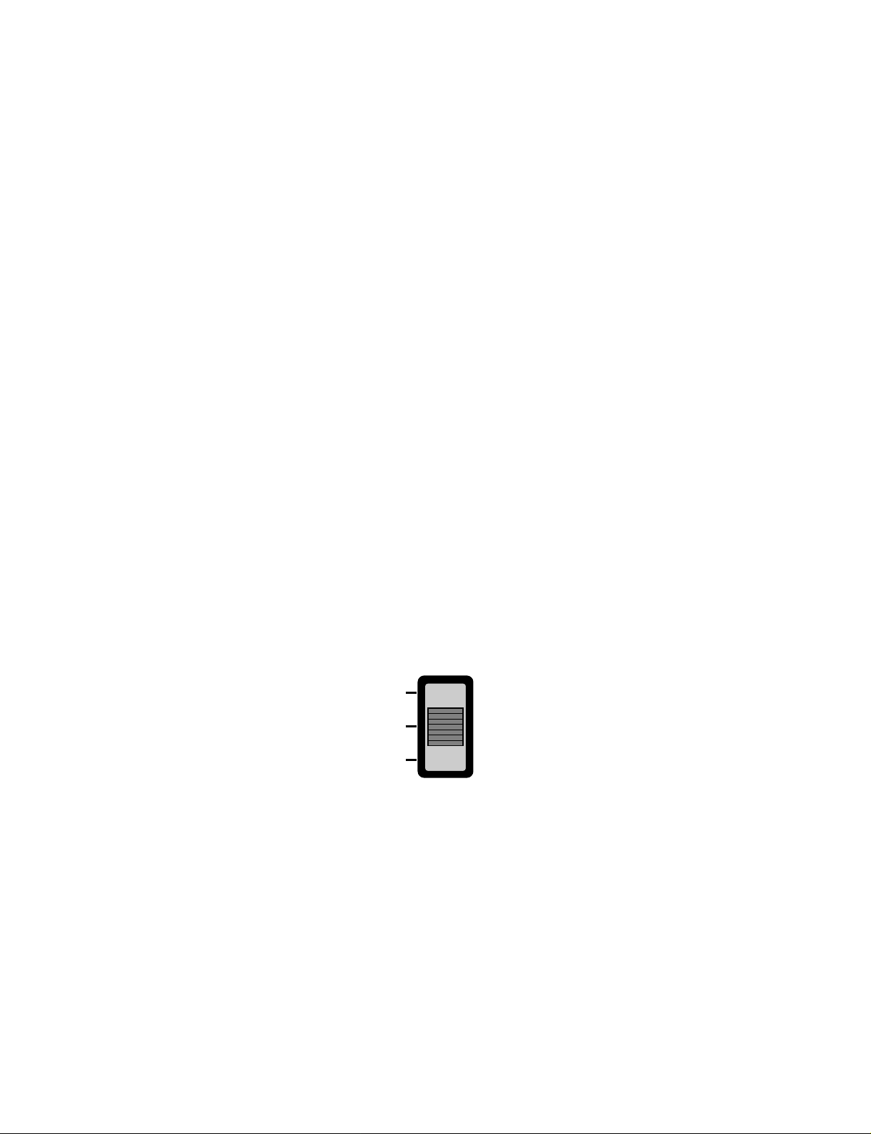
• The slide switch on the main unit of the appliance should be on the Auto Restar ting position in order that the
Auto Restarting operation is available.
• Operation Mode that is kept on the memory
- State of Operation ON/OFF
- Operation Mode/Setting Temp/Selected Airflow Speed
- Sleep Timer Mode/Remaining Time of Sleep Timer (unit of hour)
• If no input by the remote control or no switching of the slide switch within 7 hr after the appliance operates by
the Auto Restarting operation, the appliance is forced to stop at the moment of 7-hr elapse.
Slide Switch
FORCED
OPERATION
AUTO
RESTART
REMOTE
CONTROL
■ Forced Operation (C/O Model)
• To operate the appliance by force in case that the remote control is lost, the forced operation selection switch is
on the main unit of the appliance to operate the appliance in the standard conditions.
• When the power is supplied while the slide switch is on the forced operation position, or when the slide switch
position is switched to the Auto Restarting position (or test operation) or switched from the remote control position to the forced operation position while the power is on, the forced operation is carried out.
• When the slide switch position is switched from the forced operation position to the Auto Restarting position or
the remote control position, the forced operation is canceled and the appliance stops operating.
• The forced operation is carried out in cooling mode with the setting temperature 22°C and the high speed of
airflow.
• While in forced operation, the key input by the remote control has no effect and the buzzer sounds 10 times to
indicate the forced operation.
Page 16

-16-
■ Forced Operation (H/P Model)
• To operate the appliance by force in case that the remote control is lost, the forced operation selection switch
is on the main unit of the appliance to operate the appliance in the standard conditions.
• When the power is supplied while the slide switch is on the forced operation position, or when the slide switch
position is switched to the Auto Restarting (or test operation) position or switched from the remote control
position to the forced operation position while the power is on, the forced operation is carried out.
• When the slide switch position is switched from the forced operation position to the Auto Restarting position or
the remote control position, the forced operation is canceled and the appliance stops operating.
• The forced operation is carried out in cooling mode with the setting temperature 22°C and the high speed of
airflow.
• In the forced operation mode, the indoor fan is operated at low speed for around 15 sec and then the operation condition is set according to the intake air temperature as follows.
24°C≤Intake Air Temp ➲ Cooling Mode Operation, 22°C, High Speed
21°C≤Intake Air Temp<24°C ➲ Dehumidification Operation, 23°C, High Speed
Intake Air Temp<21°C ➲ Heating Mode Operation, 24°C, High Speed
• While in forced operation, the key input by the remote control has no effect and the buzzer sounds 10 times to
indicate the forced operation.
■ Remote Control Operation Mode
• When the remote control is selected by the slide switch on the main unit, the appliance operates according to
the input by the remote control.
■ Protection of the evaporator pipe from frosting
• If the indoor pipe temp is below 0°C in 7 min. after the compressor operates without any pause while in cooling cycle operation mode, the compressor and the outdoor fan are turned off in order to protect the indoor
evaporator pipe from frosting.
• When the indoor pipe temp is 7°C or higher after 3 min. pause of the compressor, the compressor and the
outdoor fan is turned on according to the condition of the room temperature.
■ Buzzer Sounding Operation
• When the appliance-operation key is input by the remote control, the short "beep-beep-" sounds.
• When the appliance-pause key is input by the remote control, the long "beep—" sounds.
• When a key is input by the remote control while the slide switch on the main unit of the appliance is on the
forced operation position, the error sound "beep-beep-beep-beep-beep-" is made 10 times to indicate that the
remote control signal cannot be received.
Page 17
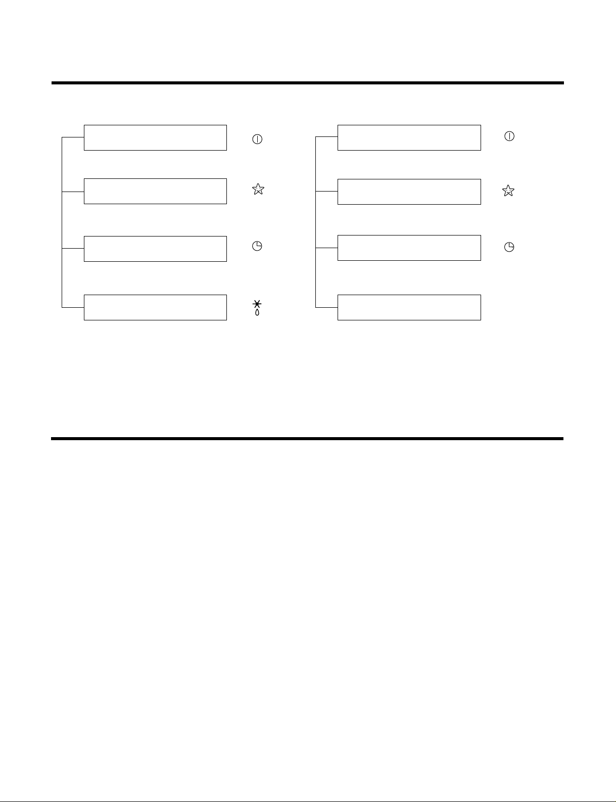
Display Function
1. Heating Model 2. Cooling Model
• Cooling, Soft Dry, Fan, Heating • Cooling, Soft Dry, Fan
• Sleep Mode • Sleep Mode
• Timer Mode • Timer Mode
• Hot-start, Defrost
Self-diagnosis Function
■ Thermistor Error Indicator
• When the indoor pipe sensor or the room temperature sensor is open or is shorted, the error is indicated.
• To indicate the error, the operation LED (or the cooling LED) flashed at 3 sec interval.
• When the error is cleared, the LED stops flashing, the operation (or cooling) LED is on.
• While in appliance pause, the error is not indicated.
Operation Indicator
Timer Indicator
Sleep Timer Indicator
Defrost Indicator
-17-
Operation Indicator
Timer Indicator
Sleep Timer Indicator
Compressor on Indicator
OUT
DOOR
Page 18
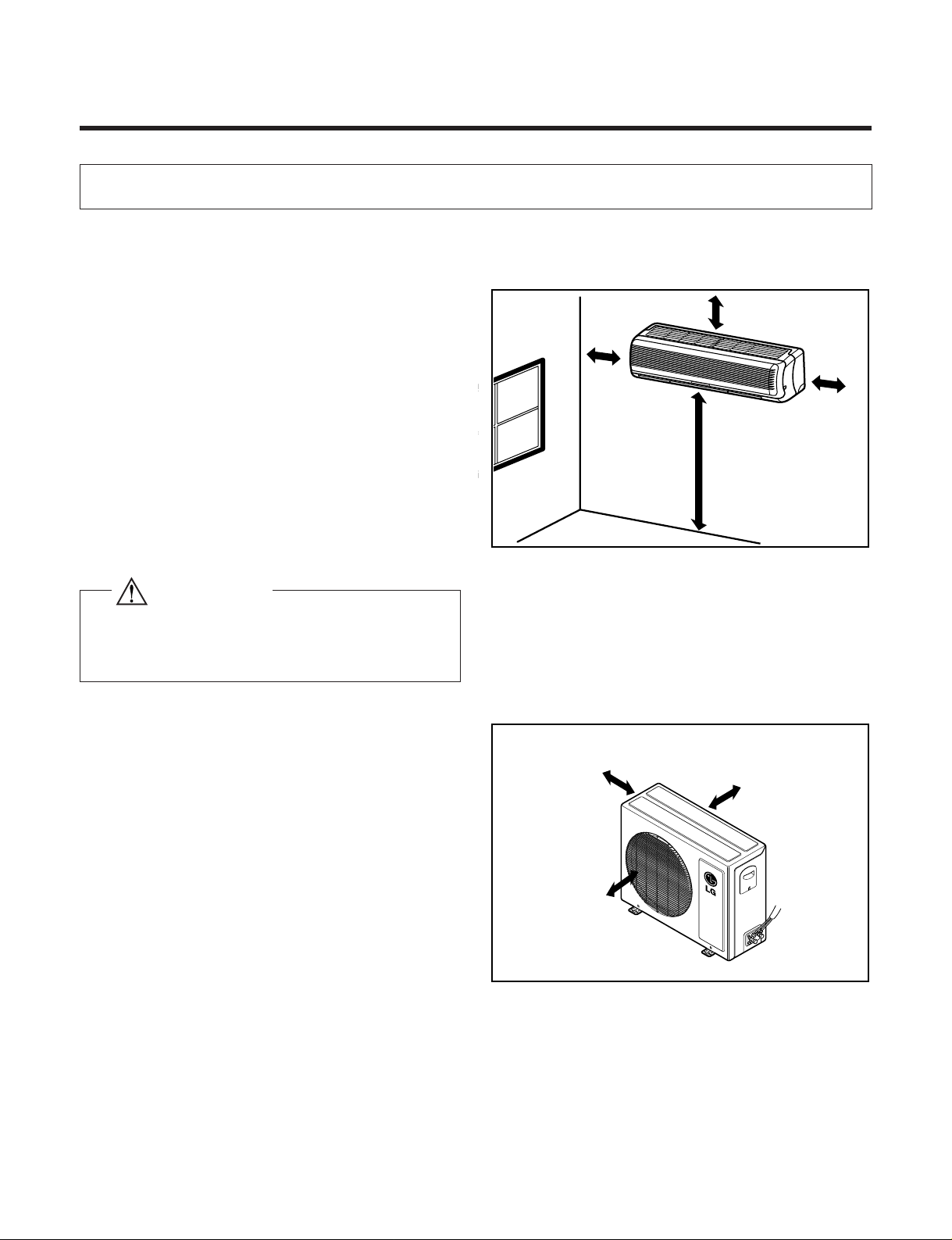
Installation
1. Installation of indoor, Outdoor unit
-18-
More than 2.3 m
More than 5 cm
More than
5 cm
More than
5 cm
More than 10 cm
More than 10 cm
More than 70 cm
1) Selection of the best location
1. Indoor unit
2. Outdoor unit
• There should not be any heat source or steam
near the unit.
• There should not be any obstacles to prevent the
air circulation.
• A place where air circulation in the room will be
good.
• A place where drainage can be easily obtained.
• A place where noise prevention is taken into consideration.
• Do not install the unit near the door way.
• Ensure the spaces indicated by arrows from the
wall, ceiling, fence or other obstacles.
• If an awning is built over the unit to prevent
direct sunlight or rain exposure, be careful
that heat radiation from the condenser is not
restricted.
• There should not be any animals or plants
which could be affected by hot air discharged.
• Ensure the correct distance is left from the
wall, ceiling, fence, or other obstacles as indicated in the diagram.
Install the indoor unit on the wall where the height
from the floor is more than 2.3 meters.
CAUTION
Page 19
-19-
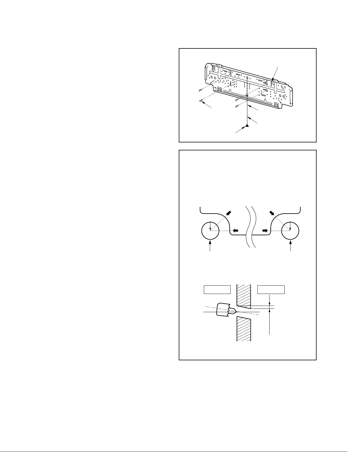
5-7mm
Indoor Outdoor
WALL
ø70mm
A
A
A
A
Center
Right rear pipingLeft rear piping
Center
ø70mm
Installation plate
Marking-off line
Thread
Weight
Type "A" screw
2) Indoor Unit Installation
The mounting wall should be strong and solid enough
to protect it from the vibration.
1.Mount the installation plate on the wall with four
Type "A" screws.
(if mounting the unit on the concrete wall, consider
using anchor bolts.)
• Always mount the Installation plate horizontally by
aligning the marking-off line by means of the
thread and a level.
2. Drill the piping hole with 70mm dia. holecore
drill.
• Line according to the arrows marked on lower the
left and the right side of the Installation Plate.
The meeting point of the extended line is the center of the hole.
• Drill the Piping hole at either the right or the left
and the hole should be slightly slanted to the outdoor side.
The lower left and right side of Installation
Plate
12K Btu
Page 20

-20-
2. Piping and Drainage of Indoor Unit
1) Preparation of Piping
1. Cut the pipes and the cable.
• Use the accessory piping kit or the pipes purchased locally.
• Measure the distance between the indoor and the
outdoor unit.
• Cut the pipes a little longer than measured distance.
• Cut the cable 1.5m longer than the length of the
pipe.
2. Remove burrs.
• Remove burrs from cut edges of pipes.
• Turn the pipe end toward down to avoid the metal
powder entering the pipe.
Caution:
If burrs are not removed, they may cause a gas leakage.
3. Flaring the pipes.
• Insert the flare nuts, mounted on the connection
ports of both indoor and outdoor unit, onto the
copper pipes. (When the flare nuts are removed
from the indoor unit.) Some gas may leak, as
some gas is charged to prevent the inside of the
pipe from rusting.
• Fit the copper pipe end into the Bar of flare tool
about 0~1.0mm higher.
(See illustration)
• Flare the pipe ends.
4. Tape the flaring portion to protect it from the
dust or damages.
90
Slanted Rough
Pipe cutter
Pipe
Reamer
Point down
"A"
Bar
Bar
Clamp handle
Red arrow mark
Cone
Yoke
Handle
Copper pipe
Inclined Cracked Uneven
thickness
Surface
damaged
= Improper flaring =
When properly flared, the internal surface of the flare will
evenly shine and be of even thickness.
After the flare part comes into contact with the connectors, carefully check the flare finish.
"A"; ø15.88 mm (5/8")
¡ 0~1.0 mm
ø12.7 mm (1/2") ¡ 0~0.5 mm
ø9.52 mm (3/8") ¡ 0~0.5 mm
ø6.35 mm (1/4") ¡ 0~0.5 mm
Page 21

-21-
To remove the holder,
press the bottom of
chassis near the holder
upward and pull the tab
out of its hole.
Tubing holder
Pull
Press
2
1
,
Drain hose
Indoor Outdoor
Connecting cable
Connecting
piping
Drain pipe
Indoor unit tubing Flare nut
Spanner
Torque wrench
Plastic bands
Drain hose
Adhesive
Drain pipe
Insulation material
Pipings
2)
Connection of Pipings
1. Remove the tubing holder.
2. Route the drain hose and the indoor tubing.
For right rear piping
3. Insert the piping, the connecting cables and the
drain pipe through the piping hole on the wall.
4. Connect the piping and the indoor tubing, and
drain hose and drain pipe.
• Don't connect the cable to the indoor unit.
• Wrap the insulation material around the connecting portion.
• Glue up the connection portion of drain hose and
drain pipe.
Pipe Size Torque
Liquid Side (1/4") 1.8kg.m
Gas Side (3/8") 4.2kg.m
Gas Side (1/2") 5.5kg.m
Page 22

-22-
Tubing holder
Hook
1
Push
2
Taping
Conecting
cable
Gas side
piping
Drain hose
Liquid side
piping
Connecting
cable
Drain hose
Press the lower left and right side of the unit against
the Installation Plate until the hooks engage with their
slots (sound click).
5. Bend the tubing as shown in the figure and bind
the piping, the connecting cables and the drain
hose altogether.
• Make a small loop for easy connection later.
6. Wrap the tubing, the drain hose and the connecting cable with tape.
7. Indoor unit installation
• Hook the indoor unit onto the upper portion of the
installation plate. (Engage the two hooks of the
rear top of the indoor unit with the upper edge of
the installation plate.)
Ensure the hooks are properly seated on the
installation plate by moving it in left and right.
CAUTION
Take care to arrange the piping, drain hose and
cables as the feature 7 page for inser ting it into the
indoor unit and mount the indoor unit on the installation plate.
CAUTION
When install, make sure that the remaining parts
must be removed clearly so as not to damage the
piping and drain hose, especially power cord and
connecting cable.
Page 23

-23-
Installation plate
Pull
Pull
To remove the holder,
press the bottom of
chassis near the holder
upward and pull the tab
out of its hole.
Tubing holder
Pull
Press
2
1
Indoor unit tubing Flare nut
Spanner
Torque wrench
Plastic bands
Drain hose
Adhesive
Drain pipe
Insulation material
Pipings
Taping
Indoor Outdoor
Connecting cable
Connecting
piping
Drain pipe
Drain hose
For left rear piping
3. Insert the connecting cables, the drain pipe and
connecting piping through the piping hole on
the wall.
4. Connect the piping and the indoor tubing, and
drain hose and drain pipe and place the drain
pipe into the chassis.
• Don't connect the cable to the indoor unit.
• Make a small loop for easy connection later.
• Glue up the connection portion of drain hose and
drain pipe.
5. Bend the drain hose and bind the drain hose,
the piping and the connecting cables altogether.
Pipe Size Torque
Liquid Side (1/4") 1.8kg.m
Gas Side (3/8") 4.2kg.m
Gas Side (1/2") 5.5kg.m
Page 24

-24-
Connecting
cable
Drain hose
Indoor/outdoor
connecting cable
Connecting
cable
Taping
Gas side piping
Liquid side piping
Drain hose
Press the lower left and right side of the unit against the
Installation Plate until the hooks engage with their slots
(sound click).
6. Wrap the insulation material around the connecting portion.
7. Wrap the tubing, the drain hose and the connecting cable with tape.
8. Indoor unit installation
• Hook the indoor unit onto the upper portion of
installation plate. (Engage the two hooks of the
rear top of the indoor unit with the upper edge of
the installation plate.)
Ensure the hooks are properly seated on the
installation plate by moving it left and right.
CAUTION
Take care to arrange the piping, drain hose and
cables as the figure 7 page for inserting it into the
indoor unit and mount the indoor unit on the installation plate.
Page 25

-25-
Outdoor unit
Liquid side piping
(Smaller Dia.)
Torque wrench
Gas side piping
(Bigger Dia.)
1) Connecting the piping to the Outdoor
unit
1. Align the center of the piping and sufficiently
tighten the flare nut with fingers.
2. Finally, tighten the flare nut with torque wrench
until the wrench clicks.
• When tightening the flare nut with torque wrench,
ensure the direction for tightening follows the arrow
on the wrench.
CAUTION
After the confirmation of the above conditions, prepare the wiring as follows:
1) Never fail to have an individual power specialized for the air conditioner. As for the method of wiring,
be guided by the circuit diagram pasted on the inside of control box cover.
2) Provide a circuit breaker switch between power source and the unit.
3) The screw which fasten the wiring in the casing of electrical fittings are liable to come loose from
vibrations to which the unit is subjected during the course of transportation. Check them and make
sure that they are all tightly fastened. (If they are loose, it could give rise to burn-out of the wires.)
4) Specification of power source.
5) Confirm that electrical capacity is sufficient.
6) See to it that the starting voltage is maintained at more than 90 percent of the rated voltage marked
on the name plate.
7) Confirm that the cable thickness is as specified in the power sources specification.
(Particularly note the relation between cable length and thickness.)
8) Never fail to equip a leakage breaker where it is wet or moist.
9) The following troubles would be caused by voltage drop-down.
• Vibration of a magnetic switch, damage on the contact point there of, fuse breaking, disturbance to the nor-
mal function of a overload protection device.
• Proper starting power is not given to the compressor.
3. Connecting Piping and Cable to the outdoor unit
Pipe Size Torque
Liquid Side (1/4") 1.8kg.m
Gas Side (3/8") 4.2kg.m
Gas Side (1/2") 5.5kg.m
Page 26

Outdoor unit
Over 5mm
Terminal block
(Pillar terminal)
Holder for
power supply
cord
Cover control
Connecting cable
-26-
2)
Connection of the cable
1. Remove the cover control from the unit by loosening the screw.
Connect the wires to the terminals on the control
board individually as the following.
2. Secure the cable onto the control board with the holder
(clamper).
3. Refix the cover control to the original position with the
screw.
4. Use a recognized circuit breaker 16A between the power
source and the unit. A disconnection device to adequately
disconnect all supply lines must be fitted.
1(L)Terminals on the outdoor unit
Terminals on the outdoor unit
Terminals on the indoor unit
Terminals on the indoor unit
1(L)
1(L)
1(L)
2(N)
2(N)
2(N)
3 4
3
4
2(N)
BROWN BLUE G/Y BLACK
RED
BROWN BLUE G/Y
RED
BROWN
BROWN BLUE BLACK
BLACK
G/Y RED
REDG/Y
BLUE
BROWN
BLUE
GREEN/YELLOW
BROWN BLUE
GREEN/YELLOW
1) Cooling only type
2) Cooling & Heating type
The power cord connected to the indoor unit should
be complied with the following specifications (Type
H05VV-F approved by HAR or SA).
The connecting cable connected to the indoor and
outdoor unit should be complied with the following
specifications (Rubber insulation, type H07RN-F
approved by HAR or SA).
NORMAL CROSSSECTIONAL AREA
1.0mm
2
NORMAL CROSSSECTIONAL AREA
1.0mm
2
Color of Wires
Color of Wires
The length of the power supply cord should be over 1.8m measured from the power supply cord entry of the cabinet to the
middle of the live pin of the plug.
Color of Wires
Color of Wires
Page 27

-27-
Pull the right and
the left side.
Screw
1) Checking the Drainage
1. Remove the Grille from the cabinet.
• Set the up-and-down air direction louver to the
open position (horizontally) by finger pressure.
• Remove the securing screws.
• To remove the Grille, pull lower the left and right
side of the grille toward you (slightly tilted) and lift
it straight upward (Two tabs on the top inside edge
of chassis are clear of their slots).
2. Check the drainage.
• Pour a glass of water on the evaporator.
• Ensure if water flows drain hose of indoor unit
without any leakage.
4. Checking the Drainage and Connecting the cable to Indoor unit
Page 28

-28-
Connecting cable
2) Connecting of the cable to the indoor
unit
1. Connect the wires to the terminals on the control board individually according to the outdoor unit connection.
• Ensure that the color of the wires of outdoor
unit and the terminal No. are the same as the
indoor unit.
2. Attach the Grille onto the cabinet.
• Grasp lower the left and the right side of the
Grille and engage two tabs on the top inside
edge of the grille with two slots on the cabinet's
top front edge.
• Press the Grille toward to the cabinet until it will
be back into place.
1(L)Terminals on the outdoor unit
Terminals on the outdoor unit
Terminals on the indoor unit
Terminals on the indoor unit
1(L)
1(L)
1(L)
2(N)
2(N)
2(N)
3 4
3
4
2(N)
BROWN BLUE G/Y BLACK
RED
BROWN BLUE G/Y
RED
BROWN
BROWN BLUE BLACK
BLACK
G/Y RED
REDG/Y
BLUE
BROWN
BLUE
GREEN/YELLOW
BROWN BLUE
GREEN/YELLOW
1) Cooling only type
2) Cooling & Heating type
Color of Wires
Color of Wires
Color of Wires
Color of Wires
Page 29

-29-
Plastic band
Taping
Drain hose
Pipings
Connecting
cable
• Trap is required to prevent the electrical
parts from entering the water.
Trap
Seal a small opening
around the pipings
with gum type sealer.
3) Form the piping
1. Wrap the connecting portion of indoor unit with
the Insulation material and secure it with two
Plastic Bands.(for the right piping)
• If you want to connect an additional drain hose,
the end of the drain-outlet should be off the
ground.(Do not dip it into water, and fix it on the
wall to avoid swinging in the wind.)
2. Tape the Piping, drain hose and Connecting
Cable from down to up.
3. Form the piping gathered by taping along the
exterior wall and fix it onto the wall by saddle or
equivalent.
2. Tape the Pipings and Connecting cable from
down to up.
3. Form the pipings gathered by taping along the
exterior wall, make the Trap to be required to
prevent the room from entering the water.
4. Fix the pipings onto the wall by saddle or equivalent.
In case of the Outdoor unit to be installed
below the position of the Indoor unit.
In case of the Outdoor unit being installed
upper position of the Indoor unit.
Page 30

-30-
Gas side
Liquid side
Cap
Hexagonal
wrench
2-way valve
(Open)
3-way valve
(Close)
No leakage found Leakage found
• Re-tighten the connecting portion with torque
wrenches.
Leakage ceased
Leakage persists
Leakage ceased
Repair
Result
5. To open 2-way valve again, turn the valve
stem counter-clockwise until it stops.
Terminal block
(pillar terminal)
6. To purge the air, push the pin on the service port of 3-
way valve for three seconds with a hexagonal wrench
and set it free for one minute.
7. Set both liquid and gas side valves to open
position with the Hexagonal wrench for the
unit operation.
5. Air Purging of the Piping and Indoor Unit
1) Air purging
The air remaining which contains moisture in the
refrigeration cycle may cause a malfunction on the
compressor.
1. Remove the caps from the 2-way and 3-way
valves.
2. Remove the service-port cap from the 3-way
valve.
3. To open the valve, turn the valve stem of 2-way
valve counter-clockwise approx. 90¡˘and hold it
there for five seconds, then close it.
4. Check a gas-leakage of the connecting portion of
the pipings.
CAUTION: Do not leak the gas in the air during
air purging, with vacuum pump as
possible as you can.
Page 31

-31-
8. Checking a gas leakage
(1) Connect the manifold gauge to the service port of 3-way valve.
Measure the pressure.
(2) Keep it for 5-10 minutes.
Ensure if the pressure indicated on the gauge is as same as that of measured at first time.
Liquid side
Gas side
CLOSE
CLOSE
Indoor unit
Outdoor unit
Closed
Closed
NOTE:
The additional gas for air purping has been charged in the outdoor unit.
However, if the flare connections have not been done correctly and there gas leaks, a gas cylinder and the charge
set will be needed.
CAUTION : Do not leak the gas in the air during air purging. Use vaccum pump as far as possible
Page 32

-32-
6. Pipe length and the elevation
• Capicity is based on standard length and maximum allowance length is the basis of reliability.
• Oil trap should be installed per 5~7 meters.
• Numerical value in "( )" is for Rotary Comp. model.
CAUTION
In case more than 5m
Max. Piping
Length
£ (m)
Capacity
(Btu/h)
7~12K 15 7 5 20
Max.
Elevation
£ (m)
Standard
Length(m)
Additional Refrig-
erant
(g/m)
Outdoor unit
Indoor unit
A
B
Oil trap
Outdoor unit
A
Indoor unit
B
Page 33

-33-
7. Test running
Settlement of Outdoor Unit
• Anchor the outdoor unit with a bolt and nut
(ø10cm) tightly and horizontally on a concrete or
rigid mount.
• When installing on the wall, roof or rooftop, anchor
the mounting base securely with a nail or wire
assuming the influence of wind and earthquake.
• In the case when the vibration of the unit is conveyed to the house, settle the unit with an antivibration rubber.
2) Evaluation of the performance
1. Measure the temperature of the intake and discharge air.
2. Ensure the difference between the intake temperature and the discharge one is more than 8
°C(Cooling) or reversely (Heating).
1) Connection of power supply
1. Connect the power supply cord to the independent power supply.
• Circuitbreaker is required.
2. Prepare the remote controller.
• Insert two batteries provided.
Remove the battery cover from the remote controller.
• Slide the cover according to the arrow direction.
Insert two batteries.
(Two "R03" or "AAA" dry-cell batteries or equivalent.)
• Be sure that the (+) and (-) directions are cor-
rect.
• Be sure that both batteries are new.
Re-attach the cover.
• Slide it back into position.
3. Operate the unit for fifteen minuites or more.
Battery Cover
Bolt
Tubing
connection
Discharge air
Page 34

-34-
Operation
(1) Name and Function-Remote Control (Cooling Models)
Signal transmitter
Transmits the signals
to the room air conditioner.
Remote Control
ON OFF
SET
CANCEL
Signal transmitter
9
10
11
5
1
12
2
6
13
4
3
7
8
START/STOP BUTTON
Operation starts when this button is pressed and stops
when the button is pressed again.
ROOM TEMPERATURE SETTING BUTTONS
Used to select the room temperature.
INDOOR FAN SPEED SELECTOR
Used to select fan speed in four steps
low, medium, high, or CHAOS.
JET COOL
Used to start or stop the speed
cooling. (Speed cooling operates
super high fan speed in cooling mode.)
CHAOS SWING BUTTON
Used to stop or start louver movement and
set the desired up/down airflow direction.
ON/OFF TIMER BUTTONS
Used to set the time of starting and stopping operation.
TIME SETTING BUTTONS
Used to adjust the time.
TIMER SET/CANCEL BUTTONS
Used to set the timer when the desired time is obtained
and to cancel the Timer operation.
SLEEP MODE AUTO BUTTON
Used to set Sleep Mode Auto operation.
AIR CIRCULATION BUTTON
Used to circulate the room air without cooling or heating
(turns indoor fan on/off).
ROOM TEMPERATURE CHECKING BUTTON
Used to check the room temperature.
RESET BUTTON
Used prior to resetting time or after replacing batteries.
OPERATION MODE SELECTION BUTTON
Used to select the operation mode.
1
234
567
8
9
10
11
12
13
Page 35

-35-
(2) Name and Function-Remote Control (Heat Pump Models)
Signal transmitter
Transmits the signals
to the room air conditioner.
Remote Control
START/STOP BUTTON
Operation starts when this button is pressed and stops
when the button is pressed again.
ROOM TEMPERATURE SETTING BUTTONS
Used to select the room temperature.
INDOOR FAN SPEED SELECTOR
Used to select fan speed in four steps
low, medium, high, or CHAOS.
JET COOL
Used to start or stop the speed
cooling. (Speed cooling operates
super high fan speed in cooling mode.)
CHAOS SWING BUTTON
Used to stop or start louver movement and
set the desired up/down airflow direction.
ON/OFF TIMER BUTTONS
Used to set the time of starting and stopping operation.
TIME SETTING BUTTONS
Used to adjust the time.
TIMER SET/CANCEL BUTTONS
Used to set the timer when the desired time is obtained
and to cancel the Timer operation.
SLEEP MODE AUTO BUTTON
Used to set Sleep Mode Auto operation.
AIR CIRCULATION BUTTON
Used to circulate the room air without cooling or heating
(turns indoor fan on/off).
ROOM TEMPERATURE CHECKING BUTTON
Used to check the room temperature.
RESET BUTTON
Used prior to resetting time or after replacing batteries.
OPERATION MODE SELECTION BUTTON
Used to select the operation mode.
1
2
34567
8
9
10
11
12
13
4
3
Signal transmitter
5
2
1
6
7
8
13
ON OFF
SET
CANCEL
9
10
11
12
Page 36

Disassembly of the parts (Indoor unit)
Warning :
Disconnect the unit from power supply before making
any checks.
Be sure the power switch is set to “OFF”.
To remove the Grille from the Chassis.
• Set the up-and-down air discharge louver to open
position (horizontally) by finger pressure.
• Remove the securing screws
(9K Btu models: 2EA).
• To remove the Grille, pull the lower left and right
side of the grille toward you (slightly tilted) and lift it
straight upward.
1. To remove the sensor, housing connect, earth
conductor & step motor conductor with sensor
holder, Motor, Evaporator & P.C.B.
Power
Conductor
Step Motor
Conductor
Earth
Conductor
Motor
Conductor
Sensor
Conductor
-36-
Page 37

2. To remove the Control Box.
• Remove 2 securing screws.
• Pull the control box out from the chassis
carefully.
3. To remove the Discharge Grille.
• Unhook the discharge grille and pull the
discharge grille out from the chassis carefully.
4. To remove the Evaporator.
• Remove 3 screws securing the evaporator(at the
left 2EA in the Eva Holder, at the right 1EA).
-37-
Page 38

• Unhook the tab on the right inside of the chassis
at the same time, slightly pull the evaporator
toward you until the tab is clear of the slot.
5. To remove the Cross-Flow Fan
• Loosen the screw securing the cross-flow fan to
the fan motor (do not remove).
• Lift up the right side of the cross-flow fan and the
fan motor, separate the fan motor from the
cross-flow fan.
• Remove the left end of the cross-flow fan from
the self-aligning bearing.
-38-
Page 39

2-way, 3-way Valve
2-way Valve (Liquid Side) 3-way Valve (Gas Side)
Shaft position Shaft position Service port
Closed Closed Closed
(with valve cap) (with valve cap) (with cap)
Open Closed Open
(counter-clockwise) (clockwise) (push-pin or with
vacumm pump)
Open Open Closed
(with valve cap) (with valve cap) (with cap)
Closed Open Open
(clockwise) (counter-clockwise) (connected manifold
gauge)
Open Open Open
(with charging
cylinder)
Open Open Open
(with charging
cylinder)
Open Open
Open Open
Works
Shipping
Air purging
(Installation)
Operation
Pumping down
(Transfering)
Evacuation
(Servicing)
Gas charging
(Servicing)
Pressure check
(Servicing)
Gas releasing
(Servicing)
1.
2.
3.
4.
5.
6.
Valve cap
Open position
Closed position
Pin
Service
port
Service
port cap
To outdoor unit
Flare nut
To
piping
connection
To outdoor unit
Hexagonal wrench (4mm)
Open position
Closed position
To
piping
connection
Flare nut
-39-
Open
(with charging cylinder)
Open
(with charging cylinder)
Page 40

1. Air purging
Required tools : hexagonal wrench, adjustable
wrench, torque wrenches, wrench to
hold the joints, and gas leak
detector.
The additional gas for air purging has been charged
in the outdoor unit.
However, if the flare connections have not be done
correctly and there gas leaks, a gas cylinder and the
charge set will be needed.
The air in the indoor unit and in the piping must be
purged. If air remains in the refrigeration pipes, it will
affect the compressor, reduce to cooling capacity, and
could lead to a malfunction.
• Procedure
(1) Recheck the piping connections.
(2) Open the valve stem of the 2-way valve
counterclockwise approximately 90°, wait 10
seconds, and then set it to closed position.
– Be sure to use a hexagonal wrench to operate
the valve stem.
(3) Check for gas leakage.
– Check the flare connections for gas leakage.
(4) Purge the air from the system.
– Set the 2-way valve to the open position and
remove the cap from the 3-way valve’s ser vice
port.
– Using the hexagonal wrench to press the valve
core pin, discharge for three seconds and then
wait for one minute. Repeat this three times.
(5) Use torque wrench to tighten the service por t
nut to a torque of 1.8kg.cm.
(6) Set the 3-way valve to the back seat.
(7) Mount the valve stem nuts to the 2-way and 3-
way valves.
(8) Check for gas leakage.
– At this time, especially check for gas leakage
from the 2-way and 3-way valve’s stem nuts,
and from the service port nut.
Caution
If gas leakage are discovered in step (3) above,
take the following mesures :
If the gas leaks stop when the piping connections
are tightened further, continue working from step (4).
If the gas leaks do not stop when the connections
are retightened, repair the location of the leak,
discharge all of the gas through the service port,
and then recharge with the specified amount of
gas from a gas cylinder.
Service port nut:
Be sure, using a torque wrench to tighten the service port nut (after using the service port), so that it prevents the
gas leakage from the refrigeration cycle.
* CAUTION : Do not leak the gas in the air during Air purging.
Liquid side
Outdoor unit
3-way
valve
Gas side
Indoor unit
2-way
valve
Open
Clsed
-40-
Page 41

2. Pumping down
• Procedure
(1) Confirm that both the 2-way and 3-way valves
are set to the open position.
– Remove the valve stem caps and confir m that
the valve stems are in the raised position.
– Be sure to use a hexagonal wrench to operate
the valve stems.
(2) Operate the unit for 10 to 15 minutes.
(3) Stop operation and wait for 3 minutes, then
connect the charge set to the service port of
the 3-way valve.
– Connect the charge hose with the push pin to
the service port.
(4) Air purging of the charge hose.
– Open the low-pressure valve on the charge set
slightly to air purge from the charge hose.
(5) Set the 2-way valve to the closed position.
(6) Operate the air conditioner at the cooling
cycle and stop it when the gauge indicates
1kg/cm2g.
(7) Immediately set the 3-way valve to the closed
position.
– Do this quickly so that the gauge ends up
indicating 3 to 5kg/cm2g.
(8) Disconnect the charge set, and mount the 2-
way and 3-way valve’s stem nuts and the
service port nut.
– Use torque wrench to tighten the service por t
nut to a torque of 1.8 kg.m.
– Be sure to check for gas leakage.
Lo
Closed
Purge the air
Outdoor unit
Indoor unit
Liquid side
Gas side
CLOSE
Open
2-Way
valve
3-Way
valve
CLOSE
-41-
Page 42

1) Re-air purging
(Re-installation)
• Procedure
(1) Confirm that both the 2-way valve and the 3-
way valve are set to the closed position.
(2) Connect the charge set and a gas cylinder to
the service port of the 3-way valve.
– Leave the valve on the gas cylinder closed.
(3) Air purging.
– Open the valves on the gas cylinder and the
charge set. Purge the air by loosening the flare
nut on the 2-way valve approximately 45° for 3
seconds then closing it for 1 minute; repeat 3
times.
– After purging the air, use a torque wrench to
tighten the flare nut on the 2-way valve.
(4) Check for gas leakage.
– Check the flare connections for gas leakage.
(5) Discharge the refrigerant.
– Close the valve on the gas cylinder and
discharge the refrigerant until the gauge
indicates 3 to 5 kg/cm2g.
(6) Disconnect the charge set and the gas
cylinder, and set the 2-way and 3-way valves
to the open position.
– Be sure to use a hexagonal wrench to operate
the valve stems.
(7) Mount the valve stem nuts and the service
port nut.
– Use torque wrench to tighten the service por t
nut to a torque of 1.8 kg.m.
– Be sure to check for gas leakage.
* CAUTION:
Do not leak the gas in the air during Air
Purging.
Lo
Closed
OPEN
Closed
Gas cylinder
R22
Outdoor unit
Indoor unit
Liquid side
Gas side
CLOSE
2-Way
valve
3-Way
valve
-42-
Page 43

2) Balance refrigerant of the 2-way, 3-way valves
(Gas leakage)
• Procedure
(1) Confirm that both the 2-way and 3-way valves
are set to the back seat.
(2) Connect the charge set to the 3-way valve’s
port.
– Leave the valve on the charge set closed.
– Connect the charge hose with the push pin to
the service port.
(3) Open the valve (Lo side) on the charge set
and discharge the refrigerant until the gauge
indicates 0 kg/cm2G.
– If there is no air in the refrigerant cycle (the
pressure when the air conditioner is not
running is higher than 1 kg/cm2G), discharge
the refrigerant until the gauge indicates 0.5 to 1
kg/cm2G. if this is the case, it will not be
necessary to apply a evacuatin.
– Discharge the refrigerant gradually; if it is
discharged too suddenly, the refrigeration oil
will also be discharged.
Lo
Open
Open
3-Way
valve
2-Way
valve
Gas side
CLOSEOPEN
Outdoor unit
Liquid side
Indoor unit
-43-
Page 44

3. Evacuation
(All amount of refrigerant leaked)
• Procedure
(1) Connect the vacuum pump to the charge set’s
center hose
(2) Evacuation for approximately one hour.
– Confirm that the gauge needle has moved
toward -76 cmHg (vacuum of 4 mmHg or less).
(3) Close the valve (Lo side) on the charge set,
turn off the vacuum pump, and confirm that
the gauge needle does not move (approximately 5 minutes after turning off the vacuum
pump).
(4) Disconnect the charge hose from the vacuum
pump.
– Vacuum pump oil.
If the vacuum pump oil becomes dirty or
depleted, replenish as needed.
Lo
Open
Open
Vacuum pump
2-Way
valve
Outdoor unit
Liquid side
Indoor unit
Gas side
3-Way
valve
CLOSE
OPEN
-44-
Page 45

4. Gas Charging
(After Evacuation)
• Procedure
(1) Connect the charge hose to the charging
cylinder.
– Connect the charge hose which you dis-
connected from the vacuum pump to the valve
at the bottom of the cylinder.
– If you are using a gas cylinder, also use a scale
and revers the cylinder so that the system can
be charged with liquid.
(2) Purge the air from the charge hose.
– Open the valve at the bottom of the cylinder
and press the check valve on the charge set to
purge the air. (Be careful of the liquid
refrigerant). The procedure is the same if
using a gas cylinder.
(3) Open the valve (Lo side on the charge set and
charge the system with liquid refrigerant.
– If the system can not be charged with the
specified amount of refrigerant, it can be
charged with a little at a time (approximately
150g each time) while operating the air
conditioner in the cooling cycle; however, one
time is not sufficient, wait approximately 1
minute and then repeat the procedure
(pumping down-pin).
(4) Immediately disconnect the charge hose from
the 3-way valve’s service port.
– Stopping partway will allow the gas to be
discharged.
– If the system has been charged with liquid
refrigerant while operating the air conditioner
turn off the air conditioner before disconnecting
the hose.
(5) Mount the valve stem nuts and the service
port nut.
– Use torque wrench to tighten the ser vice port
nut to a torque of 1.8 kg.m.
– Be sure to check for gas leakage.
\
This is different from previous procedures.
Because you are charging with liquid refrigerant
from the gas side, absolutely do not attempt to
charge with larger amounts of liquid refrigerant
while operating the air conditioner.
-45-
Indoor unit
Liquid side
Gas side
Check valve
Charging
cylinder
Lo
(1)
OPEN
CLOSE
Open
Outdoor unit
2-Way
valve
Open
3-Way
valve
Page 46

Cycle Troubleshooting Guide
Trouble analysis
1. Check temperature difference between intake and discharge air and operating current.
Temp. Difference
Temp. difference : approx. 0°C
Current : less than 80% of
rated current
Temp. difference : approx. 8°C
Current : less than 80% of
rated current
Temp. difference : less than 8°C
Current : over the reated
current
Temp. difference : over 8°C
Operating Current
• All amount of refrigerant leaked
out. Check refrigeration cycle.
• Refrigerant leakege
Clog of refrigeration cycle
Defective compressor
• Excessive amount of refrigerant
• Normal
Notice :
Temperature difference between intake and discharge air depends on room air humidity. When the room air
humidity is relativery higher, temperature difference is smaller. When the room air humidity is relatively lower
temperature difference is larger.
2. Check temperature and pressure of refrigeration cycle.
Notice :
1. The suction pressure is usually 4.5~6.0 kg/cm2G(Cooling) at normal condition.
2. The temperature can be measured by attaching the thermometer to the low pressure tubing and wrap it with
putty.
Suction pressure Temperature
(Compared with (Compared with Cause of Trouble Description
the normal value) the normal valve)
Defective compressor Current is low.
Defective 4-way reverse valve
Excessive amount of High pressure does not quickly
Normal refrigerant rise at the beginning of
operation.
Insufficient amount of Current is low.
Lower Higher refrigerant (Leakage)
Clogging Current is low.
High
Higher
-46-
Page 47

-47-
1. Product does not operate at all.
(* Refer to Electronic Control Device drawing and Schematic diagram.)
Electronic Parts Troubleshooting Guide
Turn off Main Power
Turn on Main Power
Does "beeping" sound is made from the Indoor Unit?
Primarily, the operating condition of Micom is OK.
Check the voltage of po wer(About A C 220V/A C240V, 50Hz)
• Main power's voltage
• Voltage applied to the unit
• Connecting method of Indoor/Outdoor connecting
cable
• Check PWB Ass'y
- Fuse
- Pattern damage
- Varistor(ZNR01J)
Check the connection housing f or contacting
• Connector related to CN-POWER
• Connector related to CN-MOTOR
• Connector contacting of Outdoor Fan/Compressor
• Display PWB Ass'y Check
Check each load(Indoor/Outdoor Fan Motor,
Compressor, Stepping Motor) and contacting
condition of related connector
PCB Board Operation Check
Items
• Power Transformer
(Indoor unit)
- Input Voltage
- Output Voltage
‹X
• IC01D(7812) Output
(Indoor/Outdoor unit)
‹X
• IC02D(7805) Output
(Indoor/Outdoor unit)
‹X
• IC01A(KIA7036, Reset IC)
X01(8MHz)
• Replace Trans
• Replace IC01D
• Replace IC02D
• Replace faulty parts
- About AC220V/240V±10% - Check the power voltage
- About AC14±3V
• DC +12V
• DC +5V
• Voltage of Micom No. 2,
(DC +4.5V over) and Soldering condition.
Content Remedy
NO
YES
(After 10 seconds)
Page 48

-48-
2. The product is not operate with the remote control.
Turn on Main Power
While the compressor has been stopped, the compressor does not
operate owing to the delaying function for 3 minutes after stopped.
Caused by other parts except the remote control
Cause by the remote control
When the mark( ) is displayed in LCD screen, replace
battery .
Check the contact of CN-DISP1 connector.
When the compressor stopped Indoor Fan is driven by a low speed.
At this point the wind speed is not controlled by the remote controller.
(When operated in the Sleeping Mode, the wind speed is set to the
low speed by force.)
Check DISP PWB Ass'y
- Voltage between CN DISP1 ¤ - ¤ : DC +5V
Check the connecting circuit between the remote controller
MICOM (No. § ) - R17(2Ω) - IR LED - TR - R16(2.2KΩ).
Check point
• Check the connecting circuit between PIN¤ŁR01L(1K) - C01L(680PF) - MICOM PIN
• Check Receiver Ass'y
Page 49

-49-
3. Compressor/Outdoor Fan are unable to drive.
Turn on Main Power
Operate "Cooling Mode( )" by setting the desired temperature of the
remote controller is less than one of the indoor temperature by 1°C at least.
When in Air Circulation Mode, Compressor/Outdoor Fan is stopped.
Check the sensor for indoor temperature is attached as close as to be
effected by the temperature of Heat Exchanger(EVA).
When the sensor circuit for indoor temperature and connector are in bad
connection or are not engaged, Compressor/Outdoor Fan is stopped.
• Check the related circuit of R02H(12.1K), R01H(1.0K), R04H(6.2K),
R03H(1.0K) Micom (No.3.4) (Indoor unit).
• Check the indoor temperature sensor is disconnected or not(About 10k Ω/ at 25°C).
Turn off Main Power
• Check the electrical wiring diagram of outdoor side.
• Check the abnormal condition for the component of
Compressor/Outdoor Fan Motor.
• Check the "open" or "short" of conmecting wires between indoor and
outdoor.
Check Relay(RY - COMP) for driving compressor.
• When the power(About AC220V/240V) is applied to the connecting wire
terminal support transferred to compressor, PWB Ass'y is normal.
• Check the circuit related to the relay.
Check point COMP ON COMP OFF
Between Micom(No.
DC5V DC0V
62) and GND
Between IC01M(No. 14) Below DC 1V
About DC12V
and GND (app)
Page 50

-50-
Check the TRIAC high speed operation by remote control.
(The Indoor Fan Motor is connected)
Turn off Main power
Check the connection of CN-MOTOR
Check the Fan Motor
Check the Fuse(AC250V/T2A)
Turn ON Main Power
Check the related circuit of indoor Fan Motor.
• The pin NO 63 of Micom, and the part for driving TRIAC(the input and
output signal of IC01M, PIN NO 2, 15)
• Check the pattern
• Check the TRIAC
- TRIAC Open: Indoor Fan Motor never operate
- TRIAC short: Indoor Fan Motor always operates in case of ON or OFF.
4. When indoor Fan does not operate.
The voltage of PIN NO 1(blue) and 3(yellow) of CN-MOTOR.
About AC 180V over About AC 50V over
TRIAC is not damaged TRIAC Check
Page 51

-51-
• Confirm that the Vertical Louver is normally geared with the shaft of
Stepping Motor.
• If the regular torque is detected when rotating the Vertical Louver with
hands ¢¡ Normal
• Check the connecting condition of CN-U/D Connector
• Check the soldering condition(on PWB) of CN-U/D Connector
If there are no problems after above checks
• Confirm the assembly conditions that are catching and interfering parts
in the rotation radial of the Vertical Louver
5. When Vertical Louver does not operate.
Check the operating circuit of the Vertical Louver
• Confirm that there is DC +12V between pin¤ (RED) of CN-U/D and
GND.
• Confirm that there is a soldering short at following terminals.
- Between , , and of MICOM
- Between ¤Œ, ¤º, ¤ and ¤ of IC01M
- Between ¤ , ¤æ, ¤ and ¤ of IC01M
58 59 60 61
Page 52

-52-
6. When Heating does not operate
Operate “Heating Mode( )” by setting the desired temperature of the
remote control is higher than one of the indoor temperature by 2°C at
least.
In heating Mode, the indoor fan operates in case the pipe temperature
is higher than 28°C.
Check the connector of intake and pipe sensor(thermistors)
• Check the related circuit of R02H(12.1K), R01H(1.0K), R04H(6.2K),
R03H(1.0K), Micom(No. 3, 4).
• Check the indoor room temperature is disconnected or not (about
10KΩ/at 25°C).
• Check the indoor pipe temperature is disconnected or not (about
5KΩ/at 25°C).
Turn ON Main Power
Check the DC voltage on the PWB ASS’Y
• The details of check are as followings
Check point
Between Micom
(NO.62) and GND
Between IC01M
(NO.14) and GND
Comp ON
DC 5V
Below DC 1V
Comp OFF
DC 0V
About DC
12V
Check point
Between Micom
(NO.54) and GND
Between IC02M
(NO.16) and GND
4 way ON
DC 5V
Below DC 1V
4 way OFF
DC 0V
About DC 12V
Check point
Between Micom
(NO.53) and GND
Between IC02M
(NO.15) and GND
Fan ON
DC 5V
Below DC 1V
Fan OFF
DC 0V
About DC 12V
• Comp Relay.
• 4 way Relay
• Outdoor fan Relay
Page 53

-53-
Turn off Main Power
• Check the electrical wiring diagram of outdoor side.
• Check the abnormal condition for the component of
Compressor/Outdoor Fan Motor, 4 way.
• Check the "open" or "short" of connecting wires between indoor and
outdoor.
Page 54

-54-
Electronic Control Device
(1) MAIN P.C.B ASM
PCB ASS'Y SVC PART LIST
NO. MODEL P/NO
OPTIONAL FUNCTION
OR1H OR2H OR3H OR4H OR5H OR6H
1 LS-L1260CL 6871A20055S 6.8K OPEN 1K 5.1K 10K 39K
2 LS-L1260HL 6871A20055T 91K 56K 1K 5.1K 10K 39K
Page 55

-55-
(2) Display Ass'y
•
LS-1260CL/HL(P/NO.:6871A30009C)
Page 56

Schematic Diagram
-56-
Cooling Only Series
Page 57

-57-
Heat Pump Series
Page 58

-58-
Exploded View & Replacement Parts List
1. Indoor Unit
(1) LS-L1260CL/HL
9 24
25
23
28
27
21
19
22
6
5
18
4 2 1
3
00
00
8
31
7
15
11
10
16
12
13
16
26
14
17
29
30
00
Page 59

-59-
1
2
3
4
5
6
7
8
9
10
11
12
13
14
15
16
17
18
19
20
21
22
23
24
25
26
27
28
29
30
31
Parts List (LS-L1260CL/HL)
PART NO.NO. PART NAME
1H00843A
3H03651A
4681A20003P
3141A20003D
5901AR6141B
3H02821B
5421A20031
5421A20032
6711A20010
3H01420A
3A00375D
4995A20094
4995A20082
6411A20006B
4994A00001A
2H02449
6871A30009
6323AQ2333
4681AR2727H
5251AR2575A
5990A30006A
5990A30007A
3531A10023B
3530A10018A
3531A20028
3531A10024
3530A10020B
6871A20055
3550A30035B
5230A20004A
3H01487A
4H03048
4930AR6138A
Q/TY
REMARKS
LS-L1260CL LS-L1260HL
PLATE INSTALLATION
HOLDER, TUBE
MOTOR, BLOWER
CHASSIS ASM
CROSS FLOW FAN
BEARING ASM
EVAPORATOR ASM
EVAPORATOR
REMOTE CONTROL ASM
SOCKET FLARE
SOCKET FLARE
CONTROLLER ASM
POWER CORD ASSY
CONTROL BOARD
TUBING ASM
PWB(PCB) ASSY, DISPLAY
THERMISTEOR ASSY
STEPPING MOTOR
DRAIN HOSE ASM
VANE
DISCHARGE GRILLE ASM
DISCHARGE GRILLE
INLET GRILLE
FRONT GRILLE ASM
FRONT GRILLE
PWB(PCB)ASSY, MAIN
COVER CONTROL
FILTER ASSY
SH CAPACITOR
PILLAR TERMINAL
HOLDER, EVA
1
1
1
1
1
1
1E
1A
1A
1
1
1A
1
1
1J
1E
1A
1
1
1
1
1
1
1D
1E
1
1S
1
2
1
1H
1
1
1
1
1
1
1
1G
1B
1B
1
1
1A
1
1
1J
1E
1A
1
1
1
1
1
1
1C
1D
1
1T
1
2
1
1J
1
R
R
R
R
R
R
R
R
R
R
R
R
R
R
R
R
R
R
R
R
R
R
R
R
R
R
R
R
R
Page 60

2. Outdoor unit
LS-1260CL/HL
-60-
4
3
5
33 16
6
13
24
29
30
2
34
7
22
23
27
35
32
33
17
18
212015
14
31
8
28
11
10
9
12
25
19
26
1
Page 61

NO PART No. LS-L1260HCL LS-L1260HL REMARK
-61-
Parts List (LS-L1260CL/HL)
* NOTE: ( ) is for LGEAP
PART NAME
BASE PAN W.ASM
MOUNT MOTOR
MOTOR,FAN
FAN
PLAIN WASHER
FAN NUT
SUPPORT VALVE
CONDENSER ASM
COMPRESSOR ASM
ANTI VIBRATION
WASHER
HEXAGON NUTS(D8.0)
SERVICE VALVE(1/4".H4)
SERVICE VALVE(1/2".H4)
OVER LOAD PROTECT OR
O.L.P SPRING
CONTROL BOX ASM
CLAMP CAPACITOR
SH CAPACITOR
TERMINAL BLOCK
TERMINAL COVER
NUT, TERMINAL COVER
GRILLE REAR PANEL
COVER CONTROL
FRONT PANEL ASM
BAND CORD
CONTROL BOX
TUBE DISCHARGE
TUBE SUCTION
ORIFICE
GRILLE DISCHARGE
REVERSING VALVE ASM
REVERSING COIL
SOUND PROOF
HANDLE
CAPILLARY FINAL ASSY
1
2
3
4
5
5-1
6
7
8
9
10
11
12
13
14
15
16
17
18
19
20
21
22
23
24
25
26
27
28
29
30
31
32
33
34
35
1D
1
1
1
1
1
1
1D
1
3
3A
3
1H
1L
1
-
1C
1
1
1
1
1
1
1C
1B
1
1
1
1
1
1
-
1
1
1
1F
1
1
1
1
1
1
1B
1
3
3A
3
1H
1L
1
-
1F
1
1
1A
1
1
1
1E
1B
1
1
1
1
1
1
1
1
1
1
1
R
R
R
R
R
R
R
R
R
R
R
R
3041A20008
4960A10002A
4681A20004H
5901A10004A
1WPA0600014
4H02861A
4908A20006B
5403A20026
5416A20003L
4H00982E
4810AR4155
1NHA0801206
2H02479
2H01890
6750U-L005A
4970A30009A
4995A20083
4H01008A
2AH01451P
3A00093D
4G00103
3550U-L002D
4H00947A
3721A20026B
3551A30023
3721A20027
4H01688E
4994A20008A
5210A2017A
5210A20184A
5211A20134A
5210A30683A
4948A20001A
3530A20006B
5211A20140A
3A02028Y
3096A30010A
3H03168D
5211A20133B
5211A20141A
Page 62

P/No.: 3828A30042G
January, 2000
Printed in Korea
 Loading...