

LG LS-E0960CM, LS-E0960CD, LS-E0960HD, LS-F1260CL, LS-F1260CM Service Manual
...
SERVICE MANUAL
Room Air Conditioner
MODEL : LS-E0960CL/CM/CD
LS-E0960HL/HM/HD
LS-F1260CL/CM/CD
LS-F1260HL/HM/HD

Contents
Functions
.................................................................................................................................
3
Product Specifications (Cooling Only)
..................................................................................
5
Product Specification (Cooling & Heating)
...........................................................................
6
Dimensions
..............................................................................................................................
7
Refrigeration Cycle Diagram
................................................................................................
10
Wiring Diagram
......................................................................................................................
11
Operation Details
..................................................................................................................
13
Display Function
...................................................................................................................
21
Self-diagnosis Function
........................................................................................................
21
Installation
.............................................................................................................................
22
Operation
...............................................................................................................................
38
Disassembly of the parts (Indoor Unit)
...............................................................................
40
2-way, 3-way Valve
.................................................................................................................
43
Cycle Troubleshooting Guide
...............................................................................................
50
Electronic Parts Troubleshooting Guide
.............................................................................
51
Electronic Control Device
.....................................................................................................
58
Schematic Diagram
...............................................................................................................
60
Exploded View & Replacement Parts List
...........................................................................
62
-2-
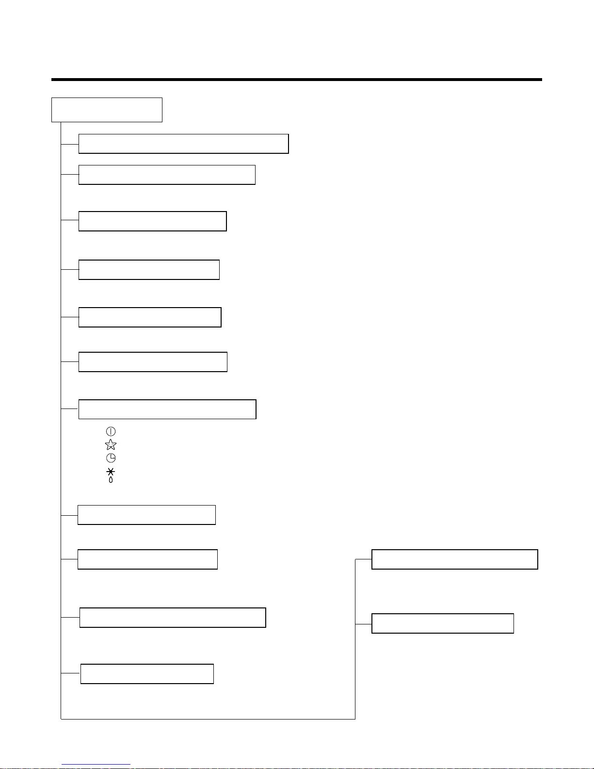
Functions
• Room temperature sensor. (THERMISTOR)
• Maintains the room temperature in accordance with the Setting Temp.
• Indoor fan is delayed for 5 sec at the starting.
• Restarting is inhibited for approx. 3 minutes.
• High, Med, Low
--- Lights up in operation
--- Lights up in Sleep Mode
--- Lights up in Timer Mode
--- Lights up in Deice Mode (for Heating Model)
OUTDOOR --- Lights up in compressor operation (for Cooling Model)
• Intermittent operation of fan at low speed.
• The fan is switched to low(Cooling), med(Heating) speed.
• The unit will be stopped after 1, 2, 3, 4, 5, 6, 7 hours.
• The fan is switched to intermittent or irregular operation
•
The fan speed is automatically switched from high to low speed.
• The louver can be set at the desired position or swing
up and down automatically.
Indoor Unit
Operation ON/OFF by Remote controller
Sensing the Room Temperature
Room temperature control
Starting Current Control
Time Delay Safety Control
Indoor Fan Speed Control
Operation indication Lamps (LED)
Soft Dry Operation Mode
• Both the indoor and outdoor fan
stops during deicing.
• The indoor fan stops until the
evaporator piping temperature will be
reached at 28°C.
Sleep Mode Auto Control
Natural Air Control by CHAOS Logic
Airflow Direction Control
-3-
Deice (defrost) control (Heating)
Hot-start Control (Heating)
-4-
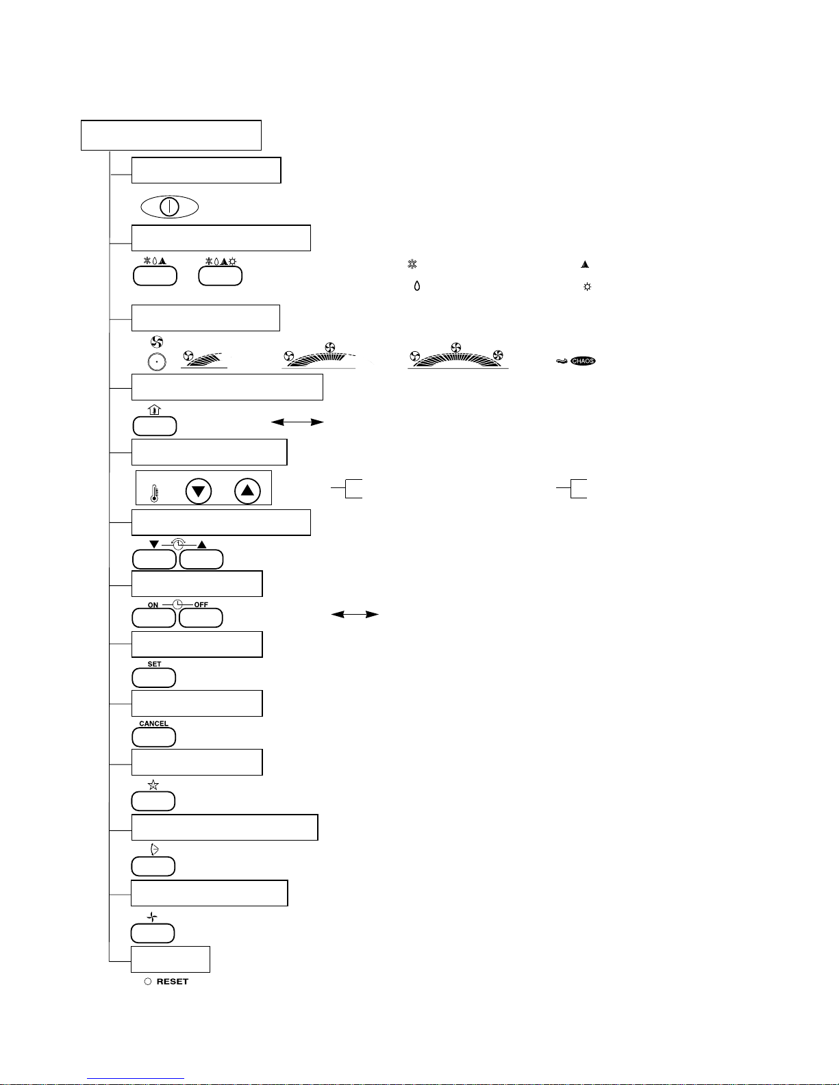
TEMPERATURETEMPERATURE
LOWLOW
HIGHHIGH
Cooling Operation Mode ( ) Auto Operation Mode ( )
Soft Dry Operation Mode ( ) Heating Operation Mode ( )
(Heating model only) (Cooling model only)
Remote Controller
Operation ON/OFF
(Low)
(Med)
(High)
(CHAOS)
: High: 39°C LOW : 11°C
Down to 18°C
Up to 30°C,
Cooling
: OFF, ON, OFF ON
: Cancel Sleep Mode, Timer ON or Timer OFF
: 1, 2, 3, 4, 5, 6, 7, Off Timer
: Fan Operates without cooling or heating.
Operation Mode Selection
Fan Speed Selection
Room, Temperature Display
Temperature Setting
Setting the Time or timer
Timer Selection
Timer Setting
Timer Cancel
Sleep Operation
Airflow Direction Control
Air Circulation Mode
Reset
Down to 16°C
Up to 30°C,
Heating
-5-
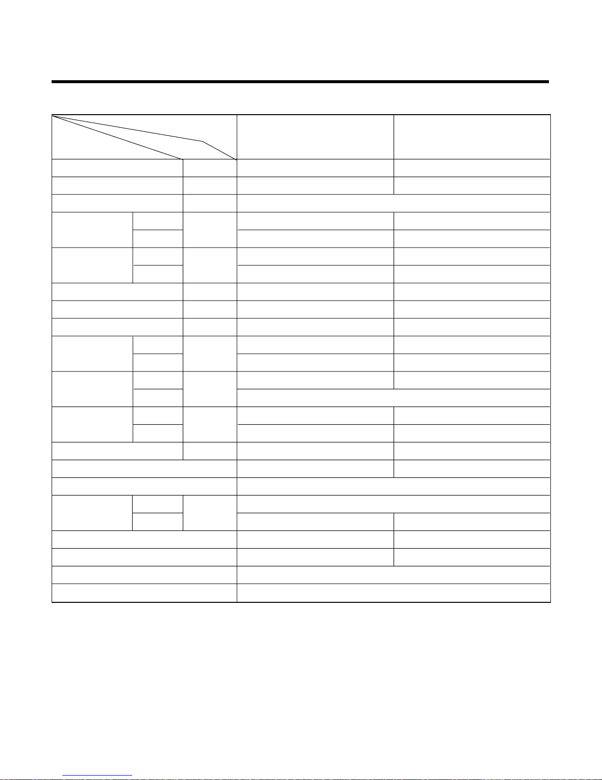
Product Specifications (Cooling Only)
Model Name
Item Unit
Cooling Capacity Btu/h 8,700 12,000
Moisture Removal l/h 1.2 1.2
Power Source Ø, V, Hz 1Ø, 220-240V, 50Hz
Indoor 5.2 8.6
Outdoor 25 25
Indoor 35 36
Outdoor 48 49
Input W 890 1,070
Running Current A 3.8 4.6
E.E.R. Btu/hw 9.77 11.2
Indoor 5.7 15
Outdoor 14.5 25
Indoor 804×245×153 900×280×178
Outdoor 684×624×270
Indoor 7 9
Outdoor 25 28
Refrigerant (R-22) g 600 860
Airflow Direction Control (Up & Down)
Remocon Type L.C.D Wireless
Liquid
inch(mm)
1/4" (6.35)
Gas 3/8" (9.52) 1/2"(12.7)
Sleeping Operation
Drain Hose
Connecting Cable 1.0mm
2
Power Cord 1.0mm
2
Air Circulation
Noise Level
m3/min
dB (A)±1
Service Valve
Motor Output
Dimensions
(W×H×D)
Net. Weight
W
mm
kg
9K Btu 12K Btu
Cooling Only Cooling Only
SPEC. AT 240V
-6-
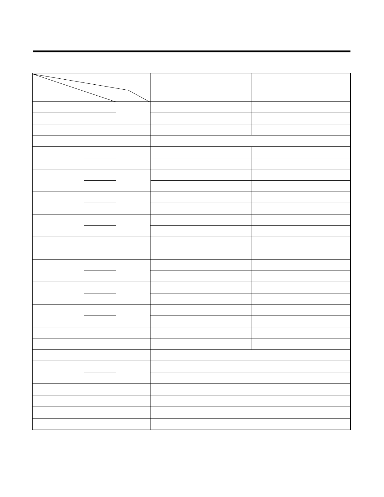
Product Specifications (Cooling & Heating)
Model Name
Item Unit
Cooling Capacity
Btu/h
8,500 12,000
Heating Capacity 9,300 12,500
Moisture Removal l/h 1.2 1.7
Power Source Ø, V, Hz 1Ø, 220-240V, 50Hz
5.4 9.0
24 25
35 37
49 51
Cooling
W
890 1,240
Heating 890 1,090
Running Cooling
A
3.8 5.3
Current Heating 3.8 4.7
E.E.R. Cooling Btu/hw 9.551 9.677
C.O.P Heating 3.062 3.360
10 15
25 25
804 x 245 x 153 900 x 280 x 178
684 x 624 x 270 810 x 555 x 262
79
25 35
Refrigerant (R-22) g 610 860
Airflow Direction Control (Up & Down)
Remocon Type L.C.D Wireless
inch(mm)
1/4" (6.35)
3/8" (9.52) 1/2"(12.7)
Sleeping Operation
Drain Hose
Connecting Cable 1.0mm
2
Power Cord 1.0mm
2
Air Circulation
Noise Level
Input
m3/min
dB (A)±1
Indoor
Outdoor
Indoor
Outdoor
Indoor
Outdoor
Indoor
Outdoor
Indoor
Outdoor
Liquid
Gas
Service Valve
Motor Output
Dimensions
(W×H×D)
Net. Weight
W
mm
kg
9K Btu 12K Btu
Cooling & Heating Cooling & Heating
SPEC. AT 240V
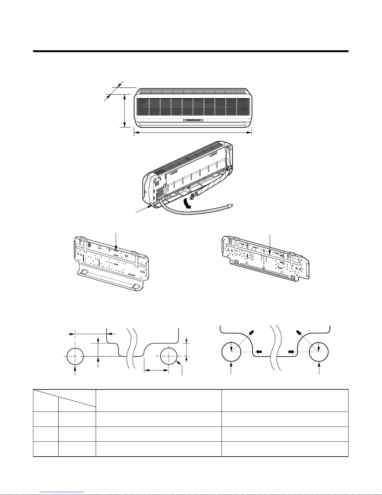
Dimensions
(1) Indoor Unit
-7-
Installation plate
Tubing hole cover
Installation plate
D
H
W
Right rear piping
Left rear piping
ø70mm
ø70mm
50mm
20mm
20mm
80mm
ø70mm
A
A
A
A
Center
Right rear pipingLeft rear piping
Center
ø70mm
MODEL
DIM Unit
W mm 804 900
H mm 245 280
D mm 153 178
9K Btu Series
12K Btu Series
( 9K, 12K )
( 9K )
( 12K )
( 9K )
( 12K )
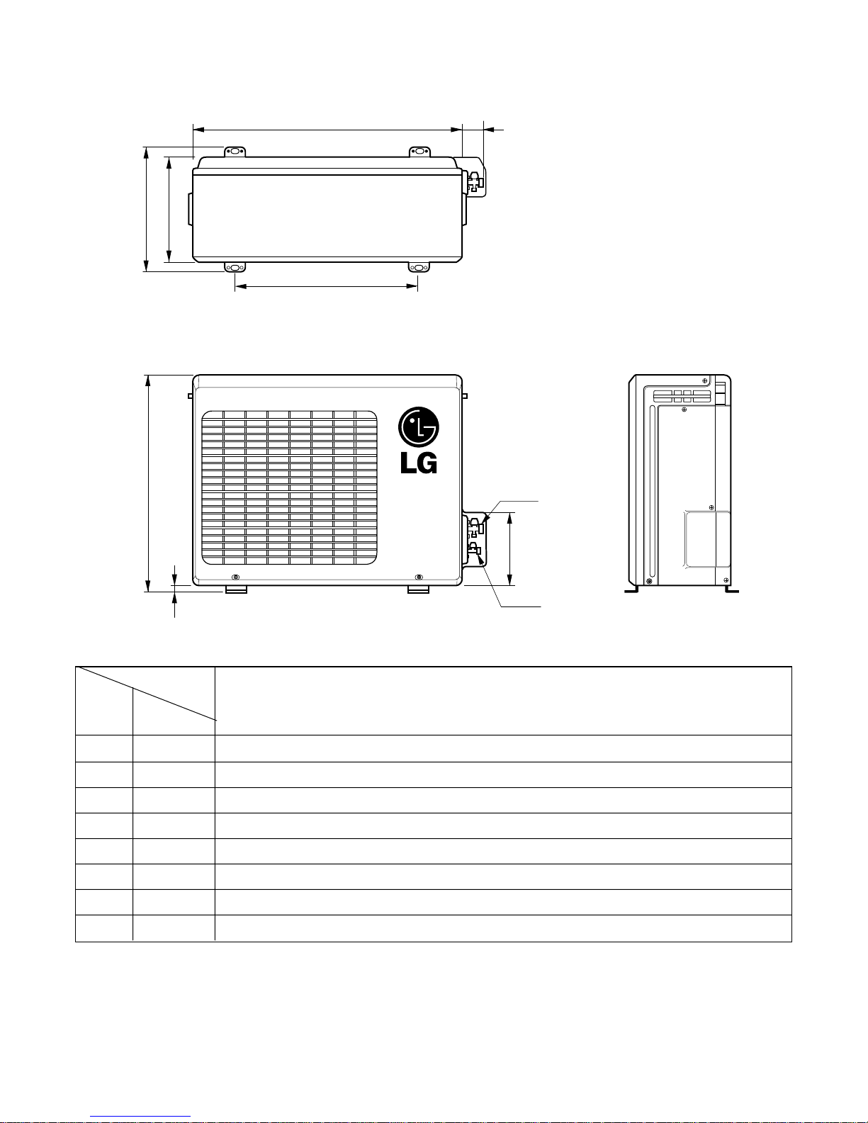
(2) Outdoor Unit ( 9K, 12K)
W
L2
L3
L1
D
H
L4
L5
Gas side
(3-way valve)
Liquid side
(2-way valve)
MODEL
DIM unit
W mm 684
H mm 640
D mm 270
L1 mm 305
L2 mm 62
L3 mm 472
L4 mm 16
L5 mm 193
9K Btu Cooling & Heat Pump
12K Btu Cooling Only
-8-
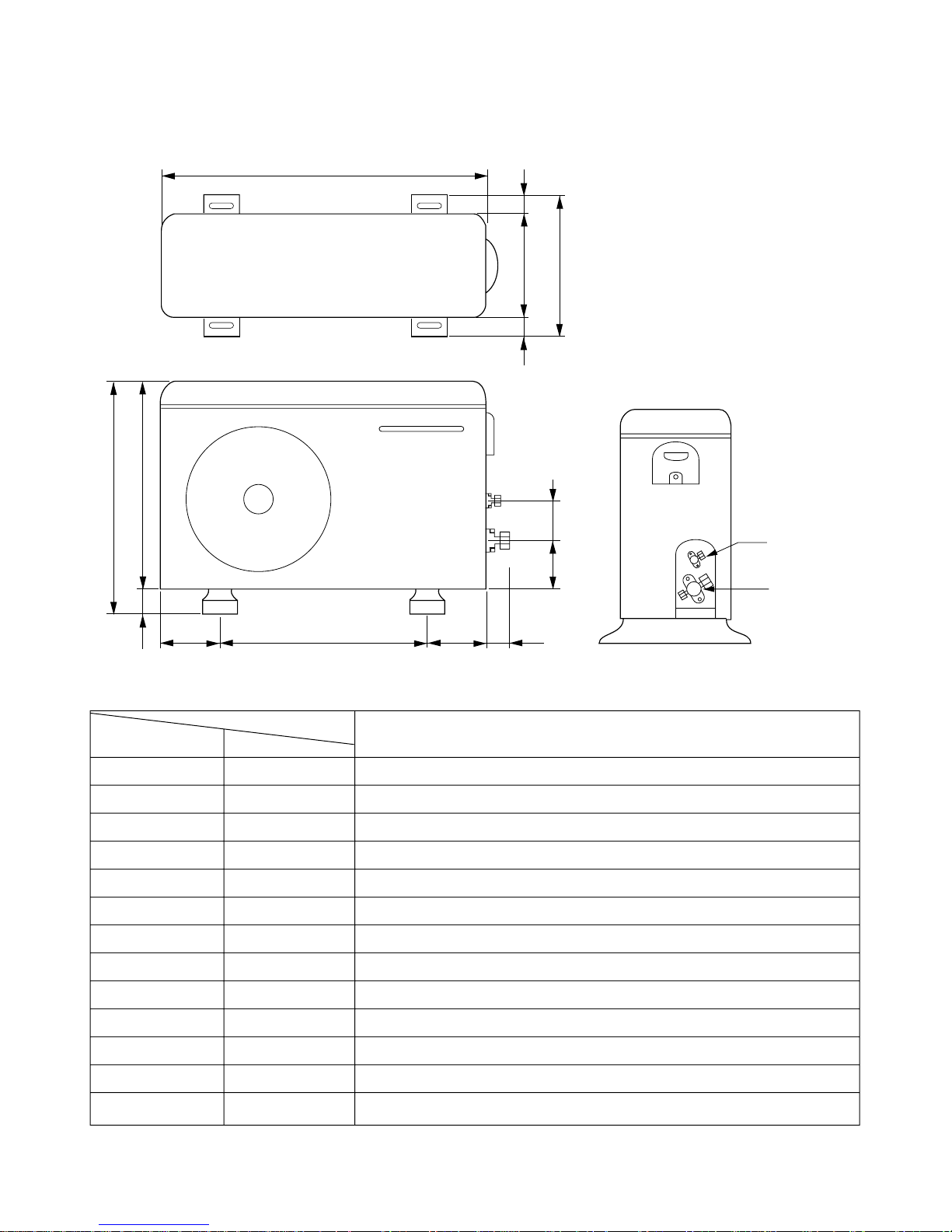
(3) Outdoor Unit(12K Heat Pump)
W
D
L1
L2
H
L3
L4
L5L6 L7 L8
L9
L10
Liquid side
2-way valve
Gas side
3-way valve
-9-
MODEL
12K Btu Heat Pump
DIM unit
W mm 801
H mm 555
D mm 262
L1 mm 339
L2 mm 37
L3 mm 543.6
L4 mm 11.4
L5 mm 591
L6 mm 105
L7 mm 105
L8 mm 72.5
L9 mm 86.4
L10 mm 77
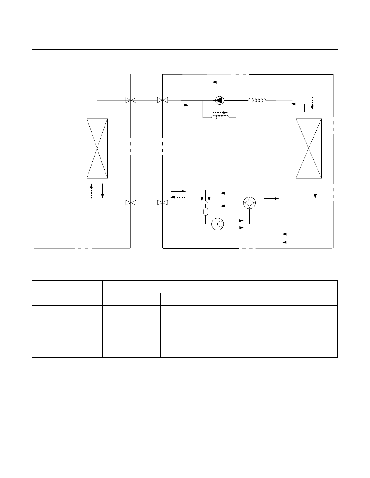
Refrigeration Cycle Diagram
-10-
Pipe size(Diameter:Ø)
MAX. Max
MODEL Piping length Elevation
Gas(inch) Liquid(inch)
(m) (m)
3/8" 1/4" 15 7
INDOOR UNIT OUTDOOR UNIT
HEAT
EXCHANGE
(EVAPORATOR)
HEAT
EXCHANGE
(CONDENSER)
COMPRESSOR
ACCUMU
LATOR
GAS SIDE
3-WAY VALVE
LIQUID SIDE
2-WAY VALVE
CAPILLARY TUBE
CHECK VALVE
(Heating Model only)
COOLING
HEATING
REVERSING
VALVE
(Heating Model Only)
1/2" 1/4" 15 7
9K Btu SERIES
12K Btu SERIES
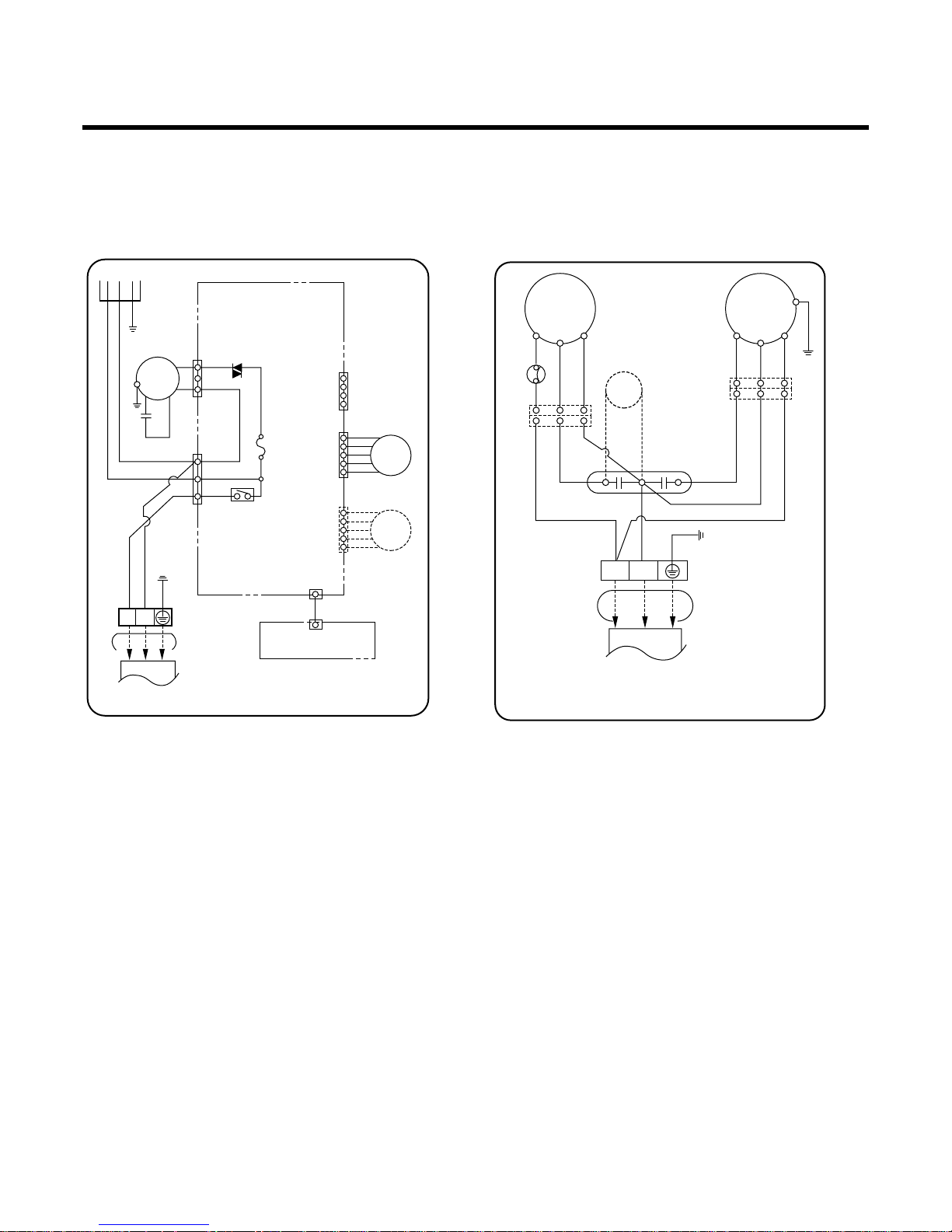
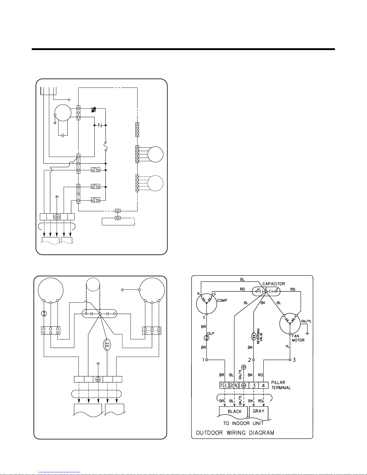
Wiring Diagram
-11-
DISPLAY PCB ASM
INDOOR WRING DIAGRAM
MAIN PCB
ASM
3854AR6093A
CN-DISP
PILLAR
TERMINAL
RY-COMP
CN-POWER
FUSE AC250V/T2A
SSR
CN-FAN
SH-CAPA
MOTOR
CN-UP/DOWN
CN-TH
CN-LE/RI
TO OUTDOOR UNIT
STEP
MOTOR
LE/RI
STEP
MOTOR
UP/DOWN
1(L) 2(N)
GN/YLGN/YL
BLBR
BL
BR
BL
YL
OR
BK
BR
GN/YL
BR
THERMISTOR
POWER
RD
BL
BL
GN/YL
BR
GN/YL
BL
BL BL
BL
YL
RD
BL
YL
RD
GN/YL
RD
BL
BR
BR
BR
HCF
PTC
C
S
R
OLP
1(L) 2(N)
3854AR6093B
FAN
MOTOR
COMP.
CAPACITOR
BR YL
OUTDOOR WIRING DIAGRAM
TERMINAL
BLOCK
TO INDOOR UNIT
SUPPORT
VALVE
1. Indoor Unit 2. Outdoor Unit
(1) 9K, 12K, Btu Cooling Only
-12-
DISPLAY PCB ASM
INDOOR WRING DIAGRAM
MAIN PCB
ASM
3854AR6093C
CN-DISPLAY
PILLAR
TERMINAL
RY-COMP
RY-4WAY
RY-FAN
CN-POWER
FUSE AC250V/T2A
SSR
ZNR
CN-FAN
SH-CAPA
MOTOR
CN-UP/DOWN
CN-TH
CN-LE/RI
TO OUTDOOR UNIT
STEP
MOTOR
STEP
MOTOR
1(L) 2(N)
34
GN/YL
GN/YL
BLBR
BL
BR
RD
BK
RD
BK
BL
YL
OR
BK
BR
GN/YL
BR
THERMISTOR
POWER
BL BK
BK
BL
YL
YL
BR
RDBL
BR
RD
GN/YL
GN/YL
BL BK
RD
BR
GN/YL
BL BL
PTC
3854AR6093D
FAN
MOTOR
RD
BL
BR
C
S
R
COMP.
REVERSING
VALVE
OUTDOOR WIRING DIAGRAM
TERMINAL
BLOCK
TO INDOOR UNIT
OLP
H
CF
CAPACITOR
1(L) 2(N) 3 4
1. Indoor Unit
(2) 9K, 12K Btu Cooling & Heating
2-1. Outdoor Unit (9K)
2-2. Outdoor Unit (12K)
3854AR2262E
Operation Details
1. Time Delay Safety Control
• 3min. ;The compressor operation is delayed for 3 minutes to balance the pressure of cycle.
(Protection of compressor)
• 5sec. ;
The indoor fan is delayed for 5 seconds, when operating initially, to prevent noises occurred by the vertical
louver and wind.
• 30sec
.;
The 4-way valve is ceased for 30sec. to prevent the refrigerant-gas abnormal noise when the Heating
operation is OFF or switched to the other operation mode.
2. Airflow Direction Control
• This function is to swing the vertical louver up and down automatically and to set it at a fixed position.
• The procedure is as the following.
1st ; Press the ON/OFF Button to operate the unit.
2nd ; Press the Airflow Direction Control Button to swing the vertical louver up and down automatically.
3nd ; Repress the Airflow Direction Control Button to set the vertical louver at a fixed position.
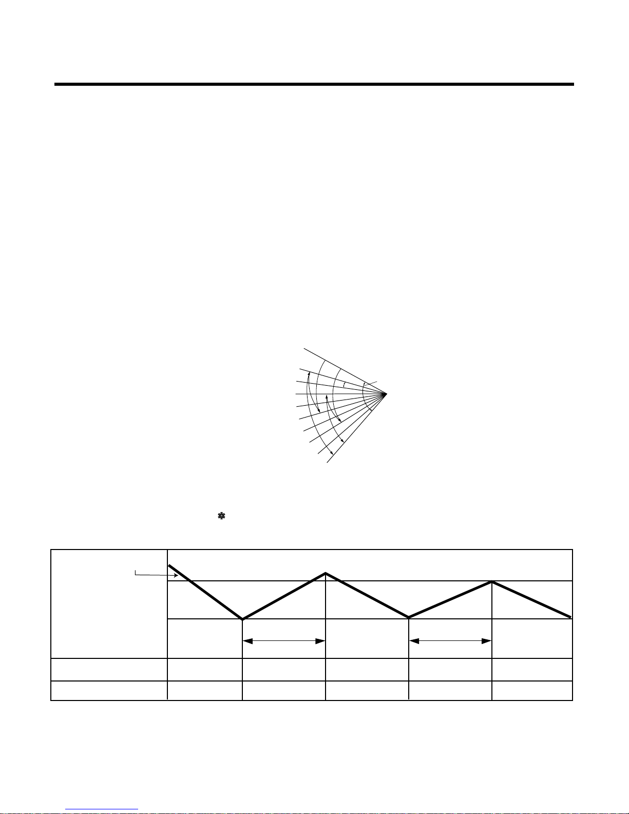
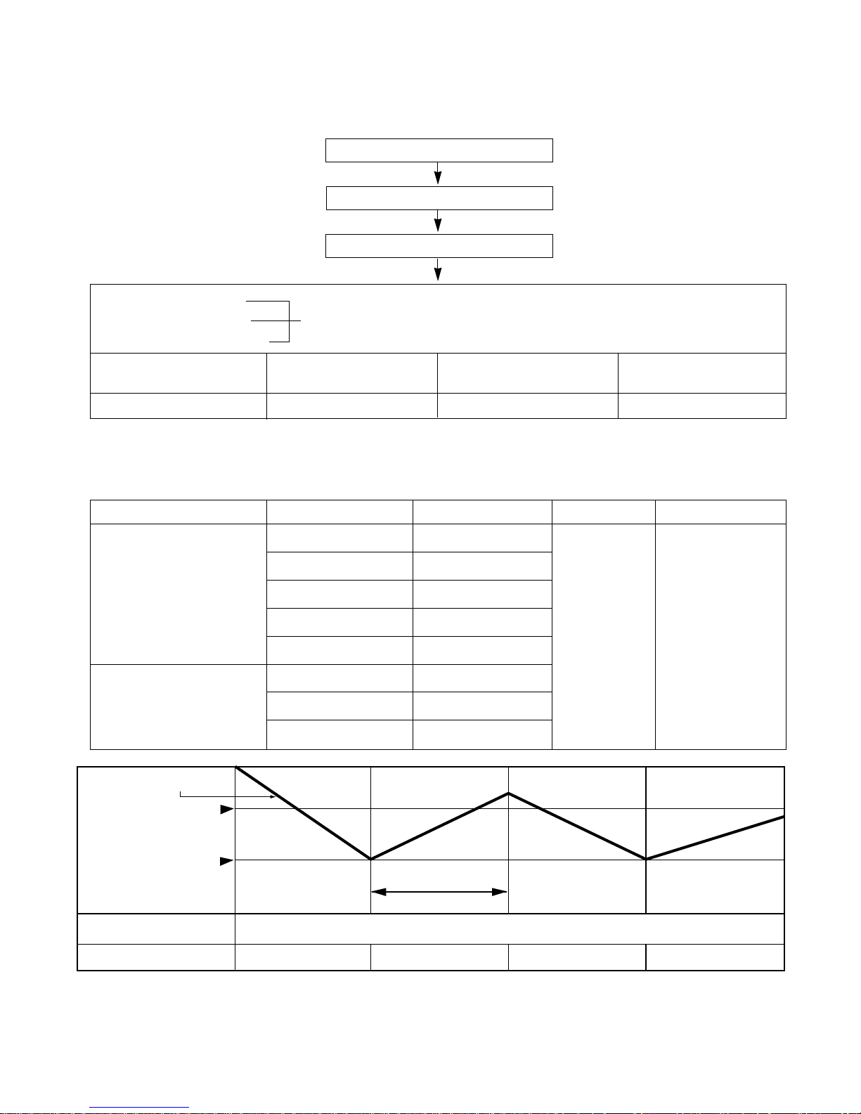
3. Cooling Mode Operation
• When selecting the Cooling( ) Mode Operation, the unit will operate according to the setting by the
remote controller and the operation diagram is shown below.
-13-
Setting point:
(Cooling)
CLOSED
OPEN
Cooling
Heating
140°
8°
8
7
6
5
4
3
2
1
Setting point:
(Heating)
INTAKE AIR TEMP.
SETTING TEMP. +0.5°C
(Compressor ON)
SETTING TEMP. -0.5°C
(Compressor OFF)
More than
3 minutes
More than
3 minutes
INDOOR FAN SPEED
COMPRESSOR
Selecting
fan speed
Selecting
fan speed
Selecting
fan speed
Low
ON OFF ON ONOFF
Low
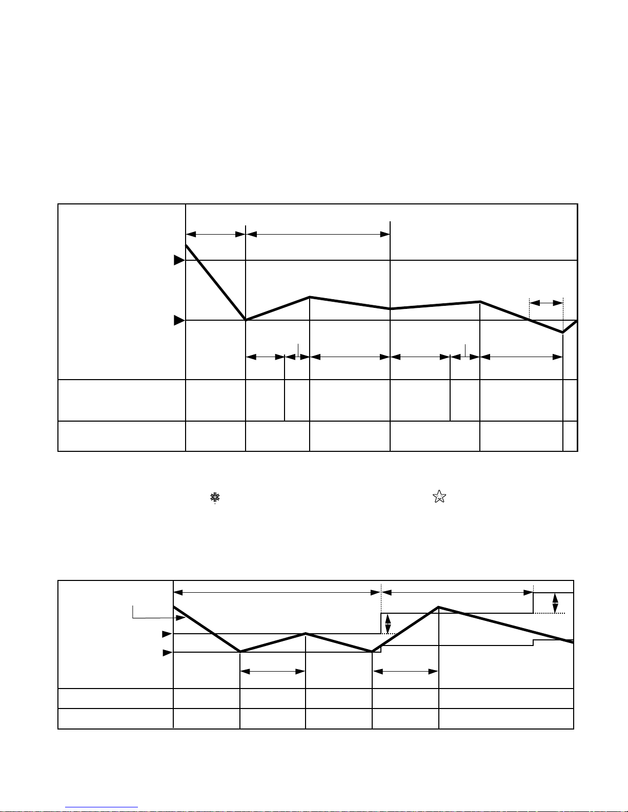
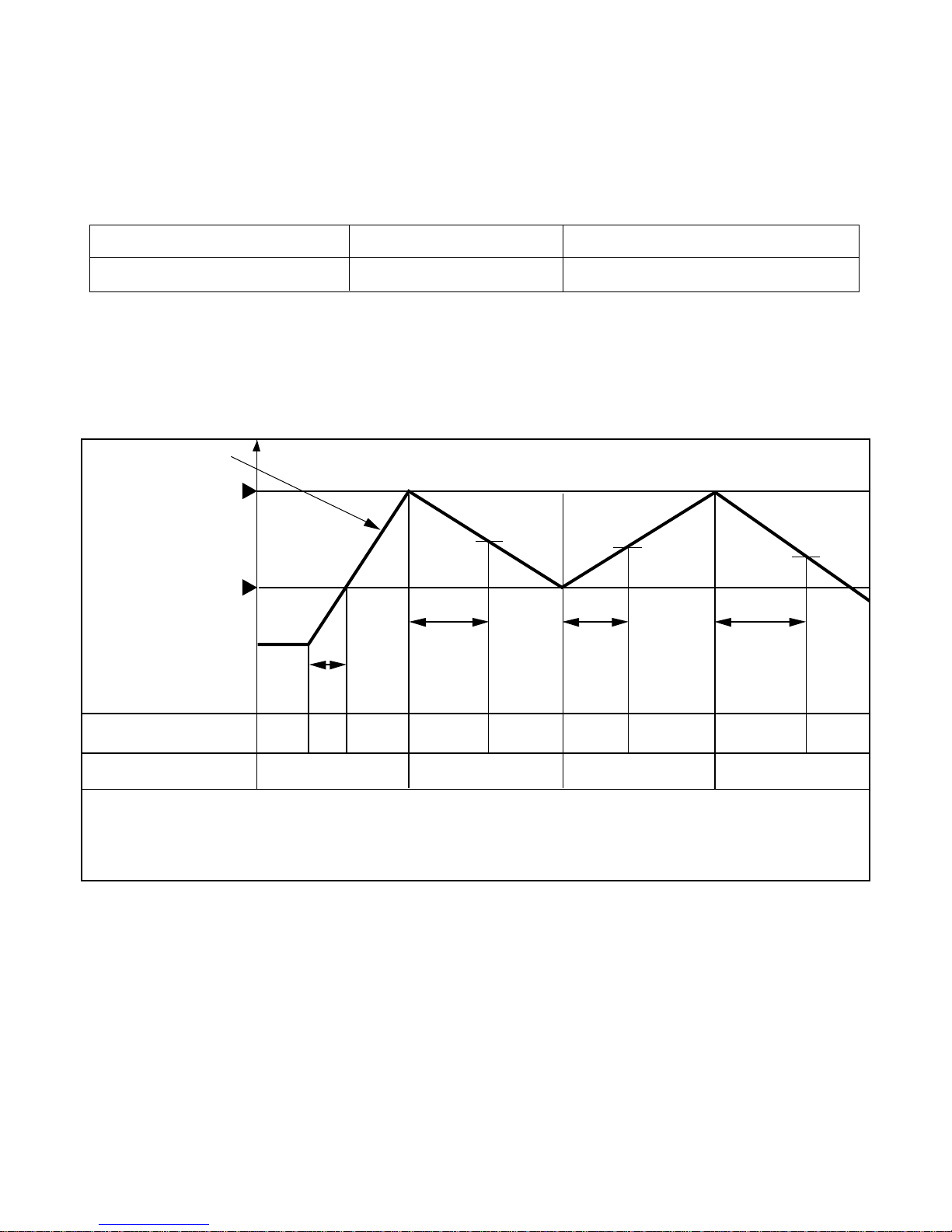
4. Soft Dry Operation Mode
• During Soft Dry Operation, the compressor ON temperature is the setting temperature plus 0.5°C, the compressor OFF temperature is the setting temperature minus 0.5°C.
• When the room temperature rises over the compressor ON temperature, the operation mode is switched to
the Cooling operation.
• When the room temperature falls the compressor OFF temperature, the operation mode is switched to the
Soft Dry Operation.
• The operation diagram is shown below.
-14-
INDOOR FAN
Selecting
fan speed
LOW
LOW LOW
ON ON ONOFF OFF
OFF LOWOFF
Operation
Cooling
Dry Operation
COMPRESSOR
SETTING TEMP.+0.5°C
(COMP. ON)
ROOM TEMP.
SETTING TEMP.
(COMP. OFF)
3.2 minutes
10 minutes
40 seconds 40 seconds
3.2 minutes
maximum
10 minutes
maximum
3 minutes
5. Cooling Mode with Sleep Mode Auto Control
•When selecting the Cooling( ) combined with the Sleep Mode Auto Control( ), the operation diagram is
as following.
•The setting temperature will be automatically raised by 1°C 30 minutes later and by 2°C 1 hour later.
•The operation will be stopped after 1, 2, 3, 4, 5, 6, 7 hours.
INTAKE AIR TEMP.
INDOOR FAN SPEED Low Low Low Low
ON OFF ON
Low
More than
3 minutes
More than
3 minutes
30 minutes 30 minutes
ONOFFCOMPRESSOR
SETTING TEMP.+0.5°C
(Compressor ON)
SETTING TEMP.-0.5°C
(Compressor OFF)
1°C
1°C
-15-
6. Auto Operation
• The operation procedure is as following.
☛ If initial mode is decided, that mode is continued despite of the room temperature changing.
• Auto Operation for Cooling
Press Start/Stop Button
Select Auto Operation Mode
Check the Room temperature
Operation mode
Indoor fan speed are automatically decided by Fuzzy rule.
Setting temperature
Intake-air
temperature
Operation Mode
Over below
21°C24
°
C
Soft Dry
below 21°C
Heating
Over 24°C
Cooling
~
Intake-Air temp.
INDOOR FAN SPEED
COMPRESSOR ON OFF
Fuzzy Speed
ON OFF
Setting Temp. +0.5°C
(Compressor OFF)
Setting Temp. -0.5°C
(Compressor ON)
More than
3 minutes
Intake-air Temperature Setting Temperature
Over 26°C25°C
Over 24°C~below 26°C Intake air -1°C
Over 22°C~below 24°C Intake air -0.5°C
Over 18°C~below 22°C Intake air temperature
below 18°C18°C
Over 18°C~below 30°C Fuzzy control
below 18°C18°C Fuzzy control
over 30°C30°C Fuzzy control
Operation Condition
When Auto Operation
initial start
Controlled by
Fuzzy logic
1/f rhythm
Fan Speed Air DirectionControl
When Switch to Auto
Operation
-16-
■ Auto Operation for Soft Dry
The Setting temperature will be same that of auto operation for Cooling.
- Compressor ON temperature; Setting temperature +0.5°C
- Compressor OFF temperature; Setting temperature -0.5°C
■ Auto Operation for Heating
Intake Air temp. below 20°C Over 20°C~below 21°C
Setting temp. 20°C Intake air temperature +0.5°C
7. Heating Mode Operation
The unit will operate according to the setting by the remote controller and the operation diagram is shown as following.
Intake Air temp.
INDOOR FAN SPEED OFF
Hot
Start
Selecting
fan speed
Selecting
fan speed
LOW
LOW
A
minimum
10sec.
1 min.
minimum
10sec.
minimum
10sec.
A
B
LOWOFF LOW OFF
COMPRESSOR ON OFF ON OFF
Setting temp. +3°C
(Compressor OFF)
• A point; The indoor pipe temperature to be 35°C.
The indoor fan operates minimum 10sec. even if falls lower than 35°C.
• B point; The indoor fan operates minimum 10sec.
Setting temp.
(Compressor ON)
-17-
8. Hot-Start Control
• The indoor fan stops until the evaporator piping temperature will be reached at 28°C.
• The operation diagram is as following.
28°C
PIPE TEMP.
INDOOR
FAN SPEED
OFF LOW
SELECTING
FAN SPEED
COMPRESSOR
HOT-START BY TEMPERATURE
ON
60 sec.
-18-
T1
TE1
TE2
T2
COMPRESSOR
TEMP °C
Pipe Temp.
Intake Air
Temp.
4-WAY VALVE
OUTDOOR FAN
INDOOR FAN
DEICE LED
ON
Heating
25 mins
60 minutes
25 mins
Deicing
Hot
Start Heating
ON(Heating Operation)
ON
ON
OFF
ON
ON
ON
ON
OFF
ON
OFF
OFF
ON
ON
ON
OFF
ON
T1
T2
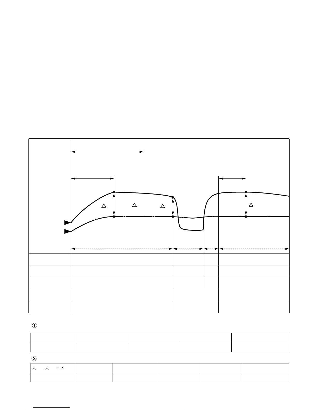
9. Deice Control
• Deicing operation is controlled by timer and sensing the indoor pipe temperature.
• Deicing operation checks the indoor pipe temperature and Intake-air temperature at 25 minutes and 60 minutes
on starting of heating operation, and discriminates by temperature difference.
• When the heating operation passed 25 minutes, the temperature (△T1=TE1–TR1) is checked and memorized
with checking the indoor pipe temperture (TE1) and the indoor Intake-air temperature (TR1).
• When the heating operation passed 60 minutes, deicing operation checks the indoor pipe temperature (TE2)
and the indoor Intake-air temperature (TR2), and checks indoor pipe temperature(TE2), the temperature
difference (△T2=TE2–TR2) and the temperature difference △Td(=△T1–△T2) of △T1, △T2.
If temperature of indoor pipe is below 32°C Deicing function operates at the priority I condition.
If temperature of indoor pipe is over 32°C Deicing function operates at the priority II condition.
If the temperature difference (△Td) become more than the option temperature, deicing operation starts.
• At that time, deicing operation time is decided.
• The deicing operation time starts after deicing operation started.
• If deicing operation start, above heating operation time is reset, so if deicing operation is finished, the heating
operation time is recounted.
• The deicinig time and the operation diagram are as following.
T1- T2 Td Over 6°C 5~6°C 4~5°C 3~4°C below 2.0°C
Deicing Time 10mins 9mins 8mins 7mins Heating Operation
TE2 Below 30°C 30~31°C 31~32°C Over 32°C
Deicing Time 12mins 11mins 10mins Heating Operation
(DEICING DIAGRAM)
Priority I
Priority II
-19-
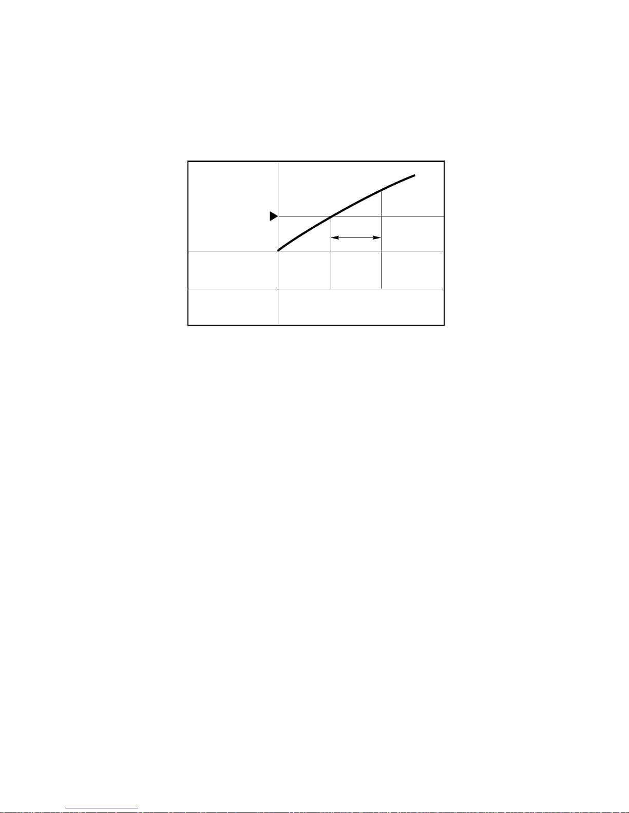
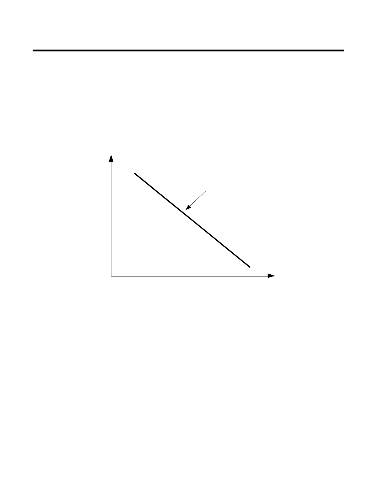
10. Natural Wind by CHAOS Logic
There are common rules in the irregular changes amid the breeze of highlands and valleys, the sound of
streams, the songs of birds in the forest and brain waves of relaxation.
Mmm... the breath-taking and touchy feeling of wind from the deep mountains and dark valleys.
Through analysis in its chaos simulator, Goldstar has successfully created such a feeling of freshness and
serenity by analyzing the frequency of natural wind.
Generally natural wind has the following character (frequency-Magnitude), for example dark valley, sea, mountain wind.
So as to make a similar Natural wind function, Indoor fan speed is shifted to high from low or reversely according
to the CHAOS logic.
Magnitude
Natural wind function
Frequency(Hz)
-20-
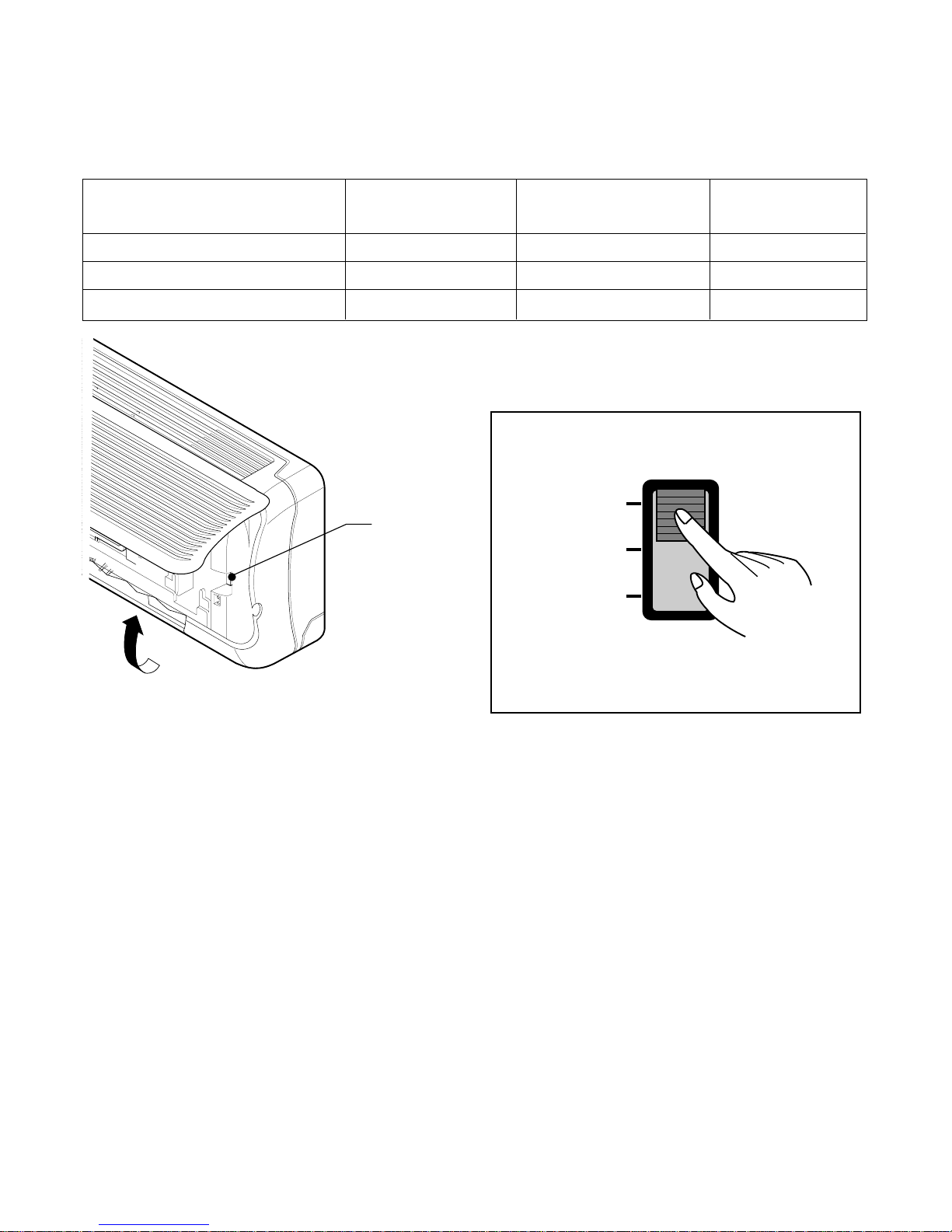
11. Forced Operation
• If you lose wireless remote controller, you can operate the unit with forced operation switch.
• The standard conditions are as following.
12. AUTO RESTART
In case the power comes on again after a power failure, Auto Restarting Operation is the function to operate
procedures automatically to the previous operating conditions.
In case the air conditioner does not receive any signal from the remote control, it will turn off automatically after
7 hours.
If you want to use this operation, Open the front panel upward and move the slide switch to the Auto Restart
position.
If you do not want to use this operation, move the Slide Switch to the Remote control position.
Slide Switch
FORCED
OPERATION
AUTO
RESTART
REMOTE
CONTROL
• When you are out for a while, move the
Slide switch to the REMOTE CONTROL.
Slide Switch
Open the front
panel upward
Room Temp ≥ 24°C24°C > Room Temp ≥21°C Room Temp<21°C
Cooling Soft Dry Heating
High Low High
22°C23°C24°C
Operation Mode
FAN Speed
Setting Temp
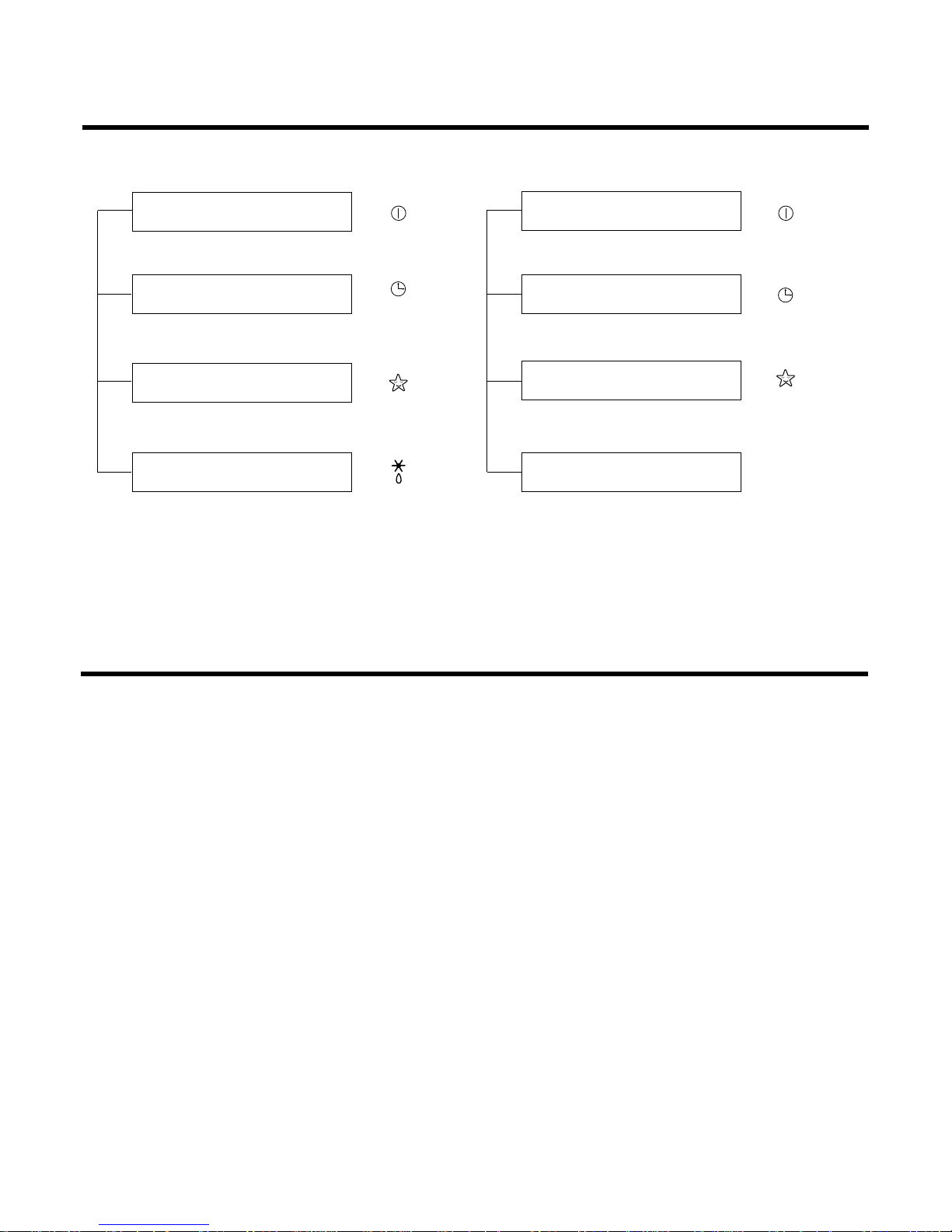
Display Function
1. Heating Model 2. Cooling Model
• Cooling, Soft Dry, Fan, Heating • Cooling, Soft Dry, Fan
• Timer Mode • Timer Mode
• Sleep Mode • Sleep Mode
• Hot-start, Deice
Self-diagnosis Function
■ Thermistor Cut Off or Short
Cut Off/Short : Blinks on and off the operation mode LED. (0.5 sec ON/3 sec OFF)
■ Protection of the evaporator pipe from frosting
If the temperature of the indoor pipe is below 0°C after 7 minutes from starting the compressor, the compressor
and outdoor fan is stopped, and then after 3 minutes delay of operating of the compressor, when the temperature of the indoor pipe is over 7°C, the compressor and the outdoor fan is reoperated.
Operation Indicator
Sleep Timer Indicator
Timer Indicator
Deicer Indicator
-21-
Operation Indicator
Sleep Timer Indicator
Timer Indicator
Compressor on Indicator
OUT
DOOR
 Loading...