

Page 1
REFRIGERATOR
SERVICEMANUAL
CAUTION
PLEASE READCAREFULLY THE SAFETY PRECAUTIONS OF THIS MANUAL
BEFORECHECKING OR OPERATING THE REFRIGERATOR.
MODEL : LSC27926**
Page 2

CONTENTS
WARNINGS AND PRECAUTIONS FOR SAFETY ................................................................................................................ 3
SPECIFICATIONS................................................................................................................................................................... 4
PARTS IDENTIFICATION....................................................................................................................................................... 5
HOW TO INSTALL THE REFRIGERATOR .......................................................................................................................... 6
HOW TO ADJUST DOOR HEIGHT.................................................................................................................................... 6
FILTER................................................................................................................................................................................ 7
HOW TO CONTROL THE ICEMAKER WATER SUPPLY.................................................................................................. 8
MICOM FUNCTION .............................................................................................................................................................. 10
EXPLANATION OF MICOM CIRCUIT.................................................................................................................................. 23
EXPLANATION OF PWB CIRCUIT.....................................................................................................................................23
PWB PARTS DIAGRAM AND LIST.....................................................................................................................................40
PWB CIRCUIT DIAGRAM...................................................................................................................................................43
ICE MAKER AND DISPENSER WORKING PRINCIPLES AND REPAIR ...........................................................................46
WORKING PRINCIPLES.................................................................................................................................................... 46
FUNCTION OF ICE MAKER .............................................................................................................................................. 47
ICE MAKER TROUBLESHOOTING................................................................................................................................... 48
ICE MAKER CIRCUIT .........................................................................................................................................................49
CIRCUIT................................................................................................................................................................................ 53
TROUBLE DIAGNOSIS........................................................................................................................................................ 54
TROUBLESHOOTING ....................................................................................................................................................... 54
FAULTS .............................................................................................................................................................................. 64
COOLING CYCLE HEAVY REPAIR ................................................................................................................................. 81
HOW TO DEAL WITH CLAIMS ........................................................................................................................................ 88
HOW TO DISASSEMBLE AND ASSEMBLE..................................................................................................................... 93
DOOR............................................................................................................................................................................... 93
HANDLE........................................................................................................................................................................... 94
FAN SHROUD GRILLE .................................................................................................................................................... 95
ICEMAKER ASSEMBLY................................................................................................................................................... 95
DISPENSER..................................................................................................................................................................... 96
EXPLODED VIEW &
REPLACEMENT PARTS LIST ........................................................................................................................................... 98
- 2 -
Page 3

WARNINGS AND PRECAUTIONS FOR SAFETY
Please observe the following safety precautions to use the
refrigerator safely and correctly and to prevent accident or
injury when servicing.
1. Be careful of an electric shock. Disconnect power cord
from wall outlet and wait for more than three minutes
before replacing PWB parts. Shut o the power
whenever replacing and repairing electric components.
2. When connecting power cord, please wait for more than
ve minutes after power cord was disconnected from the
wall outlet.
3. Please check if the power plug is pressed by the
refrigerator against the wall. If the power plug was
damaged, it could cause re or electric shock.
4. If the wall outlet is overloaded, it may cause a re.
Please use a dedicated circuit for the refrigerator.
5. Please make sure the outlet is properly grounded.
Particularly in a wet or damp area.
6. Use standard electrical components.
7. Make sure hooks are correctly engaged.
Remove dust and foreign materials from the housing
and connecting parts.
8. Do not fray, damage, run over, kink, bend, pull out, or
twist the power cord.
9. Please check for evidence of moisture intrusion in the
electrical components. Replace the parts or mask with
insulation tape if moisture intrusion was conrmed.
10. Do not touch the icemaker with hands or tools to
conrm the operation of geared motor.
11. Do not suggest that customers repair their refrigerator
themselves. This work requires special tools and
knowledge. Non-professionals could cause re, injury,
or damage to the product.
12. Do not store ammable materials such as ether,
benzene, alcohol, chemicals, gas, or medicine in the
refrigerator.
13. Do not put anything on top of the refrigerator,
especially something containing water, like a vase.
14. Do not put glass bottles with full of water into the
freezer. The contents will freeze and break the glass
bottles.
15. When you scrap or discard the refrigerator, remove the
doors and dispose of it where children are not likely to
play in or around it.
- 3 -
Page 4
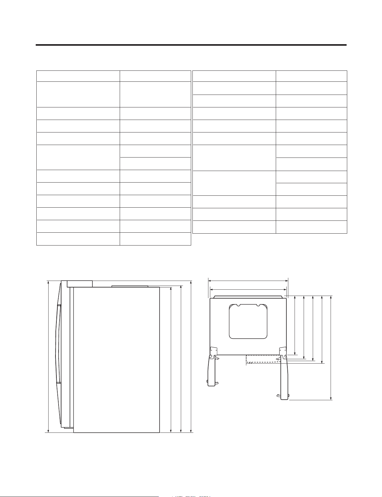
SPECIFICATIONS
ITEMS SPECIFICATIONS
DIMENSIONS 912X829X1771 mm
WXD
X
H
(35.9x32.6x69.7in)
286.6
).sbl(gk301THGIEWTEN
COOLING SYSTE Fan Cooling
TEMPERATURE CONTROL
DEFROSTING SYSTEM
Micom Control
Full Automatic
Heater Defrost
enatneP-olcyCNOITALUSNI
COMPRESSOR
EVAPORATOR
CONDENSER
REFRIGERANT
LUBRICATING OIL
PTC Starting Type
Fin Tube Type
Wire Condenser
R134a(185g)(6.5oz)
FREOL @ 10G(310cc)
ITEMS SPECIFICATIONS
CAPILLA R Y TUBE ID Ø0.8 5
FIRST DEFROST
DEFROST CYCLE
DEFROSTING DEVICE
ANTI-SWEAT HEATER
4-5 Hours
13-15 Hours
Heater, Sheath
Dispenser Duct Door Heater
Dispenser Heater
ANTI-FREEZING HEATER
Water Tank Heater
Damper Heater
FREEZER LAMP
REFRIGERATOR LAMP
DISPENSER LAMP
40W (1 EA)
40W (4 EA)
15W (1 EA)
7-HXEVEISRALUCELOMREIRD
in.)
16
/
1
1
1771 mm (69
in.)
in.)
2
/
1
1741.5 mm (68
in.)
4
/
16
3
/
1
1
1771 mm (69
1746.5 mm (68
1004 mm (391/2 in.)
912 mm (35.9in.)
1
weiVpoTweiVtnorF
in.)
in.)
in.)
2
8
8
/
/
/
5
5
5
829 mm (32
724 mm (28
779 mm (30
in.)
in.)
8
/
16
5
/
897 mm (35
1261 mm (49
- 4 -
Page 5
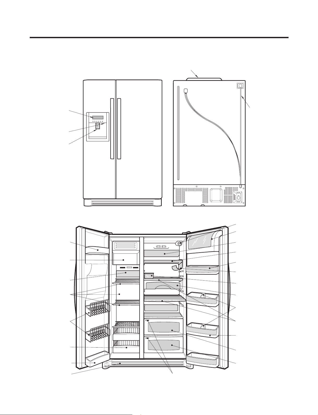
PARTS IDENTIFICATION
Frame Display
Dispenser Lamp
Ice & Water
Dispenser Button
PWB Cover
Water Tubes
Freezer
Compartment
Refrigerator
Compartment
Humidity Switch
Lamp
Shelf
Snack Drawer
Vegetable Drawer
Vegetable Drawer
/Meat Drawer
Door Rack
Shelf
Door Rack
Wine Holder
Lamp
Lower Cover
Dairy Product Corner
Door Rack
Drawer
(Wire/Plastic)
Automatic
Icemaker
Door Rack
Shelf
Bottle Guide
Door Rack
Water Filter
Egg Box
- 5 -
Page 6
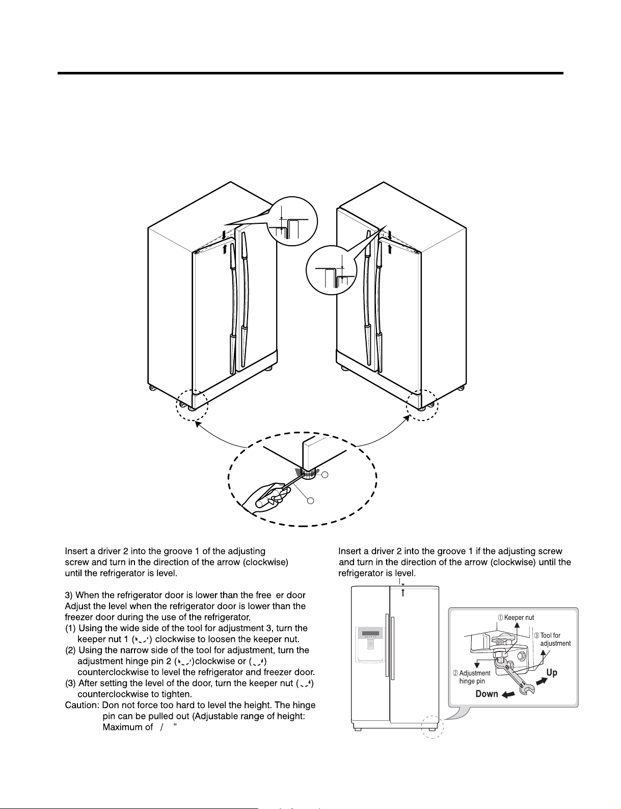
HOW TO INSTALL REFRIGERATOR
1. How to Adjust Door Height of Refrigerator
Make the refrigerator level first. (If the refrigerator is not installed on a flat floor, the height of freezer and refrigerator
door may not be the same.)
1. If the freezer door is lower than the refrigerator
door:
2. If the freezer door is higher than the refrigerator
door:
1 2
Z
-
- 6
Page 7
HOW TO INSTALL REFRIGERATOR
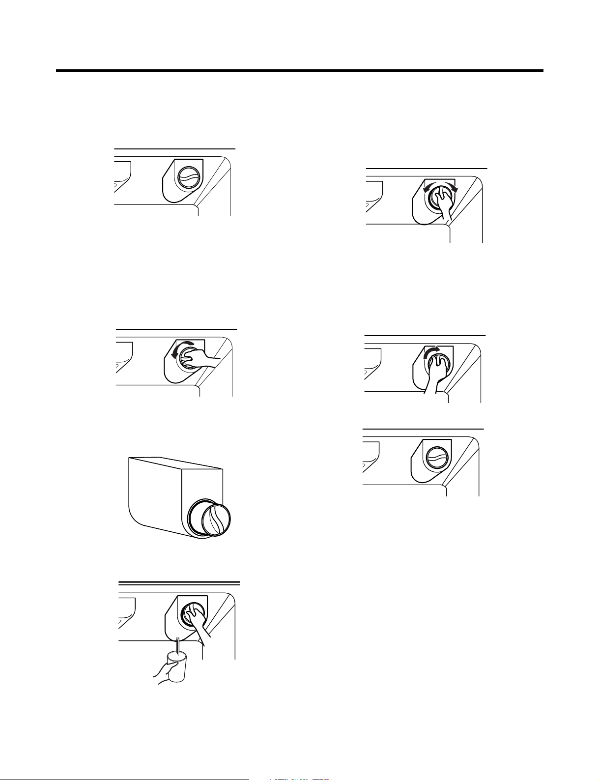
2. Filter
Replace the filter when the indicator light comes on or the
performance of the icemker or water dispenser decreases
noticeably.
After changing the water filter cartridge, reset the water
filter status display and indicator light by pressing and
holding the BUTTON for 3 seconds.(page 18)
1. Remove the old cartridge.
Twist the knob of the cartridge counter clockwise.
2. Replace with a new cartridge.
Take the new cartridge out of its packaging and remove
protective cover from the o-rings.
With cartridge knob in the vertical position, push the new
filter cartridge into the cover until it stops.
If you can’t turn the filter from side to side, it isn’t fully
inserted. Push it in firmly and twist it into place. You will
hear the snap when it clicks into place.
Using the handle, twist the cartridge clockwise about 1/4
turn.
When the cartridge is removed, you will feel it click .
Pull out the cartridge.
NOTE: There will be some water(25cc) in the filter
cartridge. Some spilling may occur. Catch it in a
bowl or towel.
3. Flush the Water System After Replacing Filter Dispense
water through the water dispenser for 3 minutes to
purge the system.
There may be a little air in the line, causing noise or
hissing. Run the water at the dispenser until the hissing
stops to purge the air from the system.
NOTE: - To purchase replacement water filter cartridges,
visit your local appliance dealer or part distributor.
- You can also visit our website :
www.lgappliances.com or call 1-877-714-7481.
- 7 -
Page 8
HOW TO INSTALL REFRIGERATOR
2
1
Test Switch
Confirm the amount
of water
Ice maker
Too much
Too little
Optimum level
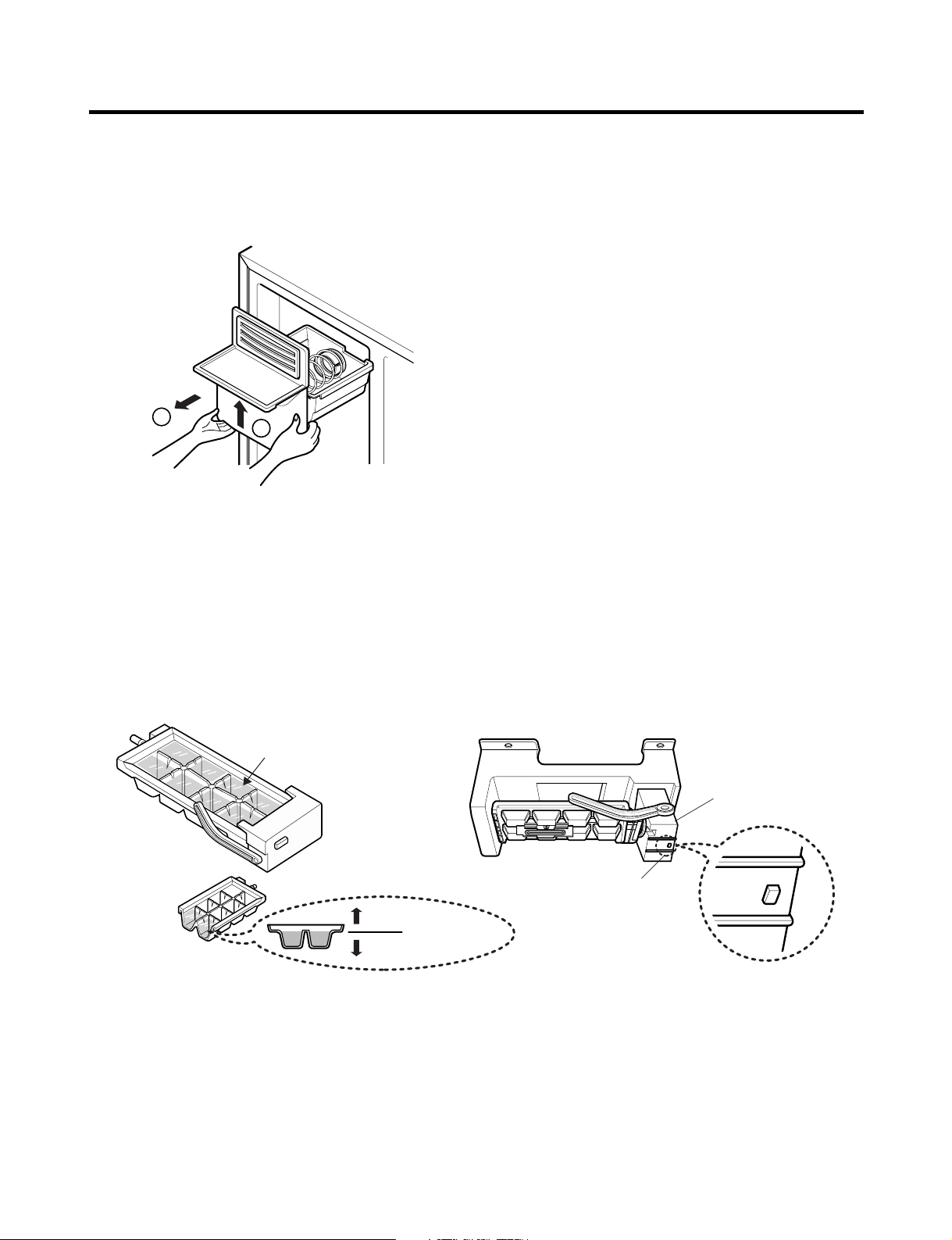
3. How to Control the Amount of Water Supplied to Icemaker.
3-1. Confirm the amount of water supplied to the icemaker.
1. Pull out the ice bin shelf in the upper part of the freezer compartment.
Caution : • Do not put hands or tools into the chute to confirm
the operation of geared motor.
It may damage the refrigerator or hurt your hands.
2. Apply electricity after connecting water pipe.
1) Press test switch under the icemaker for two seconds as shown below.
2) The bell rings(ding~dong) and ice tray rotates and water comes out from the icemaker water tube.
3) The water shall be supplied two or three times into the tray. The amount of water supplied for each time is small.
Put a water container under the ice tray and press test switch.
4) When ice tray rotates, the water in it will spill. Collect the spilt water and throw away into the sink.
5) When ice tray has finished rotation, water comes out from the water tube. Confirm the amounts of water in the ice tray.
(refer to fig. The optimum amount of water is 110cc)
* It is acceptable if the adjusted level of water is a bit smaller than optimum level.
- 8 -
Page 9
HOW TO INSTALL REFRIGERATOR
Conrm the amount
of water
Optimum level
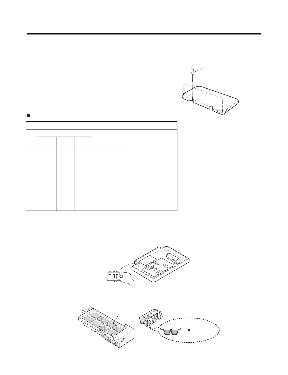
3-2. Control the amount of water supplied to the icemaker.
Caution : • Please unplug the power cord from the wall outlet and wait for more than three minutes before disconnecting
PWB cover as 310V is applied in the control panel.
1. Disconnect PWB cover from the upper part of the refrigerator.
2. Adjust the amount of water supplied by using DIP switch.
Water Supplying Time Control Option
LSC27926**
No
DIP SWITCH SETTING
S1 S2 S3
OFF OFF OFF 6.5 SEC
1
ON OFF OFF 5.5 SEC
2
OFF ON OFF 6 SEC
3
ON ON OFF 7 SEC
4
OFF OFF ON 7.5 SEC
5
ON OFF ON 8 SEC
6
OFF ON ON 9 SEC
7
ON ON ON 10 SEC
8
WATER
SUPPLY TIME
* The quantity of water
supplied depends on DIP
switch setting conditions
and water pressure as it
is a direct tap water
connection type. (the
water supplied is
generally 80 cc to 120 cc)
* DIP switch is on the main
PWB.
(+) Driver
REMARKS
1) The water supplying time is set at ve seconds when the refrigerator is delivered.
2) The amount of water supplied depends on the setting time and water pressure (city water pressure).
3) If ice cube is too small, increase the water supplying time. This happens when too small water is supplied into the ice tray .
4) If ice cube sticks together, decrease the water supplying time. This happens when too much water is supplied into the ice tray.
Caution : When adjusting the amount of water supplied, adjust step by step. Otherwise the water may spill over.
Switch ON
Switch OFF
ON
1
2 3
3. When adjustment of control switch for the amount of water supplied is complete, check the level of water in the ice tray.
- 9 -
Page 10
MICOM FUNCTION
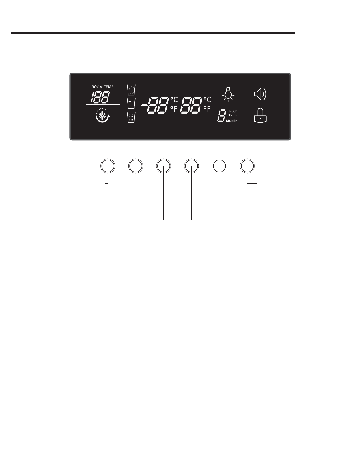
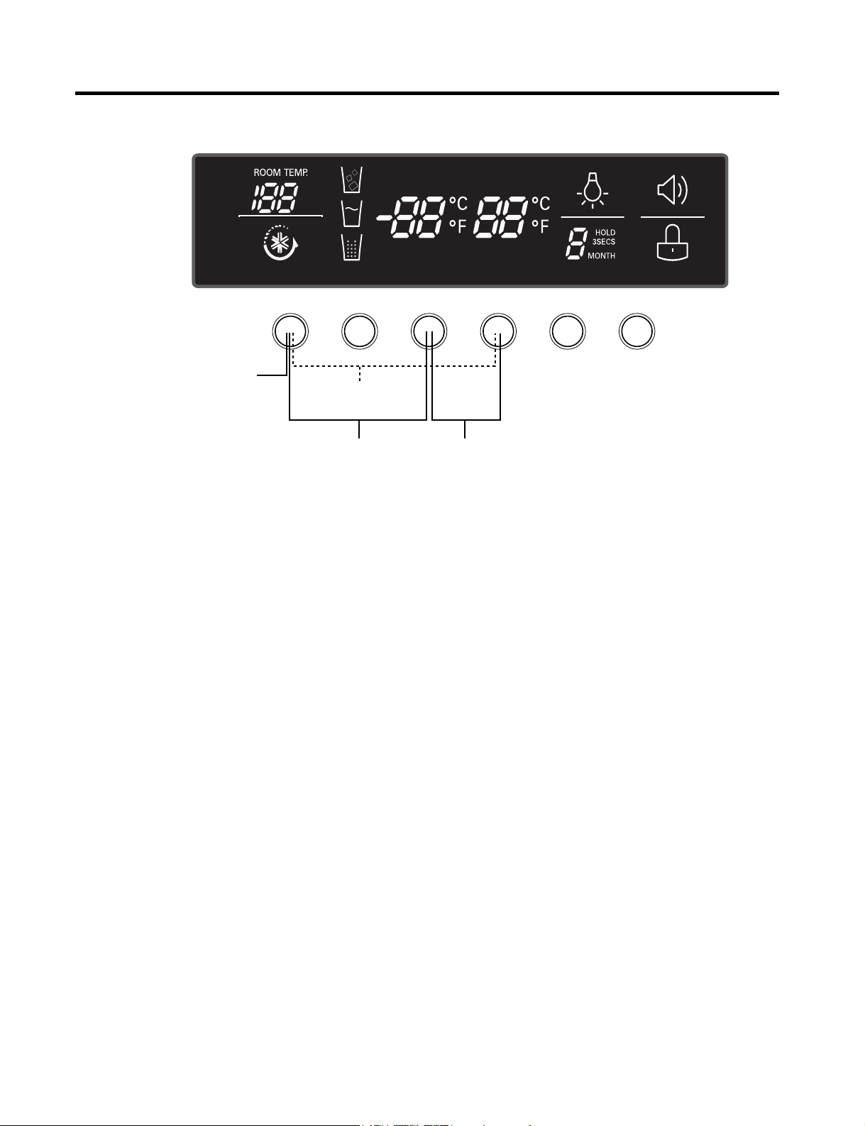
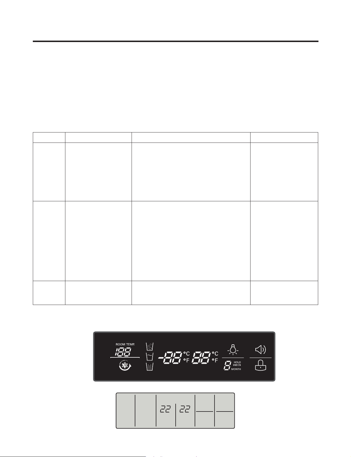
1. Monitor Panel
ICE PLUS DISPENSER FREEZER REFRIGERATOR LIGHT/FILTER ALARM/LOCK 3SECS
°C
°F
Ice Plus
function selection button
Dispenser selection
button
Temperature adjustment button
for freezer compartment
Alarm button and
Lock button
Lamp On/O button/
Filter status display RESET button
Temperature adjustment button
for refrigerator compartment
- 10 -
Page 11
1-3. Display Second Function
1. Buzzer sound mute Mode
The buzzer sound is set to OFF.
It activates by sounding the recognition sound of “Ding~” after pressing and holding ICE PLUS” button more than 5
seconds. It inactivates when resetting the mode power.
2. Display Power saving Mode
It places display in standby mode until door is opened.
Press “Freezer” and ICE PLUS” buttons simultaneously to turn all leds become ON and then OFF with the recognition
sound of “Ding~” after 5 seconds. (Be sure not to press only one button to work.)
Once the mode activates, the display is always OFF. Until door is opened or display button is pressed. When 30 seconds
has elapsed after closing door or pressing button, the display turns OFF. To deactivate this mode is same as the activation
methods. The mode inactivates when resetting the power.
3. Change Display Degree to Centigrade Mode from Fahrenheit Mode
To change temperature display from Fahrenheit to Celsius press and hold “FREEZER” and “REFRIGERATOR” buttons
simultaneously for more than 5 seconds. Do the same to convert back to Celsius.
4. Exhibition Mode
This function is available when exhibiting a refrigerator in the shopping moll.
Function is inserted with recognition sound “Ding ~” if pressing both the ICE PLUS” button and the “REFRIGERATOR”
button at the same time for more than 5 seconds. If function is inserted, all basic refreezing functions at the R/F room and
the Storage room (COMP, F-FAN, C-FAN) turns off and the display normally operates. However, the dispenser function
normally operates.
The DEMO stops if pressing the button during DISPLAY DEMO, DEMO stops and the display normally operates but
performs DEMO operation again if not pressing the button again for more than 30 seconds (DEMO: Display scenario
when using the display).
Release method is same as input method.
The mode is released if power is reset.
MICOM FUNCTION
- 11 -
ICE PLUS/JET FRZ DISPENSER FREEZER REFRIGERATOR FILTER/LIGHT LOCK
Display Power
saving Mode
Exhibition Mode
Change Display Degree from
Fahrenheit to Centigrade Mode
Buzzer sound
mute Mode
°C
°F
Page 12

MICOM FUNCTION
2. Description of Function
2-1-1. Function of Temperature Selection
Division Power Initially On 1st Press 2st Press 3th Press 4th Press
Setting
temperature
Temperature
Control
Freezer Control
Refrigeration
Control
* The temperature can vary ±3 °C depending on the load condition.
5
4
3
2
1
Medium Medium Max Max Min Medium Min
-2 °F -5 °F -8 °F7 °F1 °F
37 °F 34 °F 32 °F 46 °F 41 °F
5
4
3
2
1
5
4
3
2
1
5
4
3
2
1
5
4
3
2
1
❉ Whenever pressing button, setting is repeated in the order of (Medium) ➝ (Medium Max) ➝ (Max) ➝ (Min) ➝
(Medium Min).
• The actual inner temperature varies depending on the food status, as the indicated setting temperature is a target
temperature, not actual temperature within refrigerator.
• Refrigeration function is weak in the initial time. Please adjust temperature as above after using refrigerator for minimum
2~3 days.
• Freezer Notch is fixed “Medium Max” unconcerned with display Notch during ICE Making Control Mode and Ice Maker
Stop switch is selected with “ON”.
2-1-2. Outside temperature display function
1. Outside temperature sensor at the right Hinge Cover - U of refrigerator senses ambient temperature and displays the
outside temperature in the upper of “ROOM TEMP” text on the display part.
2. Ambient temperature is displayed up to 16°F ~ 120°F and displayed as “Lo” for less than 15°F and as “HI” for more than
121°F. If the ambient temperature sensor fails, it is displayed as “Er”.
3. Since display temperature of outside temperature is temperature sensed by the ambient sensor in the hinge U of the
refrigerator room, it may differ from the outside temperature display of other household electrical appliances.
- 12 -
Page 13

MICOM FUNCTION
2-1-3. Lock function (dispenser and display button lock)
1. In power application of refrigerator, the “LOCK” text is turned o at the right side of lock graphic of display with the lock
replease status.
2. If desiring to lock the dislay the dispenser and control panel, push on the LOCK button more than 3 seconds. LOCK text
is turned on at the right side of lock graphic of display with lock status.
3. The buzzer sound and control panel and dispenser function is not performed even if pressing display button other than
lock key in the lock status.
4. If desiring to release the lock status and pressing the lock button more than 3 seconds. “LOCK ” text is turned o at the
right side of lock graphic of display with the lock release status.
LOCK CONTROL
LOCK
DISPENSER & BUTTON
LOCK
DISPENSER & BUTTON
2-1-4. Filter condition display function
1. There is a replacement indicator light for the water lter cartridge on the dispenser.
2. Water lter needs replacement once six months.
3. Water lter light and “FILTER RESET HOLD 3SECS” text turn on to tell you need to replace the lter soon.
4. After replece the lter, press and hold the lock button more than 3seconds.
Then water lter light and “FILTER RESET HOLD 3SECS” text turn o with reset status.
Classication
Filter Status
Display
FILTER
FILTER RESET
- 1 3 -
Page 14
MICOM FUNCTION
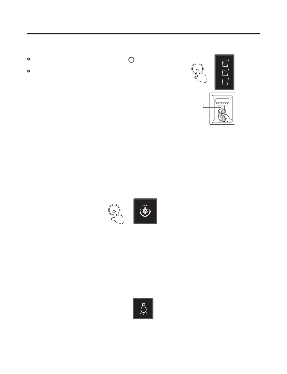
DISPENSER
2-2. Dispenser use selection
You can select water or ice.
Please select water, slice ice and square ice by pressing button as you
desire.
Please press the push button lightly by catching and pushing in cup.
• Each graphic is indicated for the selected function.
• “Tak! ” sounds if 5 seconds pass after ice comes out.
It is sound that the outlet of ice is closed.
REFERENCE :
Please wait for 2-3 second in order to take nal ice slices or drops
of water when taking out cup from the pressing switches after
taking ice or water.
DISPENSER
Pressing
Switch
2-3. ICE PLUS
Please select this function for prompt freezer.
• Function is repeated following below whenever pressing ICE PLUS
•
The arrow mark graphic remains at the On status after ickering 4 times when selecting Special Refrigeration ICE PLUS.
•ICE PLUS function automatically turns o
if a xed time passes.
LED
LED
ICE PLUS
2-4. Dispenser Light
• Dispenser switch or dispenser light button turn the dispenser light in the dispenser on and o.
• The dispenser light Function is repeated following below whenever pressing “FILTER RESET/LIGHT” button.
• If dispenser light continuously turns on more than 7 minutes with dispenser light button, the dispenser light turns o
automatically by compulsion.
Dispenser Iight ON/OFF
LED
- 1 4 -
Page 15

MICOM FUNCTION
2-5. ICE PLUS
1. ICE PLUS is function to improve cooling speed of the freezing room by consecutively operating compressors and
freezing room fan.
2. ICE PLUS is released if power failure occurs and then returns to the original status.
3. Temperature setting is not changed even if selecting the ICE PLUS.
4. The change of temperature setting at the freezing room or the cold storage room is allowed with ICE PLUS
selected and prrocessed.
5. The cold storage room operates the status currently set with ICE PLUS selected and procesed.
6. If selecting the ICE PLUS, the ICE PLUS function is released after continuously operating compressor and
freezing room fan.
7. If frost removal starting time is arrived during ICE PLUS, ICE PLUS operation is done only for the remaining
time after completion of frost removal when the ICE PLUS operation time passes 90 minutes. If passing 90
minutes, ICE PLUS operation is done only for 2 hours after completion of frost removal.
8. If pressing ICE PLUS button during frost removal, the ICE PLUS LCD or LED is turned on but if pressing the
ICE PLUS, compressor operates after the remaining time has passed.
9. If selection ICE PLUS within 7 minutes (delay for 7 minutes of compressor) after the compressor stops,
compressor operates after the remaining time has passed.
10. The freezing room fan motor operates at the high speed of RPM during operation of ICE PLUS.
- 15 -
Page 16

MICOM FUNCTION
Doors of freezing /
cold storage room
or home bar
BUZZER
Closing
Opening
Within
a minute
A minute
30
seconds30seconds30seconds
Opening
Closing Closing
3 Times 3 Times 3 Times 3 Times
2-8. Control of variable type of freezing fan
1. To increase cooling speed and load response speed, MICOM variably controls freezing room fan motor at the high speed
of RPM and standard RPM.
2. MICOM only operates in the input of initial power or ICE PLUS operation or load response operation for the high
speed of RPM and operates in the standard RPM in other general operation.
3. If opening doors of freezing / cold storage room or home bar while fan motor in the freezing room operates, the freezing
room fan motor normally operates (If being operated in the high speed of RPM, it converts operation to the standard
RPM). However, if opening doors of freezing room or home bar, the freezing room fan motor stops.
4. As for monitoring of BLDC fan motor error in the freezing room, MICOM immediately stops the fan motor by determining
that the BLDC fan motor is locked or poor if there would be position signal for more than 115 seconds at the BLDC motor.
Then it displays failure (refer to failure diagnosis function table) at the display part of refrigerator, the BLDC motor doesn’t
operate more. If you want to operate the BLDC motor, turn off and on power resource.
2-9. Control of cooling fan motor
1. The cooling fan motor performs ON/OFF control by linking with the COMP.
2. It controls at the single RPM without varying RPM.
3. Failure sensing method is same as in fan motor of freezing fan motor (refer to failure diagnosis function table for failure
display).
2-10. Door opening alarm
1. Buzzer generates alarm sound if doors are not closed even when more than a minute consecutively has passed with
doors of freezing / cold storage room or home bar opened.
2. Buzzer rings three times in the interval of 0.5 second after the first one-minute has passed after doors are opened and
then repeats three times of On/Off alarm in the cycle of every 30 seconds.
3. If all the doors of freezing / cold storage room or home bar are closed during door open alarm, alarm is immediately
released.
2-11. Ringing of button selection buzzer
1. If pressing the front display button, “Ding ~ “ sound rings.
- 16 -
Page 17

MICOM FUNCTION
2-12. Ringing of compulsory operation, compulsory frost removal buzzer
1. If pressing the test button in the main PCB, “Phi ~” sound rings.
2. In selecting compulsory operation, alarm sound is repeated and completed in the cycle of On for 0.2 second and Off for
1.8 second three times.
3. In selecting compulsory frost removal, alarm sound is repeated and completed in the cycle of On for 0.2 second , Off for
0.2 second, On for 0.2 second and Off for 1.4 second three times.
2-13. Frost removal function
1. Frost removal is performed whenever total operation time of compressor becomes 7 ~ 7.5 hour.
2. In providing initial power (or returning power failure), frost removal starts whenever total operation time of compressor
becomes 4 ~ 4.5 hour.
3. Frost removal is completed if temperature of a frost removal sensor becomes more than 5°C after starting frost removal.
Poor frost removal is not displaced if it does not arrive at 5°C even if two hours have passed after starting frost removal.
4. No removal is done if frost removal sensor becomes poor (snapping or short-circuit).
2-14. Refrigerator room lamp automatically off
• Refrigerator room lamp turn on and off by refrigerator door switch.
• If refrigerator room lamp continuously turns on more than 7 minutes, the refrigerator room lamp turns off automatically by
compulsion.
- 17 -
Page 18
MICOM FUNCTION
POWER
ON
COMP
ON
F-FAN
&
C-FAN
ON
R-STEP
MOTOR
DAMPER
ON
OPTICHILL
STEP
DAMPER
MOTOR
ON
FROST
REMOVAL
HEATER
OFF
FROST
REMOVAL
HEATER
ON
DAMPER
&
DUCT DOOR
&
OPTICHILL
HEATER ON
DAMPER
&
DUCT DOOR
&
OPTICHILL
HEATER OFF
0.3
sec.
6.0
sec.
0.3
sec.
0.3
sec.
0.3
sec.
POWER
ON
0.3
sec.
PIPE
&
DISP'
HEATER
OFF
0.3
sec.
COMP
ON
0.3
sec.
F-FAN
&
C-FAN
ON
0.3
sec.
R-STEP
MOTOR
DAMPER
ON
0.3
sec.
OPTICHILL
STEP
DAMPER
MOTOR
ON
PIPE
&
DISP'
HEATER
ON
TEST
SWITCH
(PRESS
Once)
OTHER
LOAD
OFF
COMP
ON
F-FAN
&
C-FAN
ON
R-STEP
MOTOR
DAMPER
ON
OPTICHILL
STEP
DAMPER
MOTOR
CLOSE
TEST
SWITCH
(PRESS
2 Times)
COMP
OFF
F-FAN
&
C-FAN
OFF
FROST
REMOVAL
HEATER
ON
R-STEP
MOTOR
DAMPER
CLOSE
0.3
sec.
0.3
sec.
0.3
sec.
0.3
sec.
0.3
sec.
0.3
sec.
0.3
sec.
0.3
sec.
0.3
sec.
0.3
sec.
0.3
sec.
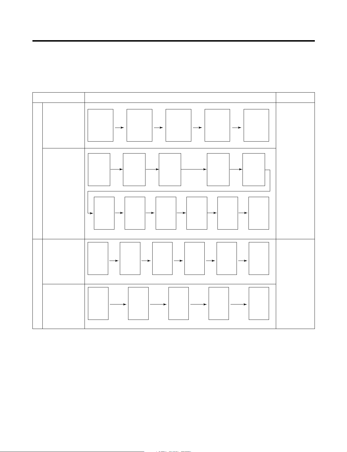
2-15. Sequential operation of built-in product
Built-in products such as compressor, frost removal heater, freezing room fan, Cooling Fan and step motor damper are
sequentially operated as follows for preventing noise and part damage occurred due to simultaneous operation of a lot of
parts in applying initial power and completing test.
Function Load Operation Sequence Remark
In applying Initial power TEST MODE
When temperature
of a frost removal
sensor becomes
more than 45°C
(In purchase,
movement)
When
temperature of a
frost removal
sensor becomes
less than 45°C
(In power failure,
service)
Test mode 1
(Compulsory
function)
Test mode 2
(Compulsory frost
removal)
If error occurs
during operation,
initial operation is
not done.
■
Sequence of
load operation
when closing
F-room and
R-room.
If pressing switch
once more in the
test mode 2 or
temperature of a
frost removal
sensor is more
than 5°C, it
immediately
returns to the test
mode for initial
operation
(COMP operates
after 7 minutes).
- 18 -
Page 19
Page 20
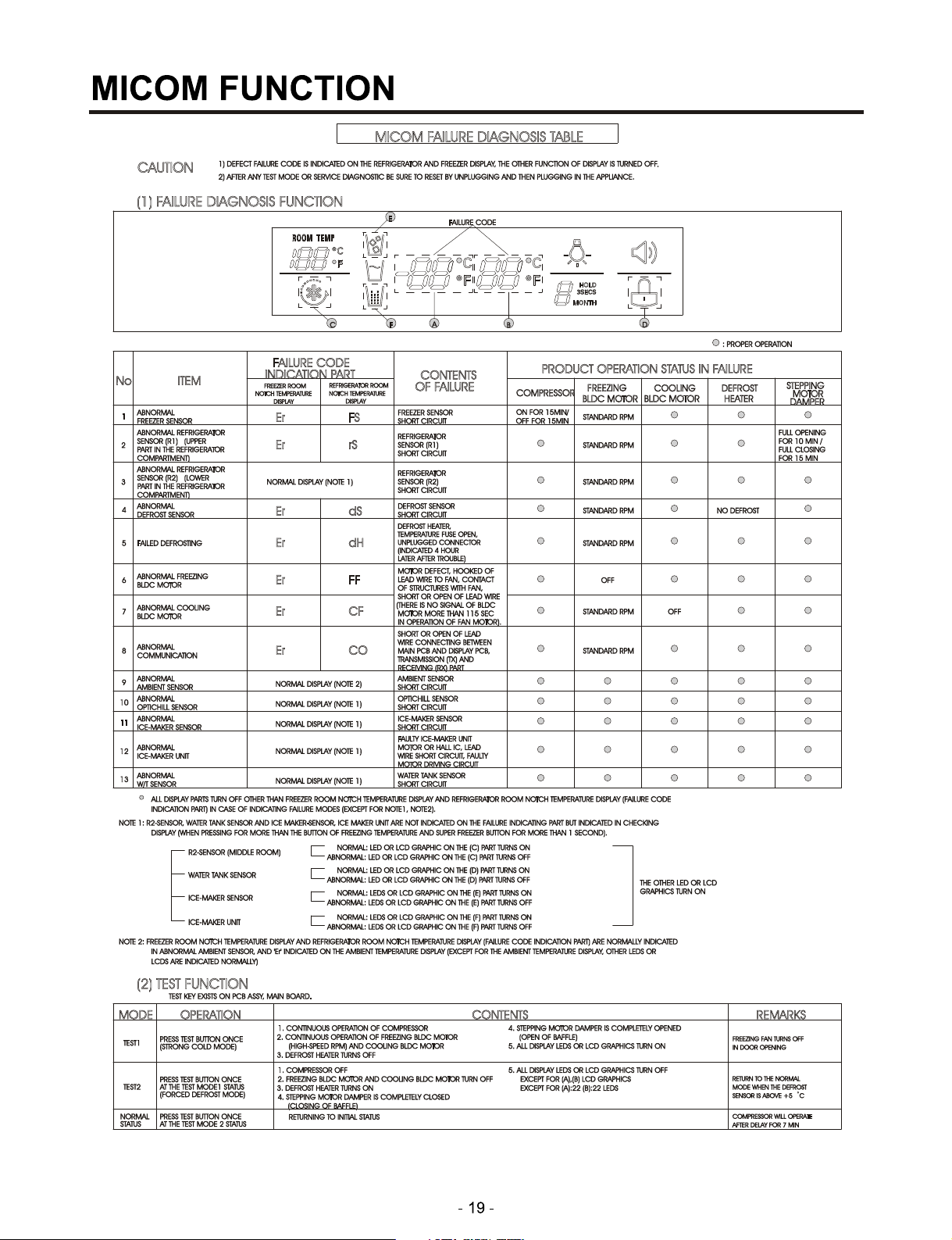
MICOM FUNCTION
Note1) R2-sensor, OptiChill sensor and water tank sensor, Ice maker-sensor, Ice maker Unit are not indicated on the failure
indicating part but indicated in checking Display(When pressing for more than the button of freezing temperature and
super freezer button for more than 1 second).
R2-sensor (middle room)
or Abnormal Drive Micom
Communication
OptChill sensor or
Water tank sensor
Ice-maing sensor
Ice-maker unit
Ambient sensor
(Better1 Model Only)
Note2) Freezer room notch temperature display and refrigerator room notch temperature display(Failure code indication
part) are normally indicated in abnormal ambient sensor, and “Er” indicated on the amvient temperature
display(except for the ambient temperature display, other LEDs or LCDs are indicated normally)
✻ LCD(LED) check function: If simultaneously pressing express freezer button and freezing temperature adjustment button
for a second, a back light is turned on and all display LCD(LED) graphics on. If releasing the
button, the LCD(LED) graphic displays the previous status, the back light is turned off (LCD
graphic and back light ON/OFF check).
Normal: LED or LCD graphic on the (C) part turns on
Abnormal: LED or LCD graphic on the (C) part turns off
Normal: LED or LCD graphic on the (D) part turns on
Abnormal: LED or LCD graphic on the (D) part turns off
Normal: LED or LCD graphic on the (E) part turns on
Abnormal: LED or LCD graphic on the (E) part turns off
Normal: LED or LCD graphic on the (F) part turns on
Abnormal: LED or LCD graphic on the (F) part turns off
Normal: LED or LCD graphic on the (G) part turns on
Abnormal: LED or LCD graphic on the (G) part turns off
The other LED or
LCD Graphics
Turn On.
- 20 -
Page 21
MICOM FUNCTION
2-17. Test Function
1. The purpose of test function is to check function of the PWB and product and to search for the failure part at the failure
status.
2. Test button is placed on the main PCB of refrigerator (test switch), and the test mode will be nished after maximum 2
hours irrespective of test mode and then is reset to the normal status.
3. Function adjustment button is not perceived during performance of test mode.
4. In nishing test mode, always pull the power cord out and then plug-in it again for the normal state.
5. If nonconforming contents such as sensor failure are found during performance of test mode, release the test mode and
display the failure code.
6. Even if pressing the test button during failure code display, test mode will not be performed.
skrameRstnetnoCnoitarepOedoM
Test 1
Test 2
Normal
Status
Press test button once
(strong cold mode)
Press test button once at
the test mode 1 status
(forced defrost mode)
Press test button once at
the test mode 2 status
1. Continuous operation of compressor
2. Continuous operation of freezing bldc motor
(high-speed RPM) and cooling bldc motor
3. Defrost heater turns o
4. Stepping motor damper is completely opened
(open of bae)
5. Optichil stepping motor damper is completely
closed.
6. All display LEDs or LCD graphics turn on.
1. Compressor OFF
2. Freezing bldc motor and cooling bldc motor
turn o
3. Defrost heater turns on
4. Stepping motor damper is completely closed
(closing of bae)
5. OptiChil stepping motor damper is completely
closed.
6. All display LEDs or LCD graphics turn o.
GR-L267BV(T)RA, GR-L267BV(T,S)PA :
Except for (A)22 (B)22 LEDs
GR-L267BV(T)R : Except for only middle
Notch Bar Graphics
Return to the initial status.
Freezing fan turns o in
door opening.
Return to the normal mode
when the defrost sensor is
above +5 °C
Compressor will operate
after delay for 7 minutes
TEST MODE1 STATUS DISPLAY
°
C
°F
TEST MODE2 STATUS DISPLAY
- 2 1 -
Page 22

MICOM FUNCTION
2-18. Function of dispenser and water dispenser built-in
1. This is function allowing ice and water to come outside without opening door.
2. If pressing the dispenser switch (rubber button) after selecting ice (cube ice, crushed ice) or water, ice and water
equivalent to each come out. However, the duct doors are opened by electrical solenoid valve (Duct Door Solenoid) if
pressing the press switch in case of selecting ICE. If pressing the dispenser press switch and then detaching the hands,
the duct door is closed after it is opened for 5 seconds.
3. Function allowing ice and water to come stops if freezing room doors are opened.
4. If there is no Off signal even when 3 minutes have passed while pressing the dispenser press switch after selecting ice
(cube ice, crushed ice) or water, geared motor and solenoid (Cube, Water) is automatically turned off. However, the
solenoid (duct door) is stop 5 seconds after Off (to prevent short-circuit of a coil due to overheat of solenoid).
5. Dispenser Lamp On/Off function
Lamp on the dispenser part is turned on if pressing the dispenser press switch after selecting ice (cube ice, crushed ice)
or water. If detaching the hands, it is turned off.
6. Selection function of water/crushed/ cube ice
1) This is function to allow selection of water/crushed/ cube ice function depending on user’s selection. Display and
selection is done if pressing the dispenser selection button.
2) In the initial Power On, cube ice is automatically selected.
3) In selecting cube ice, geared motor is operated so that crushed ice can be supplied outside if pressing the press switch
when ice is formed in the ice storage container (Bank, Ice).
4) In selecting cube ice, geared motor is operated so that cube ice can be supplied outside if pressing the press switch
when ice is formed in the ice storage container (Bank, Ice).
7. Water dispenser function
1) It is displayed for selection if user selects water at the function adjustment part.
2) Water dispenser function is a type directly connected to a water pipe. The water solenoid valve built-in at the right side
of the Back plate is opened so that water can be supplied if selecting Water from the function adjustment part and then
pressing the press switch.
- 22 -
Page 23
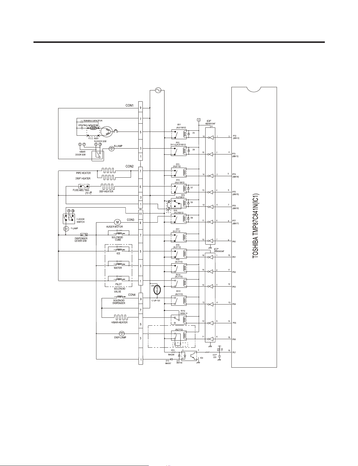
EXPLANATION FOR MICOM CIRCUIT
1. Explanation for PWB circuit
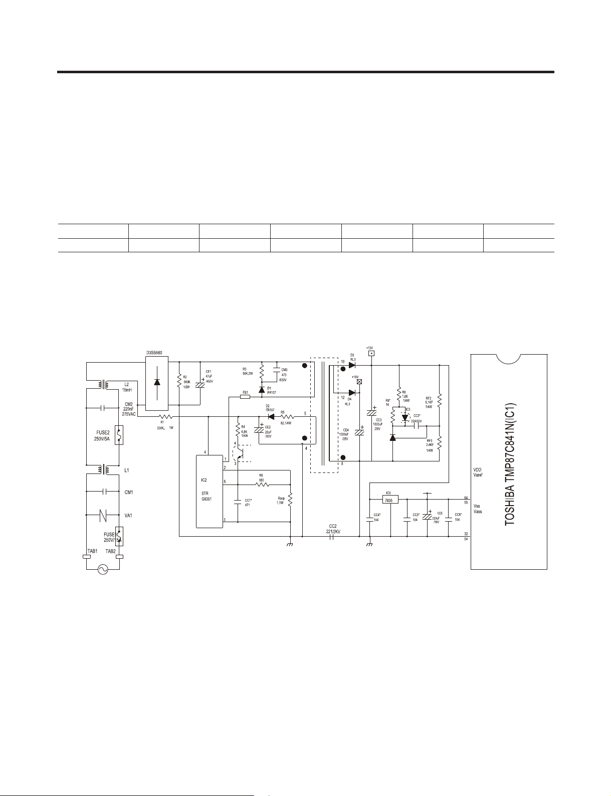
1-1. Power circuit
The power
to DC, a switch (IC2) switching the DC voltage, a transformer, and a feedback circuit (IC3 and IC4).
Caution : Since high voltage (160 Vdc) is maintained at the power terminal, wait at least 3 minutes after unplugging the
Voltage of every part is as follows:
circuit includes a Switched Mode Power Supply (SMPS). It consists of a rectier (BD1 and CE1) converting AC
appliance to check the voltages to allow the current to dissipate.
Part VA1 CE1 CE2 CE3 CE4 CE5
Voltage 120 Vac 160 Vdc 14 Vdc 12 Vdc 15.5 Vdc 5 Vdc
- 2 3 -
Page 24
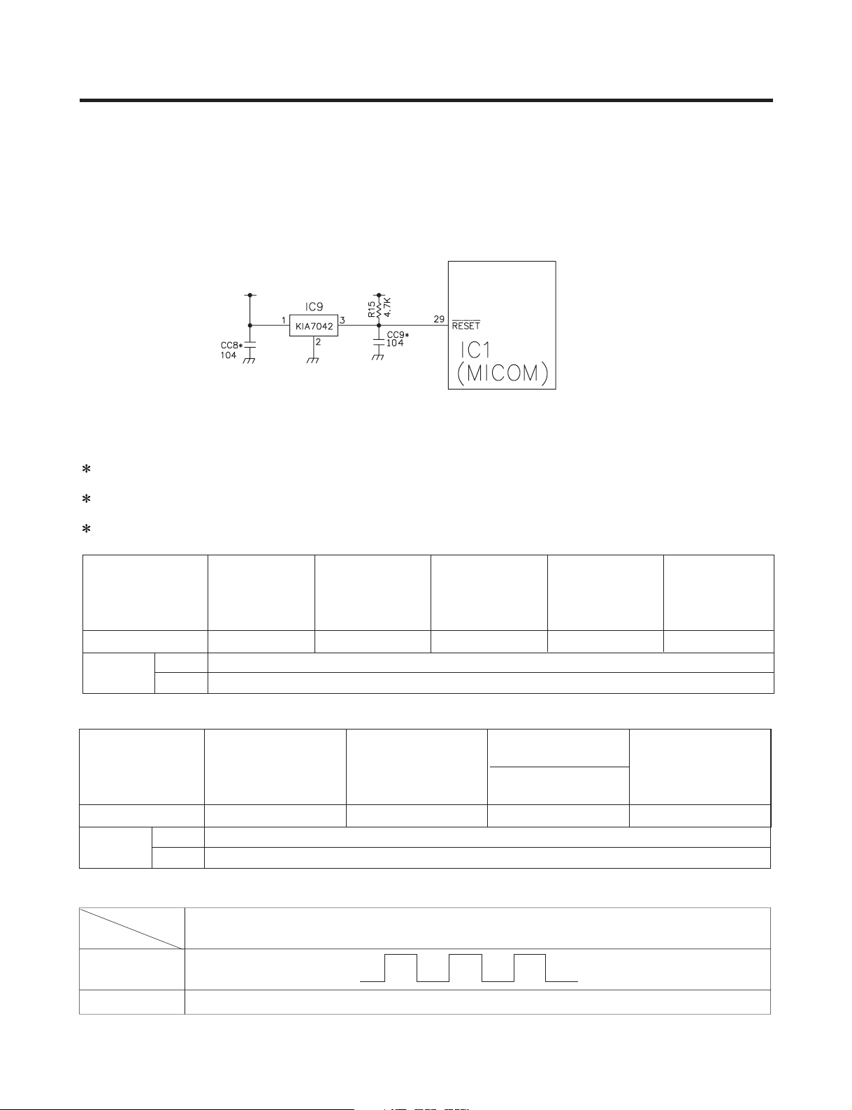
1-3. Reset circuit
The RESET circuit allows various parts of the MICOM, such as RAM, defrosting, etc., to be restarted from the initial state
when power is interrupted or restored. A LOW signal applied to the reset terminal for 10 ms causes the MICOM to reset
itself. During normal operation, the voltage at the reset terminal is 5 Vdc. If the reset fails, the MICOM will not operate.
1-4. Load/dispenser operation, door opening circuit
1. LOAD DRIVING CIRCUIT
The fan operates at the regular speed even if the door of the refrigerator or freezer is opened. When the doors are closed,
the fan reverts to its original speed.
(A), (B), (C), and (D) of door switch for the freezer or refrigerator are connected to the door open sensing circuit in paralle
toward both ends of switch to determine door open at MICOM.
In the TEST mode, the fan will stop if any door is opened. It will resume operation when the door is closed.
Type of Load Compressor
Measuring part (IC6) IC6-16 IC6-13 IC6-12 IC6-15 IC6-14
Status
1) Check load driving status
Type of Load
Measuring part IC6-11 IC6-10 IC7-15 IC7-13
Status
2) Lever Switch sensing circuit
Measuring part
Lever S/W
On(Press)
GEARED
MOTOR
Frost Removal
Heater
SOLENOID
CUBE
5 V
0 V
AC Converting
Relay
V1nihtiWNO
V21FFO
V1nihtiWNO
V21FFO
IC1(Micom) (No. 16)
V5FFO
Refrigerator
WATER VALVE
WATER
LAMP
SOLENOID
DISPENSER
(60 Hz)
Dispensor
Heater
-24-
Page 25
EXPLANATION FOR MICOM CIRCUIT
-25-
Page 26

EXPLANATION FOR MICOM CIRCUIT
3. Door opening sensing circuit
Measuring part
IC1 (MICOM) No. (44, 45) / (45, 46) / (47, 48) Pin
Door of Freezer / Refrigerator
Since door switches (A) and (B) are interconnected, if either fails, the other will not respond properly.
If either switch fails, the light will not come on.
)sutatsffOtaerasdnehtobtahctiwS.D-C,B-A(V5gnisolC
)sutatsnOtaerasdnehtobtahctiwS.D-C,B-A(V0gninepO
- 26 -
Page 27
EXPLANATION FOR MICOM CIRCUIT
A
B
C
D
F
E
RW1
10KF
CE18
R73
CC32
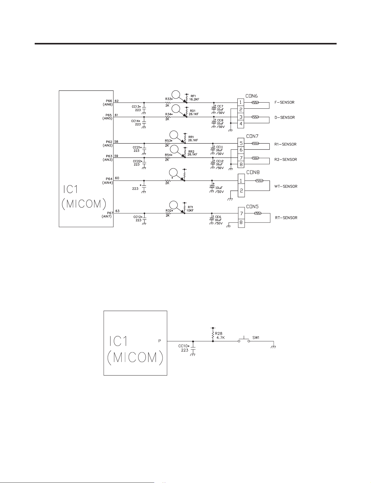
1-5. Temperature sensing circuit
1-6. Switch entry circuit
The following circuits are sensing signal form the test switch, damper motor reed switch for testing and diagnosing the
refrigerator.
47
46
- 27 -
Page 28
EXPLANATION FOR MICOM CIRCUIT
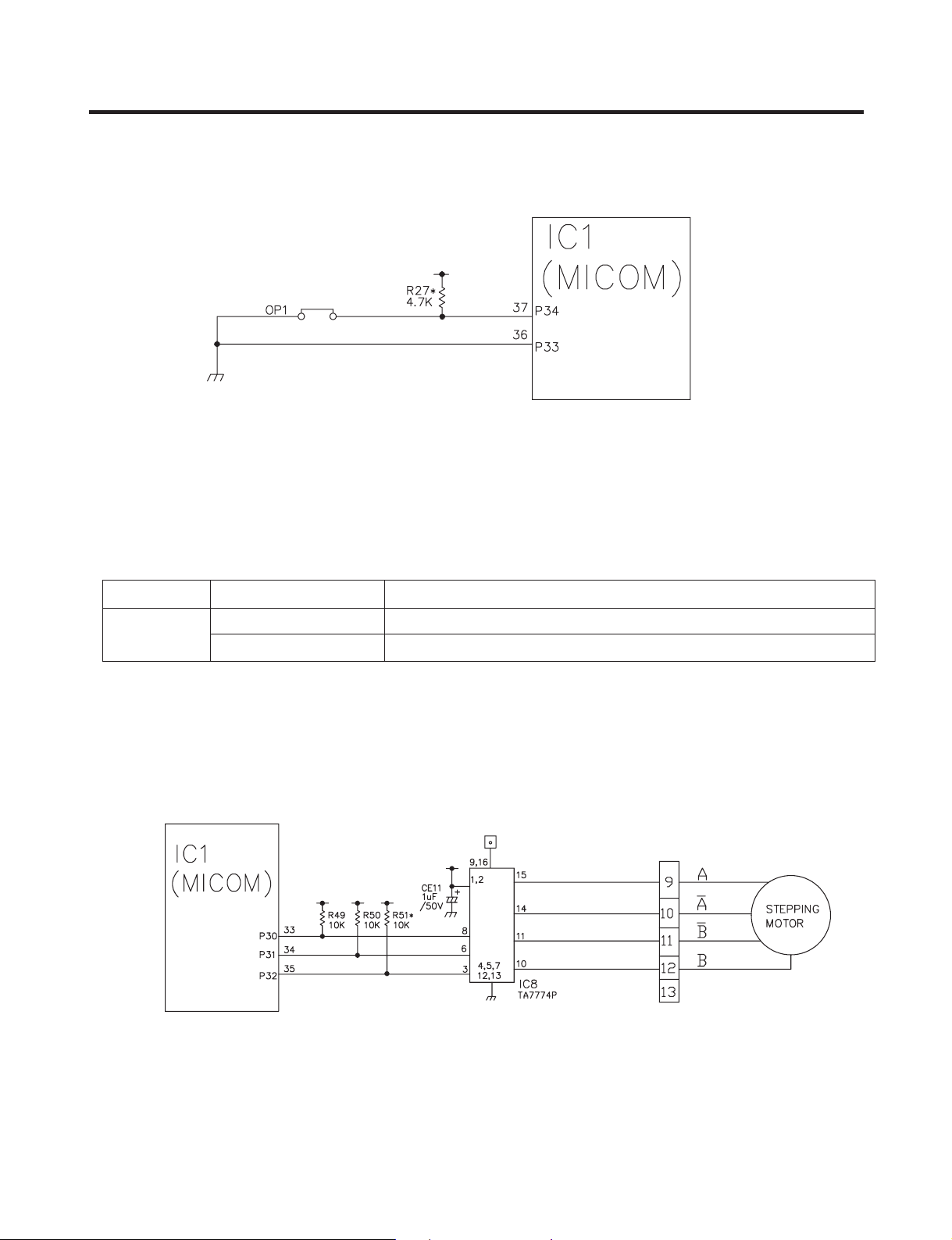
1-7. Option designation circuit (model separation function)
The circuits shown above vary according to which features are included on your particular model.
These circuits are preset at the factory and cannot be altered.
•
NOTE: The chart makes absolutely no sense. You have Optichill no matter which way the connection is set.
OP1
1-8. Stepping motor operation circuit
dradnatSnoitacilppAsutatSnoitcennoCnoitarapeS
tsixellihCitpOnoitcennoC
nodllihCitpOTUO ’t exist
-28-
Page 29
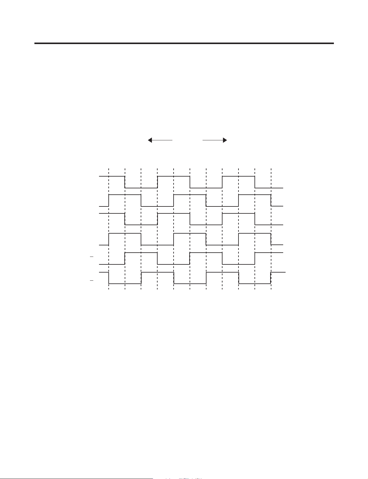
EXPLANATION FOR MICOM CIRCUIT
INA
INB
A
B
A
B
WC )noitator evitisoP()noitator esreveR( WCC
The motor is driven by magnetism formed in the areas of the coils and the stator. Rotation begins when a HIGH signal is
applied to MICOM Pin 33 of IC10 (TA7774F). This causes an output of HIGH and LOW signals on MICOM pins 34 and 35.
Explanation) The stepping motor is driven by sending signals of 3.33 mSEC via MICOM pins 33, 34, and 35, as shown in
the chart below. These signals are output via terminals 10, 11, 14, and 15 via input terminals 3, 6, and 8 of
IC10 (TA7774F), the motor drive chip. The output signals allow the coils wound on each phase of the stator to
form a magnetic eld, which causes rotation. Input to the terminals INA and INB of IC10 as shown in the chart
below drives the motor.
-29-
Page 30
EXPLANATION FOR MICOM CIRCUIT
1-9. Fan motor driving circuit (freezer, mechanical area)
1. The circuit cuts all power to the fan drive IC, resulting in a standby mode.
2. This circuit changes the speed of the fan motor by varying the DC voltage between 7.5 Vdc and 16 Vdc.
3. This circuit stops the fan motor by cutting o power to the fan when it senses a lock-up condition.
b
trapetrapbtrapd,a
sselroV2sselroV2V5FFOrotoM
V61~8V41~21V3~2NOrotoM
a
e
d
-30-
Page 31

EXPLANATION FOR MICOM CIRCUIT
Temperature compensation table at the refrigerator is as follows:
►
Modication
resistance
Current
resistance
470 Ω [0.9 ° F] [1.8 °F] [2.7 ° F] [3.6 °F] [4.5 °F] [5.4 °F] [6.3 °F] [7.2 °F] [8.1 ° F] [9 °F]
2 k Ω [0.9 °F] [0.9 °F] [1.8 °F] [2.7 °F] [3.6 °F] [4.5 °F] [5.4 ° F] [6.3 °F] [7.2 °F] [8.1 °F]
3.3 k Ω [1.8 °F] [0.9 °F] [0.9 °F] [1.8 °F] [2.7 °F] [3.6 °F] [4.5 °F] [5.4 ° F] [6.3 ° F] [7.2 °F]
5.6 k Ω [2.7 °F] [1.8 °F] [0.9 °F] [0.9 °F] [1.8 ° F] [2.7 °F] [3.6 ° F] [4.5 °F] [5.4 °F] [6.3 °F]
8.2 k Ω [3.6 °F] [2.7 °F] [1.8 °F] [0.9 °F] [0.9 °F] [1.8 ° F] [2.7 °F] [3.6 ° F] [4.5 °F] [5.4 °F]
Refrigerator
470 Ω 2 k Ω 3.3 k Ω 5.6 k Ω 8.2 k Ω 10 k Ω 12 k Ω 18 k Ω 33 k Ω 56 k Ω 180 k Ω
No 0.5 ° C 1 ° C 1.5 ° C 2 ° C 2.5 °C 3 °C 3.5 °C 4 °C 4.5 °C 5 ° C
change
0.5 ° C No 0.5 ° C 1 ° C 1.5 °C 2 ° C 2.5 °C 3 ° C 3.5 °C 4 ° C 4.5 °C
Down change
1 °C 0.5 °C No 0.5 ° C 1 ° C 1.5 °C 2 °C 2.5 °C 3 °C 3.5 ° C 4 ° C
Down
1.5 ° C 1 ° C 0.5 ° C No 0.5 ° C 1 °C 1.5 ° C 2 ° C 2.5 ° C 3 ° C 3.5 °C
Down Down Down
2 °C 1.5 °C 1 ° C 0.5 ° No 0.5 ° C 1 ° C 1.5 ° C 2 ° C 2.5 ° C 3 °C
Down Down Down
Up Up Up Up Up Up Up Up Up Up
Up Up Up Up Up Up Up Up Up
Down
change
Up Up Up Up Up Up Up Up
change
Drop
Up Up Up Up Up Up Up
change
Up Up Up Up Up Up
(RCR1) 2.5 °C 2 °C 1.5 ° C 1 ° C 0.5 ° C No 0.5 ° C 1 ° C 1.5 ° C 2 ° C 2.5 °C
10 k Ω [4.5 °F] [3.6 °F] [2.7 °F] [1.8 °F] [0.9 °F] [0.9 °F] [1.8 °F] [2.7 °F] [3.6 °F] [4.5 °F]
Down Down Down Down Down
3 °C 2.5 °C 2 ° C 1.5 °C 1 °C 0.5 °C No 0.5 °C 1 °C 1.5 °C 2 ° C
12 k Ω [5.4 °F] [4.5 °F] [3.6 °F] [2.7 °F] [1.8 °F] [0.9 °F] [0.9 ° F] [1.8 °F] [2.7 °F] [3.6 °F]
Down Down Down Down Down Down
3.5 ° C 3 ° C 2.5 ° C 2 ° C 1.5 °C 1 °C 0.5 °C No 0.5 °C 1 °C 1.5 °C
18 k Ω [6.3 °F] [5.4 °F] [4.5 °F] [3.6 °F] [2.7 °F] [1.8 °F] [0.9 °F] [0.9 °F] [1.8 °F] [2.7 °F]
Down Down Down Down Down Down Down
4 °C 3.5 °C 3 ° C 2.5 °C 2 °C 1.5 °C 1 °C 0.5 °C No 0.5 °C 1 °C
33 k Ω [7.2 °F] [6.3 °F] [5.4 °F] [4.5 °F] [3.6 °F] [2.7 °F] [1.8 °F] [0.9 ° F] [0.9 °F] [1.8 °F]
Down Down Down Down Down Down Down Down
4.5 ° C 4 ° C 3.5 ° C 3 ° C 2.5 °C 2 °C 1.5 °C 1 °C 0.5 °C No 0.5 ° C
56 k Ω [8.1 °F] [7.2 °F] [6.3 °F] [5.4 °F] [4.5 °F] [3.6 °F] [2.7 °F] [1.8 ° F] [0.9 °F] [0.9 °F]
Down Down Down Down Down Down Down Down Down
5 °C 4.5 °C 4 ° C 3.5 °C 3 °C 2.5 °C 2 °C 1.5 °C 1 °C 0.5 ° C No
180 k Ω [9 ° F] [8.1 °F] [7.2 °F] [6.3 °F] [5.4 °F] [4.5 °F] [3.6 ° F] [2.7 °F] [1.8 ° F] [0.9 °F]
Down Down Down Down Down Down Down Down Down Down
Temperature compensation at the freezer is performed the same as at the refrigerator. The value for the freezer is twice
►
that of the refrigerator.
This circuit enters the necessary level of temperature compensation for adjusting the appliance. The method is the same
►
for every model in this appliance family.
change
Up Up Up Up Up
change
Up Up Up Up
change
Up Up Up
change
Up Up
change
Up
change
-31-
Page 32

EXPLANATION FOR MICOM CIRCUIT
2. Compensation circuit for temperature at freezer
Temperature compensation in CUT
JCR1 +1 °C [+1.8 ° F]
JCR2 +1 °C [+1.8 ° F]
JCR3 -1 ° C [-1.8 °F]
JCR4 -1 ° C [-1.8 °F]
+2 ° C [+3.6 °F]
-2 °C [-3.6 °F]
Compensation Compensation
for weak-cold for over-cold
JCR3 JCR4 JCR1 JCR2
CUT +1 ° C [+1.8 ° F]
CUT CUT +2 ° C [+3.6 °F]
CUT CUT CUT +1 °C [+1.8 °F]
CUT CUT CUT CUT 0 ° C [0 °F]
Temperature compensation value
at refrigerator
0 °C (In shipment from factory)
1-TUC °C [-1.8 ° F]
1-TUC °C [-1.8 ° F]
1+TUC °C [+1.8 °F]
2-TUCTUC °C [-3.6 ° F]
0TUCTUC °C [0 ° F]
0TUCTUC °C [0 ° F]
0TUCTUC °C [0 ° F]
0TUCTUC °C [0 ° F]
1-TUCTUCTUC °C [-1.8 ° F]
Remarks
• This circuit allows adjustment of the set temperature for compensation by changing jumpers at locations JCR1~JCR4.
-32-
Page 33

EXPLANATION FOR MICOM CIRCUIT
Main MICOM LCD(LED)dedicated MICOM
DC 12V
GND
Transmission (error status)
Reception (notch status)
Main PCB L/Wire FD/H(4-wires) Display PCB
1-11. Communication circuit and connection L/Wire between main PCB and display PCB
The following communication circuit is used for exchanging information between the main MICOM of the Main PCB and the
dedicated MICOM of the LED (LCD) Display PCB.
A bi-directional lead wire assembly between the two boards is required for the display to function properly.
Poor communication occurs if a continuous information exchange fail to continue for more than 2 minutes between main
MICOM of main PCB and LCD (LED) dedicated MICOM for LCD (LED) control of display PCB.
°
C
°F
-33-
Page 34

EXPLANATION FOR MICOM CIRCUIT
2) Sensor resistance characteristics table
Measuring Temperature (°C) Freezing Sensor
-20 ° k 3.22C Ω 77 k Ω
-15 ° k 9.61C Ω 60 k Ω
-15 ° k 0.31C Ω 47.3 k Ω
-5 ° k 1.01C Ω 38.4 k Ω
0 ° k 8.7C Ω 30 k Ω
+5 ° k 2.6C Ω 24.1 k Ω
+10 ° k 9.4C Ω 19.5 k Ω
+15 ° k 9.3C Ω 15.9 k Ω
+20 ° k 1.3C Ω 13 k Ω
+25 ° k 5.2C Ω 11 kΩ
+30 ° k 0.2C Ω 8.9 k Ω
+40 ° k 4.1C Ω 6.2 k Ω
+50 ° k 8.0C Ω 4.3 k Ω
Cold storage sensor 1&2
Frost removal sensor, Outside sensor
Resistance value allowance of sensor is ±5%.
►
When measuring the resistance value of the sensor, allow the temperature of that sensor to stabilize for at least 3 minutes
►
before measuring. This delay is necessary because of the sense speed relationship.
Use a digital tester to measure the resistance. An analog tester has to great a margin of error.
►
Resistance of the cold storage sensor 1 and 2 shall be measured with a digital tester after separating CON8 of the PWB
►
ASSEMBLY and the MAIN part.
Resistance of the freezing sensor shall be measured with a digital tester after separating CON7 of the PWB ASSEMBLY
►
and the MAIN part.
-34-
Page 35

EXPLANATION FOR MICOM CIRCUIT
-35-
Page 36

EXPLANATION FOR MICOM CIRCUIT
-36-
Page 37

EXPLANATION FOR MICOM CIRCUIT
-37-
Page 38

-38-
Page 39

EXPLANATION FOR MICOM CIRCUIT
-39-
Page 40

-40-
Page 41

-41-
Page 42

1. Working Principles
1-1. Ice Maker Working Principles
1-2. Dispenser Working Principles
1. This function is available in Models LSC27926**, where water and ice are
available without opening freezer compartment door.
2. “Crushed Ice ” is automatically selected when power is initially applied or reapplied after power cut.
3. When dispenser selection switch is continuously pressed, light is on in the following sequence:
“Water ” “Cube Ice ” “Crushed Ice ”.
4. Lamp is on when dispenser rubber button is pressed and vice versa.
5. When dispenser crushed ice rubber button is pressed, dispenser solenoid and geared motor work so that crushed ice can
be dispensed if there is ice in the ice bank.
6. When dispenser cube ice rubber button is pressed, dispenser solenoid, cube ice solenoid and geared motor work so that
cube ice can be dispensed if there is ice in the ice bank.
7. When dispenser water rubber button is pressed, water valve opens and water is supplied if water valve is normally
installed on the right side of the machine room.
8. Ice and water are not available when freezer door is open.
ICE MAKER AND DISPENSER WORKING PRINCIPLES AND REPAIR
• Level Ice Maker Cube Mould for “ Initial Control”
after power is input.
Power Input
Initial Control
Ice Making Control
Ice Ejection Control
Water Supply Control
Test Control
• Wait until the water in the cube mould is frozen
after ice maker starts operation.
• Check ice bank is full of ice by rotating ice ejection
motor in normal and reverse direction and eject ice into
the ice bank if ice bank is not full.
• This is for refrigerator assembly line and service. When “ice making test switch” is pressed,
it operates in the following steps: initial ice ejection water supply control steps.
• Conduct “Ice Making Control ” after supplying water into the ice maker
cube mould by operating water valve.
-42-
Page 43

ICE MAKER AND DISPENSER WORKING PRINCIPLES AND REPAIR
2. Function of Ice Maker
2-1. Initial Control Function
1. When power is initially applied or reapplied after power cut, it detects level of ice maker cube mould after completion of
MICOM initialization. The detecting lever moves up and down.
2. The level of ice maker cube mould is judged by output signal, high and low signal, of Hall IC. Make the cube mould to be
horizontal by rotating ice ejection motor in normal or reverse direction so that High/Low signal can be applied to MICOM
Pin No. 42.
3. If there is no change in signals one minute after the geared motor starts to operate, it stops icemaker operation and check
the signal every hour. It resets initialization of icemaker when it becomes normal.
4. It judges that the initial control is completed when it judges the ice maker cube mould is horizontal.
5. Ice ejection conducts for 1 cycle irrespect of ice in the ice bank when power is initially applied.
2-2. Water Supply Control Function
1. This is to supply water into the ice maker cube mould by operating water valve in the machine room when ice ejection
control is completed and ice maker mould is even.
2. The quantity of water supplied is determined by DIP switch and time.
<Water Supply Quantity Table>
LSC27926**
No
1
2
3
4
5
6
7
8
DIP SWITCH SETTING
S1 S2 S3
OFF OFF OFF 6.5 SEC
ON OFF OFF 5.5 SEC
OFF ON OFF 6 SEC
ON ON OFF 7 SEC
OFF OFF ON 7.5 SEC
ON OFF ON 8 SEC
OFF ON ON 9 SEC
ON ON ON 10 SEC
WATER
SUPPLY TIME
* The quantity of water
* DIP switch is on the main
REMARKS
supplied depends on DIP
switch setting conditions
and water pressure as it
is a direct tap water
connection type. (the
water supplied is
generally 80 cc to 120 cc)
PWB.
3. If water supply quantity setting is changed while power is on, water supplies for the amended time. If DIP switch is
changed during water supply, water shall be supplied for the previous setting time. But it will supply for the amended time
from the next supply.
4. When water supply signal is applied to water and ice valves at the same time during water supply, water shall be supplied
to water valve. If water supply signal is applied to ice valve during water supply, water shall be supplied to both water and
ice valves.
2-3. Ice Making Control Function
1. Ice making control is carried out from the completion of water supply to the completion of ice making in the cube mould.
Ice making sensor detects the temperature of cube mould and completes Ice making. (ice making sensor is xed below
ice maker cube mould)
2. Ice making control starts after completion of water supply control or initial control.
3. It is judged that ice making is completed when ice making sensor temperature reaches at -8° C after 100 minutes when
water is supplied to ice maker cube mould.
4. It is judged that ice making is completed when ice maker sensor temperature reaches below -12 ° C after 20 minutes in
condition 3.
-43-
Page 44

ICE MAKER AND DISPENSER WORKING PRINCIPLES AND REPAIR
Bank is
not full
HALL IC
OUTPUT
SIGNALS
Bank is
full
HALL IC
OUTPUT
SIGNALS
ICE CHECKING
AXIS
ICE CHECKING LEVEL 30 °
Maximum tilting
point
Ice making
(Original point)
Lock
2±1 sec
9±3 sec
8±3 sec
noitcejE ecIgnikcehC ecI
Lock
Horizontal
Conditions
Level Retrun
Conditions
2-4. Ice Ejection Control Function
1. This is to eject ice from ice maker cube mould after ice making is completed.
2. If Hall IC signal is on within 3.6 seconds after ice ejection motor rotates in normal direction, it does not proceed ice
ejection but waits. If the ice bank is full, ice ejection motor rotates in normal direction in every hour to check the condition
of ice bank. If the ice bank is not full, the water supply control starts after completion of ice ejection control. If the ice bank
is full, ice ejection motor rotates in reverse direction and sops under ice making or waiting conditions.
3. If ice bank is not full, ice ejection starts. The cube mould tilts to the maximum and ice is separated from the mould and ice
checking lever raises.
4. Ice ejection motor stops for 1 second if Hall IC signal changes from OFF (low) to ON (high) after 3.6 seconds when ice
ejection motor rotates in normal direction. If there is no change in Hall IC signals within 1 minute after ice ejection motor
operates, ice ejection motor stops as ice ejection motor or hall IC is out of order.
5. If ice ejection motor or Hall IC is abnormal, ice ejection motor rotates in normal direction to exercise initial operation. It
resets the ice maker if ice ejection motor or Hall IC is normal.
6. The mould stops for 1 second at maximum tilted conditions.
7. The mould returns to horizontal conditions as ice ejection motor rotates in reverse direction.
8. When the mould becomes horizontal, the cycle starts to repeat:
Water Supply Ice Making Ice Ejection Mould Returns to Horizontal
-44-
Page 45

ICE MAKER AND DISPENSER WORKING PRINCIPLES AND REPAIR
2-5 Test Function
1. It is to force the operation during operation test, service, and cleaning. The test switch is mounted under the automatic
ice maker. The test function starts when the test switch is pressed for more than 0.5 second.
2. Test button does not work during ice ejection and water supply. It works when it is in the horizontal conditions. If mould is
full of ice during test function operation, ice ejection control and water supply control do not work.
3. When test switch is pressed for more than 0.5 second in the horizontal conditions, ice ejection starts irrespect of the
mould conditions. Water shall be splashed if test switch is pressed before the water in the mould freezes. Water shall be
supplied while the mould returns to the horizontal conditions after ice ejection. Therefore the problems of ice ejection,
returning to the horizontal conditions, and water supply can be checked by test switch. When test function performs
normally, buzzer sounds and water supply shall carry out. Check it for repair if buzzer does not sound.
4. When water supply is completed, the cycle operates normally as follows: Ice making
horizontal conditions Water supply
5. Remove ice from the ice maker cube mould and press test switch when ice maker cube mould is full of ice as ice ejection
and water supply control do not work when cube mould is full of ice.
Ice ejection
2-6. Other functions relating to freezer compartment door opening
1. When freezer door is open, ice dispenser stops in order to reduce noise and ice drop.
2. When freezer door is open during ice ejection and cube mould returning to horizontal condition, ice ejection and cube
mould level return proceed.
3. When freezer door is open, geared motor and cube ice solenoid immediately stop and duct door solenoid stops after 5
seconds.
4. Water dispenser stops in order to protect water drop when freezer door is open.
5. Test function operates normally irrespect of refrigearator compartment door opening.
Returning to
-45-
Page 46

ICE MAKER AND DISPENSER WORKING PRINCIPLES AND REPAIR
No
Yes
Yes
Yes
No
No
No
No
Yes
Yes
Is DC Power (5V and 12V)
output normal?
Failed DC Power
• Check DC power (5V, 12V).
Change main PWB
Is cube ice LCD o during
troubleshooting check?
Failed ice making sensor
• Check the resistance of
both ends (1,2) of ice making
sensor of CON9.
• Defects between ice making
sensor and board
(Pin No. 60 of IC1)
Replace Ice making
Sensor
Is Crushed Ice LCD o during
troubleshooting check?
Failed Ice Maker Unit
• Is the resistance of both ends
(9,10) of ice ejection motor of
CON9 between 18 and 22 Ω?
• Is ice ejection motor drive circuit
(IC11 and peripheral circuits)
normal?
• Defects between Hall IC and
Board (Pin No. 42 of IC1).
• Conrm ice ejection and level
return when pressing
test switch.
Replace Ice Maker Unit
Replace Main PWB
Are ice
ejection and level return
normal when test switch is
pressed for more than 0.5 second?
Does the bell
sound once?
Failed ice maker unit test switch
• Are both ends (5,6) of CON9
test switch open?
• Defects between test switch
and board (Pin No. 38 of IC1).
• Are both ends (3,4) of CON9
ice maker stop switch short?
Replace Ice maker Unit
Replace water
supply valve
• Is power applied to water
supply valve?
• Does the water supply
valve work normally?
• Is the water supply line
normally connected?
Poor water supply
Is water suppy normal
after Ice ejection and level return
by ice ejection motor?
Normal
3. Ice Maker Troubleshooting
* Troubleshooting: it is possible to conrm by pressing freezer and refrigerator temperature control buttons for more
than 1 second. (ice maker is normal if all leds are on): refer to trouble diagnposis function in MICOM
function 2-8
-46-
Page 47

ICE MAKER AND DISPENSER WORKING PRINCIPLES AND REPAIR
4. Ice Maker Circuits
-47-
Page 48

The above ice maker circuits are applied to LSC27926** and composed of ice maker unit in the freezer and ice maker
driving part of main PWB. Water is supplied to the ice maker cube mould through the solenoid relay for ice valve of
solenoid valve in the machine room by opening valve for the set time. Water supply automatically stops when water
supply time is elapsed. This circuit is to realize the functions such as ice ejection of ice maker cube mould, ice full detection,
leveling, ice making temperature detection, etc. Refer to the temperature detecting circuits of Main PWB for ice making
temperature detection. Ice maker test switch input detection is the same as the door switch input detection circuit of
main PWB.
1. It is to force to operate during operation test, service, and cleaning. The test switch is mounted under the automatic ice
maker. The test function starts when the test switch is pressed for more than 0.5 second.
2. Test button does not work during ice ejection and water supply. It works when it is in the horizontal conditions. If cube
mould is full of ice during test function operation, ice ejection control and water supply control do not work.
3. Ice ejection carries out irrespect of ice formation in the ice making tray if test switch is pressed for more than 0.5 second.
Water shall be splashed if test switch is pressed before the water in the mould is completely frozen. Water shall be
supplied while the mould returns to the horizontal conditions after ice ejection. Therefore the problems of ice ejection,
leveling, and water supply can be checked by test switch. When test function performs normally, buzzer sounds and
water supply shall carry out. Check it for repair if buzzer does not sound.
4. When water supply is completed, normal cycle works: Ice Making Ice Ejection Level Return Water Supply.
5. If ice maker stop switch is set to ON, normal cycle operates: Ice Making Ice Ejection Level Return Water Supply.
If it is set to OFF, ice making conducts but ice ejection, level return, and water supply do not work.
ICE MAKER AND DISPENSER WORKING PRINCIPLES AND REPAIR
- -
48
Page 49

CIRCUIT
-49-
3854JK1010C
Page 50

TROUBLE DIAGNOSIS
1. TroubleShooting
KCEHC OT WOH.STNIOP KCEHC DNA SESUAC.SMIALC
1. Faulty start
1) No power at outlet.
2) No power on cord.
Bad connection between adapter and outlet. (faulty adapter)
The Inner diameter of adapter.
The distance between holes.
The distance between terminals.
The thickness of terminal.
Bad connection between plug and adapter (faulty plug).
The distance between pins.
Pin outer diameter.
3) Shorted start circuit.
No power on
power cord.
Disconnected copper wire.
Internal electrical short.
Faulty terminal contact.
Disconnected.
Weak connection.
Short inserted cord length.
Worn out tool blade.
Power cord is disconnected.
Faulty soldering.
Loose contact.
- Large distance between
male terminal.
- Thin female terminal.
Terminal disconnected.
Bad sleeve assembly.
* Measuring instrument:
Multi tester
Check the voltage.
If the voltage is within ±85%
of the rated voltage, it is OK.
Check the terminal
movement.
Check both terminals of
power cord.
Power conducts:OK.
No power conducts:NG
OLP is o.
No electric power on compressor. - Faulty compressor.
Faulty PTC.
4) During defrost.
Capacity of OLP is small.
Characteristics of OLP is bad.
Bad connection.
Power is
disconnected.
Power does not conduct. - Damage.
Bad characteristics. - Initial resistance is big.
Bad connection with
compressor.
Bad terminal connection.
Start automatic defrost.
Cycle was set at defrost when the refrigerator
was produced.
Inner Ni-Cr wire blows out.
Bad internal connection.
Faulty terminal caulking (Cu wire is cut).
Bad soldering.
Too loose.
Assembly is not possible.
Check both terminals of
OLP
If power conducts:OK.
If not:NG.
Check the resistance of both
terminals.
At normal temperature 6:
OK.
If disconnected: ∞.
-50-
Page 51

TROUBLE DIAGNOSIS
KCEHC OT WOH.STNIOP KCEHC DNA SESUAC.SMIALC
2. No cooling.
2) Refrigeration system is clogged.
Moisture
clogged.
No electric
power on
thermostat.
Weld joint
clogged.
Drier clogging.
Residual moisture
in the evaporator.
Residual moisture.
Insucient drier
capacity.
Residual moisture
in pipes.
Moisture penetration - Leave it in the air. - Moisture penetration.
into the refrigeration oil.
Short pipe insert.
Pipe gaps.
Too much solder.
The capillary tube inserted depth. - Too much.
Capillary tube melts. - Over heat.
Clogged with foreign materials.
Reduced cross section by cutting. - Squeezed.
Too large.
Damaged pipes.
Air Blowing.
Leave it in the air.
Caps are missed.
Not dried in the compressor.
Elapsed more than 6 months after drying
Caps are missed.
No pressure when it is open.
Dry drier - Drier temperature.
Leave it in the air.
Caps are missed.
Air blowing.
Not performed.
Too short.
Impossible moisture
conrmation.
Low air pressure.
During rest time.
After work.
Check on package
condition.
Good storage after
nishing.
During transportation.
During work.
Not performed.
Performed.
Too short time.
Low air pressure.
Less dry air.
Desiccant powder.
Weld oxides.
Drier angle.
Heat a clogged evaporator to
check it. As soon as the
cracking sound starts, the
evaporator will begin to
freeze.
The evaporator does not cool
from the beginning
(no evidence of moisture
attached).
The evaporator is the same
as before even heat is
applied.
Foreign material clogging.
Compressor cap is disconnected.
Foreign materials are in the pipe.
-51-
Page 52

TROUBLE DIAGNOSIS
KCEHC OT WOH.STNIOP KCEHC DNA SESUAC.SMIALC
3. Refrigeration
is weak.
1) Refrigerant Partly leaked.
2) Poor defrosting capacity.
Drain path (pipe) clogged.
Defrost heater does not
generate heat.
Weld joint leak.
Parts leak.
Inject adiabatics into drain
hose.
Foreign materials
penetration.
Cap drain is not disconnected.
Parts
disconnected.
Adiabatics lump input.
Damage by a screw or
clamp.
Other foreign materials input.
Plate
heater
Cord
heater
Inject through the
hole.
Seal with drain.
Wire is cut.
- Heating wire.
- Contact point
between heating
and electric wire.
Dent by n evaporator.
Poor terminal contacts.
Wire is cut.
- Lead wire.
- Heating wire.
- Contact point
between heating and
electric wire.
Heating wire is corroded
- Water penetration.
Bad terminal connection.
Check visually.
Check terminal
Conduction: OK.
No conduction: NG.
If wire is not cut, refer to
resistance.
P=Power
V=Voltage
R=Resistance
2
V
P= —
R
2
V
R= —
P
- -
52
Page 53

TROUBLE DIAGNOSIS
KCEHCOTWOH.STNIOPKCEHCDNASESUAC.SMIALC
3. Refrigeration
is weak.
Residual
frost.
No automatic defrosting.
Defrost does not return.
Weak heat from heater.
Too short defrosting time. Defrost Sensor.
Structural fault. Gasket gap.
Sheath Heater - rated.
Heater plate
Heater cord-L
- Faulty characteristics.
Seat--(missing, location. thickness) .
Air inow through the fan motor
Bad insulation of case door.
No contact to drain.
Loosened stopper cord.
Not touching the
evaporator pipe.
Location of assembly
(top and middle).
3) Cooling air leak.
Bad gasket adhestion
Door sag.
4) No cooling air circulation.
Faulty fan motor.
Bad adhesion.
Weak binding force at hinge.
Fan motor.
Door switch.
Gap.
Bad attachment.
Contraction.
Self locked.
Wire is cut.
Bad terminal contact.
Faults.
Refrigerator and freezer switch reversed.
Button is not pressed.
Check the fan motor
conduction: OK.
No conduction: NG.
Contact distance.
Button pressure.
Melted contact.
Contact.
Poor door
attachment.
Door liner
(dimension).
Contraction inner
liner.
Misalignment.
Bad terminal
connection.
Adiabatics liquid
leak.
- -
53
Page 54

TROUBLE DIAGNOSIS
KCEHC OT WOH.STNIOP KCEHC DNA SESUAC.SMIALC
3. Refrigeration
is weak.
4) No cooling air circulation.
Faulty fan motor.
Small cooling air
discharge.
5) Compressor capacity.
Fan is
constrained.
Insucient
motor RPM
Faulty fan.
Shorud. Bent.
Ice and foreign materials on rotating parts.
Fan shroud contact. - Clearance.
Damping evaporator contact.
Accumulated residual frost.
Fan overload. - Fan misuse.
Bad low termperature RPM characteristics.
Rated power misuse.
Low voltage.
Fan misuse.
Bad shape.
Loose connection. - Not tightly connected.
Insert depth.
Rating misuse.
Small capacity.
Low valtage.
6) Refrigerant
too much or too little.
7) Continuous operation
- No contact of temperature controller. - Foreign materials.
8) Damper opens continuously.
Foreign materials
jammed.
Failed sensor. - Position of sensor.
Characteristics
of damper.
9) Food storing place. - Near the outlet of cooling air.
Malfunction of charging cylinder.
Wrong setting of refrigerant.
Insucient compressor. - Faulty compressor.
Adiabatics liquid dump.
The EPS (styrofoam) drip tray has sediment in it.
A screw or other foreign material has fallen into the drip
tray or damper.
Bad characteristics of its own temperatue.
Parts misuse.
Charge of temperature - Impact.
characteristics.
Check visually after
disassembly.
Check visually after
disassembly.
- -
54
Page 55

TROUBLE DIAGNOSIS
KCEHC OT WOH.STNIOP KCEHC DNA SESUAC.SMIALC
4. Warm
refrigerator
compartment
temperature.
5. No automatic
operation.
(faulty
contacts)
1) Colgged cooling path.
Adiabatics liquid leak.
Foreign materials. –– Adiabatics dump liquid.
2) Food storate.
1) Faulty temperature sensor in freezer or refrigerator compartment.
Faulty contact.
Faulty temperature characteristics.
2) Refrigeration load is too much.
3) Poor insulation.
4) Bad radiation.
5) Refrigerant leak.
6) Inadequate of refrigerant.
7) Weak compressor discharging power.
8) Fan does not work.
9) Button is set at strong .
Store hot food.
Store too much at once.
Door open.
Packages block air ow.
Food.
Frequent opening and closing.
Cool air leak.
Poor door close. – Partly opens.
High ambient temperature.
Space is secluded.
Too much food.
Hot food.
Dierent rating.
Small capacity.
Inspect parts measurements
and check visually.
6. Condensation
and ice
formation.
1) Ice in freeezer compartment.
External air inow. ––Bushing installed incorrectly.
Door opens
but not closes.
Gap around gasket. –– Contraction, distortion, loose, door twisted, corner not
Food vapor. –– Storing hot food. –– Unsealed food.
2) Condensation in the refrigerator compartment.
Door opens
but not closes.
Gasket gap.
3) Condensation on liner foam.
Cool air leak
and transmitted.
Weak door closing power.
Stopper malfunction.
Door sag.
Food hinders door closing.
fully inserted.
Insucient closing.
Door sag.
Food hinders door closing.
Not fully lled.
Flange gap. –– Not sealed.
Gasket gap.
Top table part.
Out plate Ref/Lower part.
- -
55
Page 56

TROUBLE DIAGNOSIS
KCEHCOTWOH.STNIOPKCEHCDNASESUAC.SMIALC
6. Condensation
and ice
formation.
4) Condensation on door.
Condensation on the duct door. - Duct door heater is cut.
Condensation on the
dispense recess.
Condensation on the Surface.
Condensation
on the gasket
surface.
Water on the oor.
5)
Condensation in the refrigerator compartment.
Defrosted water overows Clogged discharging hose
Discharging hose Evaporation tray located at wrong place.
location.
Tray drip. Damaged.
Position of drain.
Recess Heater is cut.
Duct door is open. / Foreign material clogging.
Not fully lled
Adiabatics liquid contraction.
Bad wing adhesion. Wing sag(lower part).
Door liner shape mismatch.
Corner. Too much notch.
Broken.
Home Bar heater is cut.
Breaks, holes.
Small Capacity.
Liquid shortage.
.remroC.ecafrusrood
Liquid leak.
7. Sounds
1) Compressor compartment operating sounds.
Compressor sound Sound from machine itself.
inserted. Sound from vibration.
Restrainer.
Bushing Too hard.
seat. Distorted.
Aged.
Burnt.
Stopper. Bad Stopper
assembly. (inner
Compressor base not connected.
Bad welding compressor stand(fallen).
Foreign materials in the compressor
compartment.
OLP
sound.
Capacitor noise.
Pipe sound. No vibration damper. amping Bushing-Q.
Chattering
Insulation paper vibration.
Pipe contacts each other. – Narrow interval.
Capillary tube unattached.
sound.
Not t
diameter
of stopper).
Tilted.
Not
Damping Bushing-S.
- -
56
Page 57

TROUBLE DIAGNOSIS
7. Sounds
1) Compressor compartment operating sounds.
Transformer
Drip tray vibration sound.
Back cover machine sound.
Condenser drain sound.
2) Freezer compartment sounds.
Fan motor sound.
Sounds from fan
contact.
Unbalance fan sounds.
sound.
Its own fault. –– Core gap.
Bad connection. –– Correct screw connection.
Bad assembly.
Distortion.
Foreign materials inside.
Bad connection.
Partly damaged.
Not connected.
Bad pipe caulking.
Normal operating sound.
Vibration sound.
Fan guide contact.
Shroud burr contact.
Damping evaporator contact.
Residual frost contact.
Unbalance.
Aged rubber seat.
Bad torque for assembling motor
bracket.
Damaged heater cord.
Narrow evaporator interval.
Surface machining conditions.
Fan distortion.
Misshappen.
Burr.
KCEHC OT WOH.STNIOP KCEHC DNA SESUAC.SMIALC
Ice on the fan. –– Air intake (opposite to motor
Motor shaft
contact sounds.
Resonance.
Evaporator noise.
3) Bowls and bottles make contact on top shelf.
4) Refrigerator roof contact.
5) Refrigerator side contact.
6) Insucient lubricants on door hinge.
Supporter disorted.
Tilted during motor assembly.
Evaporator pipe contact. –– No damping evaporator.
Sound from refrigerant. –– Stainless steel pipe shape in
Sound from n evaporator and pipe during expansion
and contraction.
bushing assembly.)
accumulator.
- -
57
Page 58

TROUBLE DIAGNOSIS
KCEHCOTWOH.STNIOPKCEHCDNASESUAC.SMIALC
8. Faulty lamp
(freezer and
refrigerator
compartment).
9. Faulty internal
voltage (short).
1) Lamp problem. Filament blows out.
Glass is broken.
2) Bad lamp assembly. Not inserted.
Loosened by vibration.
3) Bad lamp socket.
Disconnection. Bad soldering.
Bad rivet contact.
Short. Water penetration. Low water
level in tray.
Bad elasticity of contact.
Bad contact(corrosion).
4) Door switch. Defective.
Refrigerator and freezer switches are reversed.
Travlel distance.
Bad connection.
Bad terminal contact.
Adiabatics liquid leak..
1) Lead wire is damaged.
Wire damage when assembling PTC Cover.
Outlet burr in the bottom plate.
Pressed by cord heater. lead wire, evaporator pipe.
2) Exposed terminal.
Compressor Compartment terminal. - Touching other
components.
Freezer compartment terminal. - Touching evaporator pipe.
3) Faulty parts.
Transformer. Coil contacts cover.
Welded terminal parts contact cover.
Compressor. Bad coil insulation.
Plate heater.
Melting fuse. Sealing is broken. Moisture penetration.
Cord heater. Pipe damaged. Moisture penetration.
Bad sealing.
Sheath heater.
Connect conduction and
non-conduction parts and
check with tester.
Conduction: NG.
Resistance ∞: OK.
-58 -
Page 59

TROUBLE DIAGNOSIS
10. Structure,
appearance,
and others.
1) Door foam.
Sag.
Hinge loose
Weak gasket
adhesion.
Fixed tape.
KCEHC OT WOH.STNIOP KCEHC DNA SESUAC.SMIALC
Bolt is loosened during
transportation.
Not tightly fastened.
Screw worn out .
Adhesion surface.
Not well xed.
Noise during
operation.
Malfunction.
2) Odor.
Temperature of
refrigerator
compartment.
Deodorizer.
Food Storage.
Others.
Hinge interference.
Not closed Interference between door liner and inner liner.
Refrigerator
compartment is
opened when freezer
compartment is
closed (faulty stopper).
High. Faulty damper control.
No deodorizer.
Poor capacity.
Seal condition.
Storage of fragrant foods.
Long term storage.
Odors from cleaners or items which shroud not
be stored in a refrigerator.
Bigger door foam.
Hinge-Pin tilted-Poor atness.
No washer.
No grease.
Stopper worn out.
Bad freezer compartment door
assembly.
No stopper.
Button is set at weak .
Door is open (interference by
food).
- -
59
Page 60

2. Faults
2-1. Power
TROUBLE DIAGNOSIS
- -
60
s
elbor
P
No power on - Power cord cut. - Check the voltage with tester. -Replace the components.
outlet. - Faulty connector insertion. - Check visually. -Reconnect the connecting parts.
- Faulty connection between plug - Check visually. -Reconnect the connecting parts.
and adapter.
Fuse blows out - Short circuit by wrong connection. - Check the fuse with tester - Find and remove the cause of - Replace with ra ted
L
ov wo
-
- Short circuit by insects. (between power cord and products). - Replace with rated fuse.
- Electricity leakage. - Check the resistance of power cord
H -
- Short circuit of components
(tracking due to moisture and dust
atl
oc
penetration).
de
enn
tc
atlo
v hgi
suaCsm
e
u
p eg
ot
h
a stc
dor
gi
er
g
ov h
atl
usiv r
o
e
hC -.e
kc
et
htiw.eg
eh
k
c
Cs
.ylla
p
n
eht
i
rets
tlov
tu
Ω
i fi(
0 si
t
tiw er
a
t
i ,
ohs si
p
r
retset h
.)detr
.xe( melbo
s
a
t
g
lov wol
.)e
s
erusaeM
h
,troh
i
f
,egatlov hg
ps
s
t
i
If fuse blowns out
qer
f
the cause and prevent.
s
krameR
i
noc retfa esu
f
noitac
.
ifice
fnoc ,yltneu
2-2. Compressor
e
lborP
o
C
d ∞
operate.
osserpm
seo
ton
aF -r
ytlu
P
- Compressor is frozen. - If compressor assembly parts are - During forced operation:
s
suaCsm
e
hC -.CT
kce
eual
:
V
normal (capacitor, PTC, OLP), - Operates: Check other parts.
apply power directly to the - Not operate: Replace the frozen
compressor to force operation. compressor with new one, weld,
OLP It starts as soon as it is • Refer to weld repair procedures.
ceh
sk
C
tsi
eh
t
is defective. with new one.
contacted.
na
ec
ser
tsi
Auxiliary winding
Main winding
Power
ser
fI -.
- If it is not innite, it is normal.
- Check other parts.
evacuate, and recharge refrigerant.
s
erusaeM
t
ecalper ,etinifni si ecn
a
i
s
krameR
gnimr
mr
i
Page 61

2-3. Temperature
TROUBLE DIAGNOSIS
- -
61
elborP
sm
High Poor cool air circulation due to faulty - Lock
t
ni
ht
compartment.
erutare
pme
er
f e
af
n
Faulty fan motor due to faulty door - Iced button (faulty) operation: - Conrm icing causes and repair.
ws
i
suaC
e
- Rotate rotor manually and check
- Wire is cut.
- Fan constraint. – Fan shroud is constrained by shroud
noitarepo hct
- Faulty button pressure and contact:
er
h
k
c
Cs
s
e
Check resistance with a - Replace fan motor.
––
r
.
t.rotom
se
et
0reze
Ω: short.
: cut. - Reconnect and reinsert.
∞Ω
rotation.
- Bad terminal contact: Check - Maintain clearance and remove ice
terminal visually. (Repair and/or replace shroud if fan
contact: Conrm deformation).
visually.
–
Fan icing:
Conrm visually.
ub s
serP.
Press button to check operation.
- Door cannot press door switch - Door sag: x door.
button: Check visually. - Door liner bent:replace door or
hc o
ott
kce
t n
-
peR
attach sheets.
aeM
s
s
u
hctiws rood ecal
.
R
skrame
Bad radiation conditions in - Check the clearance between the - Keep clearance between - The fan may be
compressor compartment. refrigerator and wall (50 mm in refrigerator and walls (minimum broken if cleaning
i
ni
m
- Check dust on the grill in - Remove dust and contaminants refrigerator is on.
compressor compartment. from grill for easy heat radiation.
- Check dust on the condenser coils. - Remove the dust with vacuum
.)mumi
.)mm
05
cleaner from the coils condenser
while the refrigerator is o.
re
p
hw
mrof
s
el
eht
Page 62

2-4. Cooling
TROUBLE DIAGNOSIS
- -
62
er
h
elborP
sm
High Refrigerant leak. Check sequence Weld the leaking part, recharge the Drier must be replaced.
tarepm
et
ni
ht
oc
eru
e
erf
reze
.
nemtrapm
t
Shortage of refrigerant Check frost formation on the surface - Find out the leaking area, repair Drier must be replaced.
suaC
e
h
C .
1
compartment (high pressure side).
2. Check the end of compressor
sealing pipe (low pressure side).
3. Check silver soldered parts.
(Cu + Fe / Fe + Fe).
4. Check bending area of wire
condenser pipe in compressor
compartment (cracks can
happen during bending).
5. Check other parts (compressor
compartment and evaporators in
freezer compartment).
of evaporator in the freezer evacuate, and recharge the
oc
- If the frost forms evenly on the - No leaking, remove the remaining
surface, it is OK. refrigerant, and recharge new
- If it does not, it is not good. refrigerant.
ht
e
k
e
c
r
i
eird
tel
n
i
xua
yrail
apm
k
c
Cs
s
e
g
ap
ew
ded
l
eird
a
elt
n
a
ht ni
u
o d
o
c e
dn
t
r
rosserpm
irfer eht fo str
re
fer.tnemtr
a
r
gi
aeM
s
s
u
.tnare
n
.
t
R
skrame
Page 63

- -
63
u
e
elborP
m
High Cycle pipe is clogged. Check sequence. - Heat up compressor discharging Direr must be replaced.
et
ht
e
oc
pm
erut
ni
arepm
ez
r
eerf
tra
.tnem
Leak at loop pipe weld joint Check sequence. Replace the compressor, weld, Drier must be replaced.
(discharge) in compressor. 1. Manually check whether evacuate, and recharge refrigerant.
suaCs
ceh
C
k
.1
m
l
aun
a
ti
w
fI
si
If it is not, compressor discharging weld, evacuate, and recharge
joints might be clogged. the refrigerant.
2. Manually check whether hot line - If it's warm, OK. If it's not,
si e
pip
If it is warm, OK. joints might be clogged.
If it is not, condenser outlet weld Disconnect with torch, remove the
joints might be colgged. causes, evacuate, and recharge
condenser is warm, It is not warm
and the frost forms partly on the
evaporator in the freezer
compartment.
e
c
Cs
s
h
k
t
ar
m
et
p
,mr
a
eru
e
.K
O
.mraw
e
snednoc fo
r
oj dlew
R
nedno
c
seal refrigerant.
eM
s
s
er
a
n
nocsi
htiw st
n
i
,
d
s
na
epip eht.yl
e
s
,hcuo
d
t
hc
olc fo sesuac eht evome
h
csid r
a
n
il gn
r
i
g
tce
i
g
.gn
golc eht kce
g
,gni
g
dlew
e
R
TROUBLE DIAGNOSIS
skrame
Faulty cooling fan in the compressor Check sequence. - Replace if motor does not operate.
p
c
o
emtrapm
.tn
2. Check that cooling fan is damage and reassemble it.
k
hC .1
ce
disconnected from the motor.
g
naf
ooc
o
nil
Refer to fan motor disassembly
and assembly sequence.
e
cennocsid si naf fI -.noitare
t
naf k
hc ,d
c
e
Page 64

2-5. Defrosting failure
TROUBLE DIAGNOSIS
-64-
er
h
elborP
sm
No defrosting Heater does not generate heat as 1. Check the resistance of heater Heating wire is short and wire is cut Seal the
the heating wire is cut or the circuit 0
si
ohs
etr
taeH
)1
2) Lead wire of heater is cut. surface.
3) Heating wire at lead wire contacts 0
1
2
I .
eH
a
gni
sni
gnitre
c si
.tu
Suction tube and discharge orice: 1. Conrm foreign materials. In case 1) Push out impurities by inserting
upmI .
seitir
ec
.
Gap between Suction duct and 1. Conrm in the Suction duct. 1) Turn o the power, conrm
re
talp
ta
Wrong heater rating (or wrong 1. Check heater label. Faults:replace.
.)yl
bmess
suaC
e
Ω: Short. ∞Ω: Cut. •
n
t o
eT.d
t s
h
.
si eriw
h
tni
t o
ecI(
ni
e
deg
amad
e e
pav
e
ht
ehw
otar
o
.r
ag
o
h
Ω: Short. ∞Ω
e
T
t
2. Put hot water into the drain frost is severe.)
.
2
substituting the resistance value Refer to main parts.
into the formula.
P= ––
2
n
eht
hC
kc
e
e
u
g
t
nis
t o
t
h
sn
e
sni
fo.
eci
,
h
uorh
g
(check drains outside). 2) Put in hot water to melt down frost.
ht mr
fnoC
i
2
V
(V: Rated voltage of user country)
R
(R: Resistance of tester[ Ω
Compare P and lavel capacity.
Tolerance: ±7%
k
c
Cs
s
e
Parts replacement: Refer to parts insulation tape and heat
s
d
suo
n
a
siser
t
n
i
la
mr
: Cut.
u
o
nas
h
o
t tr
c e
l
oh
t e
eht
o
ca
ac e
p
Ω
O :
ecna
e
b
dna
sd
Ω: Short.
p
p
.K
t
aeh
e
eni
l re
kcehc
])
a
lpx
e
c
h
u
o
3.
3) Check the water outlet.
4) Push the heater plate to suction
duct manually and assemble the
disconnected parts.
p
mi.)p
u
supply hot water until the ice in the
gap melts down.
2) Push the Heater plate to drain
bottom with hand and assemble
the disconnected parts.
aeM
s
s
u
s.snoitan
w dael neewt
iaperr
ffo nruT( .eriw reppo
m
dna sr
a s
e
itir
ni r
uop
c
n
i d
: ecalper ot woH - retfa yti
toh
n
i e
naht
ero
taw
i re
f
na
ag eht
d
p
,
R
lead wire with
e
but knirh
ca si
eri
c
.r
skrame
uc eht fi
t
e
ot elbiss
Page 65

-65-
u
e
elborP
m
No defrosting Melting fuse blows. - Check melting fuse with tester. - Faullty parts: parts replacement.
1) Lead wire is cut. If 0
l
a
d
2
1
2
3
ni
os
B )
Ice in the Suction duct. 1. Check the inner duct with mirror. 1) Turn power o.
yb
gnicI )
u
.tc
d
gnic
yb
I )
ht
and bad defrosting due to faulty door, check that motor fan housing and reassemble wrongly
contact and insertion (bad connector operates (If it operates, motor fan assembled parts.
melting, fuse, and motor fan). 2. Disconnect parts in the refrigerator remove the parts and replace it
c
a
o p
g e
y
gnicI )
b
Bad cool air inow and discharge, 1. Turn on power, open or close the 1) Check the faulty connector of
ni
oitres
n
suaCs
Ω gnir
:
O
fI
∞Ω
g
ed
nir
.
n
ng
ierof
oo
ria l
ni
e
ta
h f
a
fo p
eht
g
suo
h ot
i s
iretam
l
a
h
g
wolf
a
.et
lp re
e
h
h f
gni
o
orht
u
al
eta
p r
,re
tae
: wire is cut. resistance with a tester.
2. Check by inserting soft copper 3) Reassemble the heater plate.
wire into the duct (soft and thin
copper not to impair heating wire).
.)K
si
O
compartment, check the connection
around the housing visually,
defrost, and conrm heat generation
on the heater. Do not put hands on
the sheath heater.
3. Check the parts which have faults
described in 1 & 2 (mechanical
model: disconnect thermostat
from the assembly).
e
c
Cs
s
h
k
.K
cehC -
2eht
s
ppu
eht
ht
fI )
e
2
with a new one.
eM
s
s
er
a
oloc
er
r
iw k
dis tnorf eht esiaR )
ro
orf eht t
em
eci
f eht
tlem ,no
or
).gnitsorfed.et
m
ad
str
er
ap
a
eam nehw
e
ood(
.yllarutan tl
I(
ecro
yb ts
f
,dega
TROUBLE DIAGNOSIS
R
u
s
a
,)edis r
tel dna ,sgel edis tn
rewop f
si
d
skrame
Page 66

2-6. Icing
TROUBLE DIAGNOSIS
-66-
er
h
elborP
sm
Icing in the 1) Bad circulation of cool air. - Check the food is stored properly - Be acquainted with how to use. - Check the defro
refrigerator - Clogged intake port in the (check discharge and intake port - Sealing on connecting parts. related parts if probl
oc
- Damper icing. - Sealing is not good. - Check icing on the surface of
- Pipe icing. - Too much food is stored and clogs bae and cool air path (pipe) after - Check defrost. (After forced
- Discharging the discharge port. dissembling the container box. defrosting, check ice in the
pipe icing. - Bad defrosting. - Check icing at intake ports of evaporator and pipes.)
.
trapm
tnem
- Faulty assembly.
3) Overcooling in the refrigerator - Check refrigerator compartment - Replace faulty parts.
- Faulty damper in the refrigerator pressed on weak
compartment. - Check parts are faulty.
- Faulty MICOM (faulty sensor)
o
girfer
tare
2) Faulty door or refrigerator - Check gasket attached conditions. - Correct the gasket attachment - Replacement should
compartment. - Check door assembly conditions. conditions and replace it. be done when it
ytl
aF -
u
oc
apm
4) Bad defrosting - Check frost on the evaporator - Check parts related to defrosting. -
- Heater wire is cut. after dissembling shroud and fan - Check defrosting. (Check ice on the on the evaporator but
cef
eD -
isor
eD -
f
n
suaC
e
e
n
pmoc r
emtra
t
.t
ksag
e
nemtr
fe
evit
d
yc g
elc
osn
.r
es tsor
o
a.
freezer and refrigerator
compartment.
g
-.
na
g
lc
g
er
ocre
si.t
elo
vo
.ellir
e
kcehC
ci
er d
girf
k
c
Cs
s
e
k
d
.)
hw(
d
t
no
ni
are
c rot
ottu
ne
b
n
).
nemtrapm
o
.t
cehC -
it if it has defects
-
D
e
aeM
s
s
u
p
mad
eht
a re
na rotaropav
e
cal
dn
p
er
mecal
per dna ylbmessa roo
R
i
defrosting
onn
a
t
c.tne
Moisture does not freeze
c).epip d
eb na
s
otaregirferrezeerf fo trop eka
o
c
This interferes with cold
air circulation and
sublimation of the ice.
skrame
st
em
ytl
uaf yb desuac s
.
deriaper eb
eh
t otn
dekcu
i
,
r
ti erehw
s
na sesnedn
eze
.
erf d
5) Customers are not familiar with - Check food interferes with door - Be acquainted with how to use.
.
cam si
ht
o
D -
o
- High temperature, high moisture,
and high load.
enih
s
o r
nep
nis
.g
olc
.s
ec
ehC
-.
no
ht
eci kc
gnili
e
Page 67

-67-
Problem
Ice in the freezer 1)Bad cooling air circulation -Check food storage conditions -Be acquainted with how to use -Check the parts related
S -
g
- Wall of freezer - Too much food is stored. volume (Less than 75%).
compartment. - Bad defrosting. - Check frost on the evaporator after
discharging port.
B
-
area.
I -
s Cause
compartment. - Intake port is clogged in the freezer visually.(Check clogging at intake - Check defrost (Check ice on the to defro
f
a
o ec
f
fru
.ellir
ria
oC -
lo
)k
eksa
car(t
- Food surface. 2) Bad freezer compartment door - Check gasket attachment -Correct the gasket attachment - Replace when it can n
t ni
gnic
shute. - Faulty assembly - Check door assembly conditions. - Door assembly and replacement.
u
aF -eh
3) Over freezing in the freezer - Refrigerator operates pull down. -Replace defective parts.
c
aF -
nem
pmocna
tra
gni
hcsiD -
gra
g ytl
sa
pmo
ytlu
s
d
dn
a.t
s
p
i tro
ek
nemtra
t
.MOCIM
d
e
C
.
g
gol
e
hC -
c
k
essid
- Check icing at intake port of
irfer
g
noct
ehC(.
- The Temperature of freezer
compartment is satisfactory, but
over freezing happens in the
refrigerator compartment even
though the notch is set at
Check
s Measures
i
p g
r
gr
n
csi
a
h
o
of
t
ar
o
e
.
o
sn
itid
i kc
i f
timretni
t
o
t
no
d
ni oitar
.tn
weak .
puc
c
o d
gnilbm
t
ne
ita
duor
a
hs
oc r
m
e
trapm
tar
e
o si
ep
)ylt
d
orfe
.el
lirg naf dn
a rotaropave).ria gnilooc fo
d
n
n
its
g
.)
tidnoc
er dna snoi
p
o
tfa sepip
f re
i e
cal
e
b.t
Remarks
sting if the
aper
d
b
esuac si melborpdecr
ed
ytluaf eht
r
i
gni
tsor
f
.de
TROUBLE DIAGNOSIS
y
.
ot
4) Bad defrosting. - Check frost on the evaporator after - Check parts related to defrosting.
- Heater wire is cut. dissembling shroud and grille. - Check defrosting. Check ice on the
- Faulty defrost sensor. - Check ice on the intake port in the evaporator and pipes after forced
itsor
feD -
5) User is not familiar with how to - Check food holds door open. - Be acquainted with how to use.
es
u
- Door opens.
- High moisture food water is stored.
yc gn
.
ferelc
C -
ceh
c ro
aregir
t
eht
eci
no
k
.yart
eci
.gnitsorfed.tnemtrapmo
Page 68

2-7. Sound
TROUBLE DIAGNOSIS
-68-
e
lborP
sm
e
Hiss
sound 1. Loud sound of compressor 1.1 Check the level of the 1) Maintain horizontal level.
itar
o
e
p
2. Pipes resonate sound which is 2.1 Check the level of pipes the point where your tuch reduces
connected to the compressor. connected to the compressor the noise.
3. Fan operation sound in the freezer 3.1 Check fan insertion depth and the structures.
p
c
m
o
a
su
a
C
i
er
r
g
.no
t
nemtr
.
f
1.2 Check the bushing seat are sagged and aged.
conditions (sagging and aging). 3) Touch the piping at various place
and their interference. 4) Avoid pipe interference.
2.2 Check bushing inserting 5) Replace defective fan and fan
conditions in pipes. motor.
2.3 Touch pipes with hands or screw 6) Adjust fan to be in the center of
-driver (check the change of the fan guide.
d
nuo
s
b
dal
3.2 Check the interference with sound.
tcur
t
u
s
3.3 Check fan motor. pipes and suction pipe touch
3.4 Check fan motor bushing freezer shroud.
insertion and aging conditions.
e
c
Cs
s
h
k
o
tare
.r
along its route. Install a damper at
.)
interfering parts and seal gaps in
e
e
g
a
d e
.
am
.ser
R
)
8
bmessa
evaeL )9
u
s
s
er
aeM
ub ecalpeR )2
s
e
l
elc a
a
d
h
a
p eht
tr
ar
na
gni
eht f
taes
y
i
neewteb ecnaraelc a evaeL )7
ka
hcihw s
e
m
opave fi ecn
rot
ar
R
skrame
4. Fan operation sound in the 4.1 Same as fan conrmation in the
compressor compartment. refrigerator.
4.2 Check drip tray leg insertion.
4.3 Check the screw fastening
conditions at condenser and
drip tray.
Page 69

-69-
u
e
elborP
m
Vibration sound
1. Vibration of shelves and foods in 1-1. Remove and replace the 1) Reassemble the vibrating parts
Clack erehw
5
fer
ht.
e
2. Pipes interference and capillary 1-2. Check light food and container vibration is severe.
tube touching in the compressor. on the shelves. 2) Leave a clearance where parts
compartment. 2-1. Touch pipes in the compressor interfere with each other.
3. Compressor stopper vibration. compartment with hands. 3) Reduce vibration with bushing
4. Moving wheel vibration. 2-2. Check capillary tube touches and restrainer if it is severe.
s
tO .
reh
noi
biv
tar
suaCs
o
aregir
t
utcurt
p dn
a er
stra
1-
3.
4-1. Check vibration of front and rear
5-1. Touch other structures and parts.
evl
s.r
e
h
evo
c
c
ehC .
r
biv
a
moving wheels.
e
c
Cs
s
h
k
ni
s
ab r
c
c k
o
n
oit
fer
eht
.
k
er
pm
aregi
r
s
s
o
r
repp
ots
dnarot
epse(
lpeR )4
eM
s
s
er
a
aof
tresni
oc yllaic
m
oc eca
p
suc ro
m
a ro
sser
pm
o
sser
r
.ylereves setatbiv.
TROUBLE DIAGNOSIS
R
noih
.)epip dn
ti
ppots
fi re
skrame
1. It is caused by heat expansion 1-1 Check time and place of sound 1)
Irregular sound
Click . and contraction of evaporator, sources.
shelves, and pipes in the
refrigerator.
Explain the principles of refrigeration
and that the temperature dierence
between operation and defrosting
can make sounds.
If evaporator pipe contacts with other
2)
structures, leave a clearance between
them (freezer shroud or inner case).
Page 70

Sound
elborP
sm
Popping
s eht tsomla(
.)dnuos
suaC
e
It happens when refrigerant expands
e
ipac
dn
e eht t
aema
gniyrc slamina sa
l
but
l
fo
yra
er
h
k
c
Cs
s
e
- Check the sound of refrigerant at the - Check the restrainer attached on the
a
o
s
i
t
a
i
t
i.
n
l
n
i
C
kceh
-
s
strat
- Check the restrainer attachment capillary tube again (depth 15±3mm)
conditions on the evaporator and - Fasten the capillary tube to suction
capillary tube weld joints. pipes or detach in the compressor
n
l
ita
l
e
ehw
n
nuos eht
d
f
o
po
a n
itare
eht
r
n
o
ret
f
sorfed
ecr
d
i
t
pave.
o
rotaregirf
stnioj
i ti fI -.g
s
compartment.
- Explain the principles of freezing
cycles.
eM
s
usa
c d
tar
tta dna
llipa
na ro
yra
ser rehtona hca
uounitnoc
es dna
s
TROUBLE DIAGNOSIS
R
lew ebut
d
.reniart
sni ,erevr
tre
skrame
-70-
Water boiing or
It happens when refrigerant passes - Check the sound when compressor is - Explain the principles of freezing cycl
gni
a n
lf
Sound of whistle
lc
o
uos gniwo
n
When door closes, the internal pressure - Check the sound by opening and - Broaden the cap of discharge hose for
when door of the refrigerator decreases sharply closing the refrigerator or freezer doors. defrosting in the compressor
s
iro
.d
i ecif
the pressure dierence between - Check the sound when compressor is internal pressure dierence.
re
dn
sn
o
c
e
t
h
sound.
a
e
girfer
i rota
lumucc
dn
a erehpsomota woleb.se
gn
ika
m ,rotare
ip lanretn
i
otn
a skcu
s
ht
i r
o denrutyb sep
.n
.ffo
denrut.rotaropave dn
accumulator with foam and restrainer.
c
mtrapmo
and inner cases of hinge in door.
wolf tnaregirfer dna
hp
es si dnuos fI -
.tne
rw ,erevr
s
htiw pag eht laeS - eltsihw e
es
non
one
eht pa
yb
em
tuo
neewteb tnalae
Page 71

2-8. Odor
TROUBLE DIAGNOSIS
-71-
strong
tsuc edausr
u
s
s
er
aeM
.
o
sr
em
e
elborP
sm
Food Odor. Food (garlic, kimchi, etc) - Check the food is not wrapped. - Dry the deodorizer in a sunny place
Plastic Odor. Odors of mixed food and plastic - Check wet food is wrapped with - Clean the refrigerator.
o
.srod
Odor from the Odor from the old deodorizer. - Check the deodorizer odors. - Dry the deodorizer with dryer and
deodorizer.
s
uaC
- Check the shelves or inner with adequate ventilation.
wall are stained with food juice. - Store the food in the closed
- Be sure food is securely covered container instead of vinyl wraps.
with plastic wrap. - Clean the refrigerator and set
- Chedk food cleanliness. button at
al
b cits
p
- It happens in the new refrigerator. plastic bag or wraps with wet food
e
c
Cs
s
h
k
a
l
dna
b
w
o
g
e
-.
P
or odorous foods.
then in the shiny and windy place.
- Remove and replace the
deodorants.
s
krameR
ton
esu o
t
*Deodorizer: option
Page 72

2-9. Micom
TROUBLE DIAGNOSIS
-72-
esua
elborP
sm
Bad PCB All display Bad connection Bad connector Visual check on connector Reconnect
LCD are o. between Main PCB connection from main connection. connector.
electric power.
my
tp
S
and display circuit. PCB to display PCB.
Defective PCB PCB transformer Check resistance of PCB Replace PCB Applicable to
transformer. winding is cut. transformer input and output transformer or PCB. model without
DefectivePCB electric Defective regulator IC Check voltage at input/output Replace regulator. Refer to electric
ucric
Abnormal Bad connection Lead Wire connecting Check Lead Wire terminals Reconnect Lead
between Main PCB main PCB and display connecting Main PCB and Wire and directly
display LCD
operation and display circuit. PCB is cut or connector display PCB with a tester. connect defective
.stra
p ti
Cmo
s
r
f
a
r
P
t
C
B
temperature fuse is (If resistance is innity, trans
burnt out. winding is cut).
,2
87(
1
PCB electric terminal Check fuse in PCB electric Replace PCB fuse.
fuse is burnt out. terminal with a tester.
STR Parts are Check if STR No. 2 and 3 pins Replace parts. Applicable to
d
egama
et
d
.
b
a
emr
s
o
n
87
5
0
.d
nn
lanimr
oc
e
t
e
t.)
slanimr
imr
c
w t
era
u
kceh
s
C
htiw
neh
o si
rewop
u
saeM
epsid .retset a
c.slan
explanation.
d
om.ff
e
dispenser.
t
tcatnocsi noitce
aeL
d
lanimr
e
.eriW
ot
s
krameRser
r
e
.
s
n
tiucri
ni
tiucric
tiw l
h
Defective LCD. Defective LCD. Check if all LCD are on when Replace display Refer to display
Main PCB Test switch is PCB. circuit in circuit
.
noitanalpx
key and power freezer key are
pressed at the same time for
more than one second.)
rezeerf htob nehw ro( desserp
e
Page 73

-73-
s
elborP
m
Bad cooling. Freezer Compressor does Compressor Lead Wire Check compressor Lead Wire Reconnect Lead
myS
tp
temperature is not start. is cut. with a tester. Wire.
gih
Defective freezer Defective Freezer Check resistance of freezer Replace freezer Refer to
sensor. sensor parts. sensor with a tester. sensor. resistance
esua
Cmo
s
vit
feD.h
e
Order by model number housing).
and part number.
o
c
c e
driving relay. (3&9) after pressing main PCB and RY2 or PCB. driving circuit in
The wrong sensor Conrm the color of sensor in Repair main PCB explanation.
has been installed. circuits (main PCB sensor sensor housing
kceh
s
C
s
rosserpm
a
eM
v
o
atl
ov eru
iws tset
no hct
si
egatl
CP ta e
g
c
B
.e
I
t
KO si
f
i
e
2NOC
R
u
saeM
alp
R
1YR yaler ec
c
e.lamron
characteristics
table of sensor in
circuit. Refer to
tables on pages
40, 41, and 43.
TROUBLE DIAGNOSIS
s
krameRser
aol ot refe
d
tiucri
nalpx
.noita
Defective freezer fan Fan motor lead wire Check fan motor lead wire Reconnect lead
motor. is cut. with a tester. wire.
• Defective door switch Measure the voltage between
(freezer, refrigerator, PCB power blue line and fan switch
home bar). motor after pressing test switch
• Defective fan motor. of Main PCB. If the voltage is home bar). explanation.
•
Defective fan motor normal, it is OK.
driving relay.
d ytl
aF
fe
ytlu
.tsor
d
R
f
ot r
uaf
efe
ti ts
orfe
• Replace door Refer to load
refrigerator,
• Replace fan motor.
Replace relay RY5
•
& RY6 or PCB.
ort
ni sme
elbu
(freezer,
and circuit
sisongaid
driving circuits in
R
d.snoitcnu
function.
ort ot refe
ngai
siso
elbu
Page 74

-74-
Problem
Bad cooling
s Sympto
Wrong Defective Step Motor Check Step Motor Check if Step Motor damper Reconnect lead
et
m
Refrigerator Damper. damper motor and motor and reed switch lead wire.
epm
utar
Defective refrigerator Check the resistance of Replace refrigerator Refer to sensor
Defective refrigerator
sensor sensor parts. refrigerator sensor with a tester. sensor. resistance
s
Cause
a
hc
deer.er
wire are cut. Check Refer to Step Motor damper Replace Step Motor
Step Motor damper in parts repair guide.
r
.
a
t
p
Check Step Motor Refer to Step Motor damper Replace relay or Refer to single
damper Motor driving in parts repair guide. PCB. motor damper
y
aler
Foreign materials in Step
Motor damper baes. bae visually. materials.
Ice formation on Check if Step Motor damper Replace Step Motor
Step Motor damper Heater wire is cut with a
baes. tester.
Refrigerator sensor is Check the sensor color in the Repair main PCB
substituted for other circuit. (main PCB sensor sensor housing.
sensor. housing.)
Defective refrigerator Check if refrigerator sensor Fix again the
sensor assembly is not xed at cover sensor but refrigerator sensor.
condition. inner case visually.
n
t
d
iws
C
B
.
ni
P
w dael
Check Step Motor damper Remove foreign
s Measure
Check
tset a htiw tuc era eri
.r
e
damper or refrigerator
noc
damper or refrigerator
control Box Assembly.
TROUBLE DIAGNOSIS
s
lort
bmessA xob
Remarks
.yl
gnivird
in circuit
explanation.
characteristic
table in circuit
explanation.
ucric
sti
Page 75

-75-
e
s
elborP
m
Bad defrost Defrost is not Defrost lead wire is cut Check if defrost lead wire is cut with a Reconnect lead
ow
Defective Buzzer Defective connecting lead wire from Check lead wire related to door Repair lead wire.
buzzer continuously main PCB to door switch. switch with a tester.
epo
does not work.
mo
myS
tp
.
nikr
g
Defective defrost driving relay. Check the voltage of CON2 (1 and 7) Replace relay (RY 7 Refer to load
Defective defrost sensor parts. Check the resistance of defrost sensor Replace defrost Refer to sensor
rings or door Defective door switch parts. Refer to door switch in parts repair Replace door switch.
a g
nin
su
a
C
t
with a tester after pressing main and RY 3) or PCB. driving conditions
CP
B
f
t
I
w
i
a ht
g mral
u
iws tset
set
.ret
.edi
sk
h
c
Cs
e
riW.retse
c
iwt hct
.e
i ti
ht lamron si egatlov eh
n
e
u
saeM
e
.
.rosnes
TROUBLE DIAGNOSIS
ameR
ser
c
e.KO s
ser
characteristic
table of circuit
explanation.
skr
n
i
kceh
tiucric
o
.
itanalpx
n
ecnatsi
Defective Buzzer does Key input wire is cut or bad connector Check input wire with a tester Reconnect lead Refer to display
er
p
tca
d
ott
alpsi
d
ub y
to
nn
b
dna
u
do not
operate.
nuos
ott
sn
s
la
tnoc
nimret
psid
urt
BCP
yal
Key is continuously depressed due to Disassemble frame display and conrm Adjust or replace
a
r
utc
noc
tni
efre
l
P ni
am ni
tcen
gni
ec
.
ner
dna
BC
dael
eriw
yllausi
.
v
eriw
dna
tcerid.
y
l
contact terminal to
lead wire.
structures.
eca
l
gnirefretni
tiucric ro
i
t
iucric n
.noitanalpxedab tcennoc
Page 76

-76-
m
sm
e
lborP
Defective Buzzer does Trouble mode indication. Check trouble diagnosis function. Repair troubles Refer to mode
display button. not sound
Buzzer Defective connecting lead wire from Check lead wire associated with door Repair lead wire. Check model
Door Buzzer
Bad water/ice Ice and water
Defective connecting lead wire from Check Lead Wire associated with lever Repair lead wire.
dispenser. are not Main PCB to lever switch. switch with a tester.
p
yS
o
m
t
and buttons
do not operate. explanations.
t
noc
uni
rings or door Defective freezer compartment door Refer to door switch in parts repair Replace Freezer
nin
epo
does not work.
dispensed. Defective lever switch parts Refer to door switch in parts repair guide. Replace lever switch.
mr
ala g
ni
amylsuo
hctiw
s
Defective photo coupler IC parts. Check voltage change at photo coupler Replace photo
psi
d
e
dispenser solenoid).
e
psi
d
dispenser solenoid).
dispense.
dispenser.
ot
B
CP
ap
.str
Defective relay associated with ice Check relay (RY4, RY5, RY12) Replace defective
e
n
g( e
s
Defective parts associated with ice Check resistance of parts with a tester. Replace defective
eg( es
n
Defective relay associated with water Check relay (RY7) with a tester Replace defective
Defective parts associated with water Check resistance of parts with a tester. Replace defective
e
suaC
o
o
d
dera
dera
.
tiws r
h
c
o
tom
otom
,
uc
,r
,r
uc
d
e
na
b
na
,eb
d
.hctiws
.
edi
u
g
output terminals with lever switch coupler IC or PCB.
pressed. It is OK if voltage change is
between 0V - 5V.
i
w
t
.retset a h
sk
h
c
Cs
e
pm
o
c
switch.
.yal
er
.strap
relay.
parts.
erusaeM
s
indication in
function
w
m
n
e
a
tr
rood
t
TROUBLE DIAGNOSIS
kr
ameR
s
esnepsid hti
.r
Page 77

TROUBLE DIAGNOSIS
3. Cooling Cycle Heavy Repair
3-1. The Heavy Repair Standards for Refrigerator with R134a Refrigerant
NO. Items Unit Standards Purposes Remarks
1 Pipe and piping Min. Pipe:within 1 hour. To protect The opening time should be reduced to a
system opening time. Comp:within Moisture half of the standards during rain and
10 minutes. Penetration. rainy seasons (the penetration of water
20 minutes.
2 Welding. Nitrogen Weld under To protect - Refet to repair note in each part.
Pressure. Nitrogen oxide scale - R134a refrigerant is more susceptible to
atmosphere formation. leaks than R12 and requires more care
(N
2 pressure: during welding.
0.1~0.2 kg/cm
3 N 2 sealed parts. Conrm N 2 Conrm air leaking To protect - In case of evaporator parts, if it doesn't
leak. sounds when moisture make noise when removing bushing
removing bushing penetration. cap blow dry air or N 2 gas for more than
Sound:usable
No sound:
4
Refrigeration
Cycle. time 40 minutes. moisture.
5 Refrigerant weighing. EA Use R134a Do not mix - Do not weigh the refrigerant at too hot or
6 Drier replacement.
Evacuation
Vacuum Torr Below 0.03(ref) Note:Only applicable to the model
Vacuum EA High and low Vaccum eciency can be improved by
Vacuum EA Use R134a To protect The bushing pipes for R12 refrigerant shall
piping exclusive mixing of be melted when they are used for R134a
Pipe EA Use R134a To protect
coupler cxclusive. R12 Refri-
Outlet R134a exclusive.
(Socket)
Plug R134a exclusive
Min. More than To remove
Pressure sides are operating compressor during evacuation.
evacuated at the
same time for
models above 200
manifold. mineral and refrigerant causes of leak.
exclusively. with R12 too cold an area. (25°C[77°F] is adequate.)
Weighing refrigerant. - Use copper charging canister
allowance:±5g Socket:2SV Plug: 2PV R134a
Note:Winter:-5g Note : Do not burn O-ring (rubber) during
-
Use R134a exclusively
for R134a refrigerator
-
Replace drier whenever
repairing refrigerator
cycle piping.
2
) - Do not apply force to pipes before and
not usable
ester oils.
gerant mixing.
˝
˝
To remove
the moisture
from pipe.
after welding to protect pipe from
cracking.
plate.
.gnidlewg5+:remmuS
.)suoregnad si epip eht otninihtiw:reirD
.strap eht esu nim 1 .pac
tcetorp wolf esrever htiw deppiuqeeerged
water for check. refrigerant Use electronic leak detector if oil leak is
It may be sucked leak area. not found.
into the pipe. -The electronic leak detector is very
sensitive to halogen gas in the air. It also
can detect R141b in urethane. Please
practice, therefore, many times before use.
-77-
.aera kael tnaregirfer ta kael lio kcehC-tceteDypaos esu ton oD-.kcehc kaeL7
Page 78

TROUBLE DIAGNOSIS
3-2. Summary Of Heavy Repair
Trouble
diagnosis
slooTstnetnoCssecorP
Remove refrigerant
Residuals
Parts
replacement
and welding
Vacuum
Refrigerant
charging and
charging
inlet welding
- Cut charging pipe ends and discharge refrigerant from Filter, side cutters
drier and compressor.
- Use R134a oil and refrigerant for compressor and drier Pipe Cutter, Gas welder, N
- Conrm N
Use good one for welding and assembly.
- Weld under nitrogen gas atmosphere. (N
0.1-0.2kg/cm
- Repair in a clean and dry place.
- Evacuate for more than forty minutes after connecting Vacuum pump R134a
manifold gauge hose and vacuum pump to high (drier) exclusively, Manifold gauge.
and low (compressor refrigerant discharging parts)
pressure sides.
- Evacuation Speed:113 liters/minute.
- Weigh and control the allowance of R134a charging R134a exclusive charging canister
canister in a vacuum conditions to be ±5 g with (mass cylinder), refrigerant
(Charge while compressor operates). electronic scales, pinch-o
- Weld carefully after pinching o the inlet pipe. plier, gas welding machine
2 sealing and packing conditions before use.
2 gas pressure:
2
).
electronic scales and charge through compressor inlet R134a manifold gauge,
2 gas
Check
refrigerant leak
and cooling
capacity
Compressor
compartment
and tools
arrangement
Transportation
and
installation
,rotceteD kaeL cinortcelE.stnioj dlew ta kael kcehC -
Minute leak : Use electronic leak detector Driver (Ruler).
Big leak : Check visually.
Note:Do not use soapy water for check.
- Check cooling capacity
Check radiator manually to see if warm.
Check hot line pipe manually to see if warm.
Check frost formation on the whole surface of the
evaporator.
- Remove ux from the silver weld joints with soft brush Copper brush, Rag, Tool box
or wet rag. Flux may be the cause of corrosion and
leaks.
- Clean R134a exclusive tools and store them in a clean
tool box or in their place.
- Installation should be conducted in accordance with the
standard installation procedure. Leave space of more
than 5 cm (2 inches) from the wall for compressor
compartment cooling fan mounted model.
-78-
Page 79

TROUBLE DIAGNOSIS
3-3. Precautions During Heavy Repair
snoituacerPsmetI
1. Use of tools. 1) Use special parts and tools for R134a.
2. Recovery of refrigerant. 1) Continue to recover the refrigerant for more than 5 minutes after turning the refrigerator o.
2) Install a piercing type valve on the high pressure line (drier side). Then use the appropriate
recovery equipment to recover the refrigerant from the system. When the refrigerant has
been recovered, install a piercing type valve on the low pressure side. IT IS IMPORTANT
TO OPEN THE SYSTEM IN THIS ORDER TO KEEP THE OIL FROM BEING FORCED OUT.
The use of piercing type valves will allow future servicing and eliminates the possibility of a
defective pinch o.
Evaporator
Hot Line
Compressor
Drier
2
Low pressure side
3. Replacement of drier. 1) Be sure to replace drier with R134a only when repairing pipes and injecting refrigerant.
4. Nitrogen blowing 1) Use pressurized nitrogen to prevent oxidation inside the piping.
welding. (Nitrogen pressure : 0.1~0.2 kg/cm
5. Others. 1) Only nitrogen or R134a should be used when cleaning the inside of piping of the sealed
system.
2) Check leakage with an electronic leakage tester.
3) Be sure to use a pipe cutter when cutting pipes.
4) Be careful not the water let intrude into the inside of the cycle.
Condenser
2
.)
1
High pressure side
-79-
Page 80

TROUBLE DIAGNOSIS
Compressor
Low pressure side
Condenser
High pressure side
Drier
Evaporator
Release
Refrigent
Intake
Suction
Hot Line
1 2 1
2
Evaporator
Drier
High pressure side
Condenser
Refrigent
Intake
Hot Line
3-4. Practical Work For Heavy Repair
1. Removal of residual
refrigerant.
1) Continue to recover the refrigerant for more than 5 minutes after turning the refrigerator o.
2) Install a piercing type valve on the high pressure line (drier side). Then use the appropriate
recovery equipment to recover the refrigerant from the system. When the refrigerant has
been recovered, install a piercing type valve on the low pressure side. IT IS IMPORTANT
TO OPEN THE SYSTEM IN THIS ORDER TO KEEP THE OIL FROM BEING FORCED OUT.
The use of piercing type valves will allow future servicing and eliminates the possibility of a
defective pinch o.
snoituacerPsmetI
KEY POINT
Observe the sequence for
removal of refrigerant.
(If not, compressor oil may
leak.)
2. Nitrogen blowing
welding.
3. Replacement of drier.
KEY POINT
Welding without nitrogen
blowing produces oxidized
scales inside a pipe, which
aect performance and
reliability of a product.
When replacing a drier:
2
Weld and parts by blowing nitrogen (0.1~0.2kg/cm
assembling a drier.
When replacing a compressor:
Weld and parts by blowing nitrogen to the low pressure side.
Note) For other parts, nitrogen blowing is not necessary because it does not produce oxidized
scales inside pipe because of its short welding time.
Inserting a capillary tube
Measure distance with a ruler and put a mark(12
mark and weld it
+3/-0
) to high pressure side after
KEY POINT
Be sure to check the
inserted length of capillary
tube when it is inserted.
(If inserted too far, the
capillary tube will be
blocked by the lter.)
)on the capillary tube. Insert tube to the
-80-
Page 81

TROUBLE DIAGNOSIS
snoituacerPsmetI
4. Vacuum degassing.
Evaporator
Drier
2 1
Low
pressure
Blue
Yellow
Compressor
3
Suction pipe
Hot Line
Condenser
Vaccum
Pump
Pipe Connection
Connect the red hose to the high pressure side and the blue hose to the
low pressure side.
Vacuum Sequence
Open valves and and evacuate for 40 minutes. Close valve .
High
pressure
Red
KEY POINT
- If power is applied
during vacuum
degassing, vacuum
degassing shall be
more eective.
- Run the compressor
while charging the
system. It is easier
and works better.
5. Refrigerant charging.
Charging sequence
1) Check the amount of refrigerant supplied to each model after completing vacuum
degassing.
2) Evacuate charging canister with a vacuum pump.
3) Measure the amount of refrigerant charged.
- Measure the weight of an evacuated charging canister with an electronic scale.
- Charge refrigerant into a charging canister and measure the weight. Calculate the weight
of refrigerant charged into the charging canister by subtracting the weight of an
evacuated charging canister.
Indicate the weight of an
evacuated charging canister
R134a
KEY POINT
- Be sure to charge the
refrigerant at around
25°C [77 °F].
- Be sure to keep -5g in
the winer and +5g in
summer.
Calculation of amount of refrigerant charged
the amount of refrigerant charged= weight after charging weight before charging (weight of an evacuated cylinder)
-81-
Page 82

TROUBLE DIAGNOSIS
snoituacerPsmetI
Evaporator
Hot Line
Compressor
Drier
Condenser
Charging Canister
4) Refrigerant Charging
Charge refrigerant while operating a compressor as shown above.
5) Pinch the charging pipe with a pinch-o plier after completion of charging.
6) Braze the end of a pinched charging pipe with copper brazer and take a gas leakage test
on the welded parts.
6. Gas-leakage test * Test for leaks on the welded or suspicious area with an electronic leakage tester.
7. Pipe arrangement When replacing components, be sure
in each cycle each pipe is replaced in its original
position before closing the cover of the
mechanical area.
Bushing
3-5. Standard Regulations For Heavy Repair
1) Observe the safety precautions for gas handling.
2) Use JIG (or a wet towel) in order to prevent electric wires from burning during welding. (In order to prevent insulation
break and accident.)
3) The inner case will melt and the insulation will burn.
4) The copper piping will oxidize.
5) Do not allow aluminum and copper pipes to touch. (In order to prevent corrosion.)
6) Observe that the inserted length of a capillary tube into a drier should be 12 mm.
Molecular
Sieves
+3
-0
12 mm
7) Make sure that the inner diameter is not distorted while cutting a capillary tube.
8) Be sure that the suction pipe and the lling tube should not be substituted each other during welding. (High eciency
pump.)
Drier
+3
-0
Molecular Pipe
-82-
Page 83

TROUBLE DIAGNOSIS
3-6. Brazing Reference Drawings
-83-
Page 84

TROUBLE DIAGNOSIS
4. HOW TO DEAL WITH CLAIMS
4-1. Sound
Hiss sounds Explain general principles of sounds.
• All refrigerators make noises when they run.
The compressor and fan produce sounds.
There is a fan in the freezer compartment which blows cool air to freezer and
refrigerator compartments. Hiss sounds are heard when the air passes through
the narrow holes into the freezer and refrigerator compartments.
Cooling Fan sound in the compressor compartment.
• There is a fan on the back of the refrigerator which cools the compressor
compartment. If there is a small space between the refrigerator and the wall, the
air circulation sounds may be noticeable.
Noise of Compressor.
• This operating sound happens when the compressor compresses the
refrigerant. The compressor rotates at 3600 RPM. The sound of compressor
Bigger refrigerators make more noise than small ones
serusaeM dna skcehCsmelborP
Click sounds Explain the principles of temperature change.
• The sounds happens when pipes and internal evaporator in the refrigerator
compartment expand and contract as the temperature changes during the
refrigerator operation. This sound also happens during defrosting, twice a day,
when the ice on the evaporator melts.
Clunk sound Explain that it comes from the compressor when the refrigerator starts.
• When the refrigerator operates, the piston and motor in the compressor rotate
at 3600 RPM. This sound is caused by the vibration of motor and piston when
they start and nish their operation. This phenomenon can be compared with
that of cars. When an automobile engine starts, it is loud at rst but quiets
down quickly. When the engine stops, so does the vibration.
Vibration sound Check the sound whether it comes from the pipes vibration and friction.
• Insert bushing or leave a space between pipes to avoid the noise.
• Fix the fan blade if it is hitting on the shroud
• Fix the drip tray if it is loosened.
Sound depends on the installation location.
• Sound becomes louder if the refrigerator is installed on a wooden oor or near
a wooden wall. Move it to the another location.
• If the refrigerator is not leveled properly, a small vibration can make a loud
sound. Please adjust the level of the refrigerator.
-84-
Page 85

TROUBLE DIAGNOSIS
serusaeM dna skcehCsmelborP
Sounds of water owing Explain the ow of refrigerant.
• When the refrigerator stops, the water owing sound happens.
This sound happens when the liquid or vapor refrigerant ows from the
evaporator to compressor.
Click sounds Explain the characteristics of moving parts.
• This noise comes from the MICOM controller's switch on the top of the
refrigerator when it is turned on and o.
Noise of Icemaker operation Explain the procedure and principles of Icemaker operation.
(applicable to model with Icemaker). • Automatic Icemaker repeats the cycle of water supplying icemaking ice
- Noise produced by ice dropping ejection. When water is supplied, the water supply valve in the machine room
ekil sdnuos sekam.nib eci gnittih dna Hiss and water owing also makes sound. When water
- Noise from motor sounds Hiss . freezes, clicking sounds are heard. When ice is being ejected, sounds like Hiss
produced by a motor to rotate an ice tray and ice dropping and hitting ice bin
sounds are also heard.
Noise when supplying water. Explain the principles of water supplied to dispenser.
• When the water supply button in the dispenser is pressed, the water supply
valve in the compressor compartment opens and let the water ow to the water
tank in the lower part of the refrigerator compartment. The water is dispensed
by this pressure. When this happens, motor sound and water owing sound are
heard.
Noise when supplying ice. Explain the principles of ice supply and procedure of crushed icemaking in a
dispenser.
• When ice cube button is pressed, ice stored in the ice bin is moved by an auger
and dispensed. If crushed ice button is pressed, the ice cube is crushed.
When this happens, ice crushing and hitting ice bin sounds are heard.
-85-
Page 86

TROUBLE DIAGNOSIS
4-2. Measures for Symptoms on Temperature
serusaeM dna skcehCsmelborP
Refrigeration is weak. Check temperature set in the temperature control knob.
• Refrigerator is generally delivered with the button set at normal use (MID).
But customer can adjust the temperature set depending on their habit and taste.
If you feel the refrigeration is weak, then set the temperature control button at
strong position. If you adjust the button in the freezer compartment as well,
the refrigeration is stronger than adjusting refrigerator only.
The food in the chilled drawer is . The chilled drawer does not freeze food.
not frozen but defrosted • Use chilled drawer for storing fresh meat or sh for short periods. For storing for
a long periods or freezing food, use a freezer compartment. It is normal that
frozen foods thaw above the freezing temperature (in the chilled drawer).
Refrigerator water is not cool. Check the water storage location.
• If water is kept in the door rack, move it to a refrigerator shelf. It will then
become cooler.
Ice cream softens. Explain the characteristics of ice cream.
• The freezing point of ice cream is below -15 ° C[5 °F]. Therefore ice cream may
melt if it is stored in the door rack.
• Store ice cream in a cold place or set the temperature control button of a freezer
at strong position.
Refrigeration is too strong. Check the position of temperature control button.
• Check if refrigeration is strong in whole area of the refrigerator or partly near the
outlet of the cooling air. If it is strong in whole area, set the control button at
weak . If it is strong only near the outlet of cool air, keep food (especially damp
foods and easily frozen foods) away from the outlet.
Vegetables are frozen. Check the vegetables storage.
• If vegetables are stored in the refrigerator shelf or chilled drawer instead of
vegetable drawer, they will be frozen. Set the control button at weak if they are
also frozen in the vegetable drawer.
The food stored at inside of Check if food is stored near the outlet of the cooling air.
the shelf freezes even the • The temperature at cooling air outlet is always below the freezing point.
control button is set at MID. Do not store food near the outlet of the cooling air as it block the air circulation.
Do not block the outlet. If the outlet of the cooling air is blocked, the refrigerator
compartment will not be cooled.
-86-
Page 87

TROUBLE DIAGNOSIS
4-3. Odor and Frost
serusaeM dna skcehCsmelborP
Odor in the refrigerator compartment.
Frost in the freezer compartment Explain the basic principles of frost formation.
Explain the basic principles of food odor.
• Each food has its own particular odor. Therefore it is impossible to prevent or
avoid food odor completely when food is stored in the completely sealed
refrigerator compartment. The deodorizer can absorb some portions of the odor
but not completely. The intensity of odor depends on refrigerator conditions and
environments.
Check the temperature control button and set at strong.
• Clean inside of the refrigerator with detergent and remove moisture. Dry inside
the refrigerator by opening the door for about 3 or 4 hours and then set the
temperature control button at strong .
• The main causes for frosting:
- Door was left open.
- Air penetration through the gasket
- Too frequent door opening. (parties. etc.)
- Hot foods are stored before they are cooled down. The temperature of freezer
is -19 ° C[-2.2 °F]. if temperature is set at MID . If hot air comes into the
refrigerator, ne frost forms as cold air mixes with hot air. If this happens quite
often, much frost forms inside of the refrigerator. If the door is left open in
Summer, ice may form inside of the refrigerator.
Frost in ice tray. Explain basic principles of frost formation.
• When ice tray with full of water is put into a freezer compartment, the water
evaporates. If cool air fan operates, the moisture attached to the jaw (protruded
part) of ice mold will freeze and form frost. If warm water was put into the ice
mold, the situation will become worse.
-87-
Page 88

TROUBLE DIAGNOSIS
4-5. Others
serusaeM dna skcehCsmelborP
The refrigerator case is hot. Explain the principles of radiator.
• The radiator pipes are installed in the refrigerator case and partition plate
between the refrigerator and the freezer compartment in order to prevent
condensation formation. Particularly in summer or after installation of
refrigerator, it may feel hot but it is normal. If there is not enough space to
dissipate heat, it can be hotter due to lack of heat radiation. Please install a
refrigerator in a well-ventilated place and leave the clearance between
refrigerator and wall:
Small holes in a door liner Explain that the hole is for releasing gas.
• A small hole in the door liner is for releasing gas during insulation materials
lining work. With a releasing hole, forming can be easily done .
Electric bills are too much. Explain that the hole is to allow the air to escape when vacuum forming plastic
parts and pumping foam insulation into cavities.
NOTE! Holes and releasing gas appear to be very crude and would not be
acceptable in a manual.
There are small holes in the plastic liner of some parts of the refrigerator. These
holes allow plastic parts to be injection molded and vacuum formed by allowing
air bubbles to be expelled. They also allow foam insulation to be pumped into
cavities where air bubbles may build up.
Condensation on the inside Explain how to store foods
wall of the refrigerator • Condensation forms when refrigerator is installed at damp area, door is
compartment and the cover of frequently opened, and wet foods are not stored in the air tight container or
properly vegetable drawer. wrapped. Be sure to store wet foods in airtight containers or securely covered in
plastic wrap.
When is the power connected? When should the power be connected ?
• You can connect the power immediately after installation. However, if the
refrigerator was laid at before or during installation, you must stand it upright
for 6 hours before plugging it in. This allows the refrigerant oils to return to the
sump in the compressor. If you operate the refrigerator before the oil has had a
chance to settle, you could damage the compressor.
Door does not open properly. Refrigerator compartment door does not open properly.
• When the door is open, warm open air comes into the compartment and is
mixed up with cool air. This mixed air shall be compressed and increase the
internal pressure when door is closed. This causes the door sticked closely to
The front side should
be a little bit higher
than the rear side.
the refrigerator in a moment. (If the refrigerator is used for a long time, it will
open smoothly.)
When the refrigerator compartment door is opened and closed, the freezer
compartment door moves up and down.
• When the refrigerator compartment door is opened and closed, fresh air comes into
the freezer compartment and moves up and down the freezer compartment door.
Door opens too easily.
• There is a magnet in the gasket so it closes securely without a gap. It can be
held open easily if something is in the way and obstructs the door’ s closing.
A door does not close properly.
• If the refrigerator is not properly leveled, the doors will not close easily. Adjust
the level using the leveling screws under the front of the refrigerator.
-88-
Page 89

HOW TO DISASSEMBLE AND ASSEMBLE
2
1
A
A
B
1
2
1
2
2
Connecting
Line
Earthing
Cord
Hinge Cover
Hinge Lever
A
B
1. DOOR
1) Remove lower cover and then disconnect water
supply tube in the lower part of freezer door.
• Pull the water supply tube forward while pressing on
the coupling as shown in the drawing.
Disconnecting the tube under the door causes about
1.5 litters water to ow out. Please put up a big
!
▲
container to prevent it.
2) Remove a freezer door.
(1) Loosen hinge cover screw of freezer door and remove
cover.
Disconnect all connecting lines except grounding cord.
(3) Disconnect upper hinge from the hinge supporter
by grasping the front part of upper hinge and lifting up
(Hinge Assembly, U) in arrow direction A and pull
forward in arrow B direction. Be careful because the
door may fall, damaging the door, the oor, or injuring
you.
(4) Lift up the freezer door in arrow direction and
disconnect the door from the lower hinge . Don ’t pull
the door forward.
(2) Turn hinge lever in arrow A direction until it is
loosened and take it out in arrow B direction.
Note : • When disconnecting refrigerator door, turn hinge
lever counterclockwise.
• If the hinge or bracket are bent during assembly,
use two extra screws (Tap Tite M6, Left Hinge
attaching screw) in the holes of the upper hinge.
Note : • Lift up the freezer door until a water supply tube is
fully taken out.
(5) Assembly is the reverse order of disassembly
-89-
Page 90

HOW TO DISASSEMBLE AND ASSEMBLE
2. HANDLE
1. Aluminum short handle Model
1) Grasp the handle by both hands and hold it upward.
-90-
Page 91

3. FAN SHROUD GRILLE
Bracket, Ice Maker
Hook
Ice Maker Unit
Lever
Tray, Ice
Sensor
Insulation
Cover, Sensor
1) Loosen two screws after disconnecting a cap screw of a
grille fan (U) with a screwdriver balde.
2) Disassembly of a grille fan (U) : Pull forward after
opening hook at part with a screwdriver blade.
3) Disconnect housing A of a grille fan (L) from the main
body.
4) Disassembly of a grille fan (L) : Hold upper part of a
grille fan (L) and pull forward carefully.
5) Loosen two screws.
6) Disassembly of shroud. F (U) : Disconnect housing of B
after removing two rail guides with a screwdriver blade.
7) Disassembly of shroud. F (U) : Hold upper part and pull
forward.
8) Check foam sticking conditions around a shroud, F (U)
and F (L) during assembling. If damaged, torn, or badly
stuck, assemble with a new one after sealing well.
4. ICEMAKER ASSEMBLY
1. Dispenser Model
1) How to disassemble:
(1) Remove ice bank from the freezer compartment.
(2) Loosen two screws on the upper part of icemaker
bracket.
(3) Disconnect icemaker bracket so that it can slide
forward.
(4) Disconnect icemaker housing and sensor housing.
(5) Disconnect icemaker horizontally by pressing bracket
hook part. ( Don ’t disassemble further. The set value
may be changed.)
2) How to assemble : The assembly is the reverse order of
the above disassembly.
Note : When the ice tray is not horizontal after assembly,
assembly must be wrong. Check and assemble
again.
-91-
Page 92

HOW TO DISASSEMBLE AND ASSEMBLE
Button
Funnel Assembly
Funnel
Assembly
Solenoid Assembly
Cap Assembly,
Duct
Holder
Lever
Spring
Sheet Heater
Dispenser Lever
Solenoid Assembly
5. DISPENSER
1) Disconnect funnel and button assembly by pulling down
and forward.
2) Remove display frame Assembly by making a gap
between a display frame Assembly and Door with a
balde screwdriver and pulling it forward. The cover
dispenser is attached with a hook.
4) Loosen four screws with a phillips screwdriver and pull
the funnel Assembly to disconnect.
5) The Duct Cap Assembly can be disconnected if the hold
lever connecting screw is loosened with a phillips driver.
3) The Display Assembly can be connected by pressing
the top of the dispenser cover and pushing it after
separating the Display Frame from its housing.
6) To install the Duct Cap Assembly, insert one end of the
spring into the right hole of the dispenser lever and
insert the other end into the right hole in the top part of
the dispenser. Then attach the holder at the solenoid
switch.
-92-
Page 93

HOW TO DISASSEMBLE AND ASSEMBLE
18
21
20
19
7
8
14
17
15
277A
9
10
4
5
2
3
11
6
22
12
13
1
16
7) Dispenser Related Parts
1
FRAME ASSEMBLY, DISPLAY
2 COVER, DISPENSER
3 DECO, FRAME DISPLAY
4
PWB(PCB) ASSEMBLY, DISPLAY
5 BUTTON ASSEMBLY
6 BUTTON DECO
7 FUNNEL ASSEMBLY
8 MICRO SWITCH
9 FRAME, FUNNEL
10 LEVER(SWITCH)
11 FUNNEL
12 BUTTON LEVER
13 HOLLDER BUTTON
14 SOLENOID ASSEMBLY
15 SPRING
16 LEVER HOLDER
17 CAP ASSEMBLY, DUCT
18 CAP, DUCT
19 DISPENSER LEVER
20 FOAM, NEW
21 RUBBER, CAP
22 DECO, DRAIN
17 Cap Assembly, Duct Detailed Drawings
-93-
Page 94

#EV#
EXPLODED VIEW
FREEZER DOOR PART
200A
241G
241F
203A
201A
700A
241G
241E
243A
-94-
Page 95

#EV#
EXPLODED VIEW
REFRIGERATOR DOOR PART
241A
241H
241H
241C
241B
237A
233A
230A
231A
212G
700A
241H
241D
237A
243B
-95-
Page 96

#EV#
EXPLODED VIEW
FREEZER COMPARTMENT
281A
281C
406A
271B
271A
610E
330B
405G
404A
405D
405A
332A
329A
128D
128D
128F
281G
903E
128C
128C
128E
103C
106A
401A
301A
316B
409A
158C
149A
149B
418A
136A
332B
319B
136B
-96-
Page 97

#EV#
EXPLODED VIEW
REFRIGERATOR COMPARTMENT
140A
128K
610E
903D
610E
128J
271B
271C
120B
281B
281D
406A
604H
611C
409A
120A
158A
611E
128H
141A
146A
128G
140B
170A
161A
161B
409A
106A
158B
281H
128B
128A
151A
154A
151B
-97-
Page 98

#EV#
EXPLODED VIEW
ICE & WATER PART
625A
622B
616E
616F
616G
616D
623A
627A
612B
612C
125A
610A
303B
607A
612A
600A
600B
602A
406D
412A
619A
131A
149D
128L
131C
149E
412B
614A
621B
110B
606A
-98-
Page 99

#EV#
EXPLODED VIEW
MACHINE COMPARTMENT
501F
411A
410G
410H
103A
501A
501K
103B
412D
308A
309A
310A
405C
404B
319E
105A
405F
S15
329C
319A
328A
319C
304A
323B
419A
419B
314A
S38
316A
307A
314A
317A
318A
312A
315A
305B
305C
305C
305B
-99-
Page 100

#EV#
EXPLODED VIEW
DISPENSER PART
161C
278A
280F
S18
279A
279B
276C
405H
501B
282G
113E
113F
617A
409B
*Only model: LSC27926ST
279B
276C
501B
276B
281F
276A
280A
278G
-100-
280F
279A
276B
281F
276A
280A
 Loading...