

LG LRV410TT, LRV650TT, LRV810TT Service Manual
WINE CELLAR
SERVICE MANUAL
CAUTION
BEFORE SERVICING THE UNIT, READ THE "SAFETY
PRECAUTIONS" IN THIS MANUAL.
LRV410TT LRV650TT LRV810TT

TABLE OF CONTENTS
1. Product Specification.................................................................................................................................... 3
2. Component Names and Motions.................................................................................................................. 4
3. Exterior .......................................................................................................................................................... 7
4. Circuit Diagram ......................................................................................................................................... 12
5. Micom Function and Circuit Diagram ..................................................................................................... 14
6. Special Features ....................................................................................................................................... 30
7. Standard Self-Diagnostic Function............................................................................................................ 31
8. Maintenance ................................................................................................................................................. 32
9. Handle Disassembling, Assembling Instruction ...................................................................................... 35
10. Service Parts Chart ................................................................................................................................... 36
SAFETY INSTRUCTIONS
1. Unplug the power before you handle any electrical component.
2. If you must test the product with the power on, please wear a rubber globe in order to prevent an electric shock.
3. Check the rated current, voltage, and capacity if you are using a gauge.
4. Take caution not to let any water near the electrical component around the compressor.
5. Please use a designated part for marked parts or the circuit diagram.
6. Please remove any object from the top prior to tilting the product.
7. In order to prevent a cut from a fin, put on a glove before you repair the refrigerator or get near the heat resistor area.
- 2 -
PRODUCT SPECIFICATION
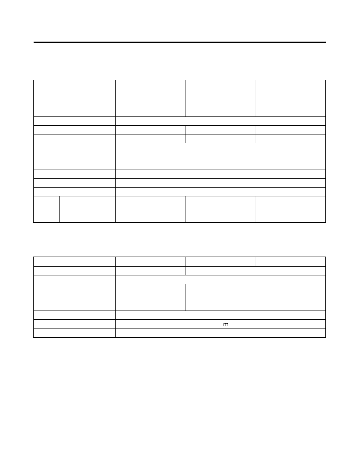
1. Product Specification
1-1. Rated, product specifications
Model Name LRV410TT LRV650TT LRV810TT
Regular Contents 4.7cu.ft 7.5cu.ft 9.9cu.ft
Exterior measurements
(Width X Depth X Height)
Rated Voltage/Frequency 115V / 60Hz
Power Consumption 72W 80W 85W
Weight 47kg 64kg 71kg
Cooling Method Cool Air Automatic Circulation Type
Temperature Control Device MICOM
Outer Case Material Vinyl Coated Metal
Inner Case Material A.B.S Resin
OUT DOOR Indium Thin Oxide Triple Layers Glasses/Aluminium Deco
Insulation Material Poly Urethane Foam (Insulation Foam Gas: Cyclopentane)
Package Exterior
Package
Details
Measurement
(Width X Depth X Height)
Package Weight
595 X 580 X 820 595 X 580 X 1185 595 X 580 X 1475
693 X 717 X 946 693 X 717 X 1296 693 X 717 X 1586
51kg 74kg 81kg
1-2. Component Details
Model Name LRV410TT LRV650TT LRV810TT
Compressor NR45LADG MA53LCDG
Overload Protect 4TM232NFB
P.T.C P220MC P330MC
Heater
Interior Light 12V / 3W / 0.25A
Power Cord (Length) 1.9
Temperature Sensor Heat Reducing Load Resistance Device
•
Interior Heater: Heat up the interior when surrounding temperature is lower than the set temperature.
UPPER: 8W (1EA) UPPER: 8W (2EA)
UPPER: 4W (2EA) UPPER: 5W (2EA)
- 3 -
COMPONENT NAMES AND MOTIONS
2. Component Names and Motions
2-1. Interior
• Interior Light (Interior Ceiling, CASE DISPLAY & BARRIER installed in the lower column) Interior light operates by the
control panel regardless of door opening or closing.
• Interior light uses DC voltage. Please see 1-2, component details.
• 2 or 3 interior lights are installed according to model sizes and light turns on and off by control panel operation button.
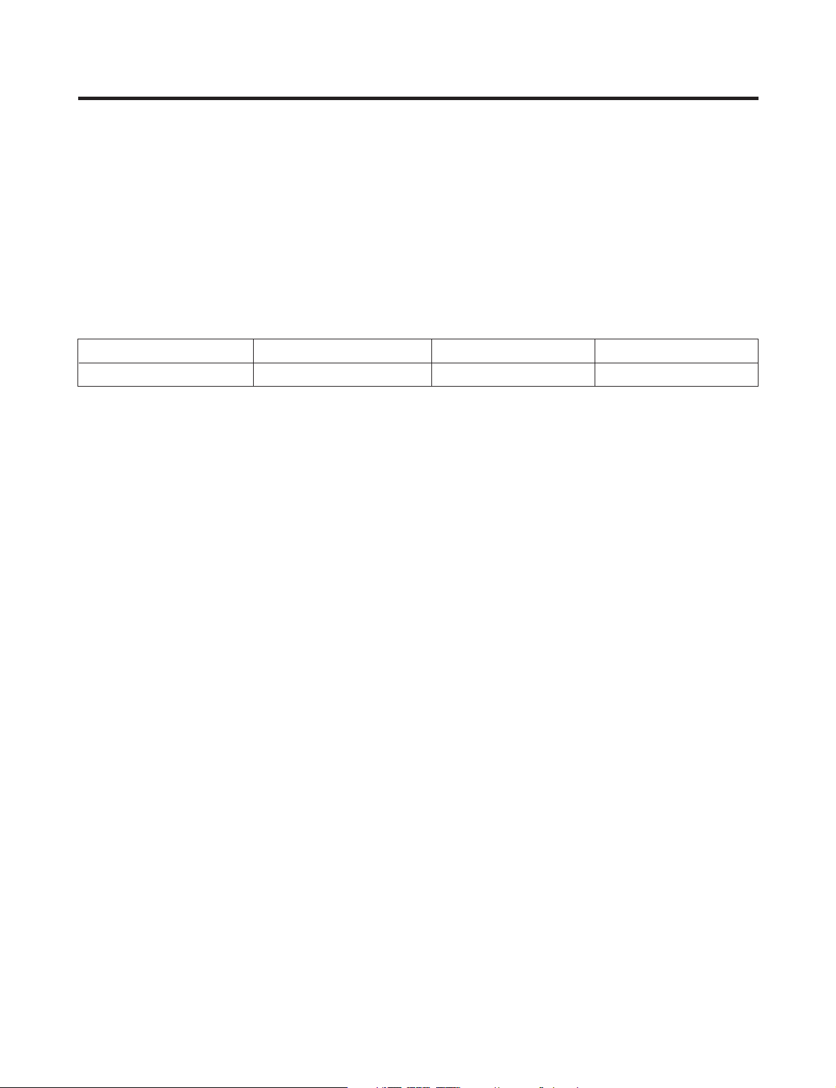
2-2. Wine Rack
• Wine rack detail may vary according to the model types.
• Each rack can hold 8 wine bottles and top rack holds 9 bottles.
Model Name LRV410TT LRV650TT LRV810TT
Standard Capacity 41bottles 65bottles 81bottles
2-3 Others
• Glass Holder
-Hangs wine glasses. (LRV810TT)
• Wine Rack
-Stores leftover wine (tilted). (LRV810TT, LRV650TT)
• Locking Device
-Key is enclosed in the inside of the refrigerator.
• Leg Adjustor (Front & Back, Left & Right, one each)
-Please level the product using the leg adjustor.
- 4 -
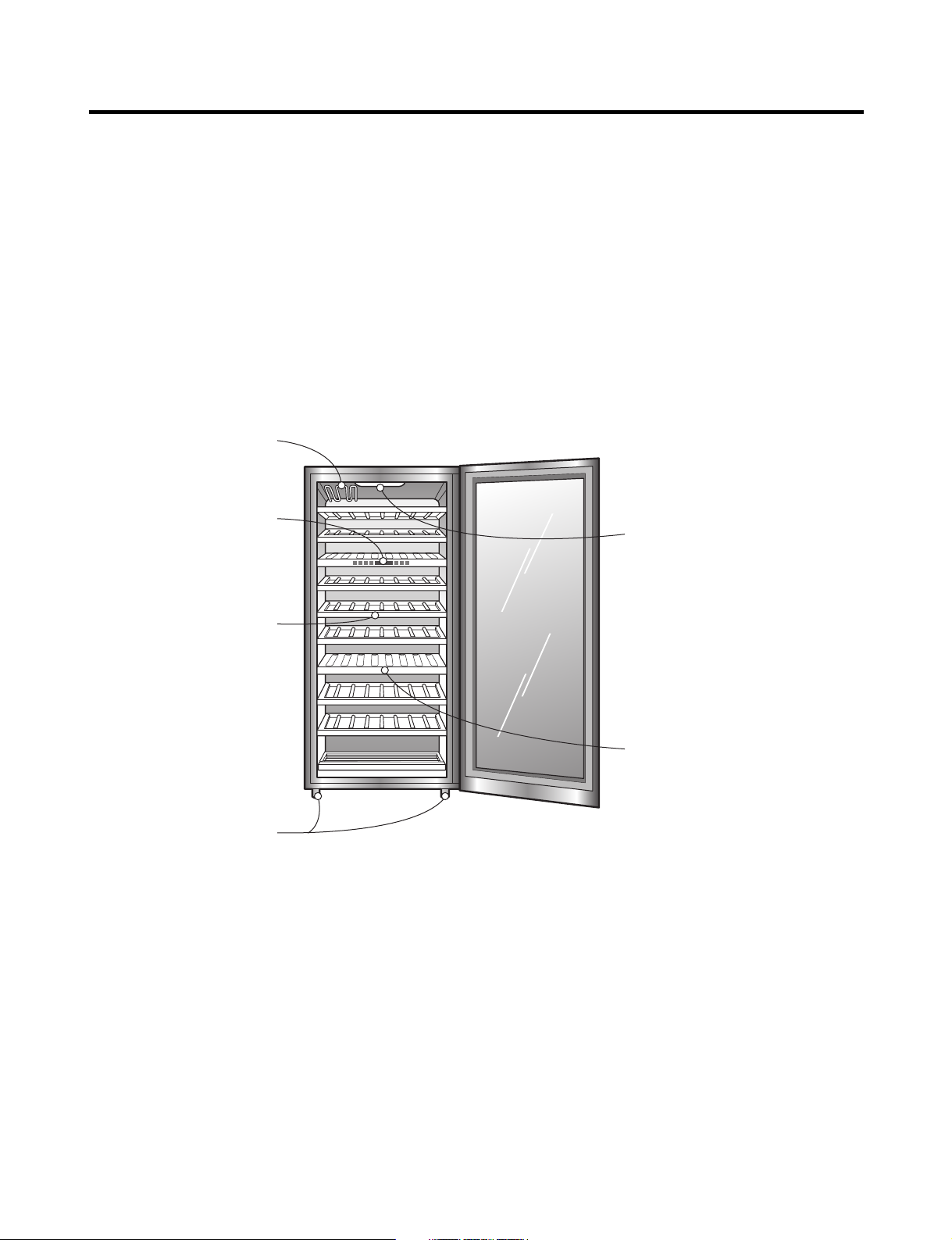
COMPONENT NAMES AND MOTIONS
*Glass tray
Operation panel
Wine shelf
Adjustable support
Can be adjusted when
the fridge is not stable.
Light bulb
• Light bulb inside the wine
fridge can be turned on or
off by pressing the button
on the operation panel.
• Light bulb inside the wine
fridge will automatically
turn off after the door is
open for an hour.
Upper and lower
separation boards
• The upper board is ‘TOP’
and the lower one is
‘BOTTOM’. They can be
used to regulate
temperature.
LRV810TT
- 5 -
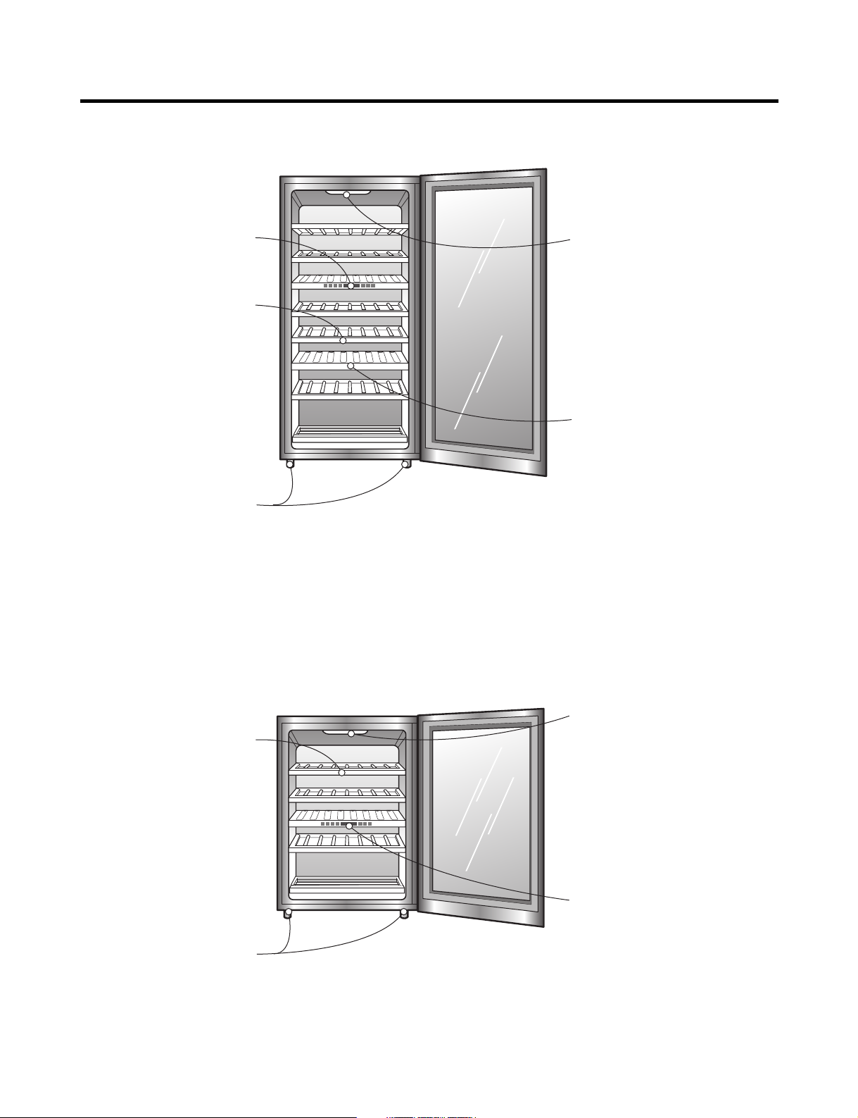
COMPONENT NAMES AND MOTIONS
Operation panel
Wine shelf
Adjustable support
Can be adjusted when
the fridge is not stable.
Light bulb
• Light bulb inside the wine
fridge can be turned on or
off by pressing the button
on the operation panel.
• Light bulb inside the wine
fridge will automatically
turn off after the door is
open for an hour.
Upper and lower
separation boards
• The upper board is ‘TOP’
and the lower one is
‘BOTTOM’. They can be
used to regulate
temperature.
Operation panel
Wine shelf
Adjustable support
Can be adjusted when
the fridge is not stable.
Light bulb
• Light bulb inside the wine
fridge can be turned on or
off by pressing the button
on the operation panel.
• Light bulb inside the wine
fridge will automatically
turn off after the door is
open for an hour.
LRV650TT
LRV410TT
- 6 -
EXTERIOR
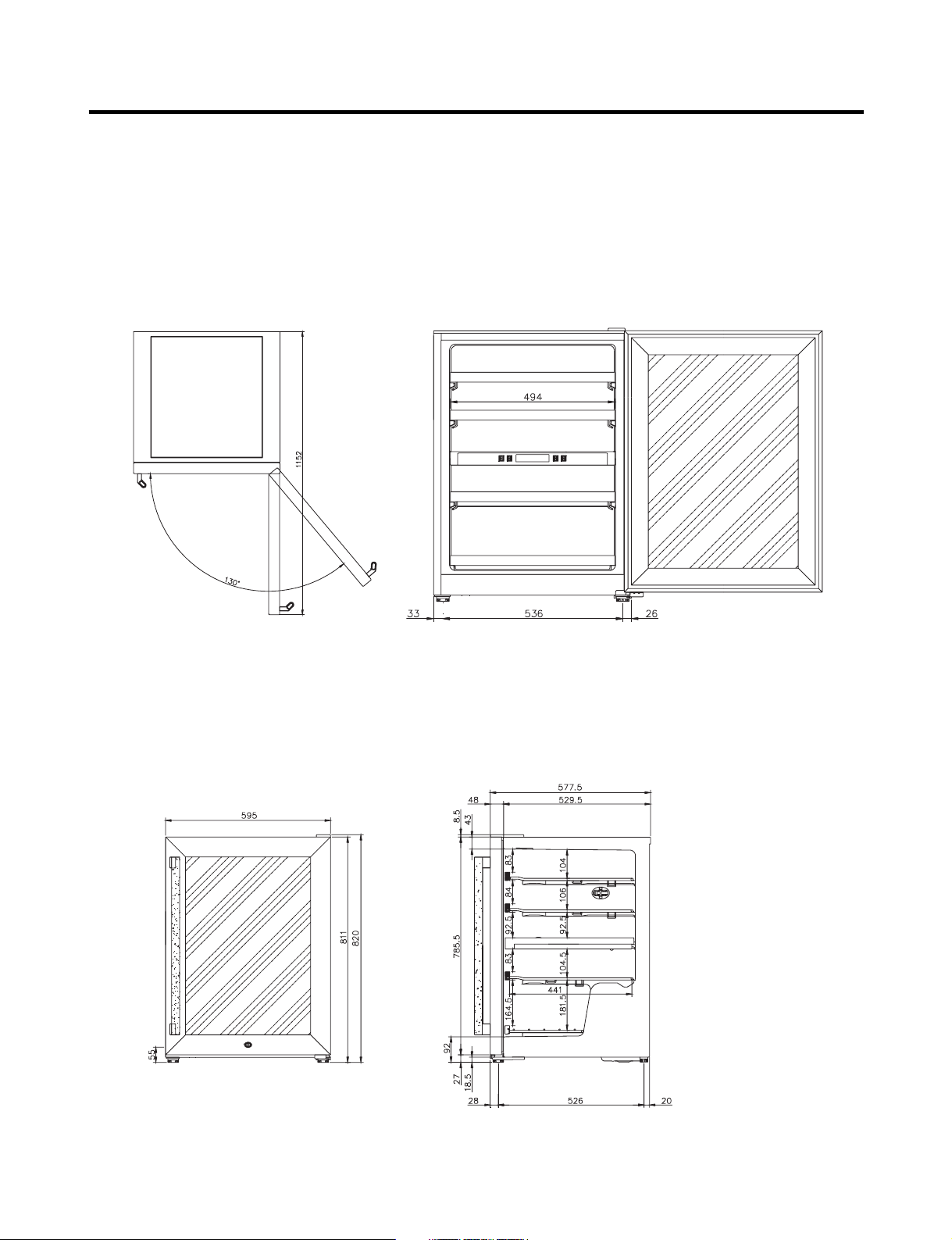
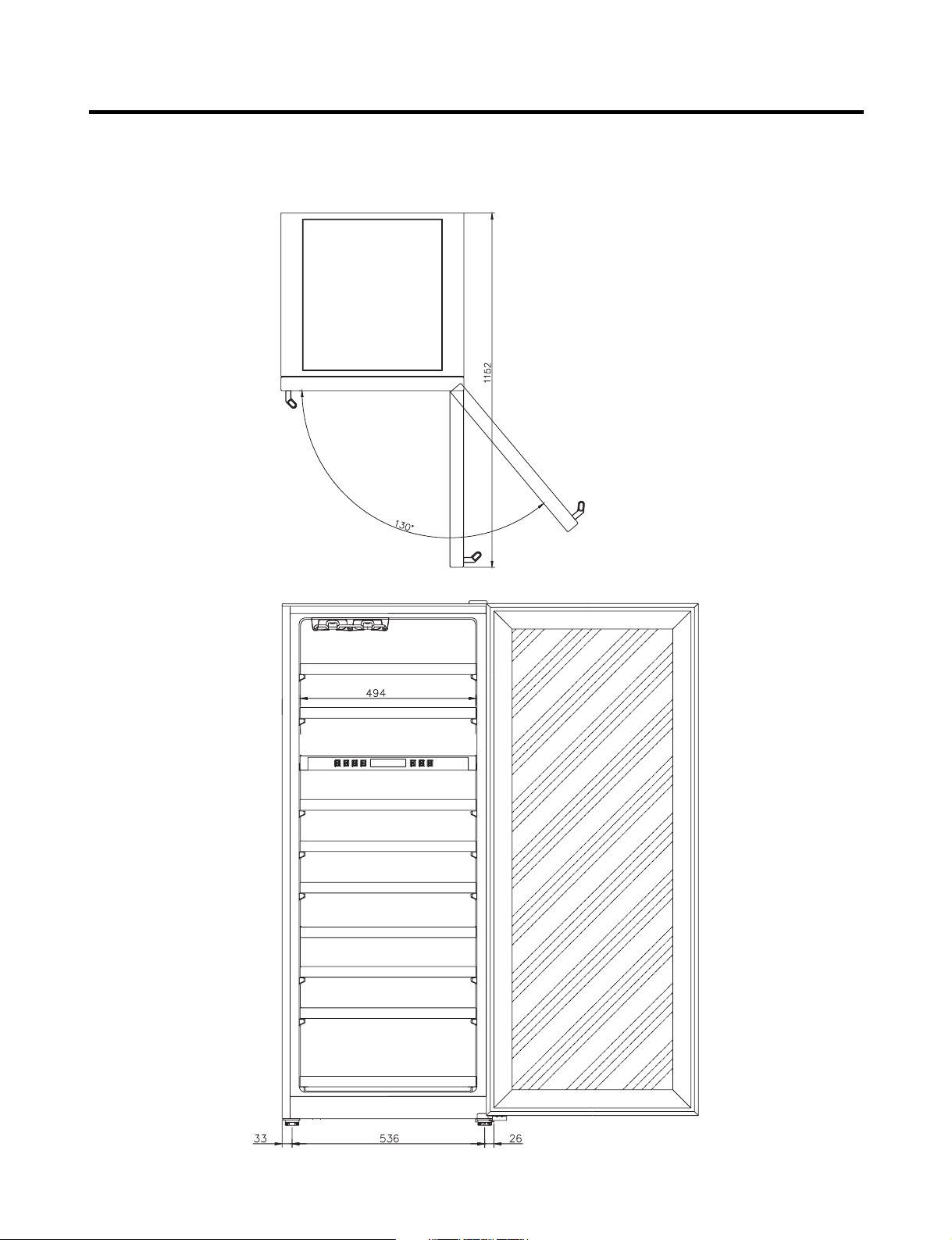
3. Exterior
3-1. Exterior
LRV410TT
- 7 -
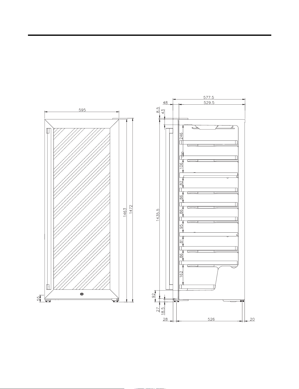
EXTERIOR
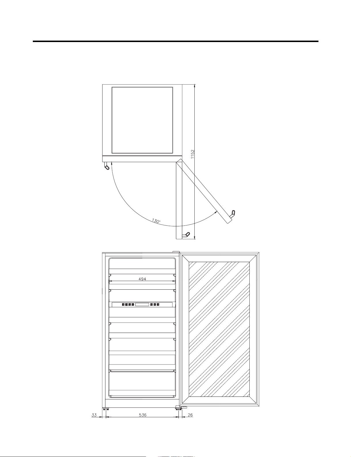
LRV650TT
- 8 -
EXTERIOR
- 9 -
EXTERIOR
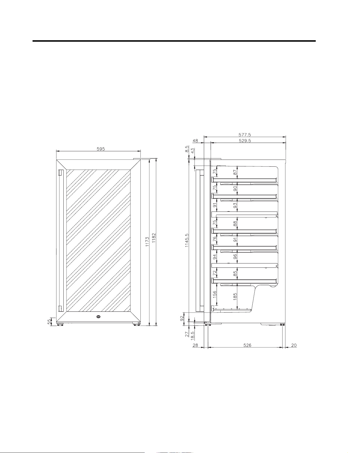
LRV810TT
- 10 -
EXTERIOR
- 11 -
CIRCUIT DIAGRAM
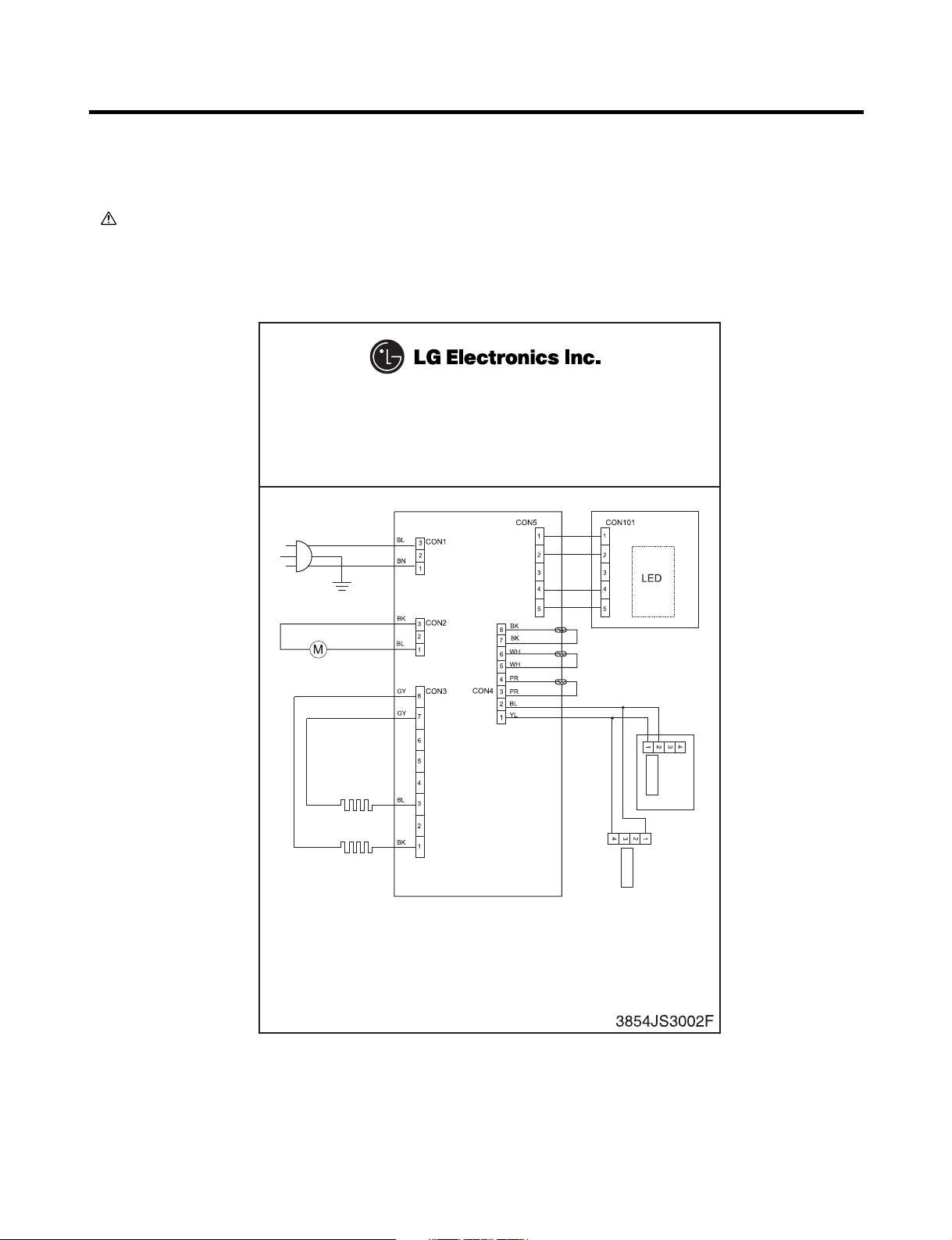
This product is powered by electricity. Once the unit is unplugged,
please wait at least 5 minutes before you plug it back in. If you plug the
power right back in, it will cause a malfunction in the cooling machine.
MODEL: LRV410TT
Power Plug
Compressor
Exterior Temperature Sensor
Interior Temperature Sensor (Top)
Cooling Sensor (Top)
Heater (Top)
Heater (Bottom)
Case Display
Interior Light
Control Panel
BK : BLACK BL :BLUE BO : BROWN OAK BN :BROWN
YL :YELLOW PR :PURPLE GY :GRAY WH : WHITE
Temperature Indicator,
Control Panel
Interior Light
4. Circuit Diagram
4-1. Circuit Diagram
: Indicated component is a safety part. (In case of a replacement, please use a designated part for its function and your
safety.)
LRV410TT
- 12 -
 Loading...