

LG LP-K3023CL Installation Manual
P/No. : 3828A20155A
ENGLISH
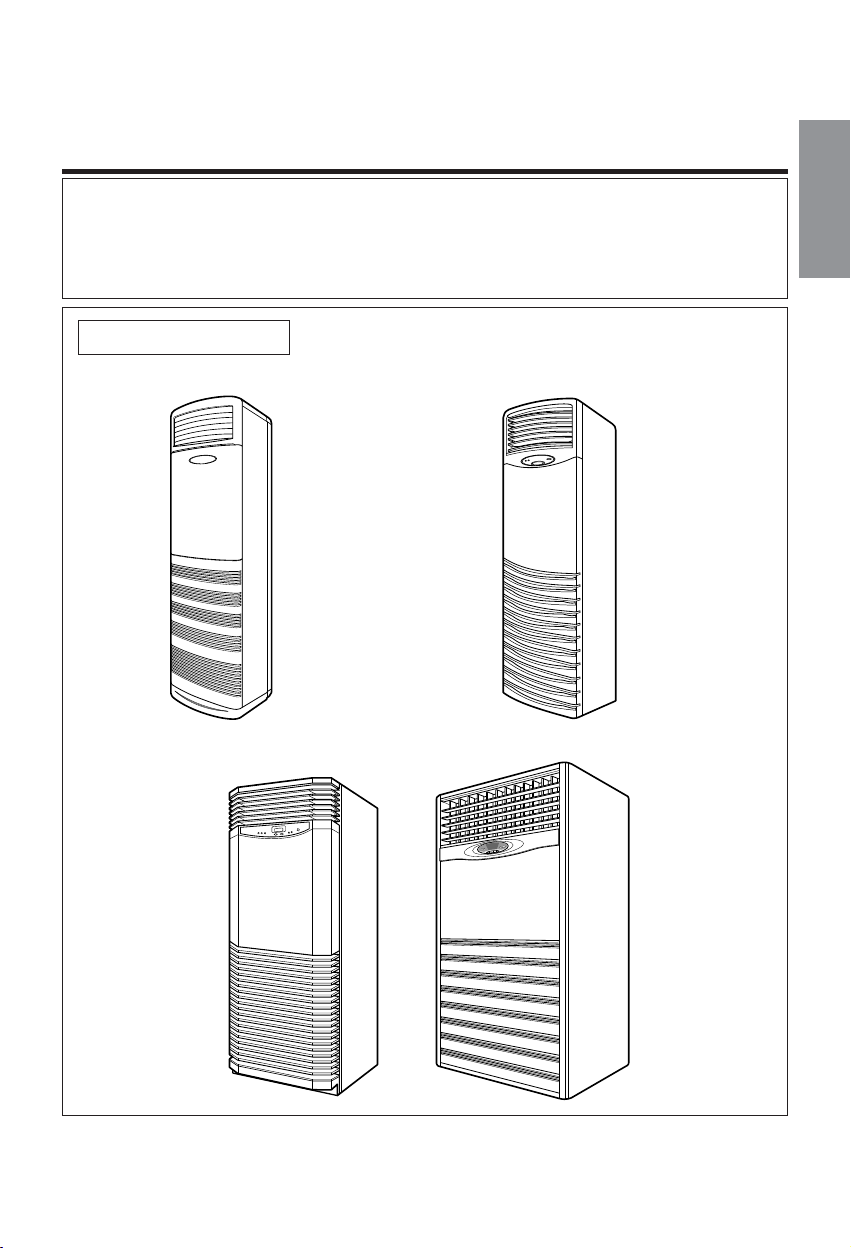
FLOOR STANDING TYPE AIR CONDITIONERS
INSTALLATION INSTRUCTIONS
• Please read this instruction sheet completely before installing the product.
• When the power cable is wanted to replace, replacement work shall be
performed by authorized personnel only.
• Installation work must be performed in accordance with national wiring standards
by authorized personnel only.
Applied Model:
(1) 20K/28K/30K/40K(Btu/h)
(2) 50K(Btu/h)
(3) 80K(Btu/h)

2
Contents
1. Safety precautions
.............................................................................................
3
2. Installation of Indoor, Outdoor Unit
..................................................................
4
1) Selection of the best location
2) Indoor unit installation
3) Outdoor unit installation
4) Refrigerant amount
3. Installation Method
.............................................................................................
6
1) Procedure
2) Preparation of installation parts and tools
4. Piping of Indoor Unit
..........................................................................................
8
1) Preparation of piping
2) Connection of piping
3) Precautions in bending
5. Connecting the Cable to Indoor Unit
................................................................
10
6. Connecting the Cable to tele control Unit
........................................................
11
7. Connecting piping and the Cable to Outdoor Unit
..........................................
12
1) Connecting the piping to the outdoor unit
2) Connecting the cable to the outdoor unit
8. Power Supply and Wiring
..................................................................................
13
1) Power spply
2) Wiring
9. Vacuum Drying of the Connecting Pipes and the Indoor Unit
.......................
14
10. Checking the Drainage and Form the Piping
.................................................
15
1) Checking the Drainage
2) Form the Piping
11. Final Check and Test Run
................................................................................
17
3
ENGLISH
1. Safety precautions
• Please report to or take consent by the supply authority before connection to the system.
• Be sure to read "THE FOLLOWING SHOULD ALWAYS BE OBSERVED FOR SAFETY" before installing
the air conditioner.
• Be sure to observe the cautions specified here as they include important items related to safety.
• The indications and meanings are as follows.
• After reading this manual, be sure to keep it together with the instruction manual in a handy place on the
customer's site.
Could lead to death, serious injury, etc.
Do not install it yourself (customer).
Perform the installation securely referring to the
installation manual.
Install the unit securely in a place which can bear the
weight of the unit.
Perform electrical work according to the installation
manual and be sure to use an exclusive circuit.
Attach the electrical part cover to the indoor unit and the
service panel to the outdoor unit securely.
Be sure to use the part provided or specified parts for
the installation work.
Check that the refrigerant gas due not leak after
installation is completed.
Perform grounding
Do not install the unit in a place where an inflammable
gas leaks.
Perform the drainage/piping work securely according to
the installation manual.
Use the specified wires to connect the indoor and
outdoor units securely and attach the wires firmly to the
terminal board connecting sections so the stress of the
wires is not applied to the sections.
• Incomplete installation could cause injury due to fire, electric shock, the
unit falling or a leakage of water. Consult the dealer from whom you
purchased the unit or special installer.
• Incomplete installation could cause a personal injury due to fire,
electric shock, the unit falling or a leakage of water.
• When installed in an insufficient strong place, the unit could fall
causing injured.
• Incomplete connecting and fixing could cause fire.
• If the capacity of the power circuit is insufficient or there is incomplete
electrical work, it could result in a fire or an electric shock.
• The use of defective parts could cause an injury or leakage of water
due to a fire, electric shock, the unit falling, etc.
Use a vacuum pump or Inert (nitrogen) gas when doing leakage test or air purge.
Do not compress air or Oxygen and Do not use Flammable gases. Otherwise, it may cause fire or explosion.
• There is the risk of death, injury, fire or explosion.
• If gas leaks and accumulates in the area surrounding the
unit, it could cause an explosion.
• If there is a defect in the drainage/piping work, water
could drop from the unit and household goods could be
wet and damaged.
The means for connection to power supply shall be
incorporated in the fixed wiring and have an air gap contact
separation of at least 3mm in all active(phase) conductors.
• This product should be grounded.
• Defective grounding could cause an electric shock.
• If the electrical part cover if the indoor unit and/or the service panel if
the outdoor unit are not attached securely, it could result in a fire or
electric shock due to dust, water, etc.
Could lead to serious injury in particular environments when operated incorrectly.
WARNING
WARNING
CAUTION
CAUTION
20K 5/8" 1/4" 25 15
28K/30K/40K 5/8" 3/8" 30 20
50K 3/4" 3/8" 40 25
80K 1" 5/8" 50 30
4
2. Installation of Indoor, Outdoor unit
5cm
40cm
5cm
100cm
50cm
50cm
50cm
100cm
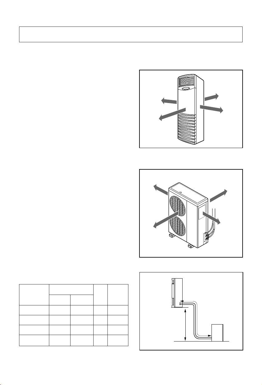
1) Selection of the best location
① Indoor unit
② Outdoor unit
③ Piping length and the elevation
• There should not be any heat source or
steam near the unit.
• There should not be any obstacles to prevent
the air circulation.
• A place where air circulation in the room will
be good.
• A place where drainage can be easily
obtained.
• A place where noise prevention is taken into
consideration.
• Do not install the unit near the door way.
• Ensure the spaces indicated by arrows from
the wall, ceiling, fence, or other obstacles.
• If an awning is built over the unit to prevent
direct sunlight or rain exposure, be careful
that heat radiation from the condenser is not
restricted.
• There should not be any animals or plants
which could be affected by discharged hot air.
• Ensure the space indicated by arrows from
the wall, ceiling, fence, or other obstacles.
PIPE SIZE
MODEL
GAS SIDE LIQUID SIDE
Max.
Length
A (m)
Max.
Elevation
B (m)
A
B
Indoor unit
Outdoor unit
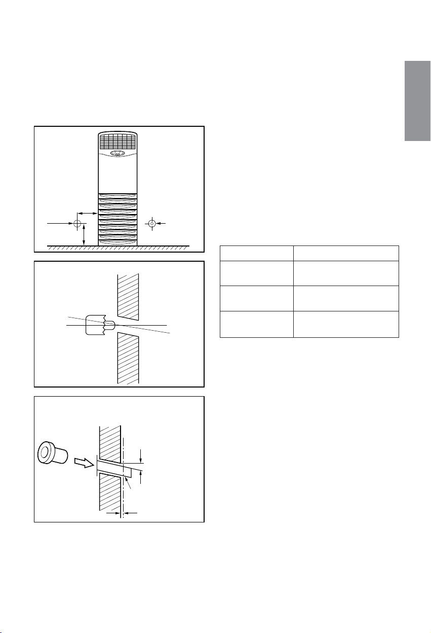
2) Indoor Unit installation
The mounting floor should be strong and
solid enough to prevent it from vibration.
Drill the piping hole with 70mm diameter
hole-core drill at either the right or the left of
indoor unit. The hole should be sightly slant
to the outdoor side.
Insert the plastic tube through the hole.
Cut the extruded outside part of the plastic
tube, if necessary.
3) Outdoor unit Installation
Install the outdoor unit on the concrete or any
solid base securely and horizontally by
securing it with bolts (Ø12mm) and nuts.
If there is any vibration transmitted to the
building, mount the rubber underneath the
outdoor unit.
4) Refrigerant amount
Before shipment, this air conditioner is filled
with the rated amount of refrigerant including
additional amount required for air-purging,
subject to 5m piping length. (The rated
amount of refrigerant is indicated on the
name plate.) But when the piping length
exceeds 5 meters, additional charge is
required according to the following table.
(Unit: g)
Example) 28K/30K
In case of 10m long pipe(one-way), the amount
of refrigerant to be replenished is:
(10 - 5) x 30 = 150g
REFRIGERANT CHARGE
30g per 1m
40g per 1m
50g per 1m
5
ENGLISH
200mm
70mm
70mm
90mm
Wall
Core Drill
Tilt
Cut if necessary
More than 15mm
Wall
Plastic tube
(Bushing)
INSIDE OUTSIDE
MODEL
20K/28K/30K/40K
(Btu/h)
50K
(Btu/h)
80K
(Btu/h)
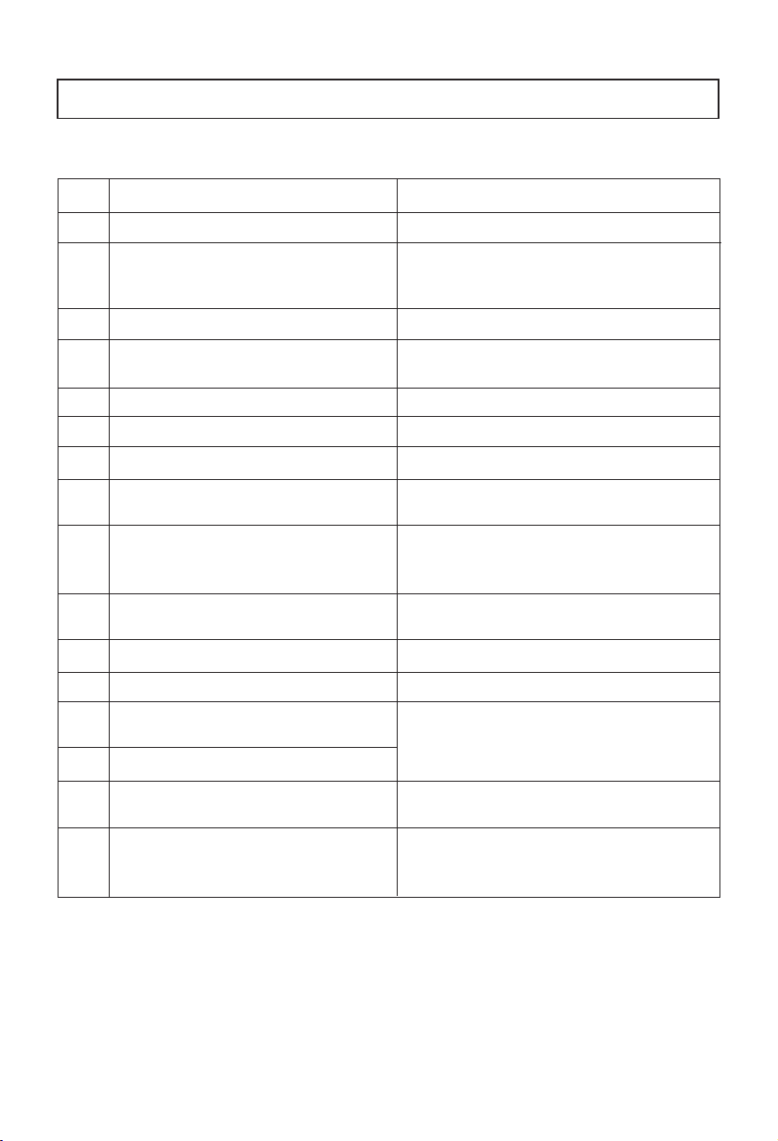
3. Installation Method
No. Installation works Descriptions
1 Preparation of tools and installation parts Preparation of installation
2 Flaring the pipes To insert the flare nuts, mounted on the
connection parts of both indoor and
outdoor unit, onto the copper pipes.
3 Pipe bending To reduce the flow resistance of refrigerant.
4 Connection of installation parts Connection of long piping
(elbows, socket etc)
5 Tighten the flare nut (outdoor) Connecting the pipings of the outdoor unit.
6 Blowing the pipings To remove dust and scale in working.
7 Tighten the flare nut (indoor) Connecting the pipings of the indoor unit.
8 Check a gas-leakage of the connecting
part of the pipings.
9 Vacuum drying of the piping and indoor unit The air which contains moisture and which
remains in the refrigeration cycle may cause a
malfunction on the compressor
10 Open the 3-way (liquid side) and
3-way (gas side) valves.
11 Form the pipings To prevent heat loss and sweat
12 Checking the drainage (indoor unit) To ensure if water flow drain hose of indoor unit.
13 Connecting the cable between outdoor Preparation of the operating
and indoor unit
14 Connecting the main cable to outdoor unit
15 Supply the power to the crankcase heater To prevent the liquid back to the compressor.
(Before the operating the unit) (Heat pump only)
16 Cooling operation
(Use the remote control or display of the
indoor unit)
1) Procedure
6
 Loading...