

LG LP-F8081CL, LP-F8081HL, LP-F8081ZL Service manual

1. Preface
–3–
This service manual provides various service information, containing the mechanical and electrical parts and etc.
This package air conditioner was manufactured and assembled under the strict quality control system.
The refrigerant is charged at the factory. Be sure to read the safety precautions prior to servicing the unit.
1.1 Safety Precautions
¤ When servicing the unit, set the main SWITCH to OFF and remove the POWER SUPPLY cables.
¤Ł Observe the original lead dress. If a short circuit is found, replace all parts which have been overheated or
damaged by the short circuit.
¤Ø After servicing the unit, make an insulation resistance test to protect the customer from being exposed to
shock hazards.
1.2 Features
¤ Design for cooling and heating
¤ŁSuper energy efficiency
¤ØMicom Control
¤ŒWhisper quiet operation
¤ºRemovable air filter
¤ 3 minute delay circuit
¤ 7 hour timer
¤ 3 step speeds for cooling/heating
¤ Auto Restart

1.3 Product Specifications
–4–
POWER SOURCE (ø, V, Hz)
COOLING CAPACITY Btu/h
W
INPUT W
CURRENT A
HEATING CAPACITY Btu/h
(W)
W
(W)
INPUT W
(W)
CURRENT A
(A)
MAKER
TYPE
COMPRESSOR MODEL
INPUT W
CURRENT A
CAPACITY Kcal/h
NOISE INDOOR dB(A)
LEVEL(1m) OUTDOOR
AIR INDOOR CMM
VOLUME OUTDOOR
REFRIGERANT R-22 Kg
HEAT INDOOR R/C/FPI
EXCHANGER OUTDOOR R/C/FPI
FAN INDOOR TYPE
OUTDOOR
ROOM TEMPERATURE CONTROL
NET INDOOR Kg
WEIGHT OUTDOOR
DIMENSIONS INDOOR mm
(W × H × D) OUTDOOR
SVC LIQUID Inch
VALVE GAS (mm)
3,380 – 415,50 3,380 – 415,50
71,400 71,400
20,927 20,927
6,900 7,000
12.0 13.0
–
74,000
(8,000)
–
21,680
(8,000)
–
6,500
(8,000)
–
12.5
(12.0)
COPELAND COPELAND
SCROLL SCROLL
ZR94KC – TFD ZR94KC – TFD
6,990 6,990
13.6 13.6
19,732 19,732
56 56
65 65
35 35
104 104
5.9 7.2
3/33/17 3/33/17
2/18/17 2/18/17
SIROCO SIROCO
PROPELLER PROPELLER
MICOM CONTROL MICOM CONTROL
132 132
150 150
1,050 ×1,880 ×495 1,050 ×1,880 ×495
1,000
×
965 ×370 1,000 ×965 ×370
5/8 5/8
1 1
MODEL
LP-F8081CL
LP-F8081HL
LP-F8081ZL
(Including Electric
heater)

–5–
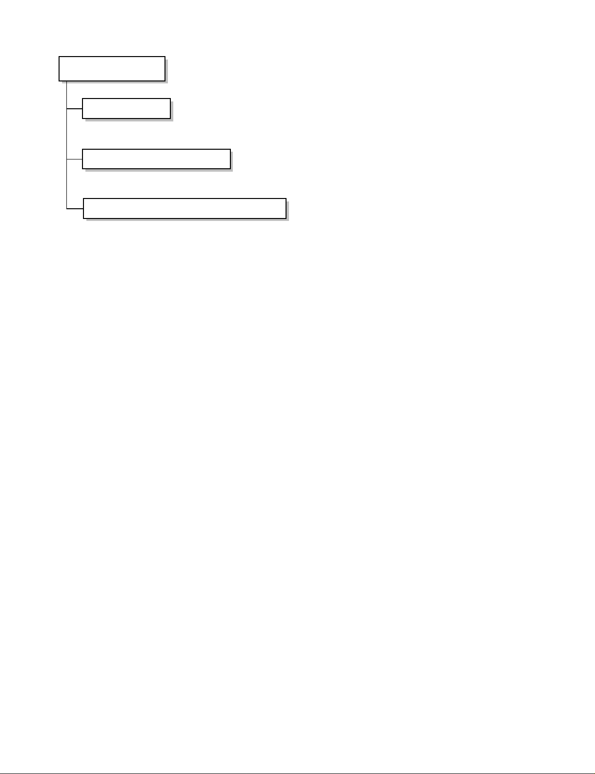
1.4 Functions
Indoor Unit
Power Switch ON/OFF
Operation Mode Control
Sensing the room temperature
Controlling the room temperature
Starting Current Control
Sensing Heat Exchanger Temperature
Timer Delay Safety Control
Indoor Fan Speed Control
Operation Indication lamps
Temperature Setting
Airflow Direction Control
Room temperature Display
Timer Control
• Cooling, Soft Dry, Auto, Fan ➔ Cooling Model •
Cooling, Heating, Soft Dry, Fan➔ Heat Pump Model
• Room temperature sensor (Thermistor)
• Maintains the room temperature in accordance with the setting temperature.
• Indoor fan is delayed for 3 sec at the starting.
• Heat exchanger temperature sensor (Thermistor)
• Restarting is inhibited for approx. 3 minutes.
• High, Low, Duct
• Up : up to 30°C
• Down : down to 16°C
• Airflow direction Manual control
• Low, 10° ~ 35°C, Hi
• Off Timer (1, 2, 3....7 hour)
–6–
Outdoor Unit
Deice Control
Outdoor Fan Speed Control
Sensing Heat Exchanger Temperature
• De-ice PCB
• One speed
• Heat exchanger temperature sensor (Thermistor)

2. Dimensions
–7–
Indoor Unit
Outdoor Unit
268568990
1890
1051
496
75
130 121
75
193
951
36
36
60
345
93.8
131
36
75
525
109.5
58.5
145.8
93.8
Air Outlet
Vent
Air Inlet
Vent
Window
Display
Earth
Screw
700
650
963
930
582
185
125
546
1245
700
50
260
95 80
Air Outlet Vent
Air Inlet Vent
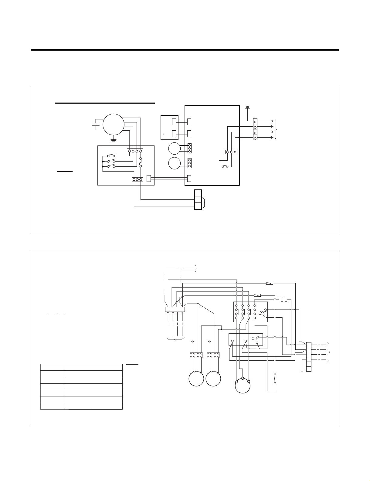
3. Wiring Diagram
Indoor & Outdoor Unit Circuit Diagram
(1) LD-F8081CL
–8–
INDOOR UNIT CIRCUIT DIAGRAM
OR
BK
BL
RD
BR
YL
RY3
CN2
CN3
DISPLAY
PCB ASM
CN1
RD
GN/YL
CONNECT TO
OUTDOOR UNIT
WH
BK
BK
GN/YL
BL
BR
YL
BL
CONNECT TO CONTACT "R" "N" OF
OUTDOOR TERMINAL BLOCK "Tmo1"
NOTE
BL
BK
BR
OR
RD
WH
YL
GN/YL
BLUE
BLACK
BROWN
ORANGE
RED
WHITE
YELLOW
GREEN/YELLOW
:
:
:
:
:
:
:
:
RY3
1
MAIN PCB ASM
RY2
FUSE
(10A)
RY1
SUB PCB ASM
CAPACITOR
INDOOR
FAN MOTOR
ROOM
TH
EVA
TH
2 3 4
3
2
1
FIELD WIRING
NOTE
1. This product is 3ø,4W,380-415V,50Hz.
2. "Check List" before test run.
1st: Reconfirm the wiring connecting
of compressor, outdoor unit motor.
2nd: Fasten the screw of "Terminal Block
Tmo1,2" once more.
Tmo1,2
52C
51C
63H
CH
FMo1,2
Co1,2
TERMINAL BLOCK
MAGNETIC CONTACTOR
EOCR(COMP.)
HIGH PRESSURE SWITCH
CRANKCASE HEATER
OUTDOOR FAN MOTOR
RUN CAPACITOR FOR FAN(OUTDOOR)
NOTE
BL
BLUE
:
BK
BLACK
:
BR
BROWN
:
OR
ORANGE
:
RD
RED
:
WH
WHITE
:
YL
YELLOW
:
GN
GREEN
:
GN/YL
GREEN/YELLOW
:
BK
Tmo1
R S T N
3Ø, 4W
380-415V, 50Hz
POWER SUPPLY
CONNECT TO
INDOOR UNIT
WH
WH
OR
OR
BK
Co1
Co2
YLBRORBKYLBROR
FMo2FMo1
RD
WH
52C
BK
BK
L1 L2
WH
BK
T1
1 3 5 31
2 4 6 32
WH
T3
COMP
FUSE(5A)
B
51C
Ta
Tb
Tc
RD
T2
FUSE(5A)
WH
BK
A
BK
BK
RD
WH
63H
CH
BK
BK
WH
GN/YL
BK
CONNECT TO
INDOOR UNIT
BR
1
BL
2
BK
3
GN/YL
4
5
6
Tmo2

–9–
(2) LD-F8081HL/ZL
INDOOR UNIT CIRCUIT DIAGRAM
CAPACITOR
BR
OR
BK
BL
RD
YL
INDOOR
FAN MOTOR
RY3
RY2
RY1
SUB PCB ASM
FUSE
(10A)
DISPLAY
PCB ASM
MAIN PCB ASM
CN1
CN2
ROOM
TH
EVA
TH
CN3
Tmi
YL
BL
3
2
1
CONNECT TO CONTACT "T" "N" OF
OUTDOOR TERMINAL BLOCK "A"
Ry3
Ry6
Ry7
BKBKBK
TF
TF
BK
BL
BK
BKWHRD
POWER SUPPLY
3Ø 380~415V
50Hz
L1
L2
L3
a
T1
T2
T3
b
EH
1 2 3
4 5 6
5
4
Tmi
CONNECT TO OUTDOOR
(HOUSING ASM)
TP
Option part
DEF TH
EH
EVA TH
ROOM TH
Ry3
Ry6
Ry7
THi
Tmi
TP
TF
TERMINAL BLOCK(INDOOR)
BIMETAL SWITCH FOR HEATER
THERMAL FUSE
RELAY FOR COMP
RELAY FOR HEATER
RELAY FOR HEATING
THERMISTOR FOR INDOOR TEMP
THERMISTER FOR DISCHARGE AIR
ELECTRIC HEATER
THERMISTER FOR EVA TEMP.
THERMISTER FOR EVA INDOOR TEMP
NOTE
BK:BLACK
BL:BLUE
BR:BROWN
YL :YELLOW
WH:WHITE
OUTDOOR UNIT WIRING DIAGRAM
F2
RD RD RD
TM
R S T N
POWER SUPPLY
3ø,380-415V,50Hz
TERMINAL(4P)
CRANKCASE HEATER
CH
FUSE (250V, 5A)
F1,2
RUN CAPACITOR FOR FMo
Co
OUTDOOR FAN MOTOR
FMo
GN/YL
YLBRORBKYLBROR
YLBRORBKYLBROR
FMo
49FMo
63H2
BK
F2
BK
BK
WH
RD
RD
63H1
52C
BK
BK
FMo
49FMo
D.P
C TH
20SV
49FMo
BKWHRD
L1
COMP
DEICER PCB
THERMISTOR FOR PIPE TEMP.(OUTDOOR)
REVERSING COIL
INERNAL T.P FOR FMo
BK
BK
1 3 5 31 A
2 4 6 32 B
L3
L2
BK
R
A B
YL
BK
52F1
63H1
63H2
49C
WH
3.P.D
S T
WH WH
WH
BK
WH
BK
20SV
RELAY FOR FMo
HIGH PRESSURE SWITCH
HIGH PRESSURE SWITCH FOR HEATING
INTERNAL O.L.P FOR COMP.
BL
BL
BK
NOTE
BL
BK
BR
OR
BK
D.P
52F1
1 2
3 4
5 6
7 8
OR
BLUE
:
BLACK
:
BROWN
:
ORANGE
:
TM
52C
3.P.D
1
2
3
4
5
6
C TH
BL
BR
BL
BR
BL
GN/YL
NC
NO NC NO
YL
RD
RED
:
WH
WHITE
:
YL
YELLOW
:
GN/YL : GREEN/YELLOW
MAIN TERMINAL BLOCK
MAGNETIC CONTACTOR
3 PHASE DETECTOR

– 10 –
4. OPERATION DETAILS
(1) The function of main control
1. Time Delay Safety Control
• 3min
...
The compressor is ceased for 3 minutes to balance the pressure in the refrigeration cycle.
(Protection of compressor)
• 3sec
...
The indoor fan is ceased for 1~3 seconds to prevent relay noise.
(Protection of fan relay and micro chip)
• 1min
...
The 4-way valve is ceased for 30 sec. to prevent the refrigerant-gas abnormal noise when the Heating
operation is OFF or switched to the other operation mode.
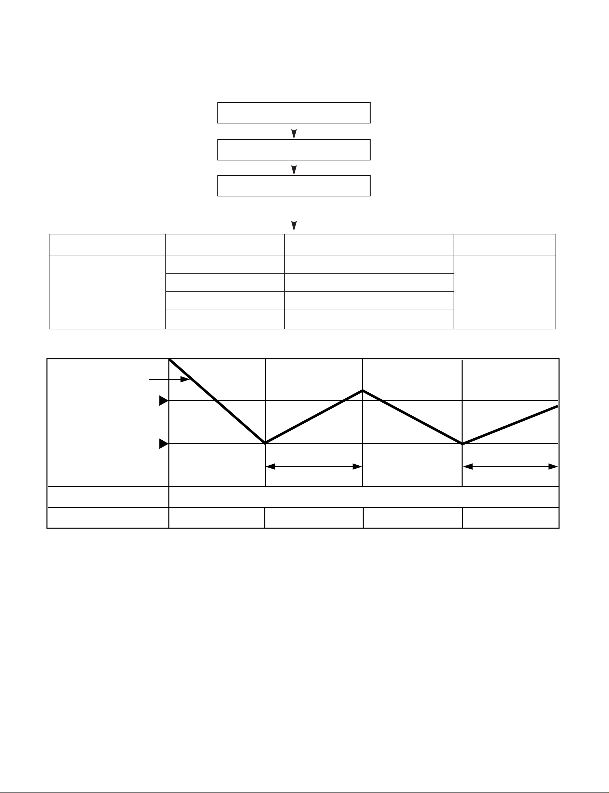
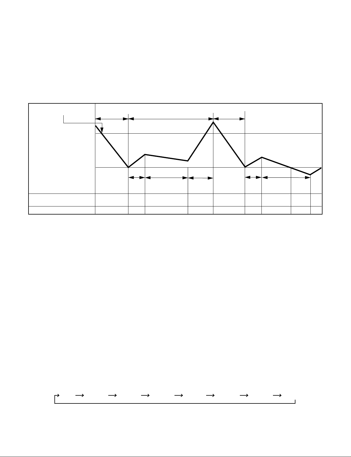
2. Cooling Mode Operation
• When selecting the Cooling( ) Mode Operation, the unit will operate according to the setting by the
controller and the operation diagram is as following
Intake Air temp.
Setting Temp. +1°C
(Compressor ON)
Setting Temp. -1°C
(Compressor OFF)
Indoor Fan Speed
Selecting
fan speed
Selecting
fan speed
Selecting
fan speed
Selecting
fan speed
Selecting
fan speed
3 minutes 3 minutes
Compressor ON OFF ON OFF ON
– 11 –
3. Auto Operation (Cooling Model only)
ƒUThe operation procedure is as following.
ƒƒUU
Auto Operation for Cooling
Press Start/Stop Button
Select Auto Operation Mode
Check the Room temperature
Operation Condition Intake-air Temperature Setting temperature Fan speed
Over 26°C 25°C
Over 24°C~below 25.5°C Intake air -1.0°C
Over 22°C~below 23.5°C Intake air -0.5°C
below 21.5°C Intake air Temperature(18°C, MAX)
When Switch to
Auto Operation
Controlled
by Fuzzy logic
Intake Air Temp.
Indoor Fan Speed
Compressor ON OFF
Fuzzy Speed
ON OFF
Setting Temp. +1°C
(Compressor ON)
Setting Temp. -1°C
(Compressor OFF)
3 minutes 3 minutes
– 12 –
4. Heating Mode Operation
The unit will operate according to the setting by the remote controller and the operation diagram is shown as
following.
Intake Air Temp.
Setting Temp.
(Compressor ON)
Setting Temp. -1°C
Indoor Fan Speed
Compressor
Electric Heater(Option)
ON
ON
OFF ON OFF
OFFOFF ON OFF
OFF
LOW
Hot
Start
minimum
10sec.
minimum
1min
minimum
10sec.
OFF
A A
OFFLOW LOW
Setting Temp. +1°C
(Compressor OFF)
Selecting
fan speed
Selecting
fan speed
• A point: The indoor pipe temperature to be less then 35°C or Discharge air Temperature to be less than 29°C.
The indoor fan operates for minimum 10sec. even if the indoor pipe temperature falls lower than35°C
or the discharge air Temperature falls lower than 29°C.
Low(V)Stop(VI)
39˚C
Discharge Air Temp.
Indoor Pipe Temp.
34˚C
28˚C
26˚C
Selecting Fan Speed(IV)
Low(II)Stop(I)
(Hot-Start Operating)
Heating Start
(Hot-Start Release Point)
Selecting Fan Speed(III)
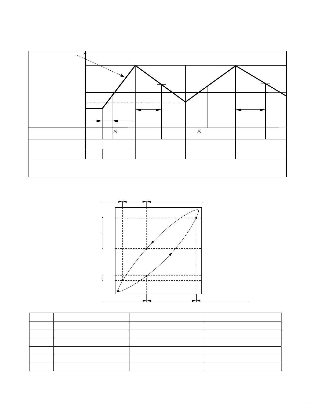
¡ During heating operation, the operating procedure of the indoor fan is as the following.
Step Indoor fan speed Pipe temp. Air discharge temp.
¥ Off ≤28°C(Hot start operating) –
¥– Low ≥28°C <39°C
¥† Selecting speed ≥28°C ≥39°C
¥‡ Selecting speed ≥28°C >34°C
¥· Low ≥26°C ≤34°C
¥ Off ≤26°C –

– 13 –
5. Hot-Start Control
• The indoor fan stops until the evaporator piping temperature will be reached to 28°C.
• During heating operation, if piping temperatures fall below 26°C fan stops.
• The operation diagram is as following.
6. Defrost Control
• Defrost operation is controlled by timer and sensing temperature of outdoor pipe.
• The first defrost starts only when the outdoor pipe temperature falls below -6°C after 45 minutes passed from
starting of heating operation and more than.
• Defrost ends after 10 minutes pass from starting of defrost operation or when the outdoor pipe temperature rises
over 12°C even if before 10 minutes.
• The second defrost starts only when the outdoor pipe temperature falls below -6°C after 45 minutes pass from
ending of the first defrost and more than.
INDOOR PIPE
TEMP.
INDOOR FAN
SPEED
Selecting
fan speed
OFF OFFLOW
1min
Maximum
COMPRESSOR ON
28°C
26°C
More than 45 minutes of
heating operation
Outdoor Pipe Temp.
Indoor Fan
Compressor
4-Way Valve
ON
ON
ON
ON
OFF
ON
OFF
HOT-
START
ON
ON OFF OFFON
12°C
(Defrost OFF)
-6°C
(Defrost ON)
Within
10minutes
Defrost
Defrost
More than 45 minutes of
heating operation
Less than 5 minutes
9. Child Lock function
This function is to operate Air conditioner only by Remocon.
The procedure is as the following
1st: Press the 2 buttons of the temperature control simultaneously, to raise-to lower on the Display Panel of the
product for more 3 seconds.
2nd: The buzzer sounds and then the window of Display Panel shows
LLOOCC
(LOC) mark.
3rd: To release this function, the reverse again the operating procedure could be done.
¡ During this function is operating, any buttons of Display Panel don't work. But it is possible to operate with
Remote controller.
10. Off Timer Function
This function is to set the time of stopping the unit operation.
The procedure is as the following.
1st: Press the timer set button on the Remocon.
2nd:
The buzzer sounds and then the display window shows the Off-Time to be set as 1:00¡
...
¡ 7:00 ¡ 0:00.
- The Off-Time is shifted as the following by each press.
- If you select '0:00', the Off-Timer function will be cancelled.
- During Off-Timer Operation, if you repress the timer set button, the rest time will be displayed.
– 14 –
8. Protection of the evaporator pipe from frosting
• Compressor and outdoor fan stop when indoor pipe temperature is below -2°C and restart at the pipe temperature
is above 12°C.
7. Soft Dry Operation Mode
• During Soft Dry Operation, the compressor ON temperature is the setting temperature plus 2°C, the compressor OFF temperature is the setting temperature minus 1°C.
• When the room temperature rises over the compressor ON temperature, the operation mode is switched to the
Cooling mode.
• When the room temperature falls between the compressor ON temperature and OFF temperature, the operation mode is switched to the Soft Dry Operation.
• The operation diagram is shown below.
Intake Air Temp.
Indoor Fan Speed
LOW
Selecting
fan speed
Selecting
fan speed
LOW LOW LOW LOW
Compressor OFFON ONON OFF OFF ON
LOW
OFF
Setting Temp. +2°C
(Compressor ON)
Setting Temp. -1°C
(Compresso OFF)
Operation
Cooling
Cooling
operation
Dry operation
3 min. 3 min.
10 min.
maximum
7 min.
maximum
10 min.
1:00 2:00 3:00 4:00 5:00 6:00 7:00 0:00

11. Alarm mode display / only displayed while operating.
CCHH 00
: The sensor for sensing room temperature is open or short.
CCHH 11
: The sensor for sensing piping temperature of evaporator is open or short.
12. Function for test operation.
This function shall be operated while the set not operating and start while set temperature set button(▼) down
and start/stop buttons pressing continuously for 3 seconds.
If you press start/stop button continuously for 3 seconds while set temp down button pressing once more test
operation and the set shall be stopped.
After test operation operating and 18 minutes, test operation and the set shall be stopped.
If you press start/stop button while test operation operating, test operation shall be stopped and the set shall
start.
When test operation operating, the display of
8888::8888
shall be shifted to tESt
4-way valve is always off when test operation.
Fan speed is high, air purifying system and auto air flow operations are off when test operation.
Regardless of outside temperature, the set operates when test operation.
All but start/stop and air purifying system buttons cannot be set.
13. Function of changing set temperature when re-operation after stop.
Heating operation is set to the previous set temperature when re-operation after stop. Cooling operation is set
to the previous set temperature when re-operation with start/stop button.
1.Operation mode.
Cooling/soft dry mode → Cooling mode
Heating mode → Heating mode
2. Setting the set temperature when cooling operation.
Room temperature > Set temperature: to be set to the previous set temperature.
Room temperature ≤ Set temperature
a) Room temperature ≥ 26°C: to be set to 24°C
b) 22°C ≤ Room temperature ≤ 25°C: to be set to 21°C
c) Room temperature ≤ 21°C:to be set to -1°C less than room temperature.
3. Setting the set temperature when heating operation.
Set the previous set temperature when stopped.
14. Auto Restart
In case the power comes on again a power failure, Auto Restarting Operation is the function to operate procedures automatically to the previous operating conditions.
– 15 –
5-1.
Installation of Indoor, Outdoor unit
1) Selection of the best location
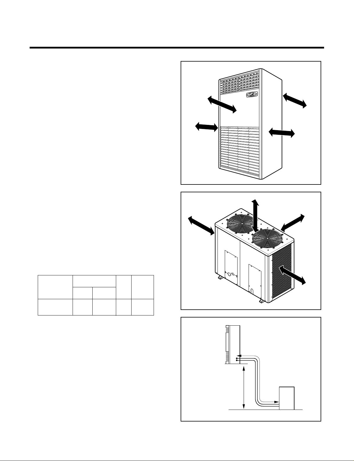
➀ Indoor unit
• There should not be any heat source or steam
near the unit.
• There should not be any obstacles to prevent the
air circulation.
• A place where air circulation in the room will be
good.
• A place where drainage can be easily obtained.
• A place where noise prevention is taken into con-
sideration.
• Do not install the unit near the door way.
• Ensure the spaces indicated by arrows from the
wall, ceiling, fence, or other obstacles.
➁ Outdoor unit
• If an awning is built over the unit to prevent direct
sunlight or rain exposure, be careful that heat
radiation from the condenser is not restricted.
• There should not be any animals or plants which
could be affected by discharged hot air.
• Ensure the space indicated by arrows from the
wall, ceiling, fence, or other obstacles.
–16–
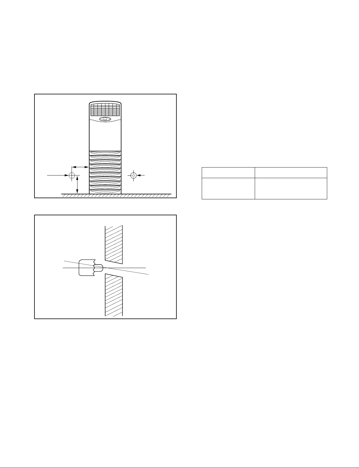
5. Installation
5cm
A
B
Indoor unit
Outdoor unit
50cm
50cm
50cm
150cm
5cm
40cm
100cm
➂ Piping length and the elevation
1" 5/8" 50 35
80K
(Btu/h)
PIPE SIZE
MODEL
GAS SIDE LIQUID SIDE
Max.
Length
A (m)
Max.
Elevation
B (m)
–17–
2) Indoor Unit installation
➀ The mounting floor should be strong and solid
enough to prevent it from vibration.
➁ Drill the piping hole with 70mm diameter hole-
core drill at either the right or the left of indoor
unit. The hole should be sightly slant to the outdoor side.
3) Outdoor unit Installation
➀ Install the outdoor unit on the concrete or any
solid base securely and horizontally.
➁ If there is any vibration transmitted to the build-
ing, mount the rubber underneath the outdoor
unit.
4) Refrigerant amount
Before shipment, this air conditioner is filled with
the rated amount of refrigerant including additional
amount required for air-purging, subject to 5m piping length. (The rated amount of refrigerant is indicated on the name plate.) But when the piping
length exceeds 5 meters, additional charge is
required according to the following table.
(Unit: g)
Example) 72K~80K
In case of 10m long pipe(one-way), the amount of
refrigerant to be replenished is:
(10 - 5) × 80 = 400g
200mm
70mm
70mm
90mm
Wall
Core Drill
MODEL
80K
REFRIGERANT CHARGE
80 per 1m

–18–
5-2. Installation Method
1) Procedure
No. Installation works Descriptions
1 Preparation of tools and installation parts Preparation of installation
2 Flaring the pipes To insert the flare nuts, mounted on the
connection parts of both indoor and
outdoor unit, onto the copper pipes.
3 Pipe bending To reduce the flow resistance of refrigerant.
4 Connection of installation parts Connection of long piping
(elbows, socket etc)
5 Tighten the flare nut (outdoor) Connecting the pipings of the outdoor unit.
6 Blowing the pipings To remove dust and scale in working.
7 Tighten the flare nut (indoor) Connecting the pipings of the indoor unit.
8 Check a gas-leakage of the connecting
part of the pipings.
9 Air purging of the piping and indoor unit The air which contains moisture and which
remains in the refrigeration cycle may cause a malfunction on the
compressor
10 Open the 3-way (liquid side) and
3-way (gas side) valves.
1 1 Form the pipings To prevent heat loss and sweat
12 Checking the drainage (indoor unit) To ensure if water flow drain hose of indoor unit.
13 Connecting the cable between outdoor Preparation of the operating
and indoor unit
14 Connecting the main cable to outdoor unit
15 Supply the power to the crankcase heater To prevent the liquid back to the compressor.
(Before the operating the unit) (Heat pump only)
16 Cooling operation
(Use the remote control or display of the
indoor unit)

–19–
2) Preparation of installation parts and tools
No. Installation Parts, Tools Use
1 Pipe cutter (MAX 35mm Copper pipe) Cutting the pipings
2 Remear Remove burrs from cut edges of pipes.
3 Wrench (H5, H4 hexagonal wrench) To open the service valve
4 Pipe bender Bending the pipings
5 Leak detector Check a gas-leakage of connecting part
of the pipings
6 Manifold gauge To measure the pressure, to charge the refrigerant
7 Charge-nipple To connect the bombe
8 Vacuum pump To remove the air in the pipe.
9 Charge cylinder balance To measure the refrigerant amount
10 Bombe (Freon-22) Gas charge
Air purge
Cleaning the pipe
11 Spanner To tighten the connecting parts of the pipings
12 Monkey spanner
13 Driver( , )
14 Benchi (150mm) Cutting the wires
15 Tapeline To measure the length
16 Core drill To make holes through the concrete wall and blocks
17 Voltmeter, Amperemeter, Clampmeter To measure the current and voltage
18 Insulation resistance tester To measure the insulation resistance
19 Glass thermometer
To measure the intake and outlet air temperature of the indoor unit
20 Copper tubes To use the connecting pipings
21 Insulation material To cover the connecting pipings
22 Tape To finish the connecting pipings
23 Electrical Leakage Breaker To shut off the main power
24 Cable To connect the cable from outdoor unit to indoor unit
27 Drain hose sockets, elbows To remote the condensing water
–20–
➀ Cut the pipes and the cable
• Use the accessory piping kit or the pipes
purchased locally.
• Measure the distance between the indoor and
the outdoor unit.
• Cut the pipes a little longer than measured
distance.
• Cut the cable 1.5m longer than the pipe length.
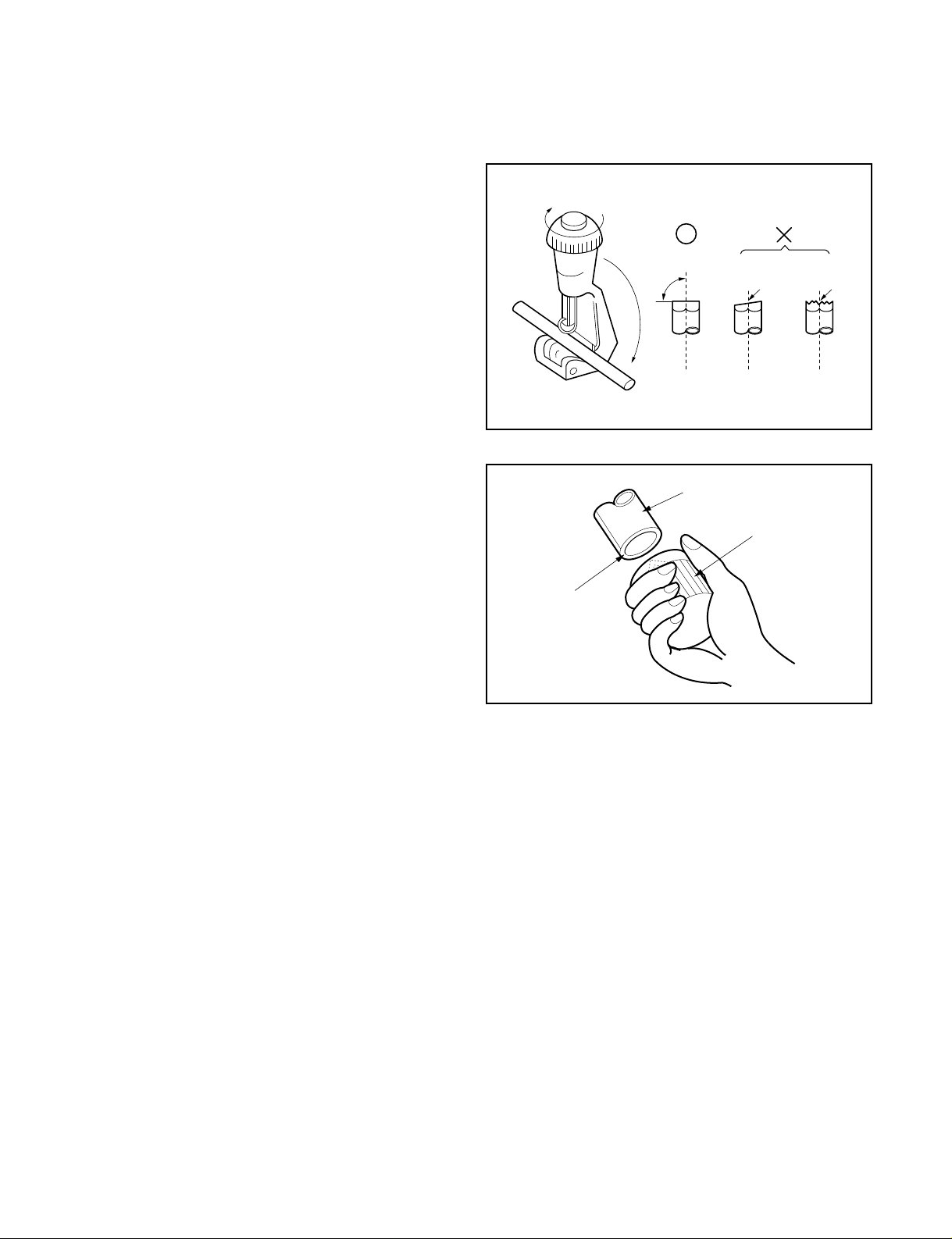
➁ Remove burrs.
• Remove burrs from cut edges of pipes.
• Turn the pipe end down to avoid the metal powder entering the pipe.
Caution:
If burrs are not removed, they may cause a gas
leakage.
2) Connection of piping
➀ Move the indoor tubing and drain hose to the hole
• Remove tubing holder and pull the tubing out of the chassis.
➁ Replace the tubing holder into original position
➂ Route the tubing and the drain hose staight backwards.
➃ Insert the connecting cable into the indoor unit through the hole.
• Do not connect the cable to the indoor unit
• Make a small loop with the cable for easy connection later.
➄ Tape the tubing and the connecting cable.
➅ Indoor unit installation.
➆ Connecting the pipings to the indoor unit.
• Align the center of the pipings and suffciently tighten the flare nut with fingers.
• Finally, tighten the flare nut with troque wrench until the wrench clicks.
When tightening the flare nut with troque wrench, ensure the direction for tightening follows the arrow on the
wrench.
90°
Pipe cutter
Slanted Rough
Pipe
Point down
Reamer
5-3. Piping of Indoor Unit
1) Preparation of piping

–21–
3) Precautions in bending
➀
If it is necessary to bend or stretch the tubing,
use the spring which is attached to the tubing in
stead of pipe bender.
• Please make a careful notice to make a smooth
line.
• Hold the tubing with your two hands closely and
then bend or stretch it slowly not to make any
crack.
• Remember that the radius (R) should not exceed
70mm (Refer to Fig. 1)
➁ Do not repeat the bending process to prevent the
tubing from cracking or crushing.
➂ Keep in mind that the bending part should not be
cracked and make the radius (R) as long as possible
(Refer to Fig. 2)`
Spring
R70mm
(Fig. 1)
(Fig. 2)
R
5-4. Connecting Piping to Outdoor Unit
1) Connecting pipings to the outdoor unit
➀ Upon connecting 4-way valves, please weld connecting pipes using elbows instead of connecting pipes with
flare nuts.
5-5. Connecting the Cable
➀ Open the control board cover from the outdoor unit by
removing the screws.
➁
Connect wires to the terminals on the control board
individually and secure the cables onto the control
board with clamp.
 Loading...