

LG LP-E5022HA, LP-E5022CL, LP-E5082CL, LP-E5082CA, LP-E5082HL Service Manual
...
Package
Air Conditioner
SERVICE MANUAL
MODEL: LP-E5020CL
LP-E5022CL/CA/HL/HA
LP-E5082CL/CA/HL/HA/ZL/ZA
LP-E5092CL/CA/HL/HA
LP-E50B0CL/CA/HL/HA

1. Preface
............................................................................................................................................
3
2. Dimensions
......................................................................................................................................
8
3. Refrigerant Cycle Diagram
.............................................................................................................
9
4. Wiring Diagram
..............................................................................................................................
10
5. Operation Details
...........................................................................................................................
18
6. Installation
.....................................................................................................................................
24
7. Operating
.......................................................................................................................................
40
8. 3-Way Valve
....................................................................................................................................
43
9. Troubleshootig Guide
...................................................................................................................
51
10. Electronic Control Device
.............................................................................................................
66
11. Schematic Diagram
.......................................................................................................................
68
12. Exploded View & Replacement Parts List
...................................................................................
70
– 2 –
CONTENTS

This service manual provides various service information, containing the mechanical and electrical parts and etc.
This package air conditioner was manufactured and assembled under the strict quality control system.
The refrigerant is charged at the factory. Be sure to read the safety precautions prior to servicing the unit.
1.1 Safety Precautions
¤ When servicing the unit, set the main SWITCH to OFF and remove the POWER SUPPLY cables.
¤Ł Observe the original lead dress. If a short circuit is found, replace all parts which have been overheated or
damaged by the short circuit.
¤Ø After servicing the unit, make an insulation resistance test to protect the customer from being exposed to shock
hazards.
1.2 Features
¤ Design for cooling and heating
¤ŁSuper energy efficiency
¤ØMicom Control
¤ŒWhisper quiet operation
¤ºWireless remote control
¤ Removable air filter
¤ 3 minute delay circuit
¤ 7 hour timer
¤ 3 step speeds for cooling/heating
¤ Plasma air purifying system
¤æAuto Restart
– 3 –
1. PREFACE
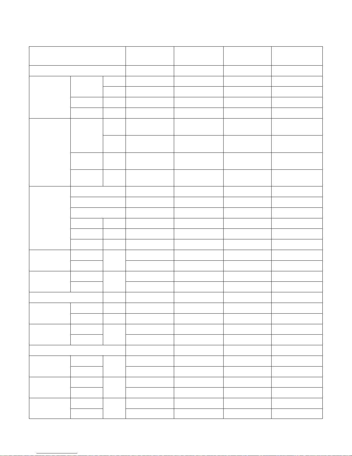
POWER SOURCE (ø, V, Hz)
COOLING CAPACITY Btu/h
W
INPUT W
CURRENT A
HEATING CAPACITY Btu/h
(W)
W
(W)
INPUT W
(W)
CURRENT A
(A)
MAKER
TYPE
COMPRESSOR MODEL
INPUT W
CURRENT A
CAPACITY Kcal/h
NOISE INDOOR dB(A)
LEVEL(1m) OUTDOOR
AIR INDOOR CMM
VOLUME OUTDOOR
REFRIGERANT R-22 Kg
HEAT INDOOR R/C/FPI
EXCHANGER OUTDOOR R/C/FPI
FAN INDOOR TYPE
OUTDOOR
ROOM TEMPERATURE CONTROL
NET INDOOR Kg
WEIGHT OUTDOOR
DIMENSIONS INDOOR mm
(W
× H × D) OUTDOOR
SVC LIQUID Inch
VALVE GAS (mm)
3.380 - 415,50 3,380 - 415,50 1,200,60 1,220,60
44,000 44,000 44,000 44,000
12,896 12,896 12896 12,896
3,600 3,600 3,600 5500
6 6 19 25
–
48,000
– 48,000
+(3,000)
–
14069
– 14,069
+(3,000)
–
3,500
– 4900
+(3,000)
–
5.5
– 24
+(13.5)
Tecumseh Tecumseh Copeland Copeland
Recipro Recipro Recipro Recipro
AVB5558EXG AVB5558EXG CR42K6-PFV CRMQ-0400-PFV
4,340 4,340 3,860 5,370
6.9 6.9 17.8 25.2
11,620 11,620 10,559 12,928
53 53 53 53
58 58 58 58
35 35 35 35
104 104 104 104
2.8 3.2 3.5 3.9
3/28/17 3/28/17 3/28/17 3/28/17
2/44/16 2/44/18 2/44/16 2/44/17
SIROCO SIROCO SIROCO SIROCO
PROPELLER PROPELLER PROPELLER PROPELLER
MICOM CONTROL MICOM CONTROL MICOM COTROL MICOM CONTROL
62 62 62 62
90 90 90 90
590 × 1,810 × 440 590 × 1,810 × 440 590 × 1,810 × 440 590 × 1,800 × 440
1,000 × 965 × 370 1,000 × 965 × 370 900 × 1,225 × 370 900 × 1,225 × 370
3/8 3/8 3/8 3/8
3/4 3/4 3/4 3/4
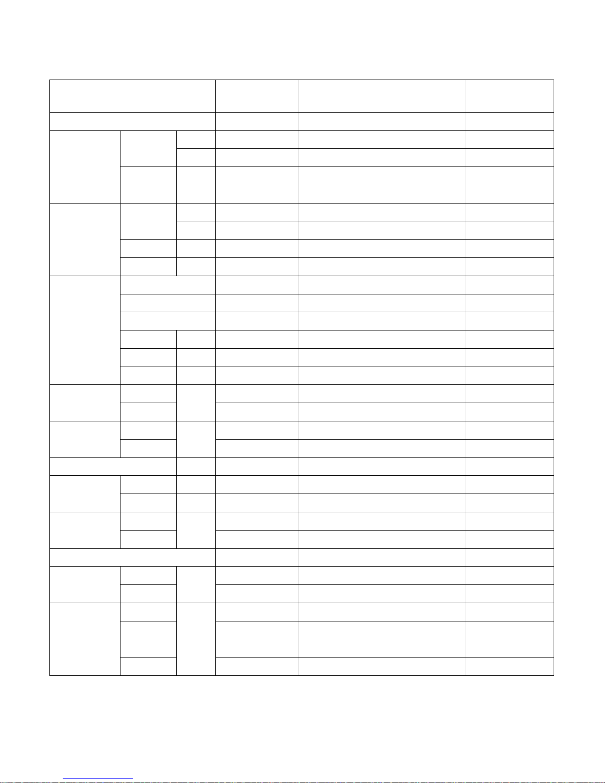
1.3 Product Specifications
– 4 –
MODEL
LP-E5082CL/CA
LP-E5082HL/HA
LP-E5082ZL/ZA
LP-E5020CL
LP-E5022CA
LP-E5022HL/HA
(Including Electiric
heater)
– 5 –
POWER SOURCE (ø, V, Hz)
COOLING CAPACITY Btu/h
W
INPUT W
CURRENT A
HEATING CAPACITY Btu/h
W
INPUT W
CURRENT A
MAKER
TYPE
COMPRESSOR MODEL
INPUT W
CURRENT A
CAPACITY Kcal/h
NOISE INDOOR dB(A)
LEVEL(1m) OUTDOOR
AIR INDOOR CMM
VOLUME OUTDOOR
REFRIGERANT R-22 Kg
HEAT INDOOR R/C/FPI
EXCHANGER OUTDOOR R/C/FPI
FAN INDOOR TYPE
OUTDOOR
ROOM TEMPERATURE CONTROL
NET INDOOR Kg
WEIGHT OUTDOOR
DIMENSIONS INDOOR mm
(W ¥ H ¥ D) OUTDOOR
SVC LIQUID Inch
VALVE GAS (mm)
3,220,60 3,220,60 3,380,60 3,380,60
44,000 44,000 44,000 44,000
12,896 12,896 12,896 12,896
6,000 6,000 4,600 4,600
10 10 8.2 8.2
– 48,000 – 48,000
– 14,069 – 14,069
– 5,000 – 4,500
– 9 – 8
Copeland Copeland Copeland Copeland
Recipro Recipro Recipro Recipro
CRNQ-0501-ES8 CRNQ-0501-ES8 CRNQ-0501-ES8 CRNQ-0501-ES8
6,210 6,210 6,210 6,210
19.0/11.0 19.0/11.0 19.0/11.0 19.0/11.0
61,500 61,500 61,500 61,500
53 53 53 53
58 58 58 58
35 35 35 35
104 104 104 104
3.5 3.9 4 4.2
3/28/17 3/28/17 3/28/17 3/28/17
2/44/16 2/44/18 2/44/16 2/44/18
SIROCO SIROCO SIROCO SIROCO
PROPELLER PROPELLER PROPELLER PROPELLER
MICOM CONTROL MICOM CONTROL MICOM CONTROL MICOM CONTROL
62 62 62 62
90 90 90 90
590 × 1,800 × 440 590 × 1,800 × 440 590 × 1,800 × 440 590 ×1,800 × 440
900 × 1225 × 370 900 × 1225 × 370 900 × 1225 × 370 900 × 1225 × 370
3/8 3/8 3/8 3/8
3/4 3/4 3/4 3/4
MODEL
LP-E50B2CL/CA
LP-E50B2HL/HA
LP-E50B2ZL/ZA
LP-E5090CL
LP-E5092CA
LP-E5092HL/HA
– 6 –
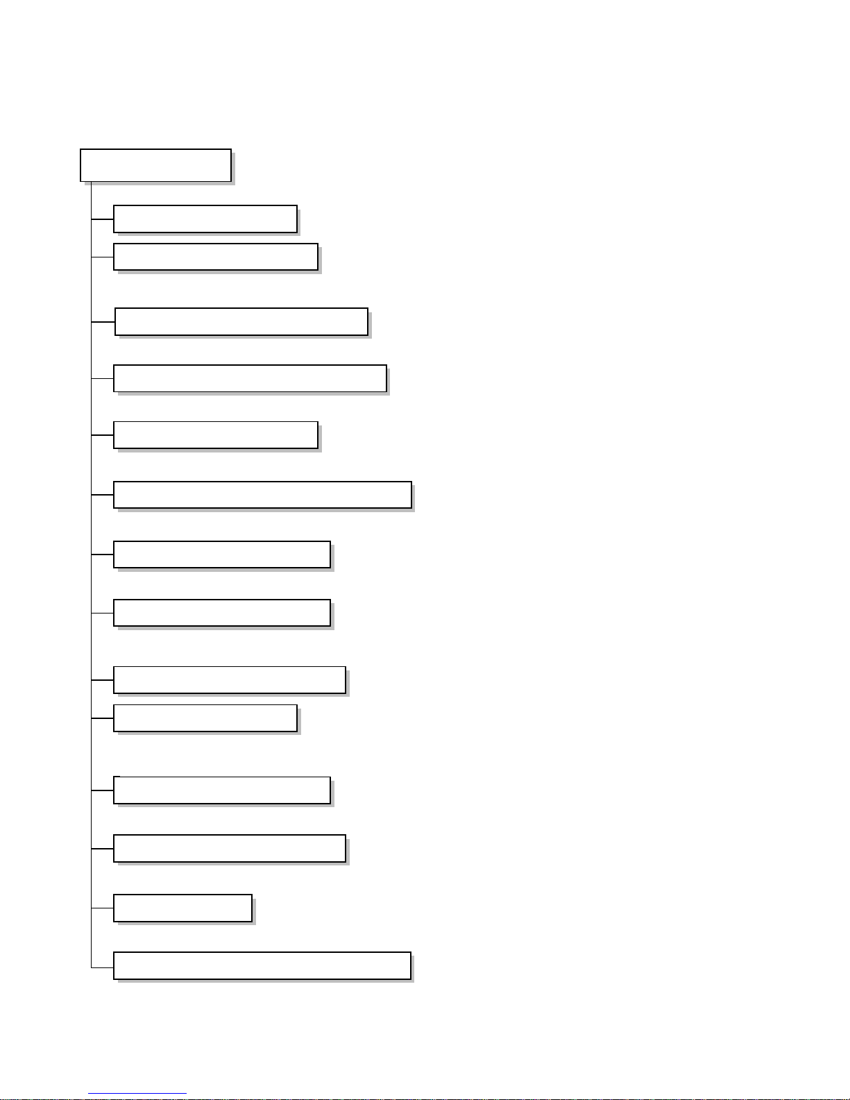
1.4 Functions
Indoor Unit
Power Switch ON/OFF
Operation Mode Control
Sensing the room temperature
Controlling the room temperature
Starting Current Control
Sensing Heat Exchanger Temperature
Timer Delay Safety Control
Indoor Fan Speed Control
Operation Indication lamps
Temperature Setting
Airflow Direction Control
Room temperature Display
Timer Control
Sensing Discharge Air Temperature
• Cooling, Soft Dry, Auto, Fan ¢¡Cooling Model •
Cooling, Heating, Soft Dry, Fan ¢¡Heat Pump Model
• Room temperature sensor (Thermistor)
• Maintains the room temperature in accordance with the setting temperature.
• Indoor fan is delayed for 3 sec at the starting.
• Heat exchanger temperature sensor (Thermistor)
• Restarting is inhibited for approx. 3 minutes.
• High, Med, Low
• Up : up to 30°C
• Down : down to 16°C
• Airflow direction Automatic and Manual control
• Low, 10° ~ 35°C, Hi
• Off Timer (1, 2, 3....7 hour)
• Discharge temperature sensor <Thermistor>
• Apply Heat Pump Model Only.
– 7 –
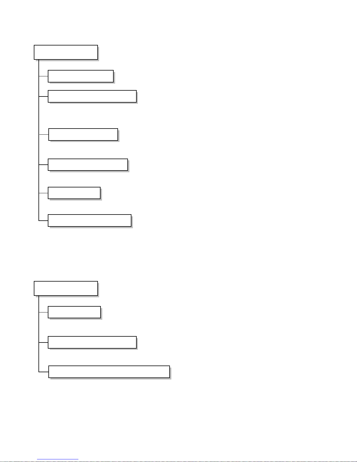
Remote Control
Operation ON/OFF
Operation Mode Selection
• Cooling, Soft Dry, Auto, Fan ¤I Cooling Only Model
• Cooling, Heating, Soft Dry, Fan, ¤I E/heater Heat Pump Model
Fan Speed Selection
Setting the temperature
Timer Control
Airflow Direction Control
• High, Medium, Low
• Up or Down
• Off Timer(1, 2, 3...7 hour)
• Airflow direction Auto-Swing and Manual control
Outdoor Unit
Deice Control
Outdoor Fan Speed Control
Sensing Heat Exchanger Temperature
• De-ice PCB
• One speed
• Heat exchanger temperature sensor (Thermistor)
118
37.3
50
80
58.2
959
605.5
440
590
540
1513 243
548899
370
125
210
290
1220
460
460
505
90130
640
900
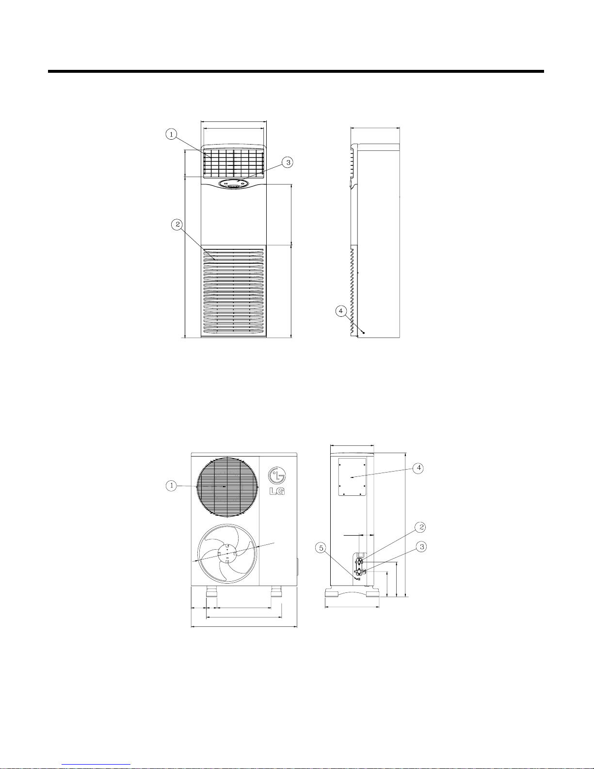
1) Indoor Unit
2) Outdoor Unit
– 8 –
2. DIMENSIONS
¤ Air Outlet Vent
¤ŁAir Inlet Vent
¤ØWindow display
¤ŒEarth Screw
¤ Air Outlet Vent
¤ŁLiquid Side SVC Valve
¤ØGas Side SVC Valve
¤ŒControl Box
¤ºEarth Screw
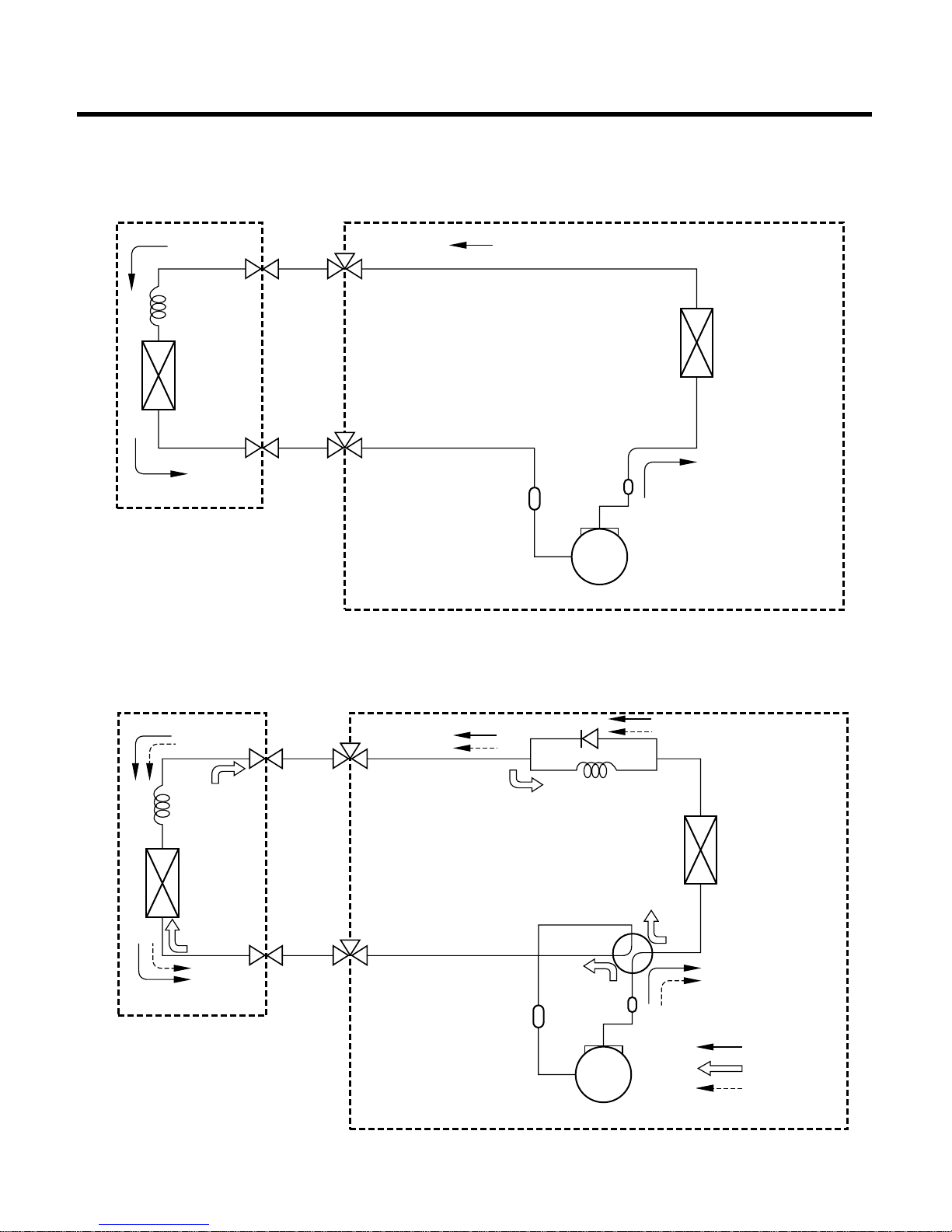
3.1
Cooling Cycle
– 9 –
3. REFRIGERANT CYCLE DIAGRAM
INDOOR UNIT
LIQUID SIDE
CAPILLARY
TUBE
HEAT
EXCHANGER
ACCUMULATOR
MUFFLER
COMPRESSOR
HEAT
EXCHANGER
CAPILLARY
TUBE
HEAT
EXCHANGER
HEAT
EXCHANGER
3-WAY VALVE
GAS SIDE
3-WAY VALVE
LIQUID SIDE
CHECK VALVE
CAPILLARY TUBE
4-WAY VALVE
MUFFLER
COMPRESSOR
COOLING
HEATLNG
DE-ICE
ACCUMULATOR
3-WAY VALVE
GAS SIDE
3-WAY VALVE
OUTDOOR UNIT
INDOOR UNIT OUTDOOR UNIT
3.2
Cooling and Heating Cycle
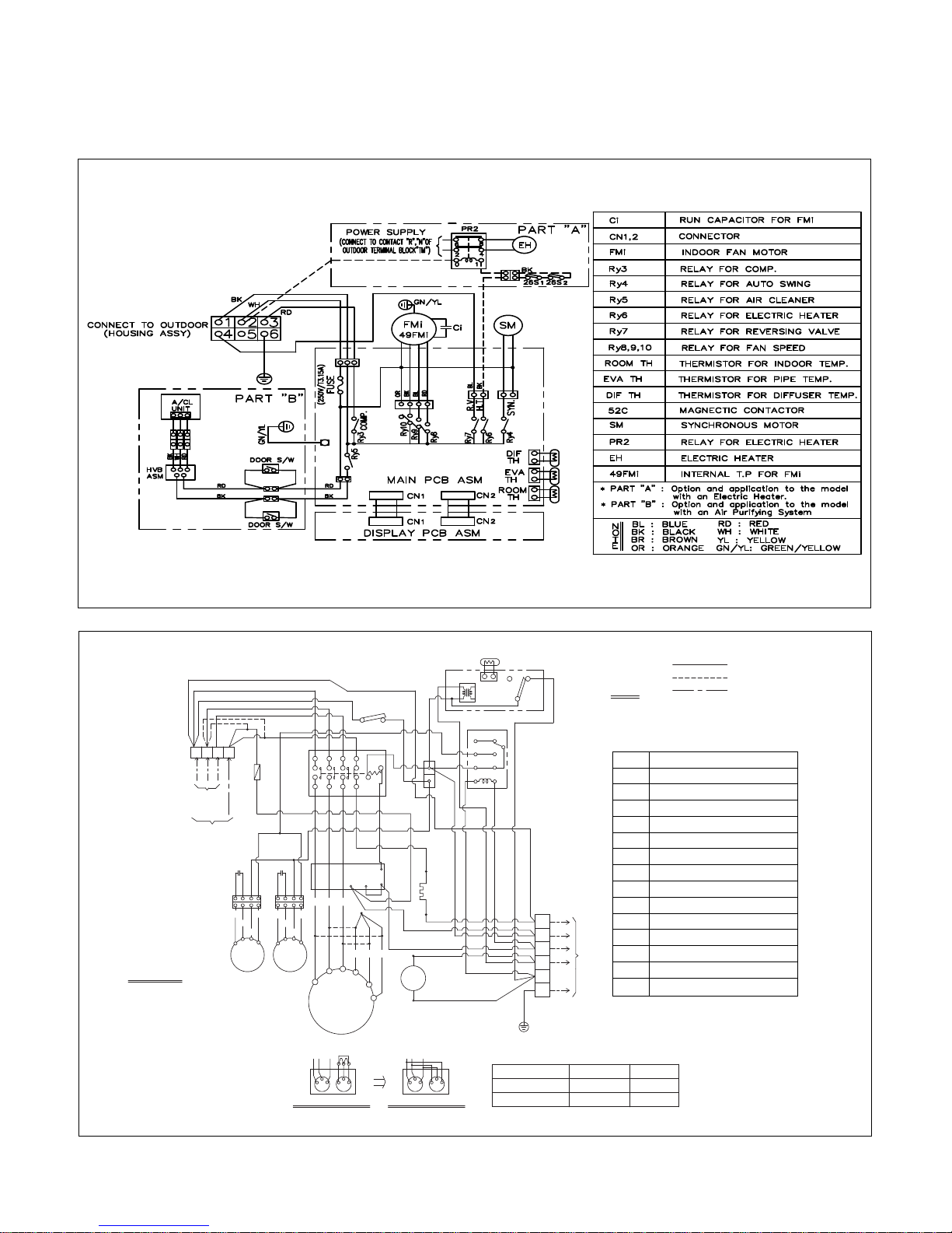
Indoor & Outdoor Unit Circuit Diagram
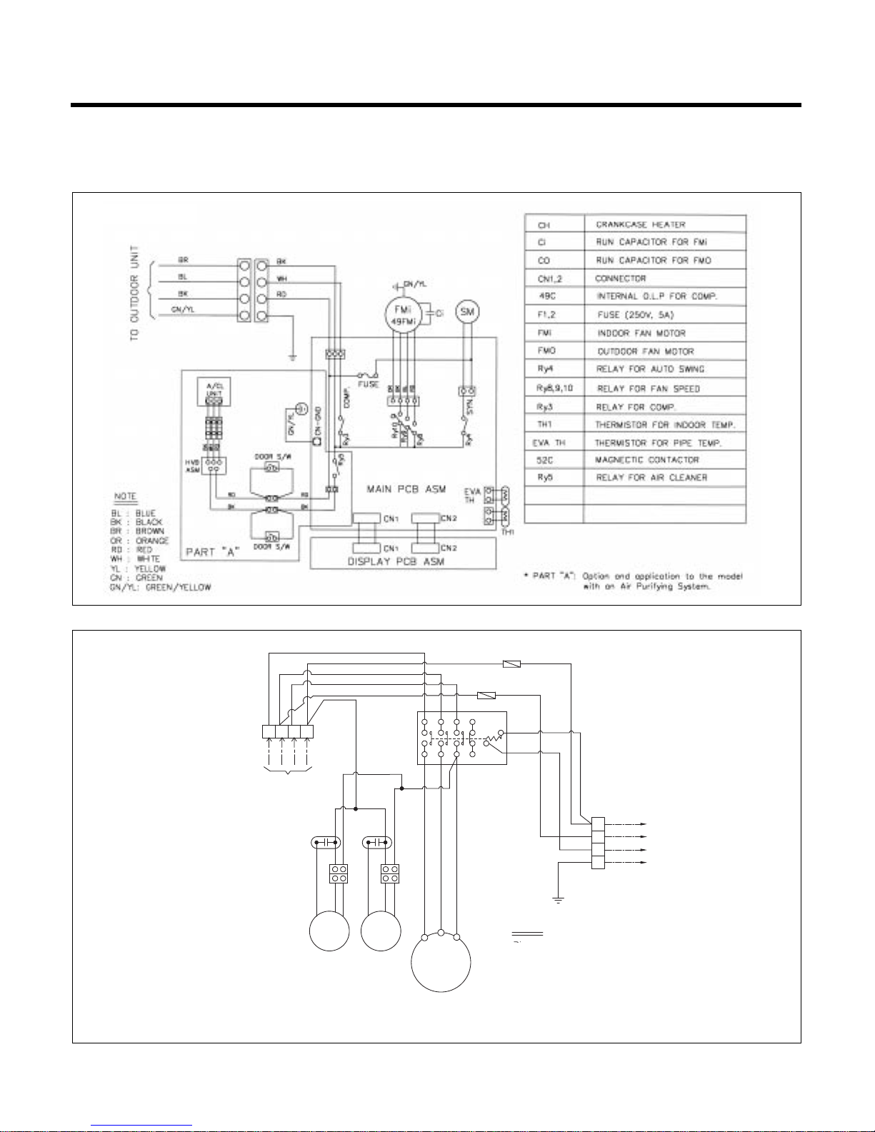
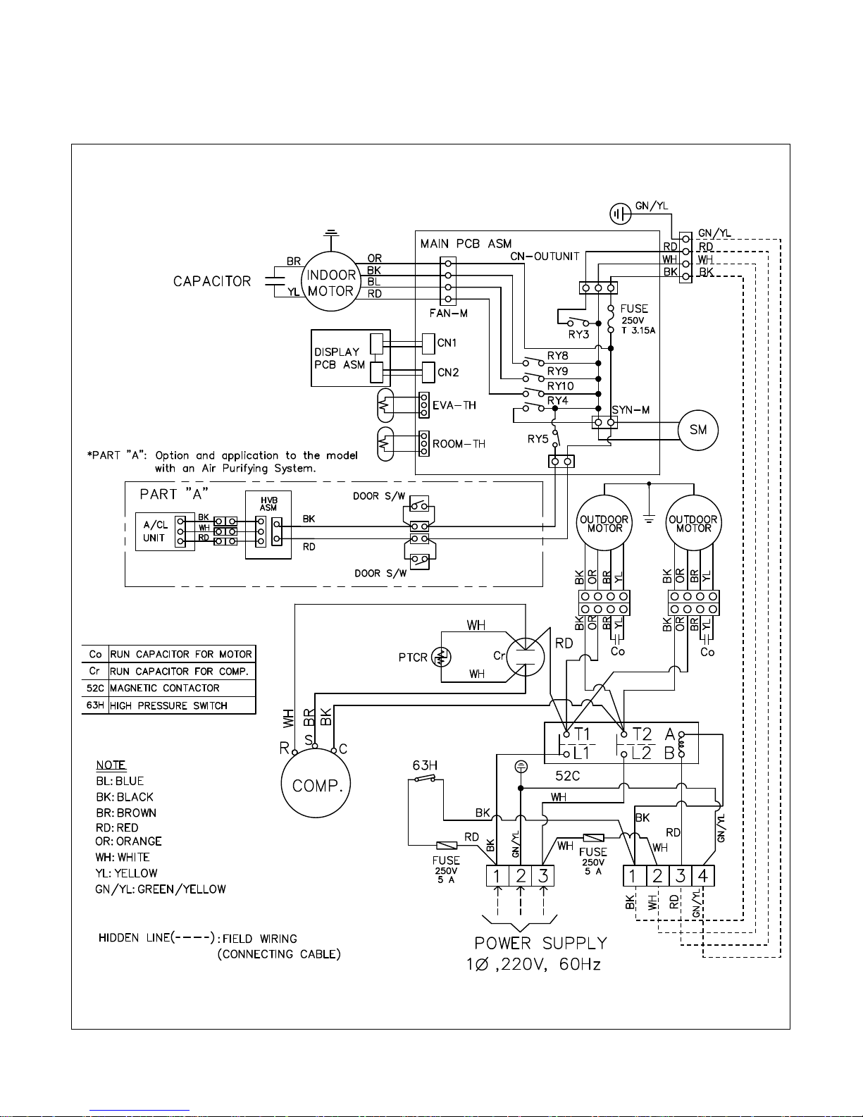
(1) LP-E5082CL/CA
– 10 –
4. WIRING DIAGRAM
INDOOR UNIT
POWER
RELAY
NOTE
BL
BK
BR
OR
RD
WH
YL
GN/YL
BLUE
BLACK
BROWN
ORANGE
RED
WHITE
YELLOW
GREEN/YELLOW
:
:
:
:
:
:
:
:
TERMINAL
BLCOCK
BR
BK
BK
BK
BK
RD
RD
BK
BK
BK
BK
OROR BK
OR BK
FAN
MOTOR
FAN
MOTOR
COMP.
T1
T2
T3
OR BK
YLYL
WH
CAPACITOR CAPACITOR
TERMINAL
BLOCK
TO INDOOR UNIT
1
2
3
4
WH
WH
RD
WH
FUSE
(250V 5A)
FUSE
(250V 5A)
12345631
32
B
A
POWER SUPPLY
R S T N
OUTDOOR ELECTRIC
CIRCUIT
– 11 –
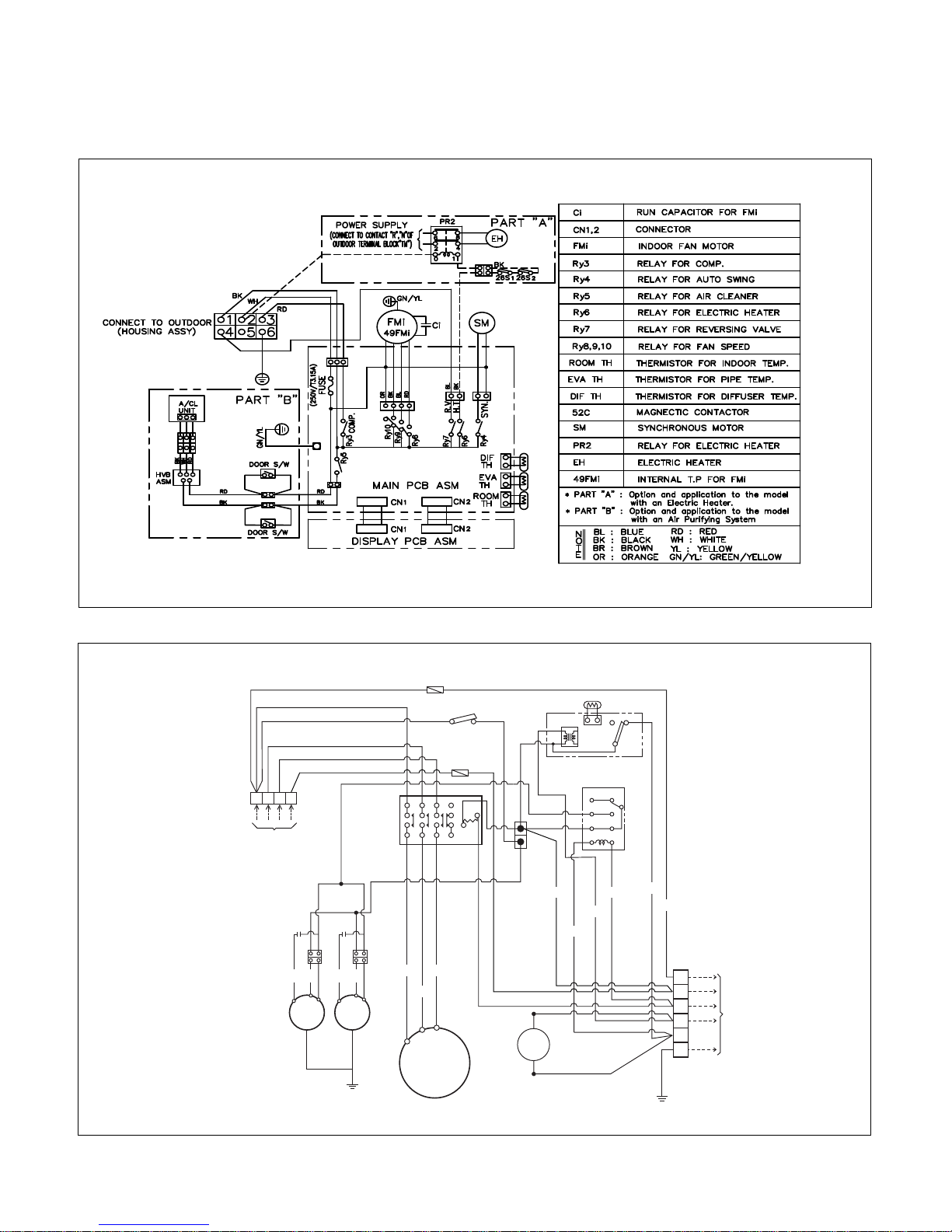
(2) LP-E5082HL/HA/ZL/ZA
INDOOR ELECTRIC CIRCUIT
R
TERMINAL
BLOCK
POWER SUPPLY
POWER
RELAY
S T N
BK
BK
BK
WH
WH WH
RD
OR
BK
HIGH PRESSURE S/W
WH
Deice PCB
C TH
TNS
NO
NC
WH
OR
BK
POWER
RELAY
12345631
T/B1
T/B2
32
B
A
FAN
MOTOR
FAN
MOTOR
YL BK
OR
BK
T3
T2
T1
RD
WH
COMP.
1 2
3 4
5 6
7 8
YL BK
OR
BK
BK
BL
BL
BK
WH
CAPACITOR CAPACITOR
REVERSING
VALVE
BR
BL
BR
BL
GN/YL
GN/YL
TERMINAL BLOCK
To the indoor unit
1
2
3
4
5
6
BK
WHWH
YL
BK
RD
Fuse
(250V 5A)
Fuse
(250V 5A)
OUTDOOR UNIT WIRING DIAGRAM
– 12 –
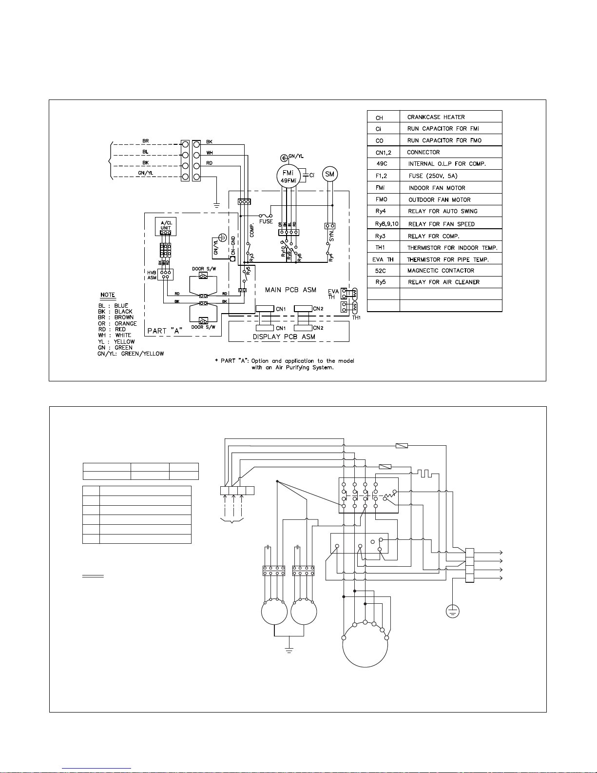
(3) LP-E5020CL / LP-E5022CL/CA
WIRING DIAGRAM

– 13 –
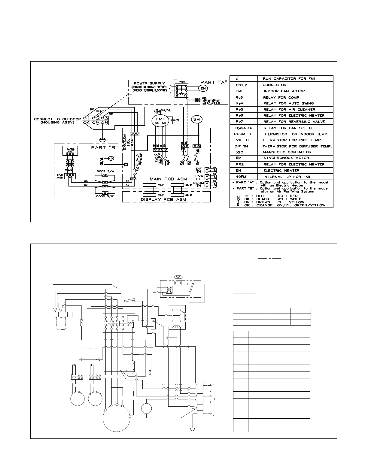
(4) LP-E5022HL/HA
– 14 –
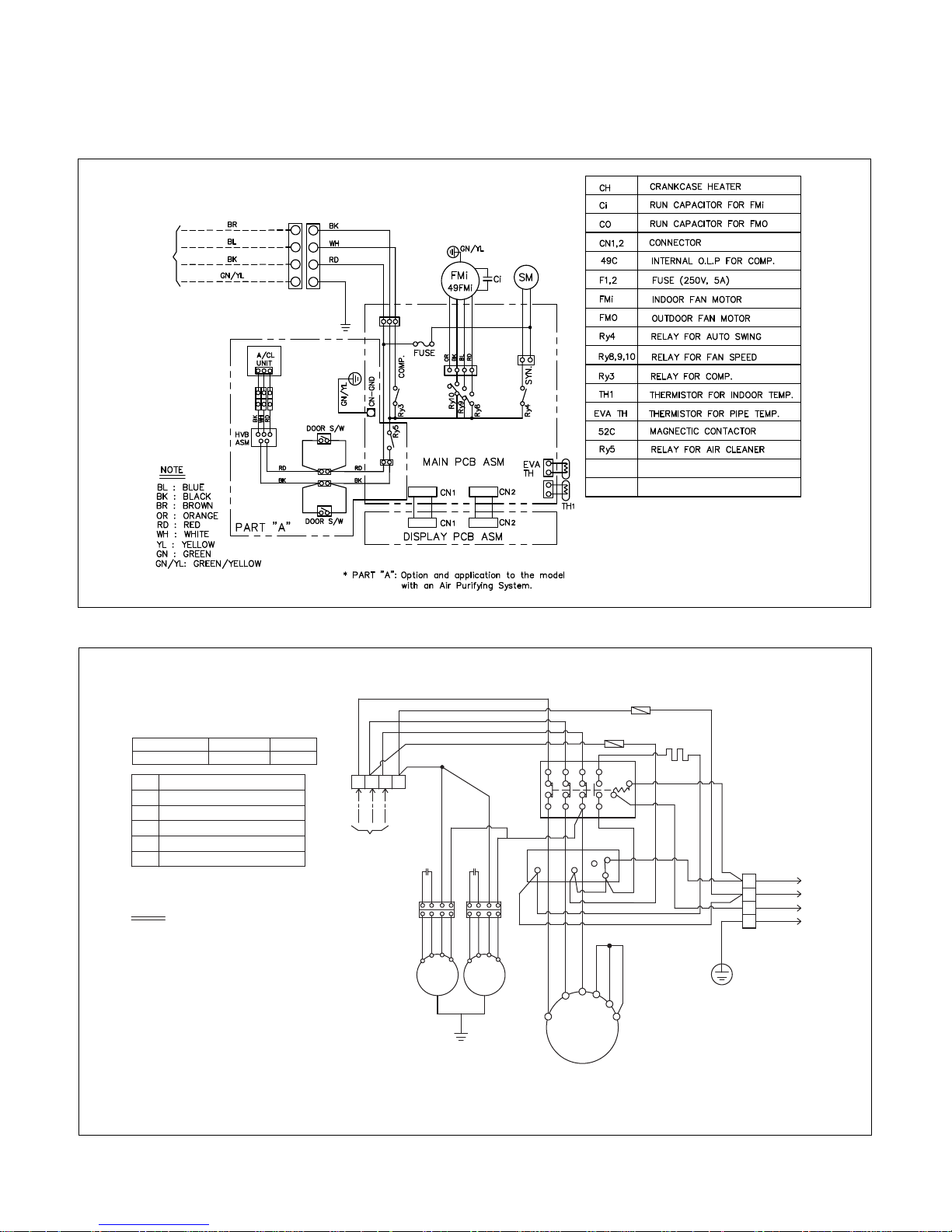
(5) LP-E50B0CL/CA
TO OUTDOOR UNIT
INDOOR UNIT
EOCR Current Setting.
POWER SUPPLY
Co
52C
51C
Tmo
Tm
CH
NOTE
BL
BK
BR
RD
OR
WH
YL
GN/YL
BLUE
BLACK
BROWN
RED
ORANGE
WHITE
YELLOW
GREEN/YELLOW
3ø,3Wires 220V
Tm
52C
COMP.
51C
BK
RD
WH
RD
OR
BK
BK
Co
WH
BK
RD RDRDRD
GN/YL
WH
U
V
Z
W X
Y
L1 L2
2 4 6 32
1 3 5 31
B
A
Tb
Ta
Tc
BL
Co
Outdoor
Motor
YL BROR BK YL BR OR BK
Outdoor
Motor
RD
FUSE
250V 5A
FUSE
250V 5A
BL
RD
BL
BK
BK
BK
To Indoor Unit
WH
RD
GN/YL
Tmo
1
2
3
4
RD
WH
CH
R S T N
:
:
:
:
:
:
:
:
RUN CAPACITOR FOR MOTOR
MAGNETIC CONTACTOR
EOCR
TERMINAL BLOCK(Outdoor Unit)
MAIN TERMINAL BLOCK
CRANKCASE HEATER
3ø,220V,60Hz
CURRENT(A
)
30
TIME(sec
)
5
OUTDOOR WIRING DIAGRAM
– 15 –
(6) LP-E50B0HL/HA
INDOOR ELECTRIC CERCUIT
TM
3ø, 3 wires,
220V.
WH
BK
1 3 5 31
A
1 2
3 4
5 6
7 8
B
T/B1
T/B2
2
L1 L2
Ta
Tc
4 6 32
BK
BK
BK
YL
FMo1
49FMo
FMo2
49FMo
OR
BR
BK
YL OR
BR
BK
CM
BK
WH
WH
BL
BK
RD BK
BR
BR
BL
Tmo
To the indoor unit
GN/YL
GN/YL
BL
BL
WH
20SV
RD
WH
RD
U
V
W
X
Y
Z
BK
Co Co
RD
BK
D.P
C TH
TNS
NO
NC
WH
WH WH
YL
WH
BK
BK
OR
RD
WH
WH
52C
CH
63H2
52F1
51C
F1
R S T N
1
2
3
4
5
6
63H2
C TH
63H1
CH
20SV
52C
TM
52F1
51C
CM
Co
FMo
F1
DP
TMo
HIGH PRESSURE SWITCH FOR HEATING
THERMISTOR FOR PIPE TEMP.
INTERNAL T.P FOR FMo
CRANKCASE HEATER
REVERSING COIL
MAGNETIC CONTACTOR
MAIN TERMINAL BLOCK
RELAY FOR FMO
E.O.C.R
COMPRESSOR
RUN CAPACITOR FOR FMo
OUTDOOR FAN MOTOR
FUSE (250V, 10A)
DEICER PCB
TERMINAL BLOCK
(
Caution
)
1. Basic wiring is 3ø,3 wires, 220V.
2. For setting E.O.C.R current
POWER SUPPLY
3ø,220V,60HZ
3ø,380V,60HZ
CURRENT(A)
30.0
17.5
TIME(sec)
5
5
WIRING FOR 220V
WIRING OF FIELD
(CONNECTING WIRE)
NOTE
BL
BK
BR
OR
BLUE
BLACK
BROWN
ORANGE
:
:
:
:
RD
WH
YL
GN/YL
RED
WHITE
YELLOW
GREEN/YELLOW
:
:
:
:
Outdoor Unit Wiring Diagram
– 16 –
(7) LP-E5092CL/CA
TO OUTDOOR UNIT
INDOOR UNIT
EOCR Current Setting.
POWER SUPPLY
Co
52C
51C
Tmo
Tm
CH
NOTE
BL
BK
BR
RD
OR
WH
YL
GN/YL
BLUE
BLACK
BROWN
RED
ORANGE
WHITE
YELLOW
GREEN/YELLOW
3ø,3Wires 220V
Tm
52C
COMP.
51C
BK
RD
WH
RD
OR
BK
BK
Co
WH
BK
RD RDRDRD
GN/YL
WH
U
V
Z
W X
Y
L1 L2
2 4 6 32
1 3 5 31
B
A
Tb
Ta
Tc
BL
Co
Outdoor
Motor
YL BR OR BK YL BR OR BK
Outdoor
Motor
RD
FUSE
250V 5A
FUSE
250V 5A
BL
RD
BL
BK
BK
BK
To Indoor Unit
WH
RD
GN/YL
Tmo
1
2
3
4
RD
WH
CH
R S T N
:
:
:
:
:
:
:
:
RUN CAPACITOR FOR MOTOR
MAGNETIC CONTACTOR
EOCR
TERMINAL BLOCK(Outdoor Unit)
MAIN TERMINAL BLOCK
CRANKCASE HEATER
3ø,380V,60Hz
CURRENT(A
)
17.5
TIME(sec
)
5
OUTDOOR WIRING DIAGRAM
– 17 –
(8) LP-E5092HL/ZL/HA/ZA
INDOOR ELECTRIC CIRCUIT
TM
3ø, 3 wires,
220V.
a
WH
BK
1 3 5 31
A
1 2
3 4
5 6
7 8
B
T/B1
T/B2
2
L1 L2
Ta
Tc
4 6 32
BK
BK
BK
YL
FMo1
49FMo
FMo2
49FMo
OR
BR
BK
YL OR
BR
BK
CM
(
Caution
)
1. Basic wiring is 3ø,4 wires, 380V.
2. For changing the running
voltage to 220V, please change
the wiring by the next steps.
1st) Remove the 2 wires from
the "N" of the main terminal
block
2nd) Fit the removed 2 wires
on the "S' of the main
terminal block
3rd) Change the compressor
wires
BK
WH
WH
BL
BK
RD BK
BR
BR
BL
Tmo
To the indoor unit
GN/YL
GN/YL
BL
BL
WH
20SV
RD
WH
RD
U
V
W
X
Y
Z
BK
Co Co
RD
BK
D.P
C TH
TNS
NO
NC
WH
WH WH
YL
WH
BK
BK
OR
RD
WH
WH
52C
CH
63H2
52F1
51C
F1
b
3ø, 4 wires,
380V.
R S T N
1
2
3
4
5
6
3ø,4 wires,380V. 3ø,3 wires,220V.
V
U WYX Z
V
U WYX Z
3. For setting E.O.C.R current
POWER SUPPLY
3ø,220V,60HZ
3ø,380V,60HZ
CURRENT(A)
30.0
17.5
TIME(sec)
5
5
63H2
C TH
63H1
CH
20SV
52C
TM
52F1
51C
CM
Co
FMo
F1
DP
TMo
HIGH PRESSURE SWITCH FOR HEATING
THERMISTOR FOR PIPE TEMP.
INTERNAL T.P FOR FMo
CRANKCASE HEATER
REVERSING COIL
MAGNETIC CONTACTOR
MAIN TERMINAL BLOCK
RELAY FOR FMO
E.O.C.R
COMPRESSOR
RUN CAPACITOR FOR FMo
OUTDOOR FAN MOTOR
FUSE (250V, 10A)
DEICER PCB
TERMINAL BLOCK
WIRING FOR 380V
WIRING FOR 220V
WIRING OF FIELD
(CONNECTING WIRE)
NOTE
BL
BK
BR
OR
BLUE
BLACK
BROWN
ORANGE
:
:
:
:
RD
WH
YL
GN/YL
RED
WHITE
YELLOW
GREEN/YELLOW
:
:
:
:
Outdoor Unit Wiring Diagram
– 18 –
5. OPERATION DETAILS
(1) The function of main control
1. Time Delay Safety Control
• 3min
...
The compressor is ceased for 3 minutes to balance the pressure in the refrigeration cycle.
(Protection of compressor)
• 3sec
...
The indoor fan is ceased for 1~3 seconds to prevent relay noise.
(Protection of fan relay and micro chip)
• 1min
...
The 4-way valve is ceased for 30 sec. to prevent the refrigerant-gas abnormal noise when the Heating
operation is OFF or switched to the other operation mode.
2. Airflow Direction Control
• This function is to swing the louver left and right automatically and to set it at the desired position.
• The procedure is as the following.
1st : Press the ON/OFF Button to operate the product.
2nd : Press the Airflow Direction Control Button to swing the louver left and right automatically.
(Remote controller)
3rd : Repress the Airflow Direction Control Button to set the louver as the desired position.
(Remote controller)
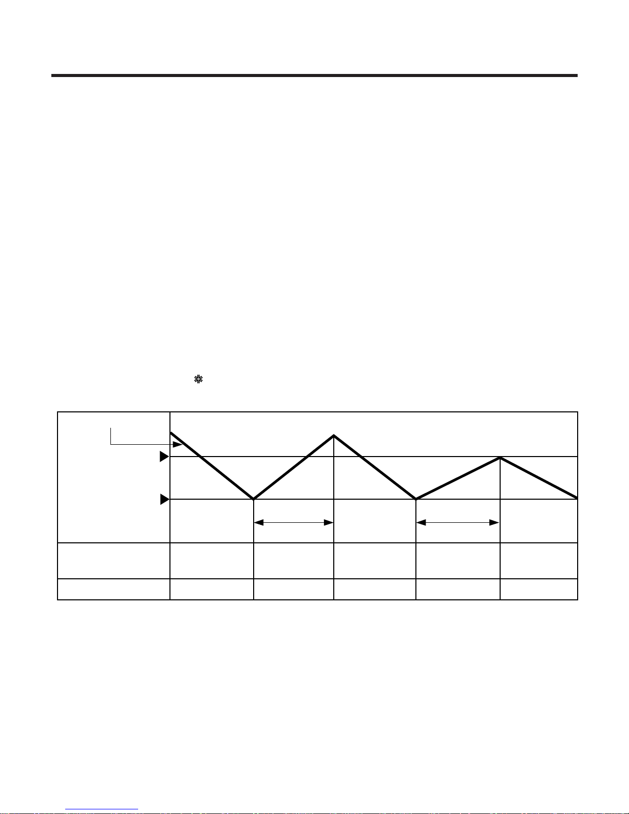
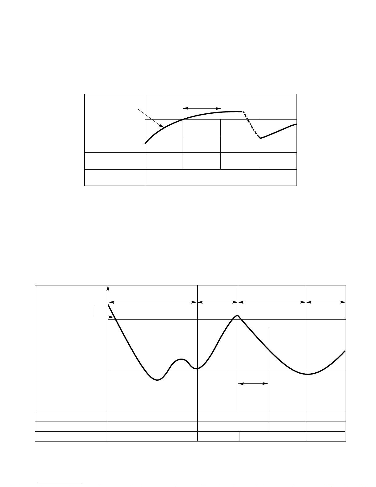
3. Cooling Mode Operation
• When selecting the Cooling( ) Mode Operation, the unit will operate according to the setting by the
controller and the operation diagram is as following
Intake Air temp.
Setting Temp. +1°C
(Compressor ON)
Setting Temp. -1°C
(Compressor OFF)
Indoor Fan Speed
Selecting
fan speed
Selecting
fan speed
Selecting
fan speed
Selecting
fan speed
Selecting
fan speed
3 minutes 3 minutes
Compressor ON OFF ON OFF ON
– 19 –
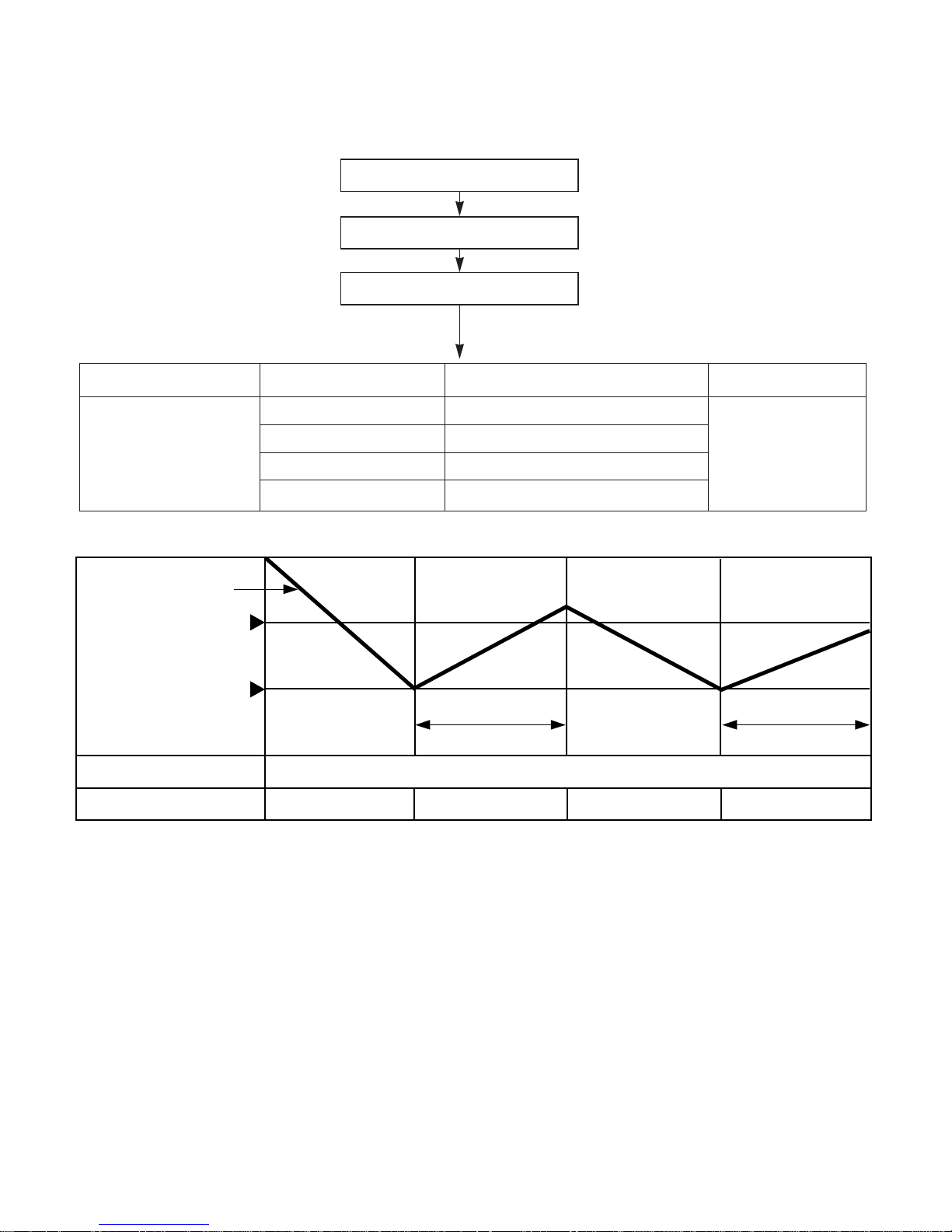
4. Auto Operation (Cooling Model only)
ƒUThe operation procedure is as following.
ƒƒUU
Auto Operation for Cooling
Press Start/Stop Button
Select Auto Operation Mode
Check the Room temperature
Operation Condition Intake-air Temperature Setting temperature Fan speed
Over 26°C 25°C
Over 24°C~below 25.5°C Intake air -1.0°C
Over 22°C~below 23.5°C Intake air -0.5°C
below 21.5°C Intake air Temperature(18°C, MAX)
When Switch to
Auto Operation
Controlled
by Fuzzy logic
Intake Air Temp.
Indoor Fan Speed
Compressor ON OFF
Fuzzy Speed
ON OFF
Setting Temp. +1°C
(Compressor ON)
Setting Temp. -1°C
(Compressor OFF)
3 minutes 3 minutes
– 20 –
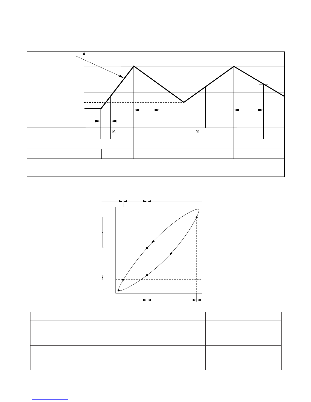
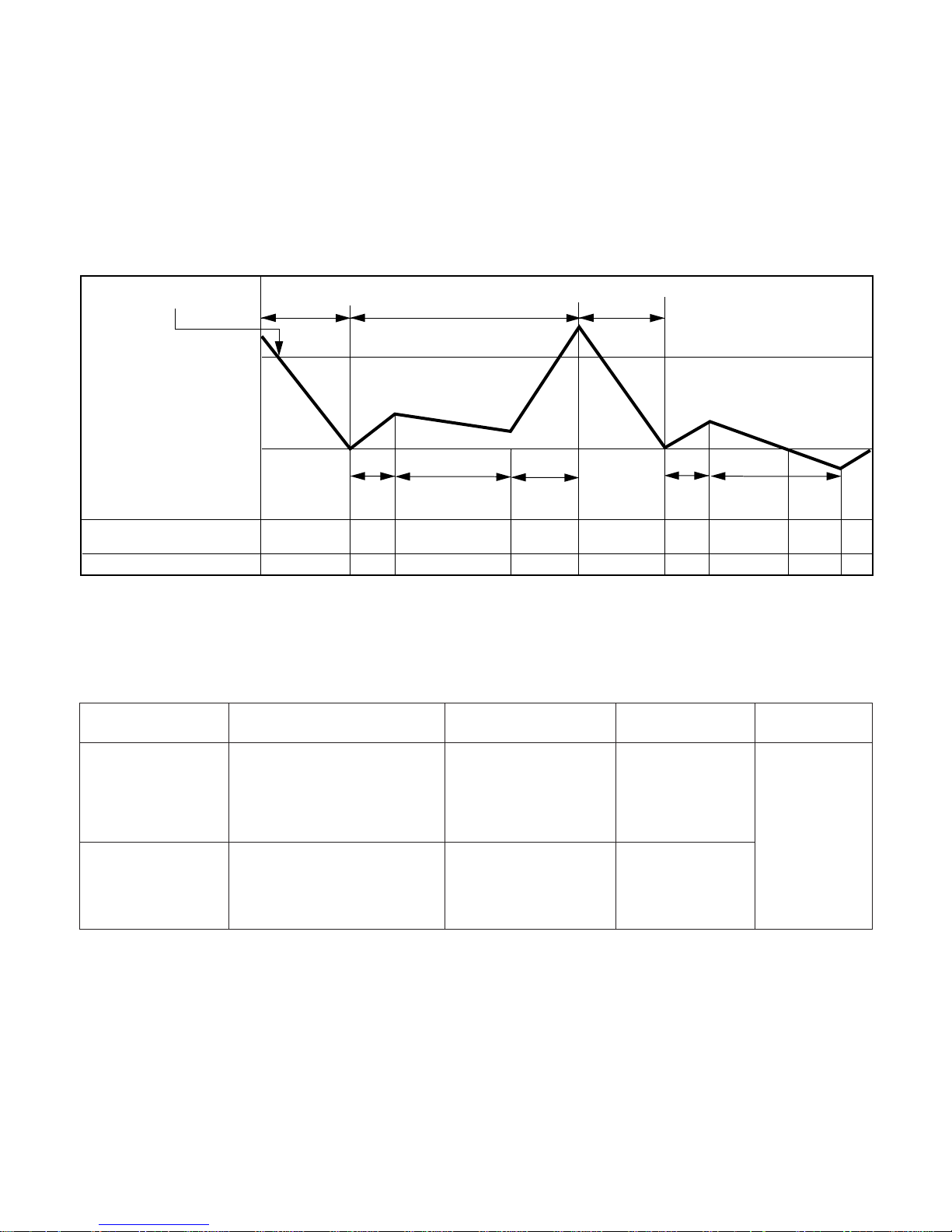
5. Heating Mode Operation
The unit will operate according to the setting by the remote controller and the operation diagram is shown as
following.
Intake Air Temp.
Setting Temp.
(Compressor ON)
Setting Temp. -1°C
Indoor Fan Speed
Compressor
Electric Heater(Option)
ON
ON
OFF ON OFF
OFFOFF ON OFF
OFF
Hot
Start
minimum
10sec.
minimum
1min
minimum
10sec.
OFF
A A
OFFLOW
LOW
LOW
Setting Temp. +1°C
(Compressor OFF)
Selecting
fan speed
Selecting
fan speed
• A point: The indoor pipe temperature to be less then 35°C or Discharge air Temperature to be less than 29°C.
The indoor fan operates for minimum 10sec. even if the indoor pipe temperature falls lower than35°C
or the discharge air Temperature falls lower than 29°C.
Low(V)Stop(VI)
39˚C
Discharge Air Temp.
Indoor Pipe Temp.
34˚C
28˚C
26˚C
Selecting Fan Speed(IV)
Low(II)Stop(I)
(Hot-Start Operating)
Heating Start
(Hot-Start Release Point)
Selecting Fan Speed(III)
¡ During heating operation, the operating procedure of the indoor fan is as the following.
Step Indoor fan speed Pipe temp. Air discharge temp.
¥ Off ≤28°C(Hot start operating) –
¥– Low ≥28°C <39°C
¥† Selecting speed ≥28°C ≥39°C
¥‡ Selecting speed ≥28°C >34°C
¥· Low ≥26°C ≤34°C
¥ Off ≤26°C –
6. Hot-Start Control
• The indoor fan stops until the evaporator piping temperature will be reached to 28°C.
• During heating operation, if piping temperatures fall below 26°C fan stops.
• The operation diagram is as following.
7. Defrost Control
• Defrost operation is controlled by timer and sensing temperature of outdoor pipe.
• The first defrost starts only when the outdoor pipe temperature falls below -6°C after 45 minutes passed from
starting of heating operation and more than.
• Defrost ends after 10 minutes pass from starting of defrost operation or when the outdoor pipe temperature rises
over 12°C even if before 10 minutes.
• The second defrost starts only when the outdoor pipe temperature falls below -6°C after 45 minutes pass from
ending of the first defrost and more than.
– 21 –
INDOOR PIPE
TEMP.
INDOOR FAN
SPEED
Selecting
fan speed
OFF OFFLOW
1min
Maximum
COMPRESSOR ON
28°C
26°C
More than 45 minutes of
heating operation
Outdoor Pipe Temp.
Indoor Fan
Compressor
4-Way Valve
ON
ON
ON
ON
OFF
ON
OFF
HOT-
START
ON
ON OFF OFFON
12°C
(Defrost OFF)
-6°C
(Defrost ON)
Within
10minutes
Defrost
Defrost
More than 45 minutes of
heating operation
Less than 5 minutes
11. Child Lock function
This function is to operate Air conditioner only by Remocon.
The procedure is as the following
1st: Press the 2 buttons of the temperature control simultaneously, to raise-to lower on the Display Panel of the
product for more 3 seconds.
2nd: The buzzer sounds and then the window of Display Panel shows
LLOOCC
(LOC) mark.
3rd: To release this function, the reverse again the operating procedure could be done.
¡ During this function is operating, any buttons of Display Panel don't work. But it is possible to operate with
Remote controller.
– 22 –
9. Protection of the evaporator pipe from frosting
• Compressor and outdoor fan stop when indoor pipe temperature is below -2°C and restart at the pipe temperature
is above 12°C.
10. Air Purifying Operation(CA, HA, ZA Model only)
8. Soft Dry Operation Mode
• During Soft Dry Operation, the compressor ON temperature is the setting temperature plus 2°C, the compressor OFF temperature is the setting temperature minus 1°C.
• When the room temperature rises over the compressor ON temperature, the operation mode is switched to the
Cooling mode.
• When the room temperature falls between the compressor ON temperature and OFF temperature, the operation mode is switched to the Soft Dry Operation.
• The operation diagram is shown below.
Intake Air Temp.
Indoor Fan Speed
LOW
Selecting
fan speed
Selecting
fan speed
LOW LOW LOW LOW
Compressor OFFON ONON OFF OFF ON
LOW
OFF
Setting Temp. +2°C
(Compressor ON)
Setting Temp. -1°C
(Compresso OFF)
Operation
Cooling
Cooling
operation
Dry operation
3 min. 3 min.
10 min.
maximum
7 min.
maximum
10 min.
Mode Selecting
Operating Mode
Fan Speed
Outdoor OFF
Initial Starting of
Air purifying
Operation
- Low at the initial
- But could be
switched to Med. Hi
OFF
- Outdoor not operating
- Fan operating + Air purifying
operating
Repress Air
purifying
Button or
ON/OFF
Button
When switched to
Air purifying operation
Selecting Speed of
Main Operating Mode
ON or OFF
depend on main
operating
condition.
- Outdoor operating
- Main Operating +
Air purifying operating
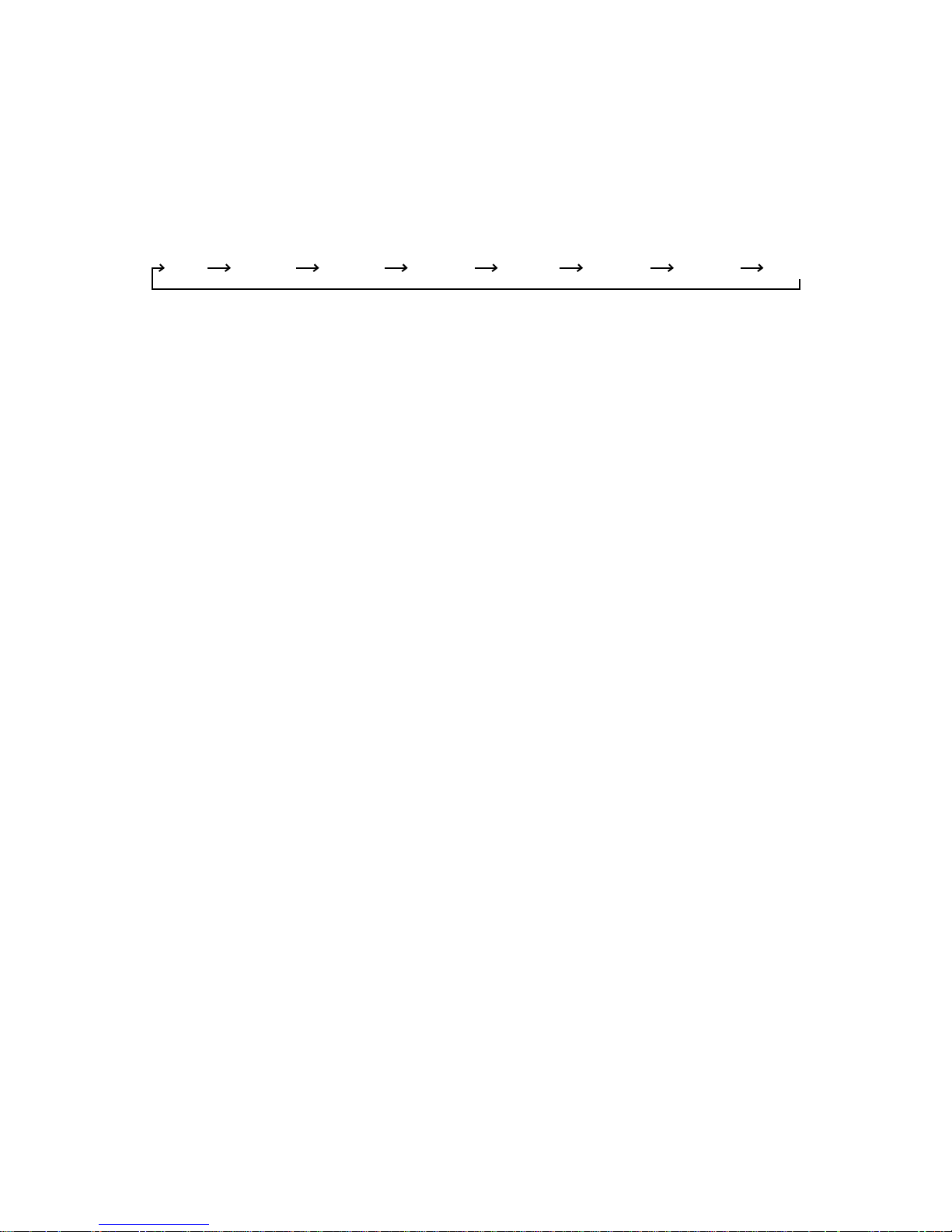
12. Off Timer Function
This function is to set the time of stopping the unit operation.
The procedure is as the following.
1st: Press the timer set button on the Remocon.
2nd:
The buzzer sounds and then the display window shows the Off-Time to be set as 1:00¡
...
¡ 7:00 ¡ 0:00.
- The Off-Time is shifted as the following by each press.
- If you select '0:00', the Off-Timer function will be cancelled.
- During Off-Timer Operation, if you repress the timer set button, the rest time will be displayed.
13. Alarm mode display / only displayed while operating.
CCHH 00
: The sensor for sensing room temperature is open or short.
CCHH 11
: The sensor for sensing piping temperature of evaporator is open or short.
14. Function for test operation.
This function shall be operated while the set not operating and start while set temperature set button(▼) down
and start/stop buttons pressing continuously for 3 seconds.
If you press start/stop button continuously for 3 seconds while set temp down button pressing once more test
operation and the set shall be stopped.
After test operation operating and 18 minutes, test operation and the set shall be stopped.
If you press start/stop button while test operation operating, test operation shall be stopped and the set shall
start.
When test operation operating, the display of
8888::8888
shall be shifted to tESt
4-way valve is always off when test operation.
Fan speed is high, air purifying system and auto air flow operations are off when test operation.
Regardless of outside temperature, the set operates when test operation.
All but start/stop and air purifying system buttons cannot be set.
15. Function of changing set temperature when re-operation after stop.
Heating operation is set to the previous set temperature when re-operation after stop. Cooling operation is set
to the previous set temperature when re-operation with start/stop button.
1.Operation mode.
Cooling/soft dry mode → Cooling mode
Heating mode → Heating mode
2. Setting the set temperature when cooling operation.
Room temperature > Set temperature: to be set to the previous set temperature.
Room temperature ≤ Set temperature
a) Room temperature ≥ 26°C: to be set to 24°C
b) 22°C ≤ Room temperature ≤ 25°C: to be set to 21°C
c) Room temperature ≤ 21°C:to be set to -1°C less than room temperature.
3. Setting the set temperature when heating operation.
Set the previous set temperature when stopped.
16. Auto Restart
In case the power comes on again a power failure, Auto Restarting Operation is the function to operate procedures automatically to the previous operating conditions.
– 23 –
1:00 2:00 3:00 4:00 5:00 6:00 7:00 0:00
– 24 –
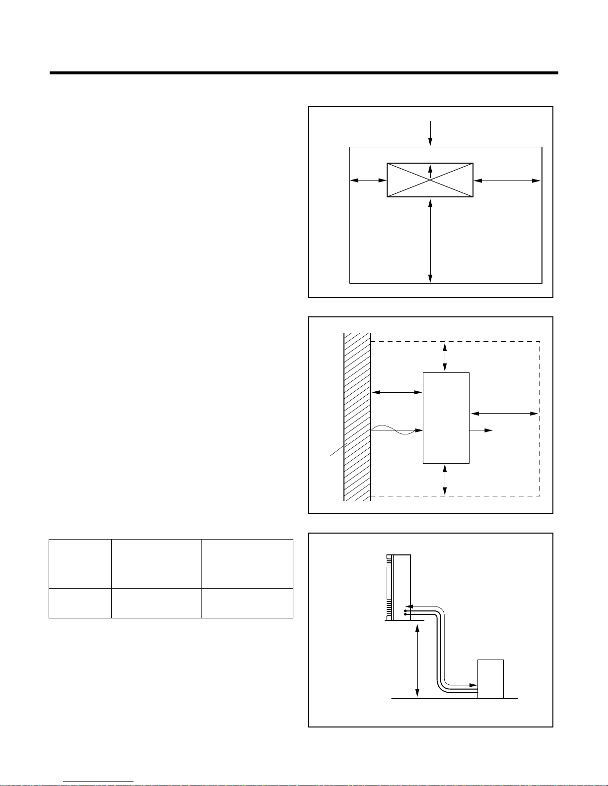
6.1 Installation of indoor , Outdoor Unit
1) Select the best location
¥LIndoor unit
• There should not be any heat source or steam near
the unit.
• There should not be any obstacles to prevent the air
circulation.
• The place where air circulation in the room will be
good.
• The place where drainage can be easily obtained.
• The place where noise prevention is taken into consideration.
• Do not install the unit near the door way.
• Ensure the space indicated by arrows from the wall,
ceiling, fence, or the obstacles.
¥MOutdoor unit
• If an awning is built over the unit to prevent direct
sunlight or rain exposure, be careful that heat radiation from the condenser is not restricted.
• There should not be any animals or plants which
could be affected by discharged hot air.
• Ensure the space indicated by arrows from the wall,
ceiling, fence, or other obstacles.
¥NPiping length and the elevation.
6. INSTALLATION
MODEL
MAX. Piping
length
A (m)
5HP 30 25
MAX.
elevation
B (m)
A
B
Indoor unit
Outdoor unit
Wall
More
than
50cm
More than
50cm
More than
50cm
More than
100cm
Outdoor
unit
5cm
5cm
40cm
100cm
Indoor unit
 Loading...