

LG LMU540HV Installation manual

P/NO : MFL67206502
INSTALLATION MANUAL
AIR CONDITIONER
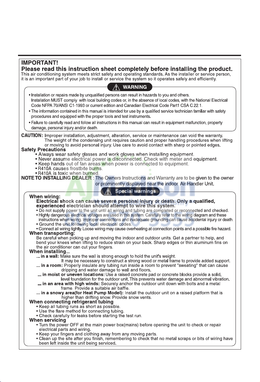
• Please read this installation manual completely before installing the product.
• Installation work must be performed in accordance with the national wiring
standards by authorized personnel only.
• Please retain this installation manual for future reference after reading it
thoroughly.
TYPE : Multi Type
http://www.lghvac.com
www.lg.com
ENGLISH FRANÇAIS ESPAÑOL
FLEX MULTI SPLIT INSTALLATION
INSTRUCTIONS

Installation Manual 3
Multi Air Conditioner Installation Manual
TABLE OF CONTENTS
Installation Parts Provided ...................................................4
Product Introduction .............................................................5
Indoor Unit.........................................................................5
Outdoor Unit ......................................................................5
Safety Precautions ................................................................6
Installation of Indoor, Outdoor Unit .....................................9
Select the best location ....................................................9
Seaside Applications and Installation ..............................11
Piping length and elevation .............................................12
Installation............................................................................14
Connecting the piping......................................................14
How To Fix.......................................................................18
Wiring Connection ...........................................................19
Conduit connection..........................................................19
Ceiling dimension and hanging bolt location ...................20
How to Fix .......................................................................21
Wiring Connection ...........................................................21
Conduit connection..........................................................21
Installation of wired Remote Controller ...........................23
Wired remote controller switch information .....................24
Trial Operation.................................................................25
Celsius/Fahrenheit Switching ..........................................26
Setting the Central-Control Address................................27
ESP Function ..................................................................28
Ceiling dimension and hanging bolt location ...................29
Wiring Connection ...........................................................30
Conduit connection..........................................................30
Installation of Wired Remote Controller(Optional)...........31
Installation of Decorative Panel.......................................33
Drain Piping.....................................................................35
Flaring Work and Connection of Piping ............................38
Flaring work.....................................................................38
Connection of piping - Outdoor .......................................39
Installation .......................................................................42
Installation of The Main Unit............................................43
Connecting the Cable between Indoor Unit, Distributor
Unit and Outdoor Unit .........................................................44
Connect the cable to the Indoor unit. ..............................44
Connect the cable to the Distributor unit .........................45
Connect the cable to the Outdoor unit.............................46
Connection method of the connecting cable(Example)...48
Checking the Drainage, Insulating the Pipe and Special
Piping Applications .............................................................49
Checking the drainage ....................................................49
Insulating the Pipe and Special Piping Applications........49
Long Pipe Setting ................................................................50
Air Purging and Evacuation................................................51
Leak Checking.................................................................51
Evacuation.......................................................................52
Charging ...............................................................................53
Combination indoor units ...................................................55
o Level gauge
o Screw driver
o Electric drill
o Hole core drill (ø50mm)
o Flaring tool set
o Specified torque wrenches
1.8kg.m, 4.2kg.m, 5.5kg.m, 6.6kg.m
(different depending on model No.)
o Adjustable wrench
o A glass of water
o Screw driver
o Hexagonal wrench(4mm)
o Refrigerant Gas Leak Detector
o Vacuum pump
o Gauge manifold
o Owner's manual
o Thermometer
o Remote Control Holder
Installation Requirements
Required Tools
ENGLISH
4 Multi Air Conditioner
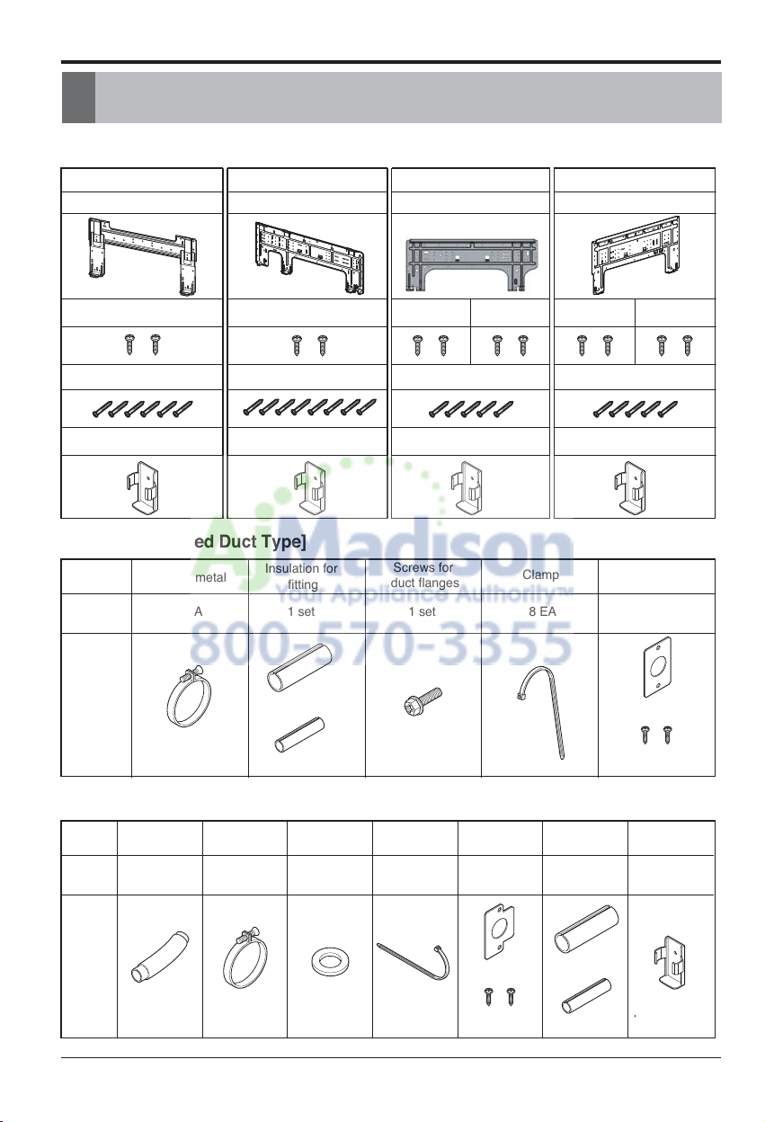
Installation Parts Provided
Installation Parts Provided
[Standard / Standard Libero / Artcool Mirror]
Type 1 Type 2
Installation plate Installation plate
Type 3 Type 4
Installation plate Installation plate
Type "B" screw Type "B" screw
Type "A" screw Type "A" screw
Remote control holderRemote control holder
[Ceiling Concealed Duct Type]
Name
Quantity
Shape
Clamp metal
1 EA
Insulation for
fitting
1 set
for gas pipe
for liquid pipe
[Ceiling Cassette Type]
Name
Quantity
Drain hose
1 EA
Clamp metal
1 EA
Washer for
hanging backet
8 EA
Type "B" screw Type "C" screw Type "B" screw Type "C" screw
Type “A” screw Type “A” screw
Remote control holderRemote control holder
Screws for
duct flanges
1 set
Clamp
8 EA 1 EA
Conduit
Bracket
Clamp
8 EA
Insulation for Remote
1 SET 1 EA
Conduit
Bracket
1 EA
Conduit Bracket
Screw(M4) 2EA
control holderfitting
Shape
Conduit Bracket
Screw(M4) 2EA
for gas pipe
for liquid pipe
Installation Manual 5
ENGLISH
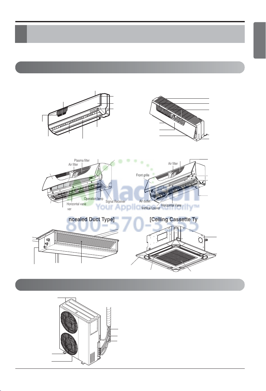
Product Introduction
Here is a brief introduction of the indoor and outdoor units. Please see the information specific to
your indoor unit type.
Product Introduction
more than
more than
30 cm
(11.8 inch)
more than
30 cm
(1
1.8 inch)
Air Intake
(side, rear)
Connection pipe
Drain hose
Connecting wire
Control cover
more than 30 cm
(11.8 inch)
Signal receiver
Front panel
Air discharge
ON/OFF button
Power cord
Plasma filter
Air inlet
Air filter
Air inlet
Plasma filter (Optional)
Air filter
Air outlet
Front grille
ON/OFF button
Signal
receiver
Grille tab
Flap
(Horizontal blade)
Louvers
(Vertical blades)
Cabinet
Air Discharge
Air Inlet
Signal receiver
Front Panel
Air outlet vents
Air Inlet
[Standard Type]
[Ceiling Concealed Duct Type]
[Standard Libero Type]
[Artcool Mirror Type]
[Ceiling Cassette Type]
Operation lamp
Signal Receiver
ON/OFF button
Air inlet
Plasma filter
Air filter
Front grille
Vertical louver
Air outlet
Horizontal vaneHorizontal vaneHorizontal vane
Air inlet
Front grille
On/ Off button
Signal receiver
Operation lamp
Plasma filter
Air filter
[Artcool Libero Type]
Air outlet
Vertical Louver
Horizontal Vane
30 cm
Air outlet vents
Base plate
Connection pipe
Drain hose
Connecting wire
Air intake vents
Horizontal vane
Indoor Unit
Outdoor Unit
h The figure can be changed according to model.
6 Multi Air Conditioner
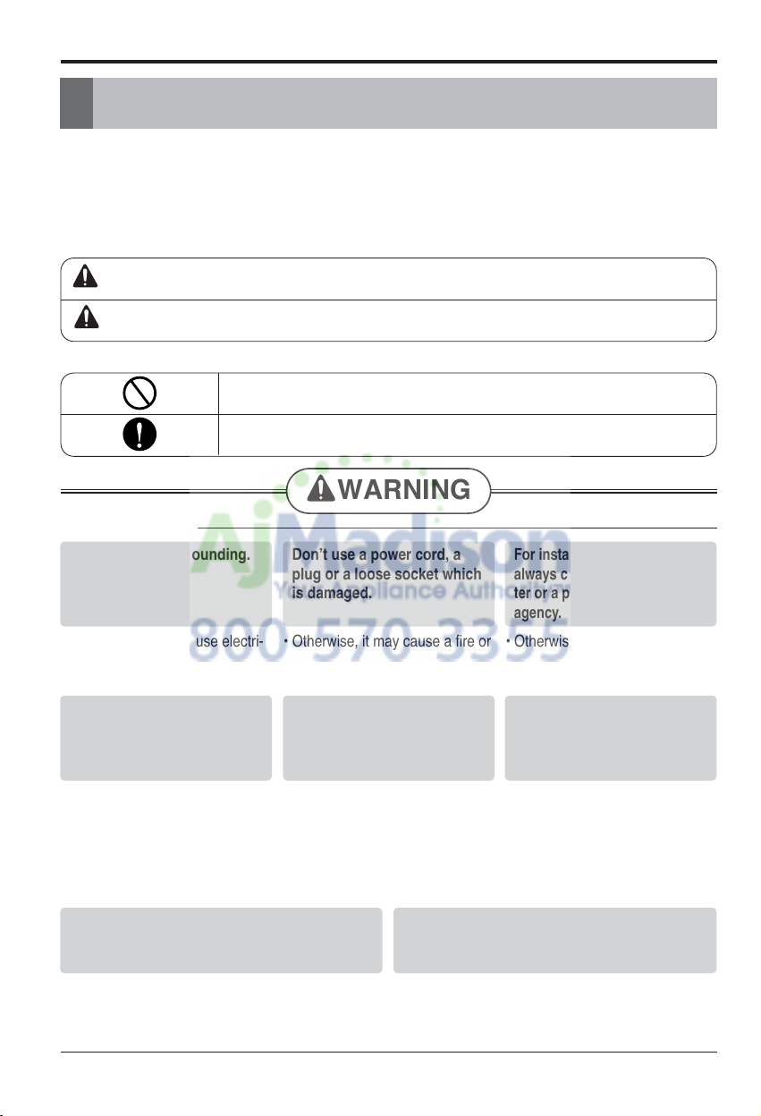
Safety Precautions
To prevent the injury of the user or other people and property damage, the following instructions
must be followed.
n Be sure to read before installing the air conditioner.
n Be sure to observe the cautions specified here as they include important items related to safety.
n Incorrect operation due to ignoring instruction will cause harm or damage. The seriousness is
classified by the following indications.
n The meanings of the symbols used in this manual are as shown below.
WARNING
CAUTION
This symbol indicates the possibility of death or serious injury.
This symbol indicates the possibility of injury or damage to properties only.
WARNING
n Installation
Be sure not to do.
Be sure to follow the instruction.
Safety Precautions
Always perform grounding.
• Otherwise, it may cause electri-
cal shock.
Donʼt use a power cord, a
plug or a loose socket which
is damaged.
• Otherwise, it may cause a fire or
electrical shock.
For installation of the product,
always contact the service center or a professional installation
agency.
• Otherwise, it may cause a fire,
electrical shock, explosion or injury.
Securely attach the electrical
part cover to the indoor unit
and the service panel to the
outdoor unit.
• If the electrical part cover of the
indoor unit and the service panel
of the outdoor unit are not attached securely, it could result in
a fire or electric shock due to
dust, water, etc.
Always install an air leakage
breaker and a dedicated
switching board.
• No installation may cause a fire
and electrical shock.
Do not keep or use flammable
gases or combustibles near
the air conditioner.
• Otherwise, it may cause a fire or
the failure of product.
Ensure that an installation frame of the outdoor unit is not damaged due to use for a long
time.
• It may cause injury or an accident.
Do not disassemble or repair the product randomly.
• It will cause a fire or electrical shock.
Installation Manual 7
ENGLISH
Safety Precautions
Do not install the product at a place that there
is concern of falling down.
• Otherwise, it may result in personal injury.
Use caution when unpacking and installing.
• Sharp edges may cause injury.
Take the power plug out if
necessary, holding the head
of the plug and do not touch
it with wet hands.
• Otherwise, it may cause a fire
or electrical shock.
Do not use the power cord
near the heating tools.
• Otherwise, it may cause a fire
and electrical shock.
Do not open the suction
inlet of the indoor/outdoor
unit during operation.
• Otherwise, it may electrical
shock and failure.
Do not allow water to run
into electrical parts.
• Otherwise, it may cause the
failure of machine or electrical
shock.
Hold the plug by the head
when taking it out.
• It may cause electric shock
and damage.
Never touch the metal parts
of the unit when removing
the filter.
• They are sharp and may
cause injury.
Do not step on the
indoor/outdoor unit and do
not put anything on it.
• It may cause an injury through
dropping of the unit or falling
down.
Do not place a heavy object
on the power cord.
• Otherwise, it may cause a fire
or electrical shock.
When the product is submerged into water, always
contact the service center.
• Otherwise, it may cause a fire
or electrical shock.
Do not share the outlet with
other appliances.
•
It will cause an electric shock or
a fire due to heat generation.
Do not use the damaged
power cord.
• Otherwise, it may cause a fire
or electrical shock.
Do not modify or extend the
power cord randomly.
• Otherwise, it may cause a fire
or electrical shock.
Take care so that the power
cord may not be pulled during operation.
• Otherwise, it may cause a fire
or electrical shock.
Unplug the unit if strange
sounds, smell, or smoke
comes from it.
• Otherwise, it may cause elec-
trical shock or a fire.
Keep the flames away.
• Otherwise, it may cause a fire.
Take care so that children may not step on the outdoor unit.
• Otherwise, children may be seriously injured due to falling down.
n Operation
Use a vacuum pump or Inert (nitrogen) gas when doing leakage test or air purge. Do not compress air
or Oxygen and Do not use Flammable gases. Otherwise, it may cause fire or explosion.
•
There is the risk of death, injury, fire or explosion.
8 Multi Air Conditioner
Safety Precautions
CAUTION
n Installation
Install the drain hose to ensure that drain
can be securely done.
• Otherwise, it may cause water leakage.
Install the product so that the noise or hot
wind from the outdoor unit may not cause
any damage to the neighbors.
• Otherwise, it may cause dispute with the neighbors.
Always inspect gas leakage after the installation and repair of product.
• Otherwise, it may cause the failure of product.
Keep level parallel in installing the product.
• Otherwise, it may cause vibration or water leakage.
Avoid excessive cooling and perform ventilation sometimes.
• Otherwise, it may do harm to your health.
Use a soft cloth to clean. Do not use wax,
thinner, or a strong detergent.
• The appearance of the air conditioner may deteriorate, change color, or develop surface
flaws.
Do not use an appliance for special purposes
such as preserving animals vegetables, preci-
sion machine, or art articles.
• Otherwise, it may damage your properties.
Do not place obstacles around the flow inlet
or outlet.
• Otherwise, it may cause the failure of appliance
or an accident.
n Operation
Installation Manual 9
ENGLISH
Installation of Indoor, Outdoor Unit
Installation of Indoor, Outdoor Unit
Read completely, then follow step by step.
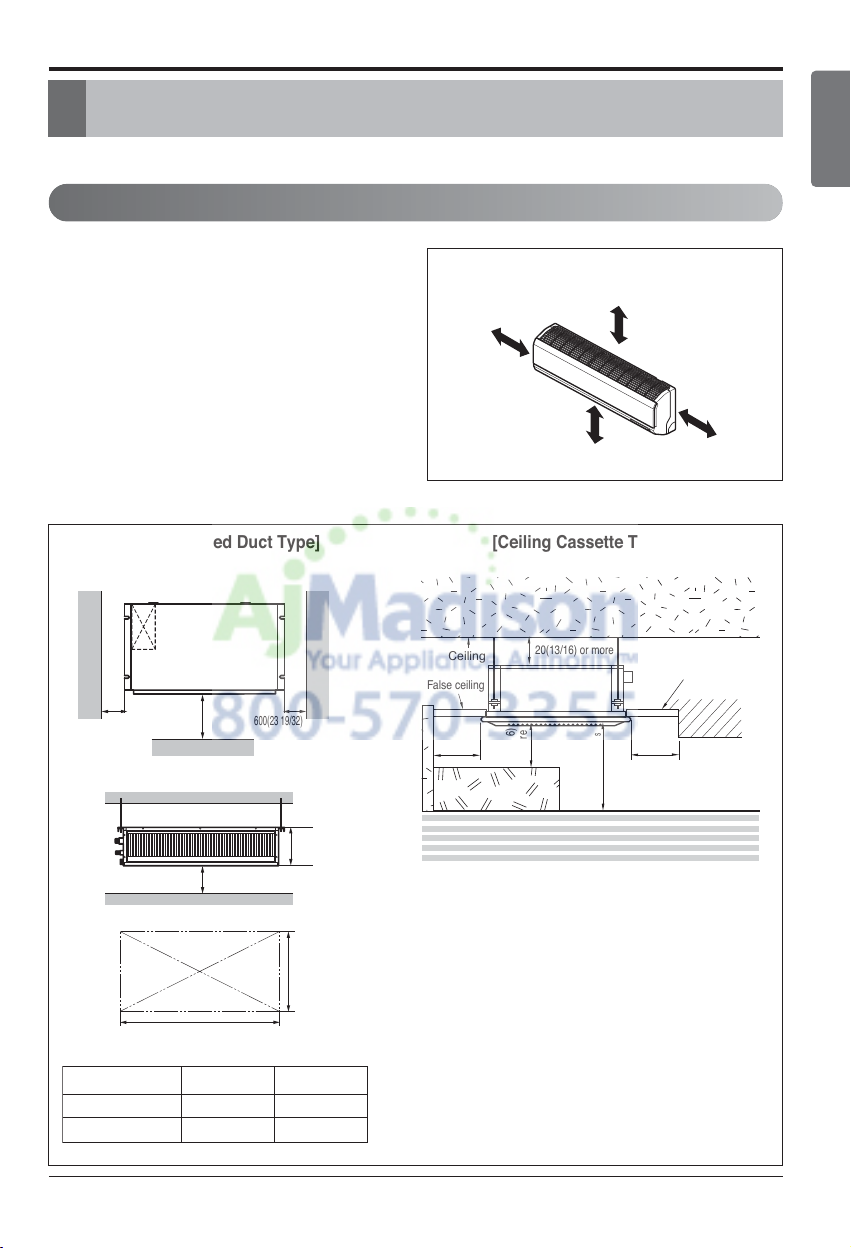
Indoor unit
1. Do not have any heat or steam near the unit.
2. Select a place where there are no obstacles
in front of the unit.
3. Make sure that condensation drainage can be
conveniently routed away.
4. Do not install near a doorway.
5. Ensure the unit is unobstructed, allow proper
space on all sides according to the arrows
and distance measurements in the figures.
6. Use a Metal Detector or Metal Scanner to locate studs to prevent unnecessary damage to
the wall.
Select the best location
Top view
Front view
600(23 19/32)
600(23 19/32)
7 5/16
Front
1000(39 3/8)
H=13/16 or more
A
B
Capacity(Btu/h class)
AB
9/12k 600(23 5/8) 900(35 15/32)
18k 600(23 5/8) 1100(43 5/16)
Unit:mm(inch)
Ceiling
False ceiling
False ceiling
20(13/16) or more
1500
(59 1/16)
or more
1500(59 1/16) or
more
Above 2500(98 7/16)
3300(129 15/16) or less
1500(59 1/16)or
more
Floor
[Ceiling Concealed Duct Type] [Ceiling Cassette Type]
More than 200(7 7/8)
More than
2300(90 9/16)
More than
100(3 15/16)
More than
100(3 15/16)
Unit:mm(inch)
[Standard/Standard Libero/Artcool Mirror/Artcool Libero Type]
10 Multi Air Conditioner
Installation of Indoor, Outdoor Unit
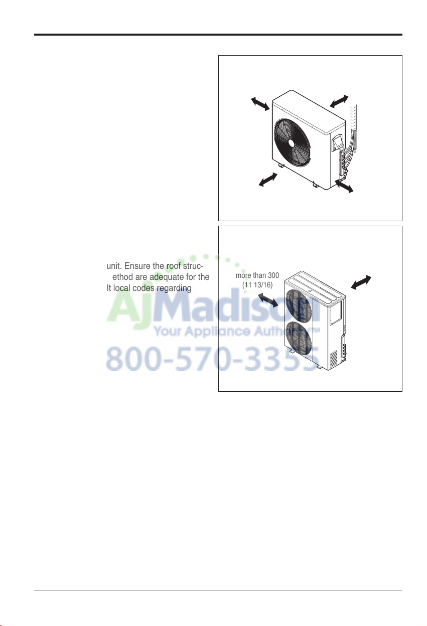
Outdoor unit
1. If an awning is built over the unit to prevent direct sunlight or rain exposure, make sure that
heat radiation from the condenser is not restricted.
2. Ensure the unit is unobstructed, allow proper
space on all sides according to the arrows
and distance measurements in the figures.
3. Do not place animals and plants in the path of
the warm air.
4. Take the air conditioner weight into account
and select a place where noise and vibration
are minimum.
5.
Select a place so that the warm air and sound
from the air conditioner does not disturb
neighbors.
Rooftop Installations:
If the outdoor unit is installed on a roof structure,
be sure to level the unit. Ensure the roof struc-
ture and anchoring method are adequate for the
unit location. Consult local codes regarding
rooftop mounting.
more than 700
(27 9/16)
more than 300
(11 13/16)
more than 300
(11 13/16)
more than 600
(23 21/32)
more than 300
(11 13/16)
more than 300
(11 13/16)
Unit:mm(inch)
Unit:mm(inch)
Installation Manual 11
ENGLISH
Installation of Indoor, Outdoor Unit
Seaside Applications and Installation
Sea wind Sea wind
1. Selecting the location(Outdoor Unit)
1.
Air conditioners should not be installed in areas where corrosive gases, such as acid or alkaline gas, are
produced.
2. Do not install the product where it could be exposed to sea wind (salty wind) directly. It can result
corrosion on the product. Corrosion, particularly on the condenser and evaporator fins, could
cause product malfunction or inefficient performance.
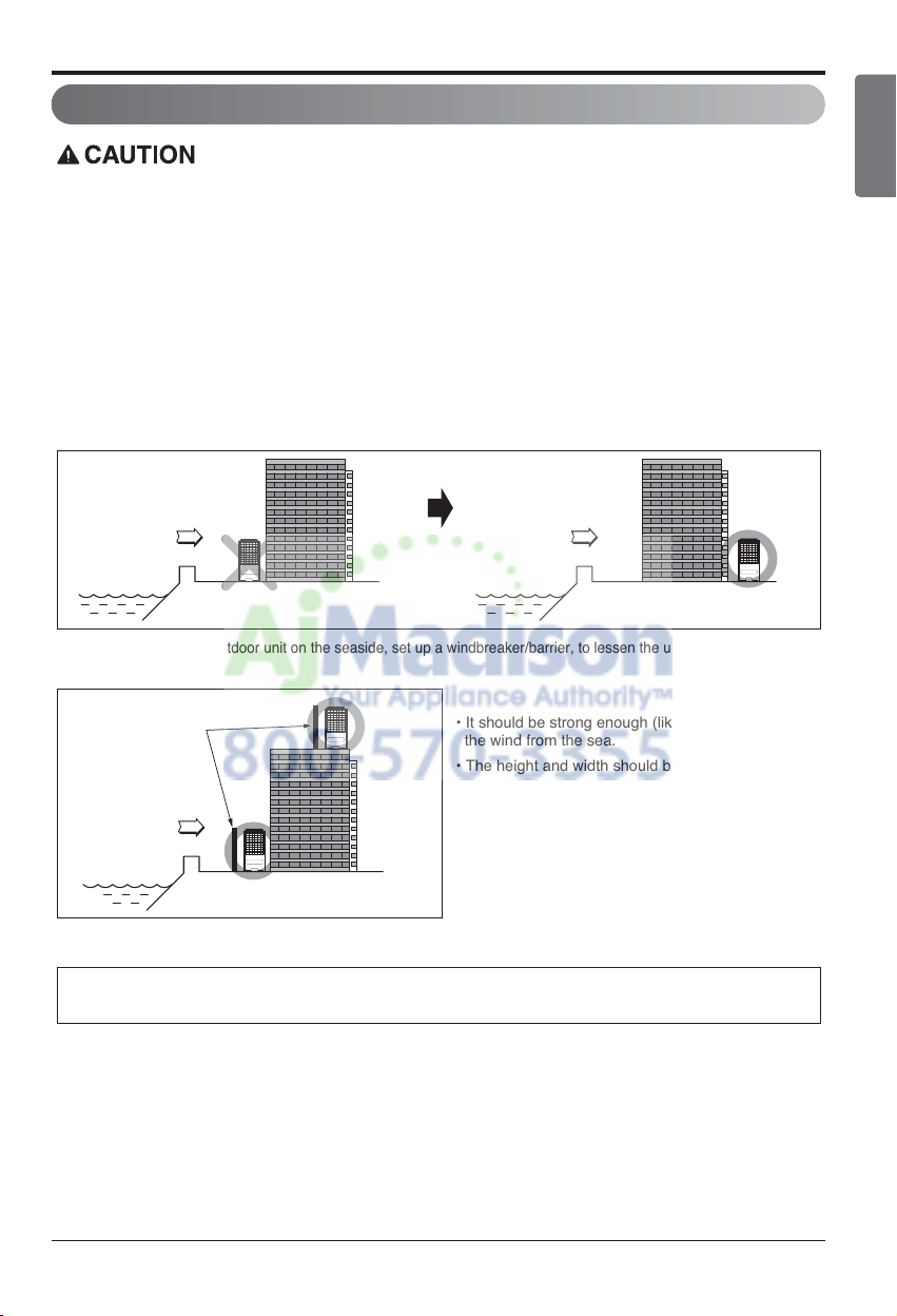
3. If outdoor unit is installed close to the seaside, it should avoid direct exposure to the sea wind.
1) If the outdoor unit is to be installed close to the seaside, direct exposure to the sea wind should be avoided.
Install the outdoor unit on the opposite side of the sea wind direction.
2)
In case, to install the outdoor unit on the seaside, set up a windbreaker/barrier, to lessen the unit's exposure to sea air
Windbreaker/Barrier
Sea wind
3) Select a well-drained place.
Periodic ( more than once/year ) cleaning of the dust or salt particles stuck on the heat exchanger
using water is recommended.
• It should be strong enough (like concrete) to obstruct
the wind from the sea.
• The height and width should be more than 150% of
the outdoor unit.
• A minimum of 70cm (27 1/16 inches)
of space between outdoor unit and the windbreak
for easy air flow.
12 Multi Air Conditioner
Installation of Indoor, Outdoor Unit
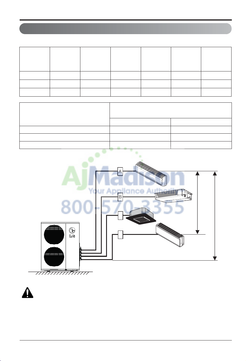
Multi Piping Type
Piping length and elevation
CAUTION: Capacity is based on standard length and maximum allowance
length is on the basis of reliability.
Unit : m(ft)
18k 50(164) 25(82) 3(10) 15(49) 7.5(25) 24k
24k 75(246) 25(82) 3(10) 15(49) 7.5(25) 33k
36k 75(246) 25(82) 3(10) 15(49) 7.5(25) 48k
Outdoor Unit
Capacity
(Btu/h class)
Max total length
of all pipes
(A+B)/(A+B+C)/
(A+B+C+D)
Max length of
each pipe
(A/B/C/D)
Min length of
each pipe
(A/B/C/D)
Max Elevation
between each
indoor unit and
outdoor unit (h1)
Max elevation
between indoor
units (h2)
Max.Combination
of Indoor unit
(Btu/h class)
Indoor unit Capacity (Btu/h class)
Pipe Diameter
Unit : mm(inch)
Gas Liquid
9k 9.52(3/8) 6.35(1/4)
12k 9.52(3/8) 6.35(1/4)
18k 12.7(1/2) 6.35(1/4)
A
B
h2
C
D
h1
Installation Manual 13
ENGLISH
Installation of Indoor, Outdoor Unit
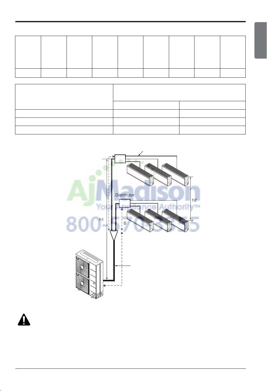
Distributor Piping Type
h1
C
Branch Pipe
Main Pipe
Distributor
Distributor
A
B
h2
CAUTION: Capacity is based on standard length and maximum allowance
length is on the basis of reliability.
Unit : m(ft)
Outdoor Unit
Capacity
(Btu/h class)
Max total length
of all pipes
(Main + Branch
pipes)
Max length
of
Main pipe
(A+B+C)
Max length
of
Branch
pipes
Max length
of each
Branch pipe
Min length of
each pipe
(Main /
Branch
pipes)
Max Elevation
Between each
indoor unit and
outdoor unit
(h1)
Max Eleva-
tion
Between in-
door
(h2)
Max Combi-
nation
of indoor
unit
54k 145(476) 55(180) 90(295) 15(49) 3(10) 30(98) 15(49) 73k
Indoor unit Capacity (Btu/h class)
Pipe Diameter
Unit : mm(inch)
Gas Liquid
9k 9.52(3/8) 6.35(1/4)
12k 9.52(3/8) 6.35(1/4)
18k 12.7(1/2) 6.35(1/4)
14 Multi Air Conditioner
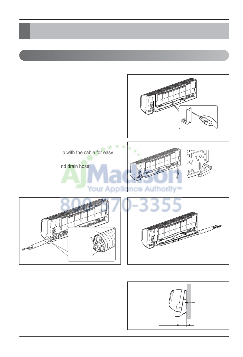
Installation
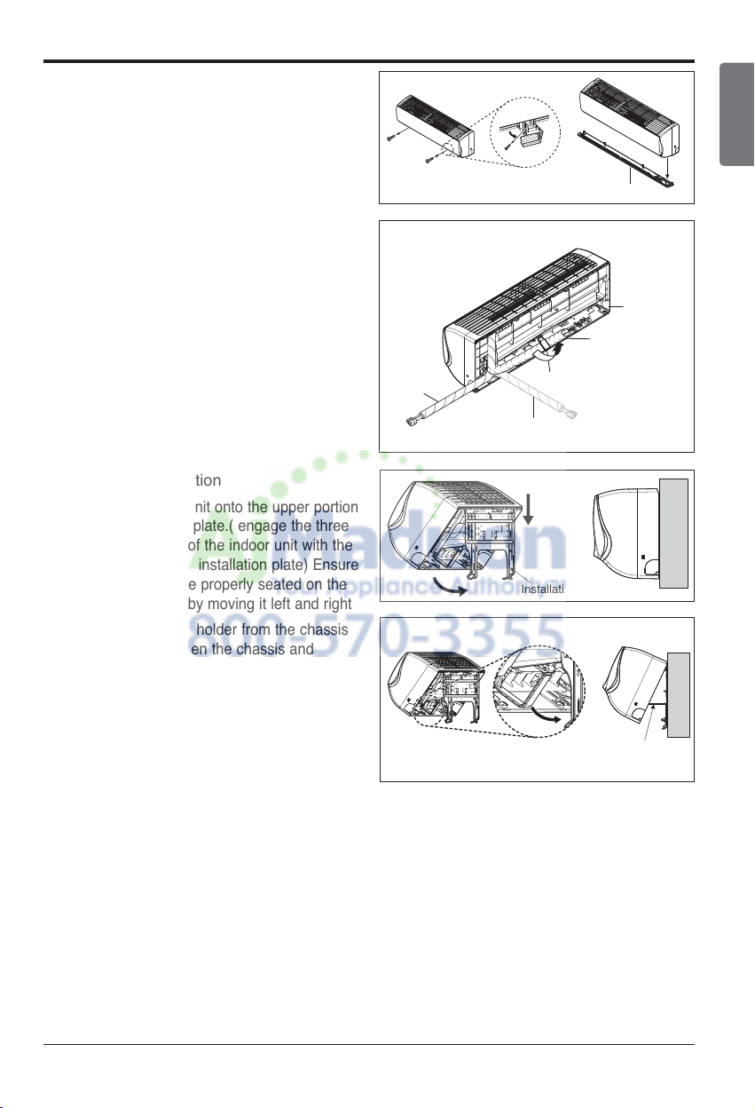
# Standard / Artcool Mirror Type
1. Prepare the indoor unit's piping and drain
hose for installation through the wall.
2. Remove the plastic tubing retainer(see the illustration on the right) and pull the tubing and
drain hose away from chassis.
3. Route the indoor tubing and the drain hose to
the required piping hole position.
4. Insert the piping, drain hose, and the connecting cable into the piping hole.
5.
Insert the connecting cable into the indoor unit.
• Don't connect the cable to the indoor unit.
• Make a small loop with the cable for easy
connection later.
6. Tape the tubing and drain hose.
7. Indoor unit installation
• Hang the indoor unit from the hooks at the
top of the installation plate.
• Insert the spacer etc. between the indoor
unit and the installation plate and separate
the bottom of the indoor unit from the wall.
Connecting
pipe
Tape
Drain hose
For right rear piping For left rear piping
Installation
Connecting the piping
[Standard / Standard Libero / Artcool Mirror Type]
Drain pipe
Indoor unit
Spacer
Installation plate
80(3 5/32)
Installation Manual 15
ENGLISH
Installation
# Standard Libero / Artcool Libero Type
1. Pull the screw cap at the bottom of the
indoor unit
2. Remove the chassis cover from the unit
by loosing screws
3. Pull back the tubing holder.
4. Remove pipe port cover and positioning
the tubing
5. Indoor unit installation
1) Hook the indoor unit onto the upper portion
of the installation plate.( engage the three
hooks at the top of the indoor unit with the
upper edge of the installation plate) Ensure
that the hooks are properly seated on the
installation plate by moving it left and right
2) Unlock the tubing holder from the chassis
and mount between the chassis and
installation plate in order to separate the
bottom side of the indoor unit from the wall
Indoor unit back side view
Right
Chassis cover
Pipe Port
Left
Tubing holder
Backwards
Installation plate
Tubing Holder
16 Multi Air Conditioner
Installation
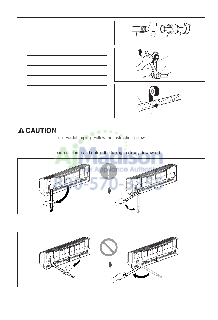
Connecting the piping to the indoor unit
and drain hose to drain pipe.
1. Align the center of the pipes and suffi-
ciently tighten the flare nut by hand.
2. Tighten the flare nut with a wrench.
3. Next, extend the indoor unit's drain hose.
Then attach the drain pipe.
Installation Information. For left piping. Follow the instruction below.
Good case
• Press on the upper side of clamp and unfold the tubing to slowly downward.
Bad case
• Bending the pipe from right to left may cause damage to the tubing.
Outside diameter Torque
mm inch N. m kgf.m lbf.ft
Ø6.35 1/4 14~18 1.4~1.8 10~13
Ø9.52 3/8 34~42 3.5~4.3 25~31
Ø12.7 1/2 49~61 5.0~6.2 36~45
Ø15.88 5/8 69~82 7.0~8.4 51~60
Ø19.05 3/4 100~120 10.0~12.2 73~88
Indoor unit tubing Flare nut Pipes
Open-end wrench (fixed)
Flare nut
Wrench
Indoor unit tubing
Drain pipe
Indoor unit drain hose
Vinyl tape(narrow)
Adhesive
Connection pipe
Installation Manual 17
ENGLISH
Installation
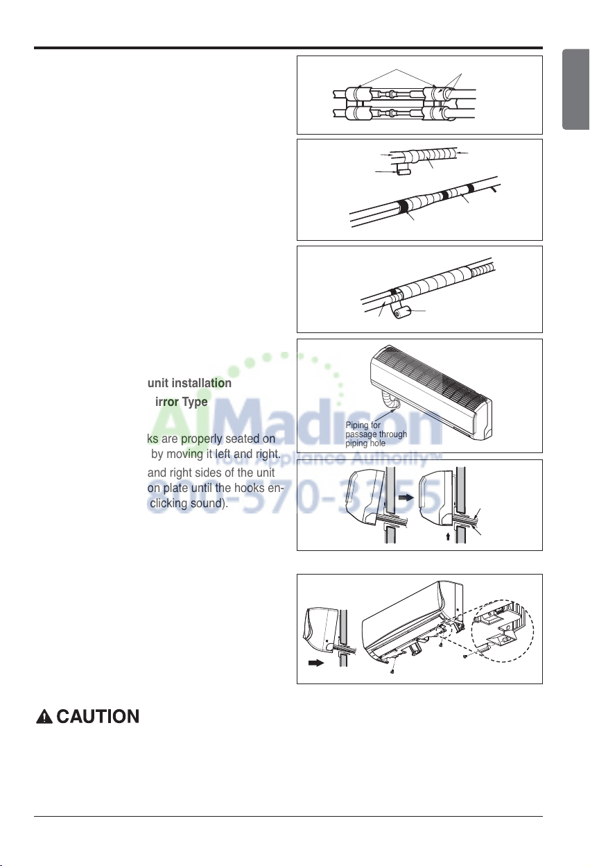
Wrap the insulation material around the connecting portion.
1. Overlap the connection pipe insulation and the
indoor unit pipe heat insulation material. Bind
them together with vinyl tape so that there is no
gap.
2. Wrap the area which accommodates the rear
piping housing section with vinyl tape.
3. Bundle the piping and drain hose together by
wrapping them with vinyl tape over the range
within which they fit into the rear piping housing
section.
Reroute the pipings and the drain hose across
the back of the chassis.
Finishing the indoor unit installation
# Standard / Artcool Mirror Type
1. Remove the spacer.
2. Ensure that the hooks are properly seated on
the installation plate by moving it left and right.
3. Press the lower left and right sides of the unit
against the installation plate until the hooks en-
gage into their slots(clicking sound).
# Standard Libero / Artcool Libero Type
1.
Mount the tubing holder in the original positon.
2.
Ensure that the hooks are properly seated on the
installation plate by moving it left and right.
3. Press the lower left and right sides of the unit
against the installation plate until the hooks
engage into their slots (clicking sound).
4.
Finish the assembly by screwing the unit to the
installation plate by using two pieces of type "C"
screws. And assemble a chassis cover.
If the split type Indoor unit is installed in a wall having hole or opening near by or back side of the
unit, then the air from other side of the wall can come inside the condition space through that hole /
opening. That air can cause unwanted dew / water droplet formation when it comes in contact with
body of the indoor unit. So all hole or opening on the wall must be blocked very well to avoid water
dropping from the body of the unit.
Plastic bands
Connection pipe
Vinyl tape (wide)
Drain hose
Piping for
passage through
piping hole
Insulation material
Wrap with vinyl tape
Vinyl tape(narrow)
Vinyl tape(wide)
Indoor unit pipe
Pipe
Connecting
Drain hose
Type 'C' screw
18 Multi Air Conditioner
Installation
The wall you select should be strong and solid enough to prevent vibration
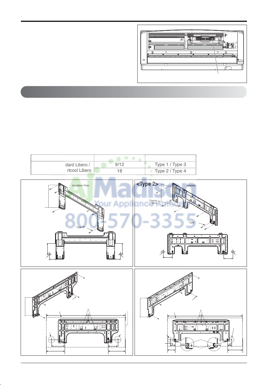
1. Mount the installation plate on the wall with
type "A" screws. If mounting the unit on a concrete wall, use anchor bolts.
• Mount the installation plate horizontally by aligning the centerline using a level.
2. Measure the wall and mark the centerline. It is also important to use caution concerning the location of the installation plate-routing of the wiring to power outlets is through the walls typically.
Drilling the hole through the wall for piping connections must be done safely.
How To Fix
Installation of filters
1) Detach two attached tapes from the plasma
filter.
Ø70
(2 3/4)
Ø70
(2 3/4)
110(4 11/32)
110
(4 11/32)
90
(3 17/32)
70
(2 3/4)
Chassis
Hook
Installation Plate
Type “A”
Left rear piping Right rear piping
Ø70
(2 3/4)
133(5 1/4)
Ø70
(2 3/4)
100(3 15/16)
Chassis
Hook
Installation Plate
Type “A”
Left rear piping Right rear piping
Ø70
(2 3/4)
133(5 1/4)
95(5 3/4)
217(8 17/32)
175(6 7/8)
442(17 13/32) 442(17 13/32)
Ø70
(2 3/4)
Installation Plate
Enganche
del chasis
Type "A" Screws
Right rear piping
Left rear piping
Installation Plate
Place a level on raised tab
Unit Outline
Ø70
(2 3/4)
Ø70
(2 3/4)
69(2 23/32)
56(2 7/32)
207(8 5/32)
105(4 1/8)
460(18 1/8) 570(22 7/16)
Installation Plate
Enganche
del chasis
Type "A" Screws
Left rear piping
Installation Plate
Place a level on raised tab
Unit Outline
Right
rear
piping
Measuring Tape
Hanger
Measuring Tape
<Type 1> <Type 2>
<Type 3> <Type 4>
Indoor Type
Capacity (kBtu/h)
Type
Standard / Standard Libero /
Artcool Mirror / Artcool Libero
9/12
Type 1 / Type 3
18
Type 2 / Type 4
Plasma Filter
 Loading...