

LG LMAB1240 Service Manual
MEASUREMENT OF MICROWAVE POWER OUTPUT
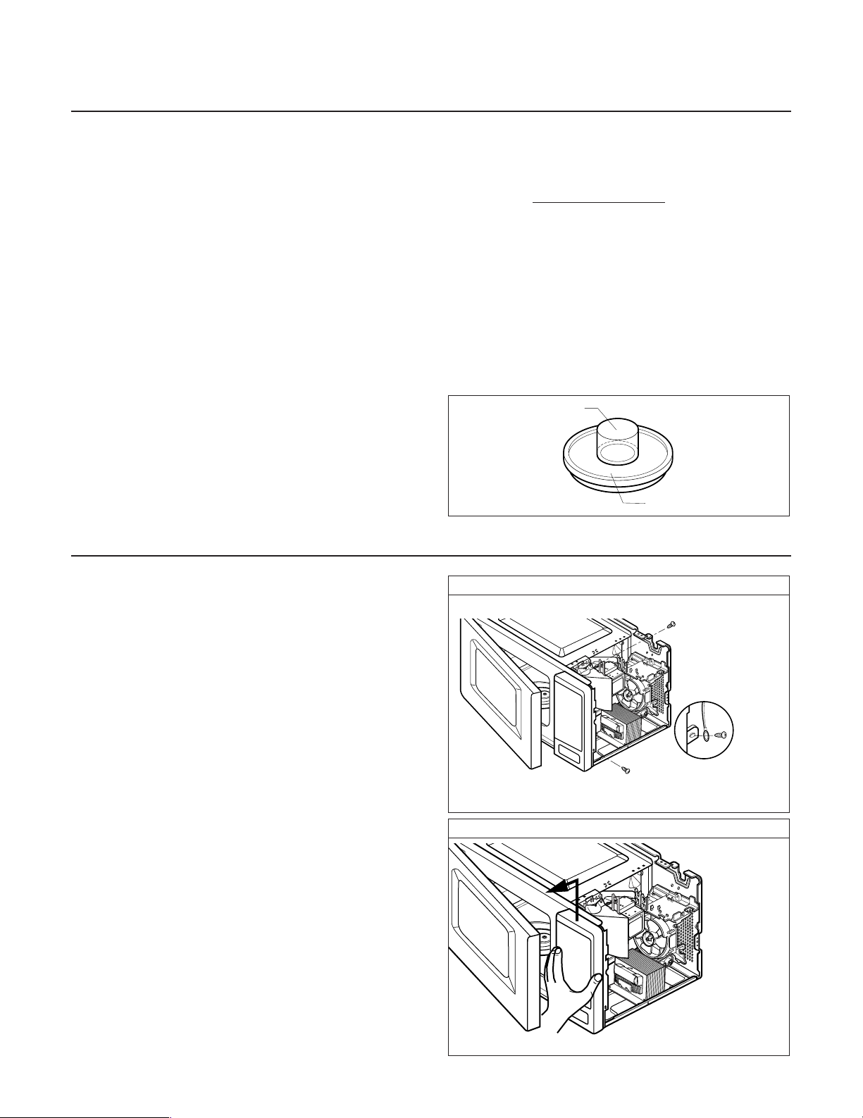
WATER LOAD
TURNTABLE
• Microwave power output measurement is made with
the microwave oven supplied at its rated voltage and
operated at its maximum microwave power setting with
a load of (1000 ± 5)g of potable water.
• The water is contained in a cylindrical borosilicate glass
vessel having a maximum material thickness of 3 mm
and an outside diameter of approximately 190mm.
• The oven and the empty vessel are at ambient
temperature prior to the start of the test.
• The initial temperature (T1) of the water is (10±2)°C. It
is measured immediately before the water is added to
the vessel. After addition of the water to the vessel,
the load is immediately placed on the center of the
turntable which is in the lowest position and the
microwave power switched on.
• The time T for the temperature of the water to rise by a
value ∆T of (10±2)° is measured, where T is the time in
seconds and ∆T is the temperature rise. The initial and
final water temperatures are selected so that the
maximum difference between the final water
temperature and the ambient temperature is 5°.
• The microwave power output P in watts is calculated
from the following formula:
is measured while the microwave generator is
operating at full power. Magnetron filament heat-up
time is not included. (about 3 sec)
• The water is stirred, to equalize temperature throughout
the vessel, prior to measuring the final water
temperature.
• Stirring devices and measuring instruments are
selected in order to minimize addition or removal of
heat.
DISASSEMBLY AND ADJUSTMENT
P =
4187 x (∆T)
T
A. OUTER CASE REMOVAL
1) Disconnect the power supply cord from the outlet.
2) Remove the screws from the rear of the case.
The outer case must be moved backward to be lifted
off.
B. POWER SUPPLY CORD
1) Remove the outer case.
2) Disconnect two terminals and remove one screw of the
ground terminal.
C. CONTROL PANEL ASSEMBLY
1) Open the door.
2) Disconnect the lead wire from RELAY (RY2) of the
PCB SUB ASSEMBLY.
3) Disconnect the leadwire from connector (CN1) of the
PCB SUB ASSEMBLY.
4) Remove screw which hold the controller assembly to
the cavity.
5) Lift up and pull out control panel assembly carefully
from the cavity.
CAUTION: DISCHARGE THE HIGH VOLTAGE
CAPACITOR BEFORE SERVICING
(refer to page 2-1)
Remove the screw
securing
screw
ground
screw
Lift up and pull out control panel
5-3
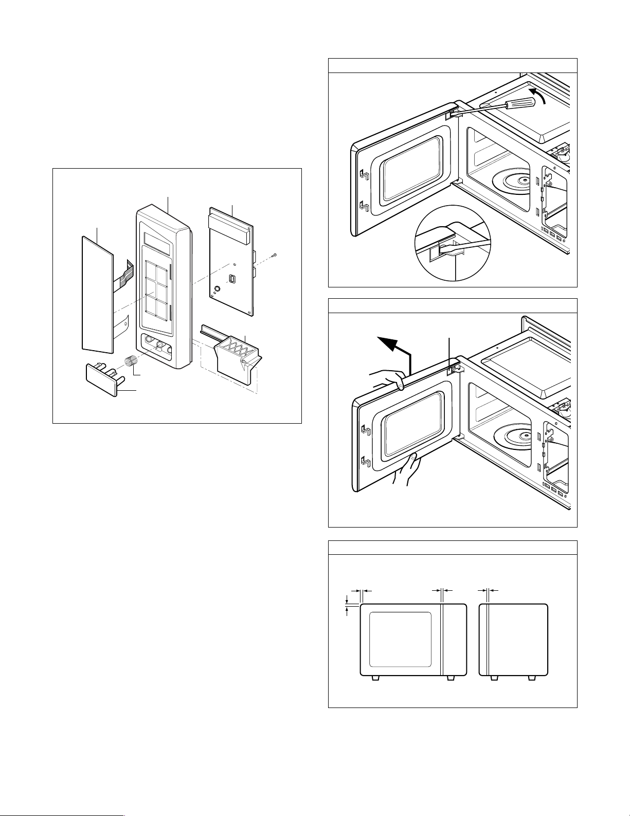
D. PCB ASSEMBLY REMOVAL
Control Panel
Button Spring
Door Open Button
Key Membrance
PCB Sub Asm
Release
Lever
1) Remove the control panel assembly from the
cavity. (Refer to control panel assembly removal
on previous page.)
2) Remove screws which hold the PCB SUB
ASSEMBLY to the control panel.
3) Disconnect the flat cable from the PCB SUB
ASSEMBLY and take off the PCB SUB ASSEMBLY.
Remove choke cover
Remove door
Door seal plate
E. DOOR ASSEMBLY REMOVAL
1) Open the door.
2) Remove the choke cover very carefully with a flat-blade
screwdriver.
CAUTION: Be careful not to damage door seal plate
3) Lift up and push the door.
NOTE:
1. After replacing the door, be sure to check that the
primary switch, monitor switch, and secondary switch
operate normally.
2. After replacing the door, check for microwave energy
leakage with a survey meter. Microwave energy must
be below the limit of 4 mW/cm2. (with a 275 ml water
load)
3. When mounting the door assembly to the oven
assembly, be sure to adjust the door assembly parallel
to the chassis. Also, adjust so the door has no play
between the inner door surface and oven frame
assembly. If the door assembly is not mounted
properly, microwaves may leak from the clearance
between the door and the oven.
by screwdriver.
Spacer
5-4
 Loading...