

LG LM-2422C2L, LM-2422A2L/A3L, LM-3622A2L, LM-3625C3L/A3L, LM-3626A3L Service Manual
...
Multi Type Room
Air Conditioner
SERVICE MANUAL
MODEL: LM-2422C2L
LM-2422A2L/A3L
LM-3620C2L/C2M/A2L
LM-3622A2L
LM-3625C3L/A3L
LM-3626A3L
LM-4822C3L
LM-4822A3L

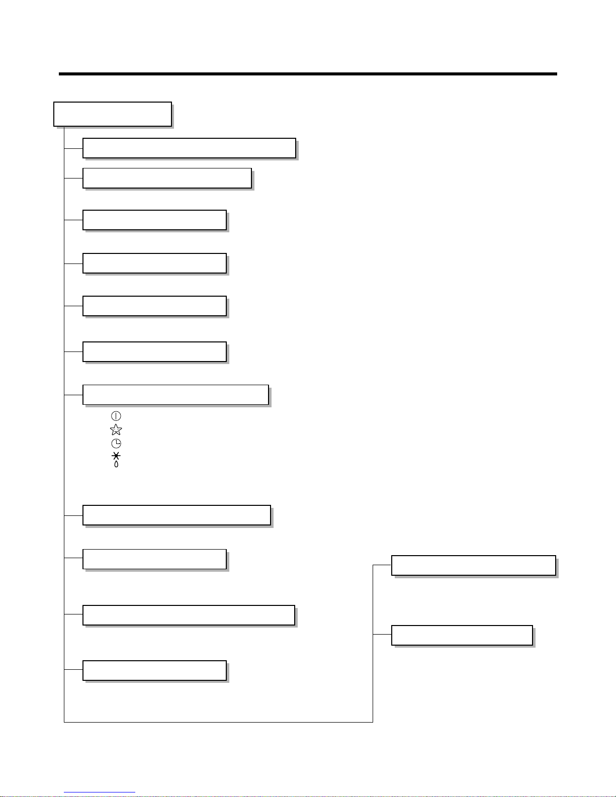
Functions...................................................................................................................................... 3
Product Specifications................................................................................................................ 5
Dimensions................................................................................................................................... 9
Refrigeration Cycle Diagram..................................................................................................... 13
Wiring Diagram .......................................................................................................................... 17
Operation Details ....................................................................................................................... 20
Display Function........................................................................................................................ 27
Self-diagnosis Function ............................................................................................................ 27
Installation.................................................................................................................................. 28
Operation.................................................................................................................................... 42
Disassembly of the parts (Indoor Unit).................................................................................... 44
2-way, 3-way Valve..................................................................................................................... 46
Cycle Troubleshooting Guide ....................................................................................................50
Electronic Parts Troubleshooting Guide.................................................................................. 51
Electronic Control Device ......................................................................................................... 58
Schematic Diagram.................................................................................................................... 61
Exploded View and Replacement Parts List............................................................................ 66
- 2 -
Contents
- 3 -
Functions
• Room temperature sensor. (THERMISTOR)
• Maintains the room temperature in accordance with the Setting Temp.
• Indoor fan is delayed for 5 seconds at the starting.
• Restarting is inhibited for approx. 3 minutes.
• High, Med, Low, Chaos
--- Lights up in operation
--- Lights up in Sleep Mode
--- Lights up in Timer Mode
--- Lights up in Deice Mode(for Heat pump model)
--- Lights up in Compressor operation(for Cooling model)
• Intermittent operation of fan at low speed.
• The fan is switched to low(Cooling), med(Heating) speed.
• The unit will be stopped after 1, 2, 3, 4, 5, 6, 7 hours.
• The fan is switched to intermittent or irregular operation
•
The fan speed is automatically switched from high to low speed.
• The louver can be set at the desired position or swing
up and down automatically.
Indoor Unit
Operation ON/OFF by Remote controller
Sensing the Room Temperature
Room temperature control
Starting Current Control
Time Delay Safety Control
Indoor Fan Speed Control
Operation indication Lamps (LED)
OUT
DOOR
Health Dehumidification Operation
• Both the indoor and outdoor fan
stops during deicing.
• Hot start after deice ends.
• The indoor fan stops until the
evaporator piping temperature will be
reached at 22°C.
Sleep Mode Auto Control
Natural Air Control by CHAOS Logic
Airflow Direction Control
Deice (defrost) control (Heating)
Hot-start Control (Heating)
- 4 -
Healthy Dehumidification Operation Mode.
( )
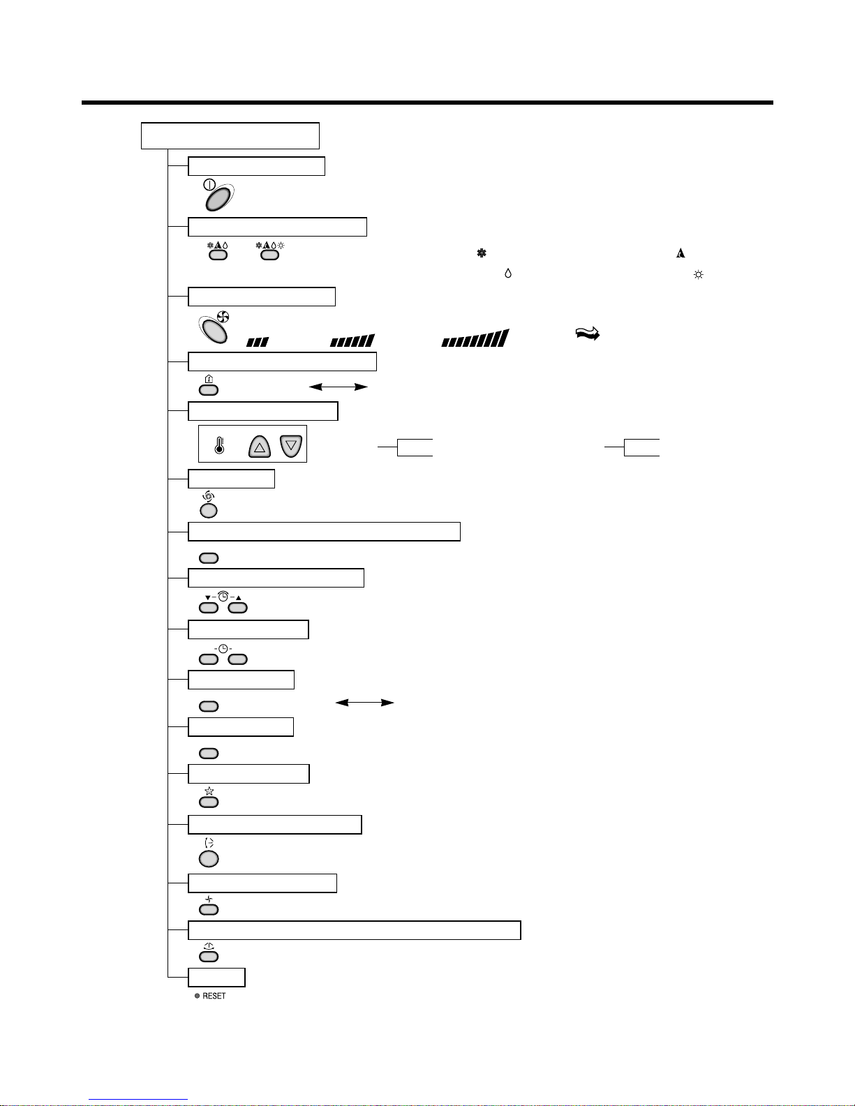
Remote Controller
Operation ON/OFF
Reset
Operation Mode Selection
Temperature Setting
Timer Selection
Timer Setting
JET COOL
Timer Cancel
Sleep Operation
Airflow Direction Control
(Cooling
model only)
(Heating
model only)
TEMPERATURE
LOW HIGH
Cooling Operation Mode.( )
Heating Operation Mode.( )
Auto Operation Mode.( )
Fan Operation Mode
Horizontal Airflow Direction Control Button(Option)
Room, Temperature Display
Setting the Time or Timer
PLASMA(Option)/NEGATIVE ION(Option)
ON OFF
SET
PLASMA
CANCEL
Fan Speed Selection
(Low) (Med) (High) (CHAOS)
: (High:39°C Low:11°C)
: OFF, ON, OFF ON
: Cancel Sleep Mode, Timer ON or Timer OFF
: 1, 2, 3, 4, 5, 6, 7, Off Timer
: Fan Operates without cooling or heating.
Cooling
Down to 18°C
Up to 30°C
Heating
Down to 16°C
Up to 30°C
- 5 -
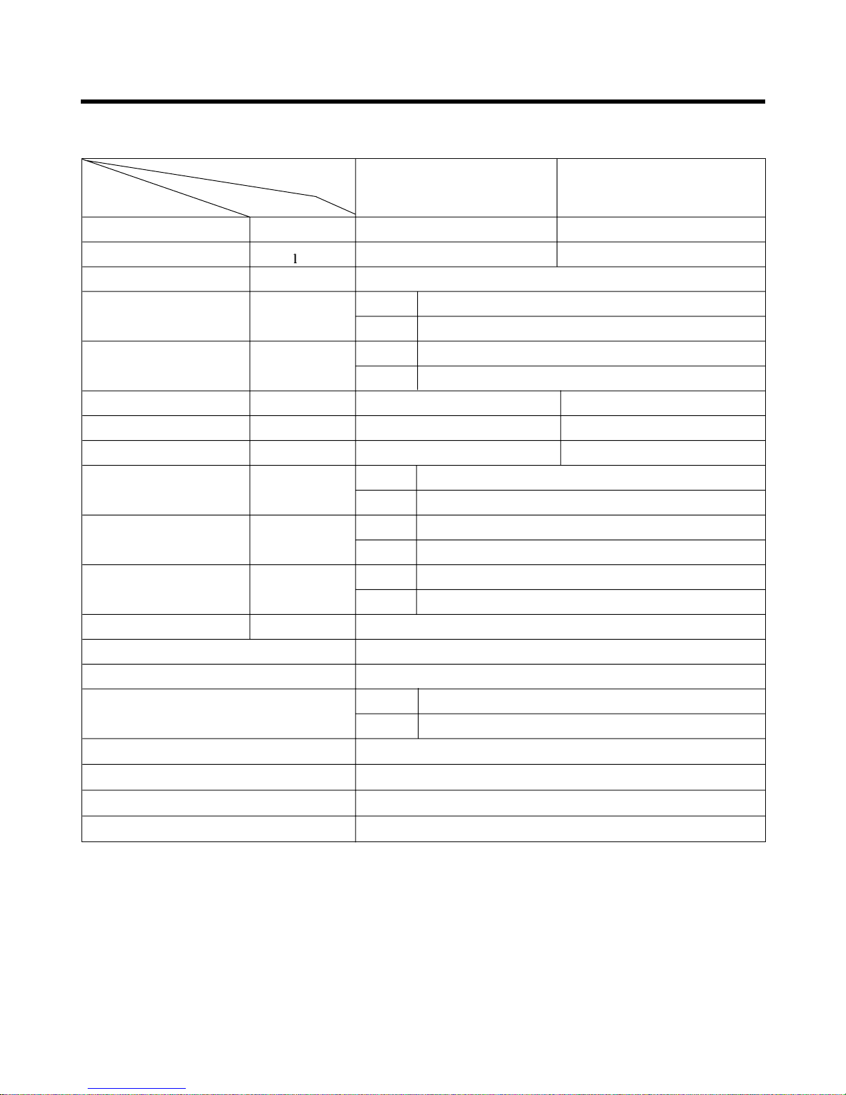
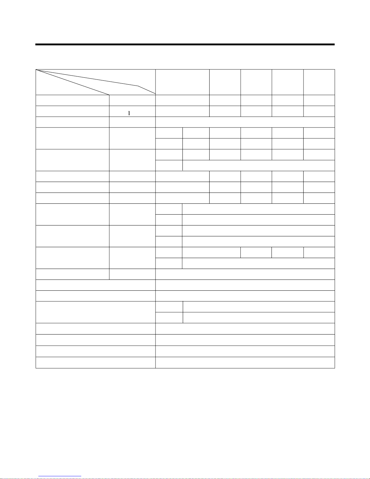
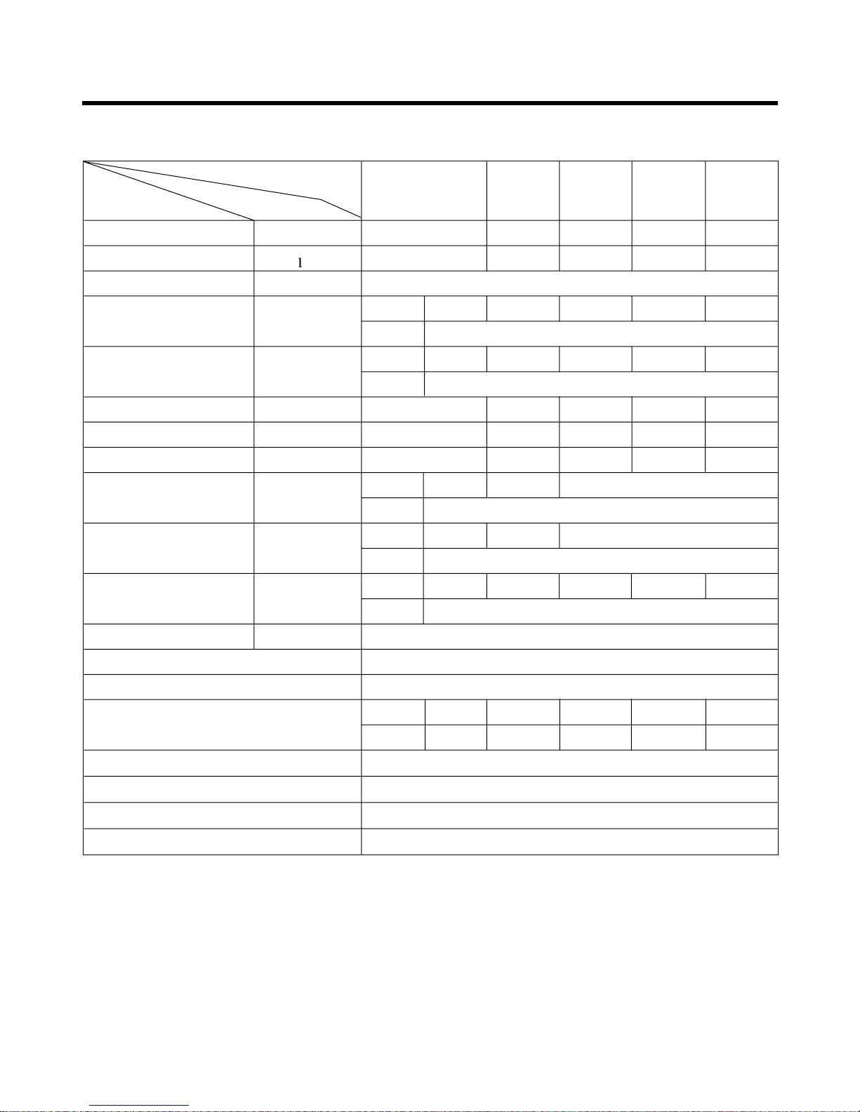
Product Specifications
17,000(4,270) 24,000(6,050)
1.6 1.6 x 2
1Ø, 220, 60HZ
9.0
49
38+1
56+1
2,260 2,410
10.5 11.5
7.5 9.96
14.4
90
888 x 287 x 170
870 x 655 x 320
9
61
1,650(at 7.5m)
O
L.C.D Wireless
1/4"(6.35)
1/2"(12.7)
O
O
0.75mm
2
2.5mm
2
Operation
A or B unit
A + B unit
Unit
Indoor
Outdoor
Indoor
Outdoor
Indoor
Outdoor
Indoor
Outdoor
Indoor
Outdoor
Liquid
Gas
Item
Cooling Capacity Btu/h(kcal/h)
Moisture Removal
/h
Power Source ø, V, Hz
Air Circulation m3/min
Noise Level(Low) dB(A)
Input W
Runnig Current A
E.E.R. Btu/h.w
Motor Output W
Dimensions(W x H x D)
mm
Net. Weight kg
Refrigerant(R-22) g
Airflow Direction Control(Up & Down)
Remocon Type
Service Valve
Drain Hose
Plasma Filter
Connecting Cable
Power Cord
1. LM-2422C2L, LM-2422A2L

- 6 -
17,800(4,486) 35,600(8,972)
2.0 2.0 x 2
1Ø, 220, 60HZ
13.1
58
40
57
1,900 3,650
8.7 16.8
9.4 9.8
21
90
1,080 x314 x 181
870 x 800 x 320
11
71
A: 820, B: 820 (at 7.5m)
O
L.C.D Wireless
1/4"(6.35)
5/8"(15.88)
O
LM-3622A2L only
1.5mm
2
3.5mm
2
Operation
A or B unit
A + B unit
Unit
Indoor
Outdoor
Indoor
Outdoor
Indoor
Outdoor
Indoor
Outdoor
Indoor
Outdoor
Liquid
Gas
Item
Cooling Capacity Btu/h(kcal/h)
Moisture Removal
/h
Power Source ø, V, Hz
Air Circulation m3/min
Noise Level(Low) dB(A)
Input W
Runnig Current A
E.E.R. Btu/h.w
Motor Output W
Dimensions(W x H x D)
mm
Net. Weight kg
Refrigerant(R-22) g
Airflow Direction Control(Up & Down)
Remocon Type
Service Valve
Drain Hose
Plasma Filter
Connecting Cable
Power Cord
2. LM-3620C2L, LM-3620A2L, LM-3622A2L
- 7 -
12,000(3,024)
13,000(3,276) 25,000(6,300) 23,800(5,998) 35,800(9,022)
1.4 1.5 2.9 2.5 3.9
1Ø, 220V, 60Hz
Indoor 9.0 9.5 9.0 + 9.5 9 + 9 9.0 x 3
Outdoor 58 - - - Indoor 37 38 - - Outdoor 57
1,300 2,100 3,200 2,400 3,600
5.7 9.3 13.6 10.1 14.8
9.2 6.2 7.8 9.9 9.9
Indoor 14.4 x 3
Outdoor 90
Indoor 888 x 287 x 170
Outdoor 870 x 800 x 320
Indoor 9 - - Outdoor 71
A: 550, B: 1,100 (at 7.5m)
O
L.C.D Wireless
Liquid 1/4"(6.35)
Gas 1/2"(12.7)
O
LM-3626A3L only
0.75mm
2
3.5mm
2
Operation
A-Unit
B or C-Unit
A+B or C B+C A+B+C
Unit
Item
Cooling Capacity Btu/h(kcal/h)
Moisture Removal /h
Power Source ø, V, Hz
Air Circulation m3/min
Noise Level(Low) dB(A)
Input W
Runnig Current A
E.E.R. Btu/h.w
Motor Output W
Dimensions(W x H x D)
mm
Net. Weight kg
Refrigerant(R-22) g
Airflow Direction Control(Up & Down)
Remocon Type
Service Valve
Drain Hose
Plasma Filter
Connecting Cable
Power Cord
3. LM-3625C3L/A3L, LM-3626A3L
- 8 -
24,000(6,048)
16,000(4,032)
40,000(10,080)
24,000(6,048)
48,000(12,096)
2.5 2.2 4.8 3.4 6.5
1Ø, 220V, 60Hz
Indoor 14.5 9.0 14.5 + 9.0 8.2 + 8.2
14.5 + 8.2 + 8.2
Outdoor 106
Indoor 47/44/40 42/40/38 - - Outdoor 60
2,500 2,300 4,500 2,500 4,700
11.0 10.5 20.0 11.0 21.0
9.6 7.0 8.9 9.6 10.6
Indoor 22 14.4
Outdoor 80 x 2
Indoor
1,180 x 314 x 181
888 x 287 x 170
Outdoor 1,225 x 900 370
Indoor 11 9 - - -
Outdoor 106
1,570 1,300 - - -
O
L.C.D Wireless
Liquid
3/8"(9.52) 1/4"(6.35)
---
Gas
5/8"(15.88) 1/2"(12.7)
---
O
LM-4822C3L/A3L only
0.75mm
2
5.5mm
2
Operation
A-Unit
B or C-Unit
A+B or C B+C A+B+C
Unit
Item
Cooling Capacity Btu/h(kcal/h)
Moisture Removal /h
Power Source ø, V, Hz
Air Circulation m3/min
Noise Level(Low) dB(A)
Input W
Runnig Current A
E.E.R. Btu/h.w
Motor Output W
Dimensions(W x H x D)
mm
Net. Weight kg
Refrigerant(R-22) g
Airflow Direction Control(Up & Down)
Remocon Type
Service Valve
Drain Hose
Plasma Filter
Connecting Cable
Power Cord
4. LM-4822C3L, LM-4822A3L
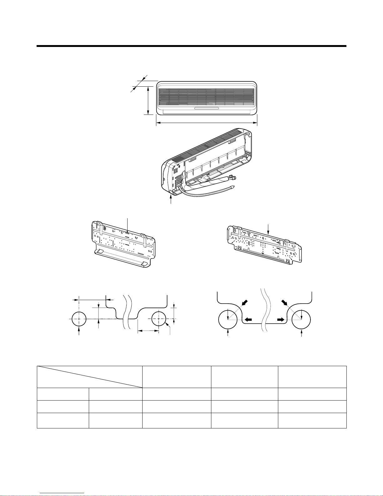
1. Indoor Unit
- 9 -
Dimensions
Installation plate
Installation plate
Right rear piping
Left rear piping
ø70mm
ø70mm
50mm
20mm
20mm
80mm
A
A
ø70mm
Center
Center
ø70mm
Left rear piping Right rear piping
A
A
D
H
W
Tubing hole cover
W mm 802 888 1,080
H mm 262 287 314
D mm 165 170 181
4.5K, 6K, 7K, 8K, 9K
Btu Series
9K, 10K, 12K Btu
Series
18K, 24K Btu
MODEL
DIM
( 4.5K, 6K, 7K, 8K, 9K )
( 4.5K, 6K, 7K, 8K, 9K )
( 9K, 10K, 12K, 18K, 24K )
( 9K, 10K, 12K, 18K, 24K )
- 10 -
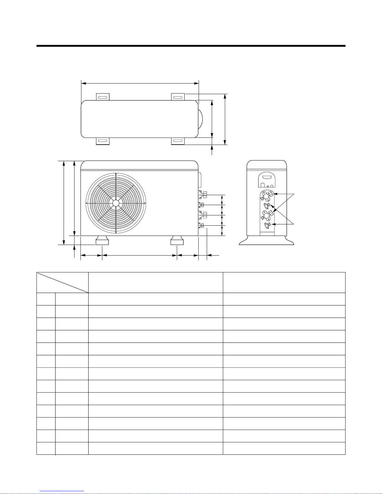
2. Outdoor Unit
2-1. LM-2422C2L, LM-2422A2L, LM-3622A2L, LM-3620C2L, LM-3620A2L
W
D
L1
L2
L9
L4
L3
H
L10
L10
L10
L8
Gas side
3-Way valve
Liquid side
2-Way valve
L7L5L6
W mm 870 870
H mm 655 800
D mm 320 320
L1 mm 370 370
L2 mm 25 25
L3 mm 630 775
L4 mm 25 25
L5 mm 546 546
L6 mm 160 160
L7 mm 160 160
L8 mm 64 64
L9 mm 76.5 76.5
L10 mm 50 50
LM-2422C2L, LM-2422A2L
LM-3620C2L, LM-3622A2L, LM-3620A2L
MODEL
DIM

- 11 -
2-2. LM-3625C3L/A3L, LM-3626A3L
W
L5L6 L7 L8
L3
H
D
L1
L2
L4
L10L9
Gas side
3-way valve
Liquid side
2-way valve
L10L10L10L10
W mm 870
H mm 800
D mm 320
L1 mm 370
L2 mm 25
L3 mm 775
L4 mm 25
L5 mm 546
L6 mm 160
L7 mm 160
L8 mm 64
L9 mm 76.5
L10 mm 50
LM-3625C3L/A3L, LM-3626A3L
MODEL
DIM
- 12 -
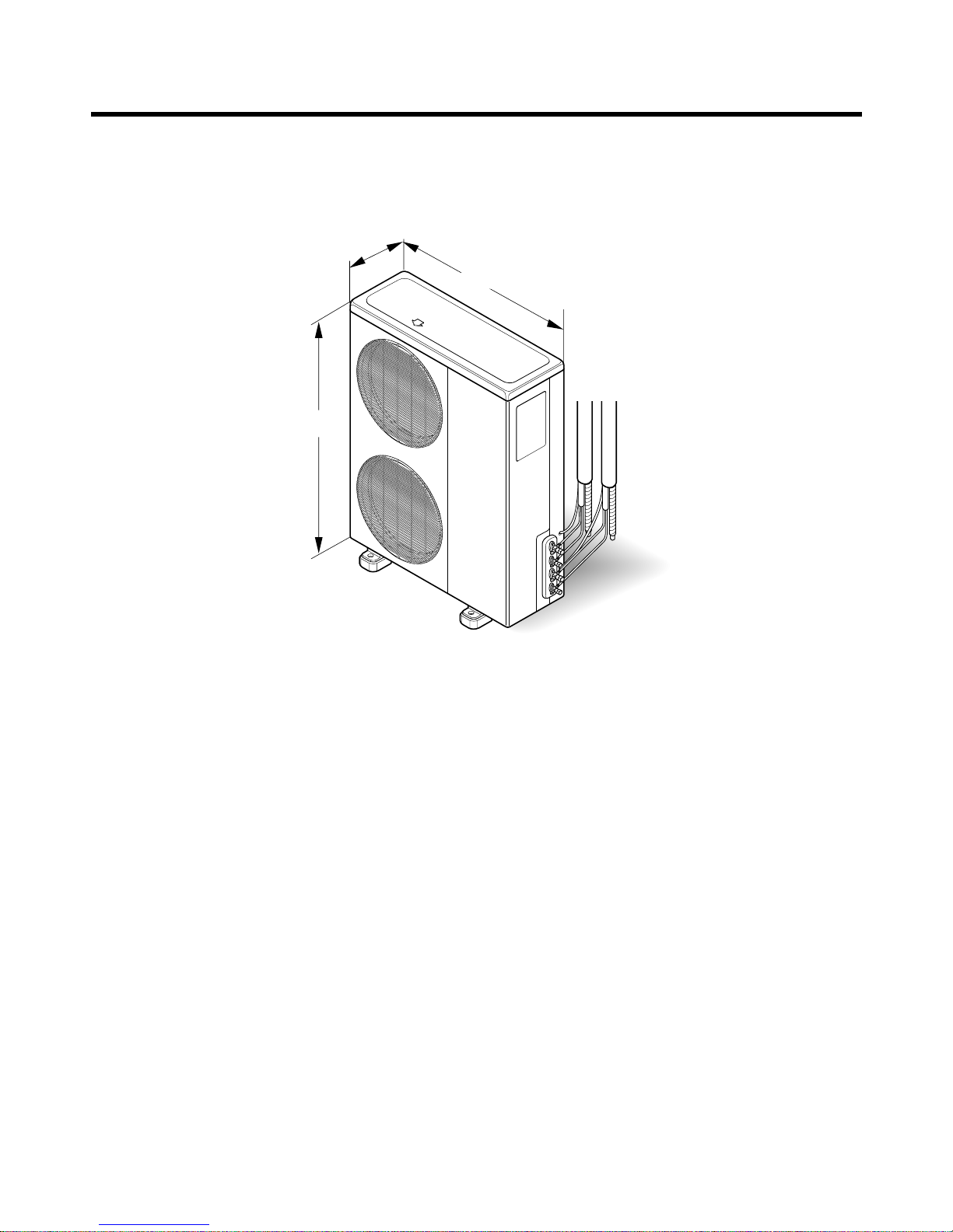
900
1,225
370
2-3. LM-4822C3L, LM-4822A3L
- 13 -
Refrigeration Cycle Diagram
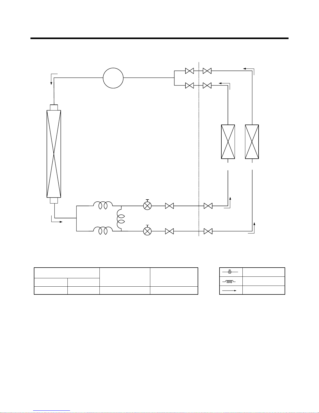
1. LM-2422C2L, LM-2422A2L
COMP
3-WAY
Valve
ø6.35
ø12.7
ø12.7
ø6.35
HEAT
EXCHANGER
HEAT
EXCHANGER
(A Unit) (B Unit)
Pipe Size (Diameter : inch)
Max.
piping length
(m)
Max.
piping elevation
(m)
Gas Liquid
1/2" 1/4" 10~15 5~7
ex)
Solenoid Valve
Capillary
Cooling
- 14 -
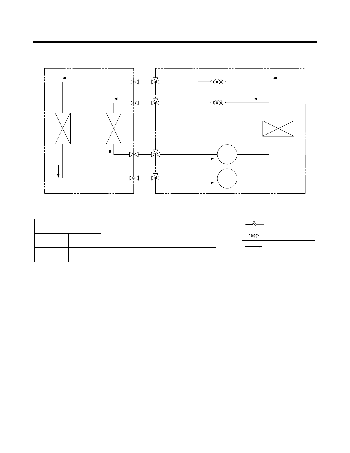
2. LM-3620C2L, LM-3622A2L, LM-3620A2L
Pipe Size (Diameter : inch)
Max.
piping length
(m)
Max.
piping elevation
(m)
Gas Liquid
5/8" 1/4" 20 10
ex)
Solenoid Valve
Capillary
Cooling & Deice
A-UNIT B-UNIT
CAPILLARY TUBE
LIQUID SIDE
2-WAY VALVE
GAS SIDE
3-WAY VALVE
HEAT
EXCHANGER
(EVAPORATOR)
HEAT
EXCHANGER
(CONDENSER)
COMPRESSOR
B
COMPRESSOR
A
- 15 -
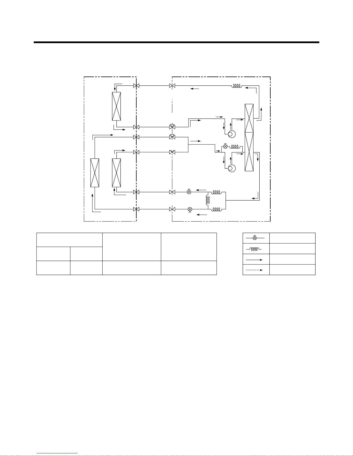
3. LM-3625C3L/A3L, LM-3626A3L
Pipe Size (Diameter : inch)
Max.
piping length
(m)
Max.
piping elevation
(m)
Gas Liquid
(1/2") 1/4" 10~15 5~7
ex)
Solenoid Valve
Capillary
Cooling & Deice
Heating
Indoor Unit Outdoor Unit
Heat
Exchanger
A-Unit
Heat
Exchanger
Comp-A
Comp-B
B-Unit
C-Unit
Heat
Exchanger
2- WAY
Valve
3- WAY
Valve
2- WAY
Valve
3- WAY
Valve
- 16 -
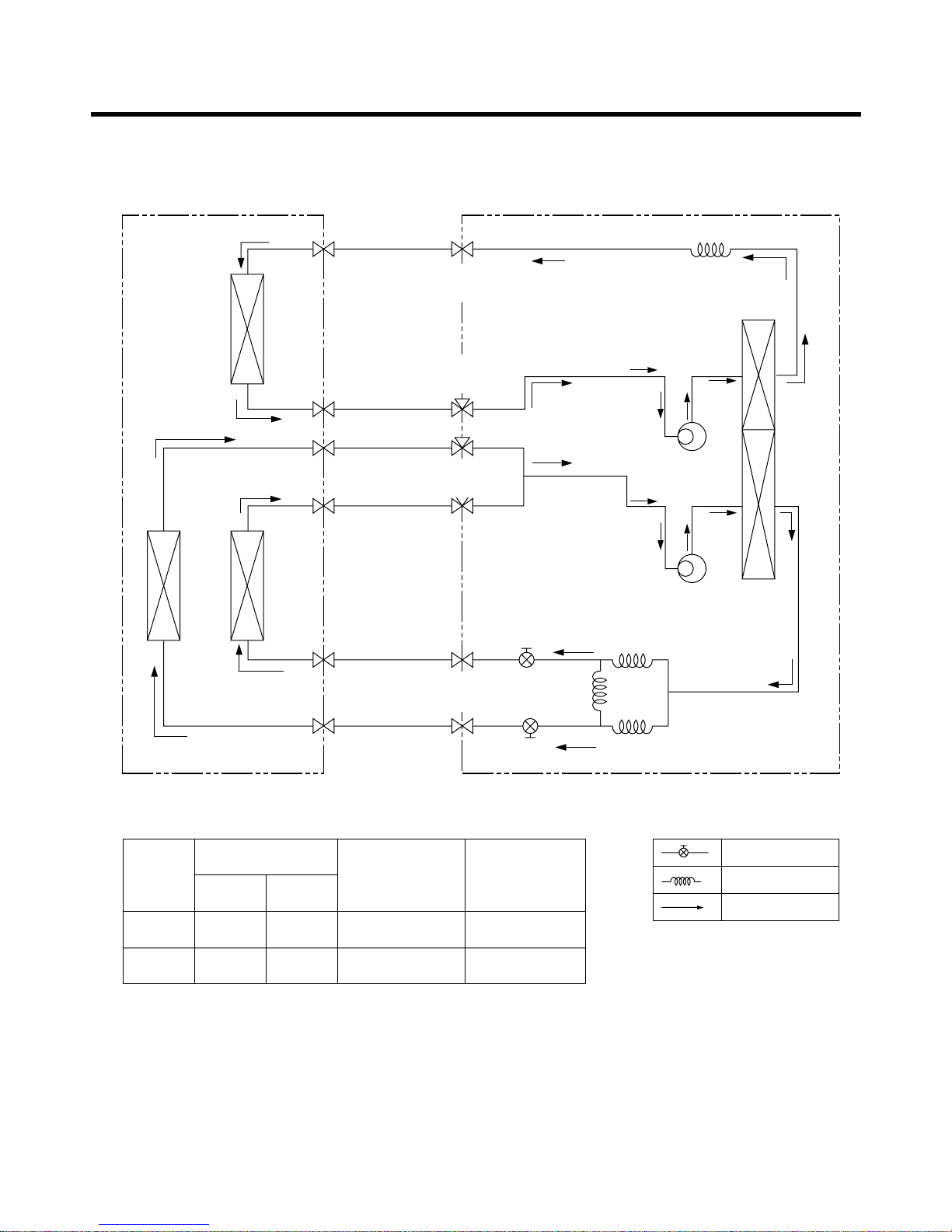
4. LM-4822C3L, LM-4822A3L
Pipe Size
(Diameter : inch)
Indoor
B/C
Max.
piping length
(m)
Max.
piping elevation
(m)
Gas Liquid
3/8"(1/2") 1/4" 15 7
A
5/8" 3/8" 30 15
ex)
Solenoid Valve
Capillary
Cooling
Indoor Unit Outdoor Unit
Heat
Exchanger
A-Unit
Heat
Exchanger
Comp-A
Comp-B
B-Unit
C-Unit
Heat
Exchanger
2- WAY
Valve
3- WAY
Valve
2- WAY
Valve
3- WAY
Valve
- 17 -
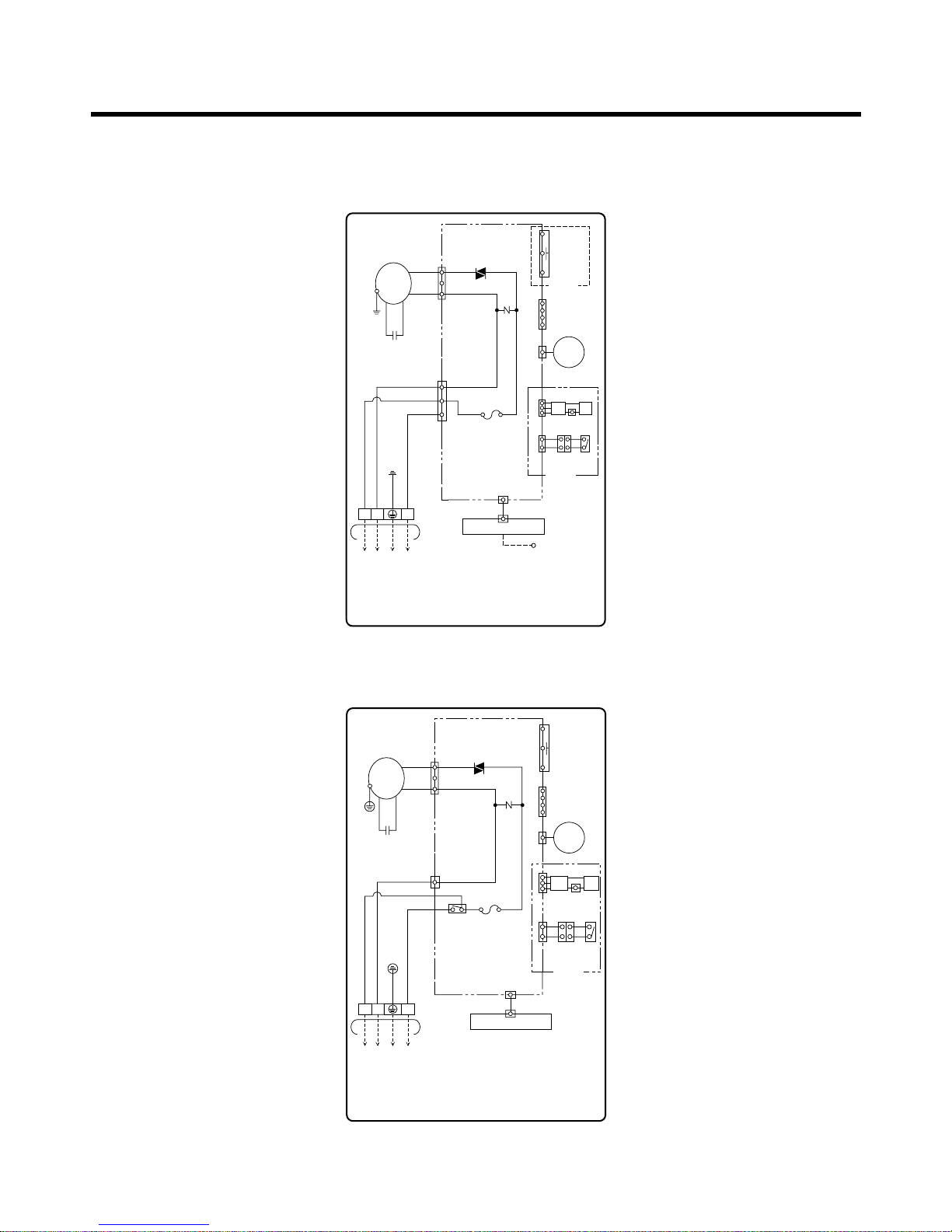
Wiring Diagram(Indoor Unit)
1. LM-2422C2L, LM-2422A2L, LM-3625C3L/A3L, LM-3626A3L,
LM-4822C3L, LM-4822A3L
2. LM-3620C2L, LM-3622A2L, LM-3620A2L
3854A20080W
INDOOR WIRING DIAGRAM
CN-DISP1
CN-U/D
FUSE
AC250V/T2A
CN-TH1
TRIAC
SH-CAPA.
BR
YL
OR
BK
CN-TAB1
ZNR
CN-MOTOR
THERMISTOR
FORCED
OPERATION
AUTO
RESTART
REMOTE
CONTROL
STEP
MOTOR
MOTOR
MAIN PCB
ASM
DISPLAY PCB ASM
TO OUTDOOR UNIT
PILLAR
TERMINAL
BR
BL
YL
GN/YL
1(L) 2(N
)
3
RY-COMP.
4
3
H.V.B A/CL
RD
BK BK
BK BK
BK BK
LIMIT
S/W
OPTION
3854A20023X
INDOOR WIRING DIAGRAM
CN-DISP1
CN-U/D
FUSE
AC250V/T2A
CN-TH
SSR
SH-CAPA.
BR
YL
OR
BK
CN-POWER CN-FAN
ZNR
THERMISTOR
FORCED
OPERATION
AUTO
RESTART
REMOTE
CONTROL
STEP
MOTOR
MOTOR
MAIN PCB
ASM
DISPLAY PCB ASM
TO OUTDOOR UNIT
PILLAR
TERMINAL
BR
BL
YL
GN/YL
1(L) 2(N
)
3
OPTION
ON/OFF S/W(OPTION)
RD
BK BK
LIMIT
S/W
H.V.B A/CL
OPTION
BK BK
BK BK
- 18 -
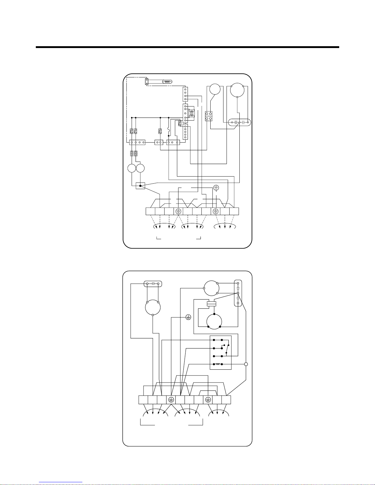
Wiring Diagram(Outdoor Unit)
3. LM-2422C2L, LM-2422A2L
4. LM-3620C2L, LM-3622A2L, LM-3620A2L
RD
R
C
BR
BK
A-UNIT
TO INDOOR UNIT
OUTDOOR WIRING DIAGRAM 3854A20023Y
B-UNIT MAIN POWER
BL
OR
OR
RD
RD
BK
BK
WH
MOTOR
T/B
C
R
FCH
S
BL
WH
YL
BR
COMP
"B"
CAPACITOR
12
34
56
78
WH
WH
BK
WH
WH
WH
TERMINAL
BLOCK
POWER
RELAY
GN/YL
GN/YL
S
COMP
"A"
YL
CAPACITOR
1(L
)
1(L
)
1(L
)
2(N
)
2(N
)
2(N
)
33
CN-TH
CCS
R
F
TERMINAL
BLOCK(
10P
)
1(L
)
2(N
)
2(N
)
1(L
)
31(L)2(N
)
3
A-UNIT
T/BLOCK
BL BL
BK
BK
TRANS FORMER
OR
THERMISTOR
YL
OR BK BR
WH
CAPA.
BK
MOTOR
COMP
BK
WH
BLYL
BK
B-UNIT
TO INDOOR UNIT
OUTDOOR WIRING DIAGRAM
3854A30076L
MAIN
POWER
A
CH
R
S
B
A
5
7
CN-COM
CN-TRANSCN-COMP
CN-POWER
RY-COMP
CN-S.V
S/VBS/V
CN-FAN
RY-S.V1
RY-S.V2
432 11321
5
RY-HI
FUSE(250V/3.15A)
MAIN P.C.B ASM
BK BK
WH
WH
WH
BL
BR
GN/YL
GN/YL
- 19 -
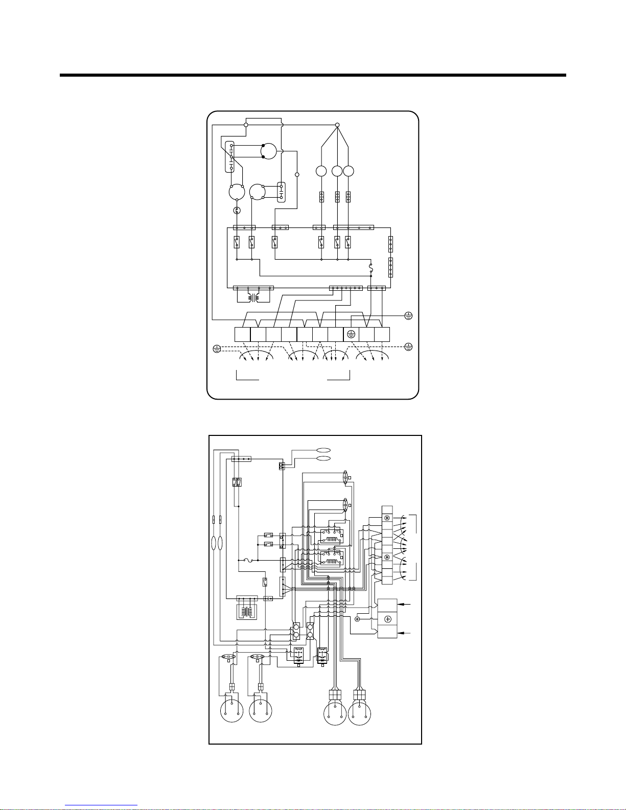
5. LM-3625C3L/A3L, LM-3626A3L
6. LM-4822C3L, LM-4822A3L
OUTDOOR WIRING
DIAGRAM
MAIN PCB
ASSY
B - THERMISTOR
C - UNITB - UNIT
TO INDOOR UNIT
POWER INPUT
1Ø, 220V, 60Hz
3(N) 4(L)
1(L) 1(L)2(N) 2(N)33 3
A - UNIT
A - THERMISTOR
BK
BK
BK
BK
BK
BK
LOW
HI
BK
BK
BK
BK
YL
OR
OR
OR
BK
BK
A - MOTOR
B - MOTOR
A - COMP
RY - COMP(B)
RY - COMP(A)
FUSE 250V / 3.15A
3854A30042Z
B - COMP
YL
OR
OR OR
BK
BK
BK
BK
RD
S
CR
S
CR
S
CR
S
CR
BR YLWHBL
BK
BR
BR
BR
BR
BR
WH
WH
WH
WH
WH
TB1 TB3
TB4
TB2
WH
WH
WH
WH
BL
BL
BL BL
BLBL
BL
BL
BL
YL
RD
YL
RD
RD WH
B S / V C S / V
YL
86142
86142
RD
GN / YL
GN / YL
GN / YL
CN - FAN
CN - COM
RY - HI
CN - POWER
CN - COMP
CN - TH1
753
BA
CN - TRANS
CN - SV
RD
C S / V B S / V
RY - SV1
RY - SV2
B
A
12
34
56
78
12
34
56
78
0
0
A
B
B
A
A
B
A
B
BK
T/B1BK
CAPA.
CAPA.
OLP
RY1
RY2
RY3
RY8
RY7
RY9
CN-TH2
CN-SV
CN-TH1
FCH
1
BK
BK
BK
T/B2
WHBR
BR
BL
RD WH
GN/YL
TERMINAL
BLOCK
WH
BK
WH
BK
BK
BK
RD
BK
BK
BR
YL
YL
OR
RD
SSR
R
C
C
BK
BL RD
CN-FAN
CN-BYPASS
CN-COMP
BK
"A"
COMP
"B"
COMP
MOTOR
FUSE T3.15A
CN-POWERCN-COM
MAIN PCB ASSY
CN-TRANS
TRANS-
FORMER
A-UNIT B-UNIT
TO INDOOR UNIT
C-UNIT MAIN
POWER
OUTDOOR WIRING DIAGRAM
3854A20023Z
T/B3
BYPASS
B ROOM
C ROOM
S.V
S.V
S.V
1(L) 1(L) 1(L)
2(N) 2(N) 2(N)
33 3

- 20 -
Operation Details
1. MAIN UNIT FUNCTION
• DISPLAY
1) C/O Model
Operation Indicator
• On while in appliance operation, off while in appliance pause
• Flashing while in disconnection or short in Thermistor (3 sec off / 0.5 sec on)
Sleep Timer Indicator
• On while in sleep timer mode, off when sleep timer cancel or appliance operation pause
Timer Indicator
• On while in timer mode (on/off), off when timer mode is completed or canceled.
Comp. Running Incidator
• While in appliance operation, on while in outdoor unit compressor running, off while in compressor off
2) H/P Model
Operation Indicator
• On while in appliance operation, off while in appliance pause
• Flashing while in disconnection or short in Thermistor (3 sec off / 0.5 sec on)
Sleep Timer Indicator
• On while in sleep timer mode, off when sleep timer cancel or appliance operation pause
Timer Indicator
• On while in timer mode (on/off), off when timer mode is completed or canceled
Defrost Indicator
• Off except when hot start during heating mode operation or while in defrost control
■ Cooling Mode Operation
• When the intake air temperature reaches 0.5°C below the setting temp, the compressor and the outdoor fan
stop.
• When it reaches 0.5°C above the setting temp, they start to operate again.
Compressor ON Temp ➲ Setting Temp+0.5°C
Compressor OFF Temp ➲ Setting Temp-0.5°C
• While in compressor running, operating with the airflow speed set by the remote control. While in compressor not running, operating with the low airflow speed regardless of the setting.
■ Healthy Dehumidification Mode
• When the dehumidification operation input by the remote control is received, the intake air temperature is
detected and the setting temp is automatically set according to the intake air temperature.
26°C ≤ Intake Air Temp ➲ 25°C
24°C ≤ Intake Intake Air Temp<26°C ➲ Intake Air Temp-1°C
18°C ≤ Intake Intake Air Temp<24°C ➲ Intake Air Temp-0.5°C
Intake Air Temp<18°C ➲ 18°C

- 21 -
• While in compressor off, the indoor fan repeats low airflow speed and pause.
• While the intake air temp is between compressor on temp. and compressor off temp., 10-min dehumidifica-
tion operation and 4-min compressor off repeat.
Compressor ON Temp. ➲ Setting Temp+0.5°C
Compressor OFF Temp. ➲ Setting Temp-0.5°C
• In 10-min dehumidification operation, the indoor fan operates with the low airflow speed.
■ Heating Mode Operation(H/P model)
• When the intake air temp reaches +3°…above the setting temp, the compressor is turned off. When below
the setting temp, the compressor is turned on.
Compressor ON Temp. ➲ Setting Temp.
Compressor OFF Temp. ➲ Setting Temp.+3°C
• While in compressor on, the indoor fan is off when the indoor pipe temp. is below 20°C, when above 28°C ,
it operates with the low or setting airflow speed. When the indoor pipe temp is between 20°C and 28°C, it
operates with Super-Low(while in sleep mode, with the medium airflow speed).
• While in compressor off, the indoor fan is off when the indoor pipe temp is below 33°C, when above 35°C ,
it operates with the low airflow speed.
• If overloaded while in heating mode operation, in order to prevent the compressor from OLP operation, the
outdoor fan is turned on/off according to the indoor pipe temp.
• While in defrost control, both of the indoor and outdoor fans are turned off.
■ Defrost Control(H/P model)
• Defrost operation is controlled by timer and sensing temperature of outdoor pipe.
• The first defrost starts only when the outdoor pipe temperature falls below -6°C after 60 minutes passed
from starting of heating operation and more than 10 minutes operation of compressor.
• Defrost ends after 12 minutes passed from starting of defrost operation or after the outdoor fan operates
within max. 2 minutes 30 seconds when the outdoor pipe temperature rises over 12°C even it before 12
minutes.
• The second defrost starts only when the outdoor pipe temperature falls below -6°C after 60 minutes passed
from ending of the first defrost and more than 10 minutes operation of compressor.
■ Cooling overload
• Control indoor fan by sensing outdoor pipe temperature.
• One step down from setting fan speed if pipe temperature is oven 50°C and if below 45°C, operate on set-
ting temperature.
• One of the outdoor fan is OFF if pipe temperature is below 0°C and outdoor fan is ON if pipe temperature is
over 0°C.
■ Heating overload(H/P models)
• Outdoor fan ON/OFF by sensing outdoor pipe temperature.
• Outdoor fan is OFF if pipe temperature is over 6.5°C and outdoor fan is ON if pipe temperature is below
0°C.
• Outdoor fan is off if any one part is heating overload condition.

- 22 -
■ Fuzzy Operation (C/O Model)
• According to the temperature set by Fuzzy rule, when the intake air temp is 0.5°C or more below the setting
temp, the compressor is turned off. When 0.5°C or more above the setting temp, the compressor is turned on.
Compressor ON Temp ➲ Setting Temp + 0.5°C
Compressor OFF Temp ➲ Setting Temp + 0.5°C
• At the beginning of Fuzzy mode operation, the setting temperature is automatically selected according to the
intake air temp at that time.
26°C ≤ Intake Air Temp ➲ 25°C
24°C ≤ Intake Air Temp < 26°C ➲ Intake Air Temp + 1°C
22°C ≤ Intake Air Temp < 24°C ➲ Intake Air Temp + 0.5°C
18°C ≤ Intake Air Temp < 22°C ➲ Intake Air Temp
Intake Air Temp<18°C ➲ 18°C
• When the Fuzzy key (Temperature Control key) is input after the initial setting temperature is selected, the
Fuzzy key value and the intake air temperature at that time are compared to select the setting temperature
automatically according to the Fuzzy rule.
• While in Fuzzy operation, the airflow speed of the indoor fan is automatically selected according to the
temperature.
■ Fuzzy Operation (H/P Model)
• When any of operation mode is not selected like the moment of the power on or when 3 hrs has passed since
the operation off, the operation mode is selected.
• When determining the operation mode, the compressor, the outdoor fan, and the 4 way valve are off and only
the indoor fan is operated for 15 seconds. Then an operation mode is selected according to the intake air
temp at that moment as follows.
24°C ≤ Inatake Air Temp ➲ Fuzzy Operation for Cooling
21°C ≤ Inatake Air Temp<24°C ➲ Fuzzy Operation for Dehumidification
Inatake Air Temp<21°C ➲ Fuzzy Operation for Heating
• If any of the operation modes among cooling / dehumidification / heating mode operations is carried out for 10
sec or longer before Fuzzy operation, the mode before Fuzzy operation is operated.
1) Fuzzy Operation for Cooling
• According to the setting temperature selected by Fuzzy rule, when the intake air temp is 0.5°C or more below
the setting temp, the compressor is turned off. When 0.5°C or more above the setting temp, the compressor
is turned on.
Compressor ON Temp ➲ Setting Temp +0.5°C
Compressor OFF Temp ➲ Setting Temp + 0.5°C
• At the beginning of Fuzzy mode operation, the setting temperature is automatically selected according to the
intake air temp at that time.
26°C≤ Intake Air Temp ➲ 25°C
24°C≤ Intake Air Temp<26°C ➲ Intake Air Temp + 1°C
22°C≤ Intake Air Temp<24°C ➲ Intake Air Temp + 0.5°C
18°C≤ Intake Air Temp<22°C ➲ Intake Air Temp
Intake Air Temp<18°C ➲ 18°C
• When the Fuzzy key (Temperature Control key) is input after the initial setting temperature is selected, the
Fuzzy key value and the intake air temperature at that time are compared to select the setting temperature
automatically according to the Fuzzy rule.
• While in Fuzzy operation, the airflow speed of the indoor fan is automatically selected according to the temperature.

- 23 -
2) Fuzzy Operation for Dehumidification
• According to the setting temperature selected by Fuzzy rule, when the intake air temp is 0.5°C or more
below the setting temp, the compressor is turned off. When 0.5°C or more above the setting temp, the
compressor is turned on.
Compressor ON Temp ➲ Setting Temp + 0.5°C
Compressor OFF Temp ➲ Setting Temp+0.5°C
• At the beginning of Fuzzy mode operation, the setting temperature is automatically selected according to
the intake air temp at that time.
26°C ≤ Intake Air Temp ➲ 25°C
24°C ≤ Intake Air Temp<26°C ➲ Intake Air Temp+1°C
22°C ≤ Intake Air Temp<24°C ➲ Intake Air Temp+0.5°C
18°C ≤ Intake Air Temp<22°C ➲ Intake Air Temp
Intake Air Temp<18°C ➲ 18°C
• When the Fuzzy key (Temperature Control key) is input after the initial setting temperature is selected, the
Fuzzy key value and the intake air temperature at that time are compared to select the setting temperature
automatically according to the Fuzzy rule.
• While in Fuzzy operation, the airflow speed of the indoor fan repeats the low airflow speed or pause as in
dehumidification operation.
3) Fuzzy Operation for Heating
• According to the setting temperature selected by Fuzzy rule, when the intake air temp is 3°C or more above
the setting temp, the compressor is turned off. When below the setting temp, the compressor is turned on.
Compressor ON Temp ➲ Setting Temp
Compressor OFF Temp ➲ Setting Temp + 3°C
• At the beginning of Fuzzy mode operation, the setting temperature is automatically selected according to
the intake air temp at that time.
20°C≤Intake Air Temp ➲ Intake Air Temp + 0.5°C
Intake Air Temp<20°C ➲ 20°C
• When the Fuzzy key (Temperature Control key) is input after the initial setting temperature is selected, the
Fuzzy key value and the intake air temperature at that time are compared to select the setting temperature
automatically according to the Fuzzy rule.
• While in Fuzzy operation, the airflow speed of the indoor fan is set to the high or the medium according to
the intake air temperature and the setting temperature.
■ Airflow Speed Selection
• The airflow speed of the indoor fan is set to high, medium, low, or chaos (auto) by the input of the airflow
speed selection key on the remote control.
■ On-Timer Operation
• When the set time is reached after the time is input by the remote control, the appliance starts to operate.
• The timer LED is on when the on-timer is input. It is off when the time set by the timer is reached.
• If the appliance is operating at the time set by the timer, the operation continues.

- 24 -
■ Off-Timer Operation
• When the set time is reached after the time is input by the remote control, the appliance stops operating.
• The timer LED is on when the off-timer is input. It is off when the time set by the timer is reached.
• If the appliance is on pause at the time set by the timer, the pause continues.
■ Off-Timer <=> On-Timer Operation
• When the set time is reached after the on/off time is input by the remote control, the on/off-timer operation
is carried out according to the set time.
■ Sleep Timer Operation
• When the sleep time is reached after <1,2,3,4,5,6,7,0(cancel) hr> is input by the remote control while in
appliance operation, the operation of the appliance stops.
• While the appliance is on pause, the sleep timer mode cannot be input.
• While in cooling mode operation, 30 min later since the start of the sleep timer, the setting temperature
increases by 1°C. After another 30 min elapse, it increases by 1°C again.
• When the sleep timer mode is input while in cooling cycle mode, the airflow speed of the indoor fan is set to
the low.
• When the sleep timer mode is input while in heating cycle mode, the airflow speed of the indoor fan is set to
the medium.
■ Chaos Swing Mode
• By the Chaos Swing key input, the upper/lower vane automatically operates with the Chaos Swing or they
are fixed to the desired direction.
• While in Chaos Swing mode, the angles of cooling and heating cycle operations are different.
■ Chaos Natural Wind Mode
• When the Chaos Natural Wind mode is selected and then operated, the high, medium, or low speed of the
airflow mode is operated for 2~15 sec. randomly by the Chaos Simulation.
■ Jet Cool Mode Operation (C/O Model)
• If the Jet Cool key is input at any operation mode while in appliance operation, the Jet Cool mode operates.
• In the Jet Cool mode, the indoor fan is operated at super-high speed for 30 min at cooling mode operation.
• In the Jet Cool mode operation, the room temperature is controlled to the setting temperature, 18°C
• When the sleep timer mode is input while in the Jet Cool mode operation, the Jet Cool mode has the priori-
ty.
• When the Jet Cool key is input, the upper/lower vanes are reset to those of the initial cooling mode and
then operated in order that the air outflow could reach further.
■ Jet Cool Mode Operation (H/P Model)
• While in heating mode or Fuzzy operation, the Jet Cool key cannot be input. When it is input while in the
other mode operation (cooling, dehumidification, ventilation), the Jet Cool mode is operated.
• In the Jet Cool mode, the indoor fan is operated at super-high speed for 30 min at cooling mode operation.
• In the Jet Cool mode operation, the room temperature is controlled to the setting temperature, 18°C.
• When the sleep timer mode is input while in the Jet Cool mode operation, the Jet Cool mode has the priori-
ty.
• When the Jet Cool key is input, the upper/lower vanes are reset to those of the initial cooling mode and
then operated in order that the air outflow could reach further.
- 25 -
■ Auto Restarting Operation
• When the power is restored after a sudden power failure while in appliance operation, the mode before the
power failure is kept on the memory and the appliance automatically operates in the mode on the memory.
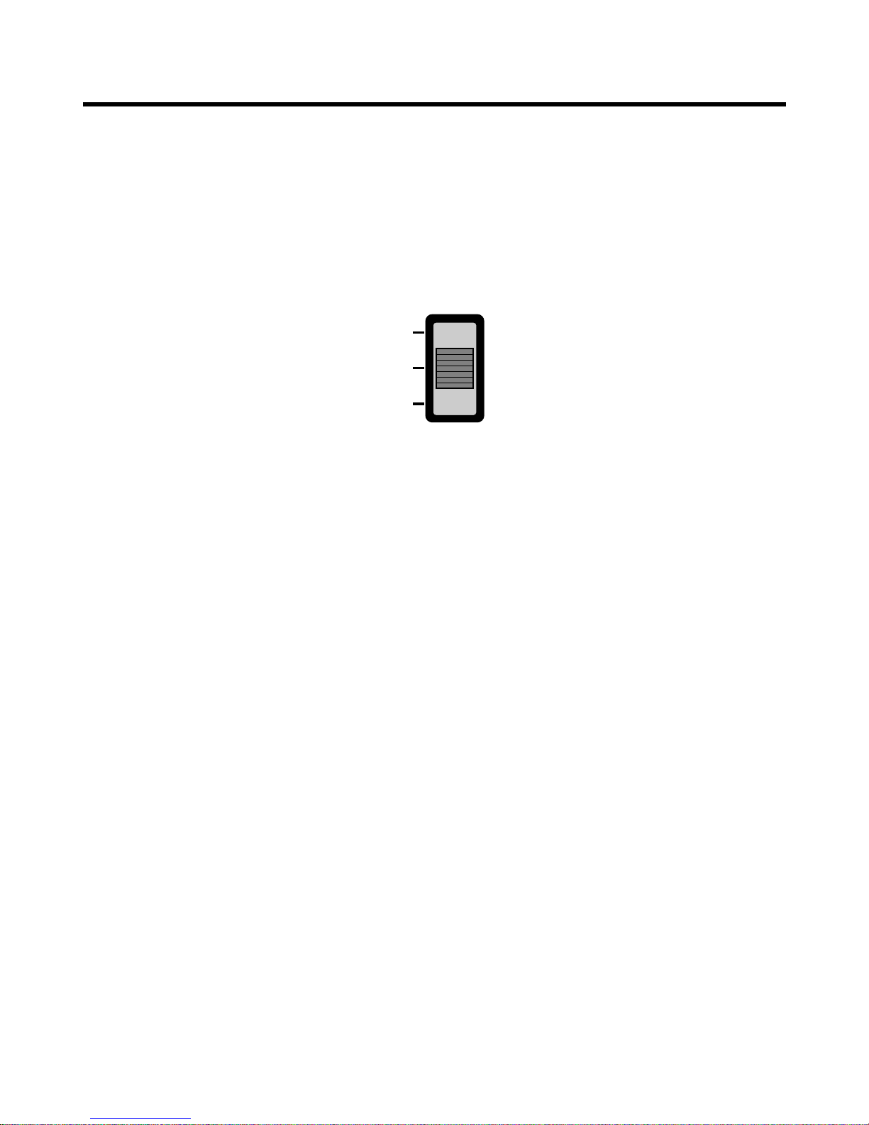
• The slide switch on the main unit of the appliance should be on the Auto Restarting position in order that
the Auto Restarting operation is available.
• Operation Mode that is kept on the memory
- State of Operation ON/OFF
- Operation Mode/Setting Temp/Selected Airflow Speed
- Sleep Timer Mode/Remaining Time of Sleep Timer (unit of hour)
Slide Switch
FORCED
OPERATION
AUTO
RESTART
REMOTE
CONTROL
■ Forced Operation (C/O Model)
• To operate the appliance by force in case that the remote control is lost, the forced operation selection
switch is on the main unit of the appliance to operate the appliance in the standard conditions.
• When the power is supplied while the slide switch is on the forced operation position, or when the slide
switch position is switched to the Auto Restarting position (or test operation) or switched from the remote
control position to the forced operation position while the power is on, the forced operation is carried out.
• When the slide switch position is switched from the forced operation position to the Auto Restarting position
or the remote control position, the forced operation is canceled and the appliance stops operating.
• The forced operation is carried out in cooling mode with the setting temperature 22°C and the high speed of
airflow.
■ Forced Operation (H/P Model)
• To operate the appliance by force in case that the remote control is lost, the forced operation selection
switch is on the main unit of the appliance to operate the appliance in the standard conditions.
• When the power is supplied while the slide switch is on the forced operation position, or when the slide
switch position is switched to the Auto Restarting (or test operation) position or switched from the remote
control position to the forced operation position while the power is on, the forced operation is carried out.
• When the slide switch position is switched from the forced operation position to the Auto Restarting position
or the remote control position, the forced operation is canceled and the appliance stops operating.
•
The forced operation is carried out in cooling mode with the setting temperature 22°C and the high speed of airflow.
• In the forced operation mode, the indoor fan is operated at low speed for around 15 sec and then the operation condition is set according to the intake air temperature as follows.
24°C≤Intake Air Temp ➲ Cooling Mode Operation, 22°C, High Speed
21°C≤Intake Air Temp<24°C ➲ Dehumidification Operation, 23°C, High Speed
Intake Air Temp<21°C ➲ Heating Mode Operation, 24°C, High Speed
 Loading...