

LG LM-2421C2L/A2L, LM-3022C3L/A3L Service Manual

Multi Type Room Air Conditioner
SERVICE MANUAL
MODEL: LM-2421C2L/A2L
LM-3022C3L/A3L

Functions...................................................................................................................................... 3
Product Specifications................................................................................................................ 4
Dimensions...............................................................................................................................
.....
6
Refrigeration Cycle Diagram....................................................................................................... 9
Wiring Diagram........................................................................................................................... 11
Operation Details ........................................................................................................................12
Display Function/Self-diagnosis Function .............................................................................. 14
Installation.................................................................................................................................. 15
Operation.................................................................................................................................... 31
Disassembly of the parts (Indoor Unit).................................................................................... 32
2-way, 3-way Valve..................................................................................................................... 34
Cycle Troubleshooting Guide....................................................................................................38
Electronic Parts Troubleshooting Guide................................................................................. 40
Electronic Control Device ......................................................................................................... 46
Schematic Diagram.................................................................................................................... 47
Exploded View and Replacement Parts List............................................................................ 50
-2-
Contents
-3-
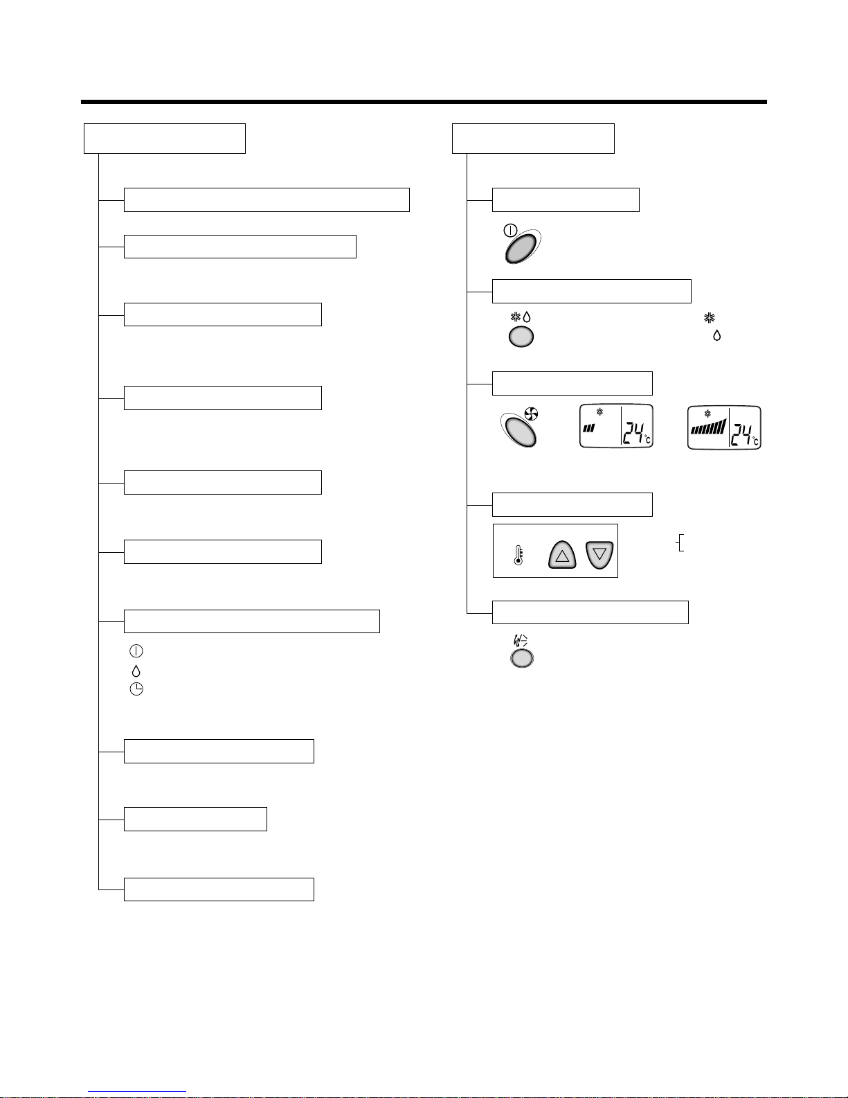
Functions
OUT
DOOR
Indoor Unit Remote Controller
Operation ON/OFF by Remote controller
Sensing the Room Temperature
• Room temperature sensor (THERMISTOR)
• Maintains the room temperature in
accordance with the Setting Temp.
• Indoor fan is delayed for 5 seconds at the
starting.
• Restarting is inhibited for approx. 3 minutes.
• High, Low
--- Lights up in operation
--- Lights up in Soft Dry Mode
--- Lights up in Timer Mode
--- Lights up in compressor operation
Room temperature control
Starting Current Control
Time Delay Safety Control
Indoor Fan Speed Control
• Intermittent operation of fan at low speed
Soft Dry Operation Mode
• Used to set the time of stopping operation.
Off Timer Control
Operation ON/OFF
Operation Mode Selection
Fan Speed Selection
Temperature Setting
Airflow Direction Control
• The louver can be set at the desired position
or swing up and down automatically.
Cooling Operation Mode ( )
Soft Dry Operation Mode ( )
(LOW)
Cooling
Down to 18°C
Up to 30°C,
(HIGH)
Airflow Direction Control
Operation indication Lamps (LED)
TEMPERATURE
LOWHIGH
TIME
OFF
hr.
TEMP.
TIME
OFF
hr.
TEMP.
-4-
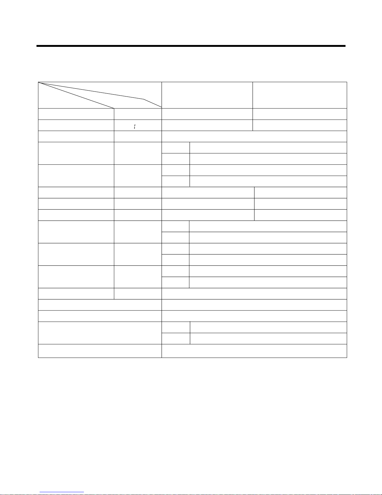
Product Specifications(Cooling Only)
17,000(4,270) 24,000(6,050)
1.6 1.6 x 2
1Ø, 220, 60HZ
9.0
49
38+1
56+1
2,260 2,410
10.5 11.5
7.5 9.96
14.4
90
888x287x170
870x655x320
9
61
1,650(7.5m Base)
O
L.C.D Wireless
1/4"(6.35)
1/2"(12.7)
O
Operation
A or B unit
A+Bunit
Unit
Indoor
Outdoor
Indoor
Outdoor
Indoor
Outdoor
Indoor
Outdoor
Indoor
Outdoor
Liquid
Gas
Item
Cooling Capacity Btu/h(kcal/h)
Moisture Removal /h
Power Source ø, V, Hz
Air Circulation m3/min
Noise Level(Low) dB(A)
Input W
Runnig Current A
E.E.R. Btu/h.w
Motor Output W
Dimensions(W x H x D)
mm
Net. Weight kg
Refrigerant(R-22) g
Airflow Direction Control(Up & Down)
Remocon Type
Service Valve
Drain Hose
1. LM-2421C2L/A2L

-5-
14,000(4,000)
14,000(4,000) 22,000(6,000) 22,000(5,800) 20,000(7,300)
1.4 1.6 3 3.2 4.6
1Ø, 220V, 60Hz
Indoor 9.5 9.5 8.8 + 7.8 7.8 + 7.8
8.8+7.8+7.8
Outdoor 53 - - - Indoor 38 40 - - Outdoor 60
2,250 2,250 2,500 2,500 2,600
10.5 10.5 11.5 11.5 12
6.22 6.22 8.8 8.8 10.77
Indoor 13.6/15
Outdoor 90
Indoor 888 x 287 x 170
Outdoor 870 x 655 x 320
Indoor 10 - - Outdoor 63
1,800
O
L.C.D Wireless
Liquid 1/4"(6.35) - - Gas 1/2"(12.7) - - -
O
Operation
A-Unit
BorC-Unit
A+B or C B+C A+B+C
Unit
Item
Cooling Capacity Btu/h(kcal/h)
Moisture Removal /h
Power Source ø, V, Hz
Air Circulation m3/min
Noise Level(Low) dB(A)
Input W
Runnig Current A
E.E.R. Btu/h.w
Motor Output W
Dimensions(W x H x D)
mm
Net. Weight kg
Refrigerant(R-22) g
Airflow Direction Control(Up & Down)
Remocon Type
Service Valve
Drain Hose
2. LM-3022C3L/A3L
-6-
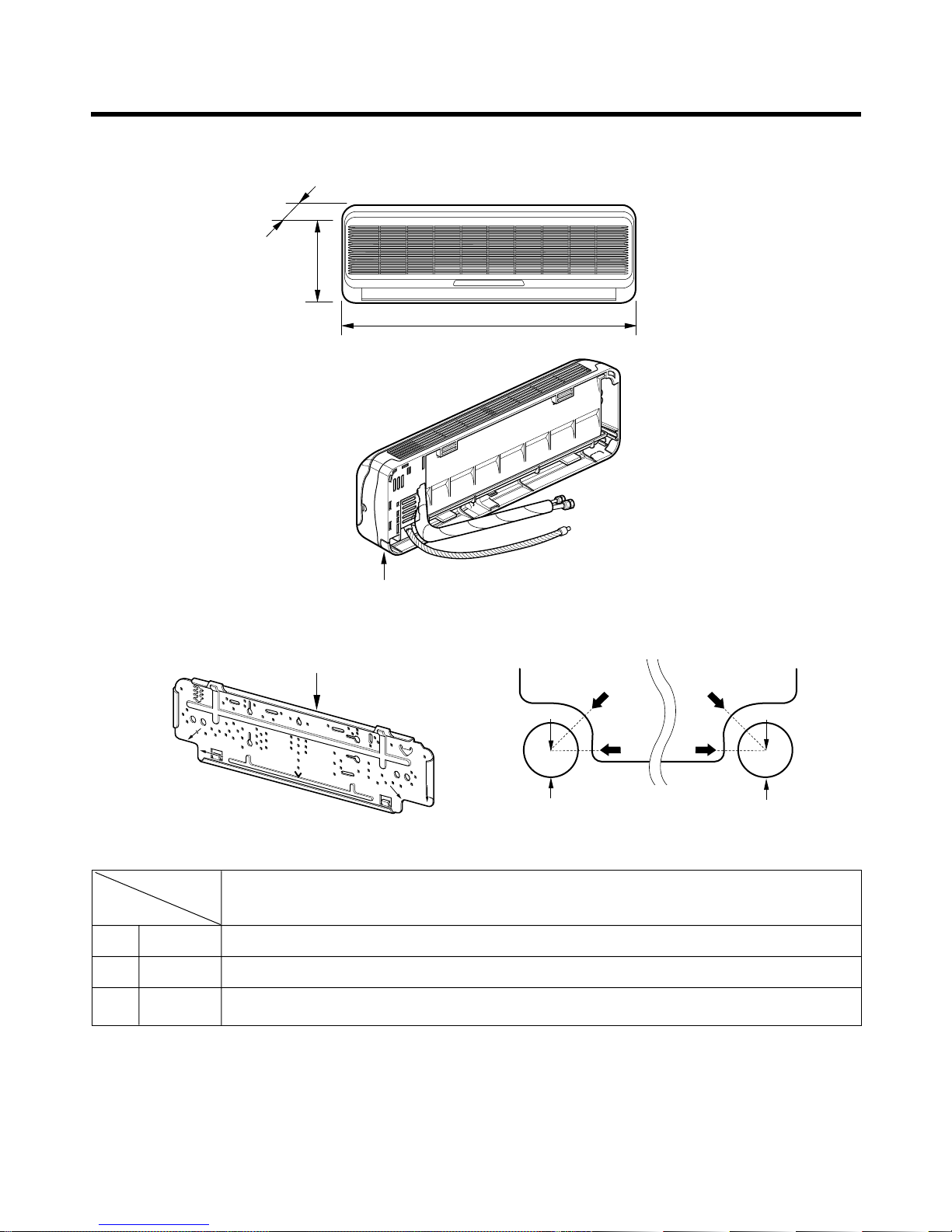
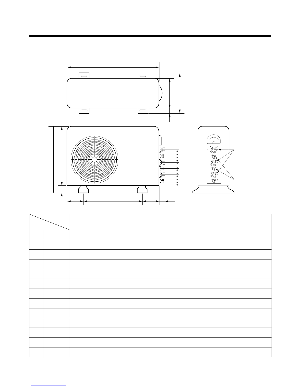
Dimensions
Installation plate
A
A
ø70mm
Center
Center
ø70mm
Left rear piping Right rear piping
A
A
D
H
W
Tubing hole cover
Wmm 888
Hmm 287
Dmm 170
LM-2421C2L/A2L
LM-3022C3L/A3L
MODEL
DIM
1. Indoor Unit
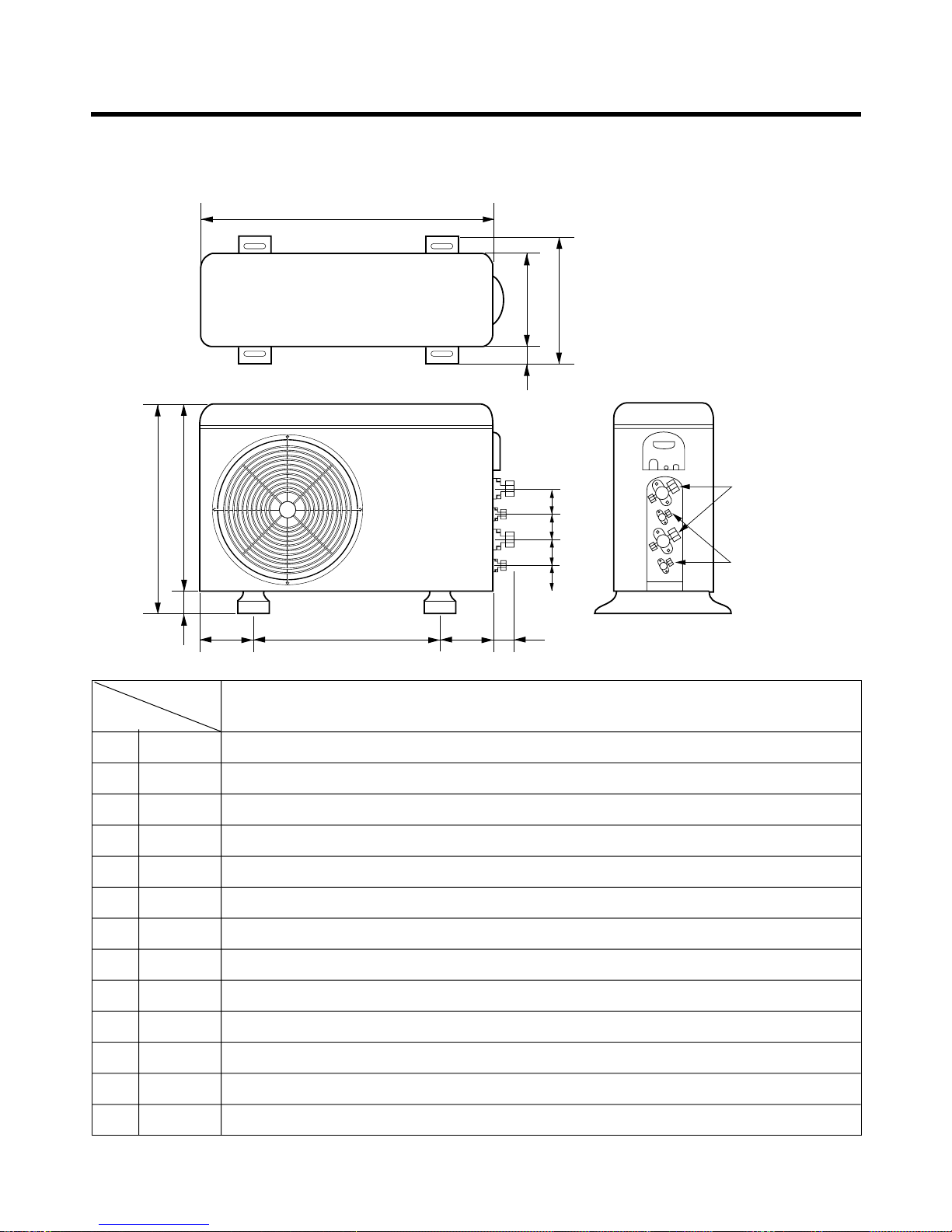
-7-
W
D
L1
L2
L9
L4
L3
H
L10
L10
L10
L8
Gas side
3-Way valve
Liquid side
2-Way valve
L7L5L6
2. Outdoor Unit
2-1. LM-2421C2L/A2L
W mm 870
H mm 655
D mm 320
L1 mm 370
L2 mm 25
L3 mm 630
L4 mm 25
L5 mm 546
L6 mm 160
L7 mm 160
L8 mm 64
L9 mm 76.5
L10 mm 50
LM-2421C2L
LM-2421A2L
MODEL
DIM
-8-
W
L5L6 L7 L8
L3
H
D
L1
L2
L4
L10L9
Gas side
3-way valve
Liquid side
2-way valve
L10L10L10L10
W mm 870
H mm 655
D mm 320
L1 mm 370
L2 mm 25
L3 mm 630
L4 mm 25
L5 mm 546
L6 mm 160
L7 mm 160
L8 mm 64
L9 mm 76.5
L10 mm 50
LM-3022C3L
LM-3022A3L
MODEL
DIM
2-2. LM-3022C3L/A3L
-9-
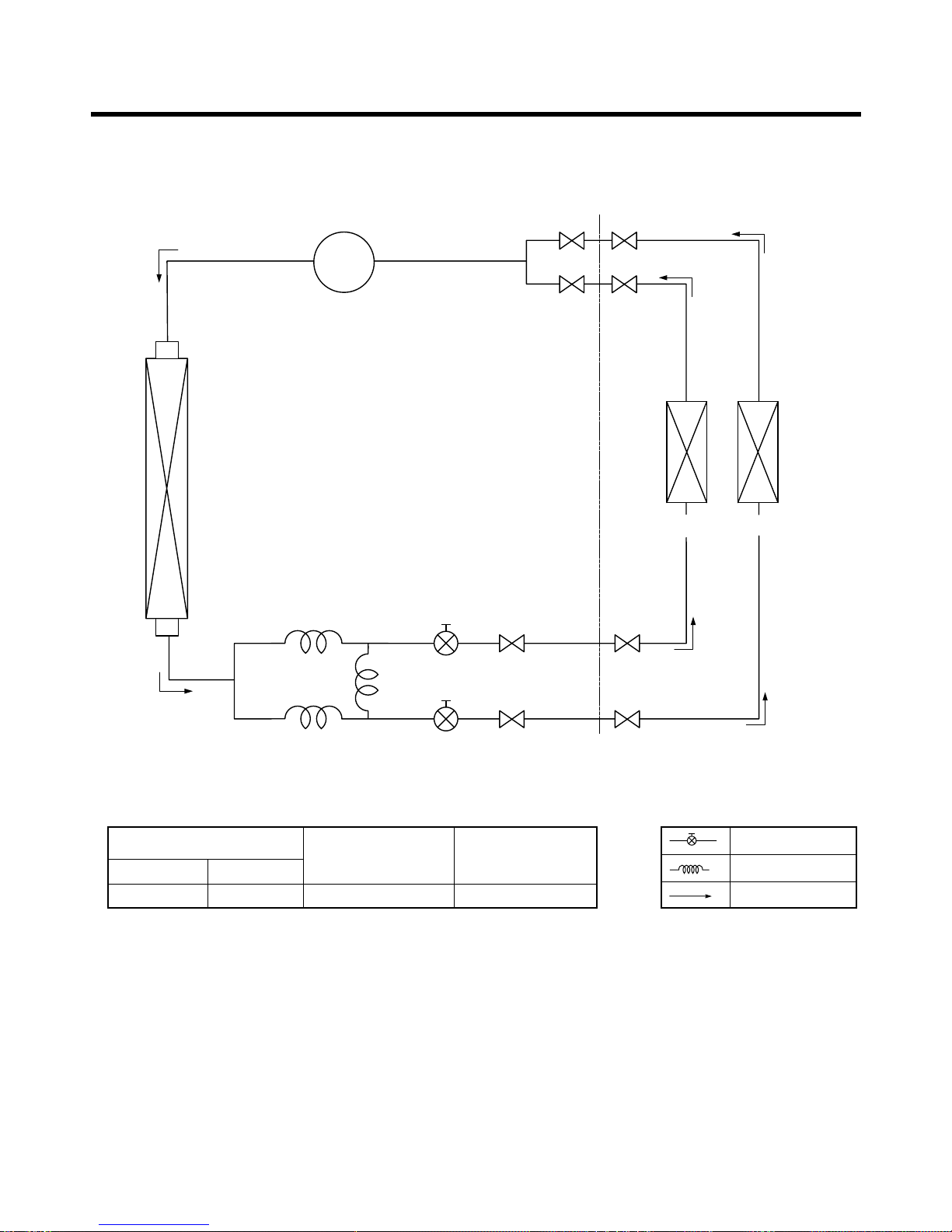
Refrigeration Cycle Diagram
COMP
3-WAY
Valve
ø6.35
ø12.7
ø12.7
ø6.35
HEAT
EXCHANGER
HEAT
EXCHANGER
(A Unit) (B Unit)
Pipe Size (Diameter : inch)
Max.
piping length
(m)
Max.
piping elevation
(m)
Gas Liquid
1/2" 1/4" 10~15 5~7
ex)
Solenoid Valve
Capillary
Cooling
1. LM-2421C2L/A2L
-10-
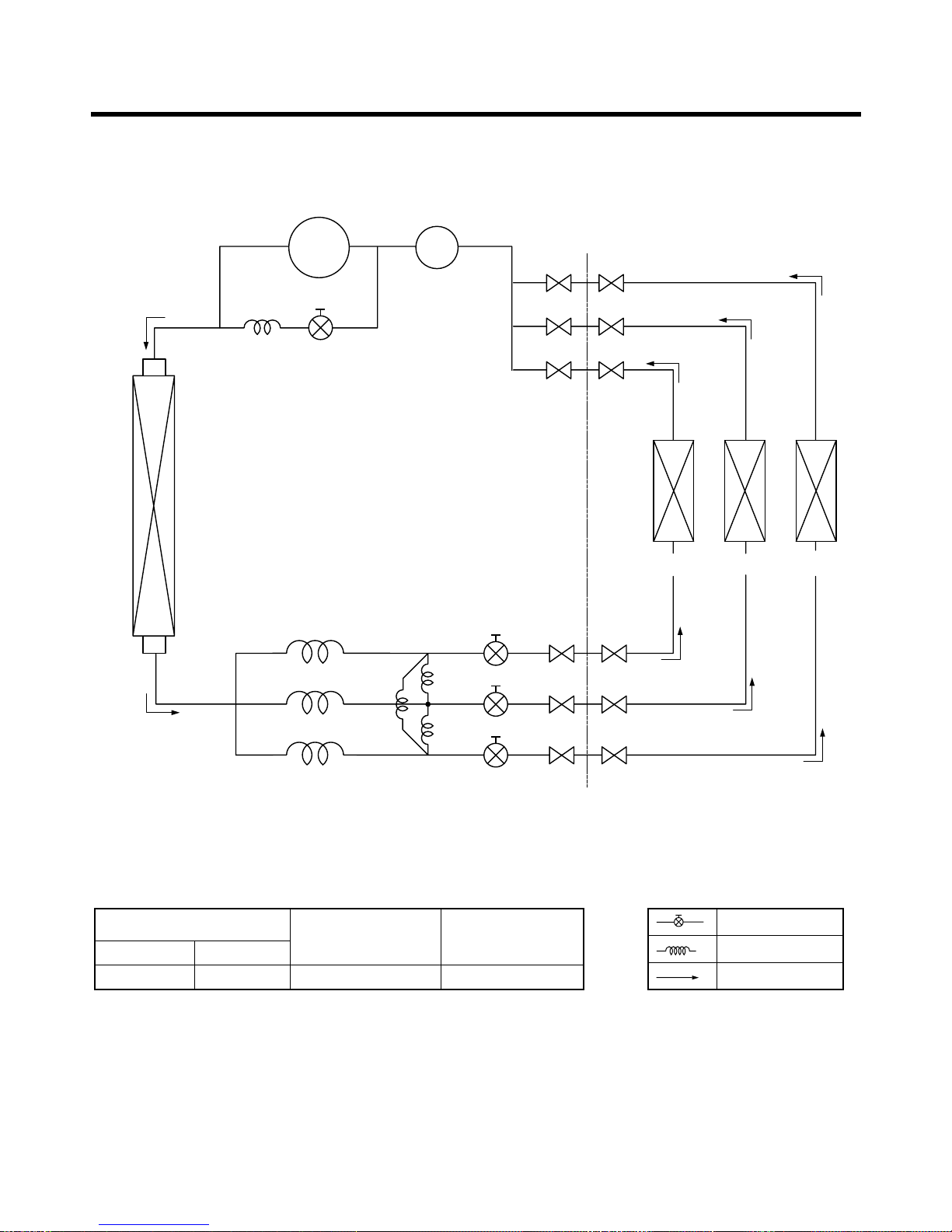
2. LM-3022C3L/A3L
COMP
3-WAY
Valve
2-WAY
Valve
ACCUMUIATOR
ø6.35
ø12.7
ø12.7
ø12.7
ø6.35
ø6.35
HEAT
EXCHANGER
HEAT
EXCHANGER
(A Unit) (B Unit) (C Unit)
Pipe Size (Diameter : inch)
Max.
piping length
(m)
Max.
piping elevation
(m)
Gas Liquid
1/2" 1/4" 10~15 5~7
ex)
Solenoid Valve
Capillary
Cooling
-11-
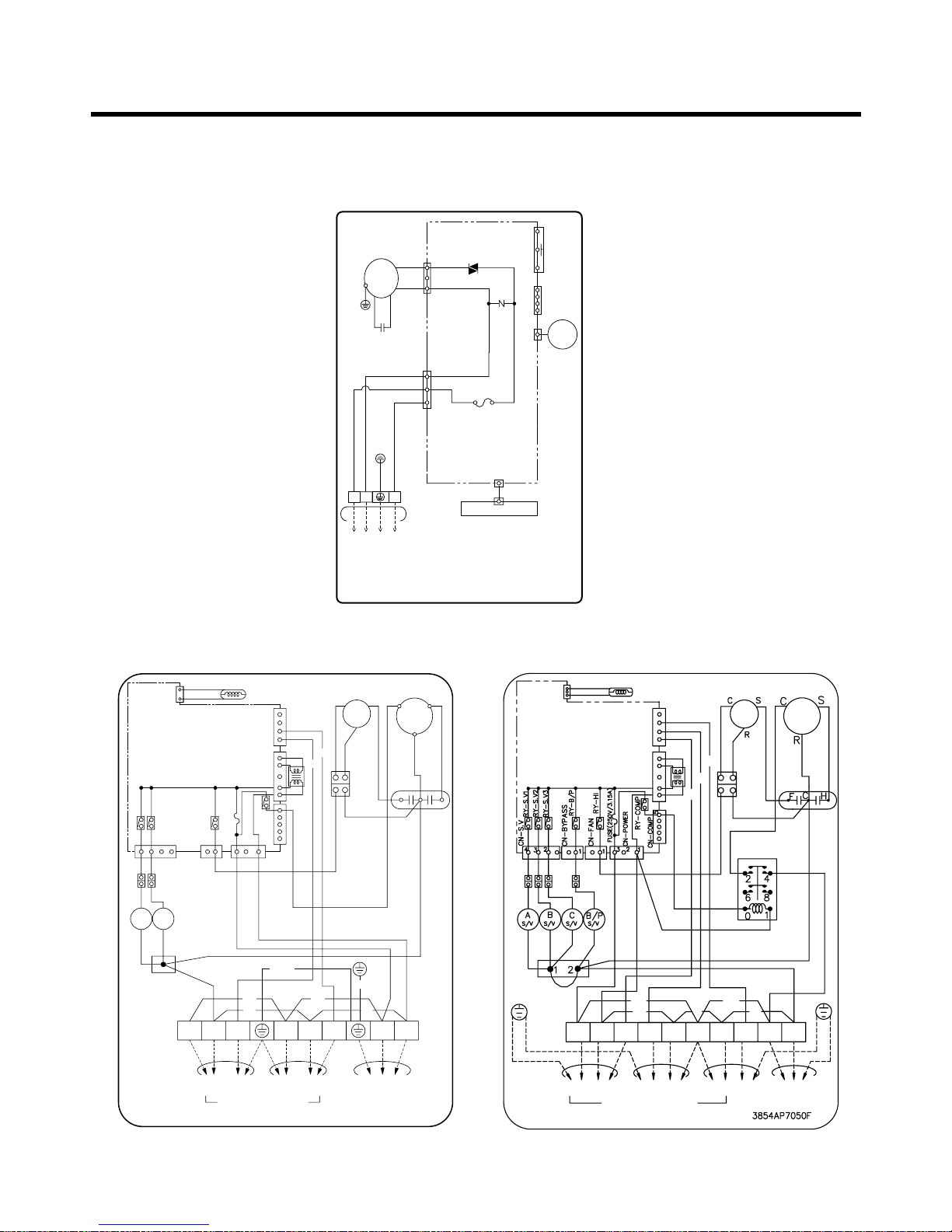
Wiring Diagram(Cooling Only)
1-1. Indoor Unit
(LM-2421C2L/A2L, LM-3022C3L/A3L)
1-2. Outdoor Unit
• LM-2421C2L/A2L • LM-3022C3L/A3L
3854A20023B
INDOOR WIRING DIAGRAM
CN-DISP1
CN-U/D
FUSE
AC250V/T2A
CN-TH
SSR
SH-CAPA.
BR
YL
OR
BK
CN-POWER CN-FAN
ZNR
THERMISTOR
FORCED
OPERATION
AUTO
RESTART
REMOTE
CONTROL
STEP
MOTOR
MOTOR
MAIN PCB
ASM
DISPLAY PCB ASM
TO OUTDOOR UNIT
PILLAR
TERMINAL
BR
BL
YL
1(L) 2(N
)
3
THERMISTOR
CN-TH
RD
BL
BR
BR
YL BK
BK BK
BK
BK
BK
BK
GN/YL
GN/YL
TERMINAL
BLOCK(10P)
T/BLOCK
1(L)
A-UNIT B-UNIT
TO INDOOR UNIT
OUTDOOOR WIRING DIAGRAM
C-UNIT MAIN
POWER
1(L)1(L)2(N) 2(N)33 32(N) 2(N)
BK BK
BK
BK
BK
OR
OR
YL
RELAY
CAPA.
MOTOR
COMP
WH
WHWH
WH
BL
BL BL BL BL
WH WH
RD
C
B
A
CN-COM
CN-TRANS
TRANS FORMER
MAIN P.C.B. ASM
CN-TH
CCS
R
F
TERMINAL
BLOCK(
10P)
1(L
)
2(N
)
2(N
)
1(L
)
31
(L)2(N)
3
A-UNIT
T/BLOCK
BL BL
BK
BK
TRANS FORMER
OR
THERMISTOR
YL
OR BK BR
WH
CAPA.
BK
MOTOR
COMP
BK
WH
BLYL
BK
B-UNIT
TO INDOOR UNIT
OUTDOOR WIRING DIAGRAM
3854A30076L
MAIN
POWER
A
CH
R
S
B
A
5
7
CN-COM
CN-TRANSCN-COMP
CN-POWER
RY-COMP
CN-S.V
S/VBS/V
CN-FAN
RY-S.V1
RY-S.V2
432 11321
5
RY-HI
FUSE(250V/3.15A)
MAIN P.C.B ASM
BK BK
WH
WH
WH
BL
BR
GN/YL
GN/YL
-12-
Operation Details
1. MAIN UNIT FUNCTION
• DISPLAY
• On while in appliance operation, off while in appliance pause
• Flashing while in disconnection or short in Thermistor (3 sec off / 0.5 sec on)
• On while in healthy dehumidification mode, off when healthy dehumdification is cancelled.
• On while in timer mode (on/off), off when timer mode is completed or canceled.
• While in appliance operation, on while in outdoor unit compressor running, off while in compressor off
■ Cooling Mode Operation
•
When the intake air temperature reaches 0.5°C below the setting temp, the compressor and the outdoor fan stop.
• When it reaches 0.5°C above the setting temp, they start to operate again.
Compressor ON Temp ➲ Setting Temp+0.5°C
Compressor OFF Temp ➲ Setting Temp-0.5°C
• While in compressor running, operating with the airflow speed set by the remote control. While in compressor not running, operating with the low airflow speed regardless of the setting.
■ Healthy Dehumidification Mode
• When the dehumidification operation input by the remote control is received, the intake air temperature is
detected and the setting temp is automatically set according to the intake air temperature.
26°C ≤ Intake Air Temp ➲ 25°C
24°C ≤ Intake Intake Air Temp<26°C ➲ Intake Air Temp-1°C
18°C ≤ Intake Intake Air Temp<24°C ➲ Intake Air Temp-0.5°C
Intake Air Temp<18°C ➲ 18°C
• While in compressor off, the indoor fan repeats low airflow speed and pause.
• While the intake air temp is between compressor on temp. and compressor off temp., 10-min dehumidifica-
tion operation and 4-min compressor off repeat.
Compressor ON Temp. ➲ Setting Temp+0.5°C
Compressor OFF Temp. ➲ Setting Temp-0.5°C
• In 10-min dehumidification operation, the indoor fan operates with the low airflow speed.
■ Cooling overload
• Outdoor fan ON/OFF by sensing outdoor pipe temperature.
• Outdoor fan is OFF if pipe temperature is below 0°C and outdoor fan is ON if pipe temperature is over 0°C.
■ Airflow Speed Selection
• The airflow speed of the indoor fan is set to high, low by the input of the airflow speed selection key on the
remote control.
■ Off-Timer Operation
• When the set time is reached after the time is input by the remote control, the appliance stops operating.
• The timer LED is on when the off-timer is input. It is off when the time set by the timer is reached.
• If the appliance is on pause at the time set by the timer, the pause continues.
Comp. Running Incidator
Timer Indicator
Soft Dry Indicator
Operation Indicator
-13-
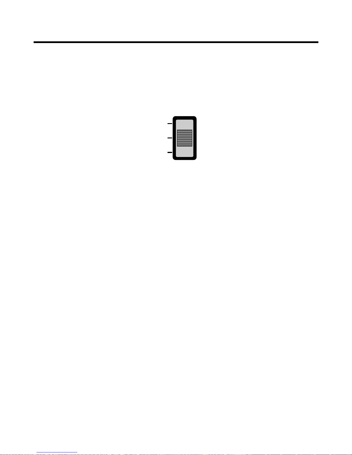
■ Auto Restarting Operation
• When the power is restored after a sudden power failure while in appliance operation, the mode before the
power failure is kept on the memory and the appliance automatically operates in the mode on the memory.
• The slide switch on the main unit of the appliance should be on the Auto Restarting position in order that
the Auto Restarting operation is available.
• Operation Mode that is kept on the memory
- State of Operation ON/OFF
- Operation Mode/Setting Temp/Selected Airflow Speed
Slide Switch
FORCED
OPERATION
AUTO
RESTART
REMOTE
CONTROL
■ Forced Operation (C/O Model)
• To operate the appliance by force in case that the remote control is lost, the forced operation selection
switch is on the main unit of the appliance to operate the appliance in the standard conditions.
• When the power is supplied while the slide switch is on the forced operation position, or when the slide
switch position is switched to the Auto Restarting position (or test operation) or switched from the remote
control position to the forced operation position while the power is on, the forced operation is carried out.
• When the slide switch position is switched from the forced operation position to the Auto Restarting position
or the remote control position, the forced operation is canceled and the appliance stops operating.
• The forced operation is carried out in cooling mode with the setting temperature 22°C and the high speed of
airflow.
• While in forced operation, the key input by the remote control has no effect and the buzzer sounds 10 times
to indicate the forced operation.
■ Remote Control Operation Mode
• When the remote control is selected by the slide switch on the main unit, the appliance operates according
to the input by the remote control.
■ Protection of the evaporator pipe from frosting
• If the indoor pipe temp is below 0°C in 7 min. after the compressor operates without any pause while in
cooling cycle operation mode, the compressor and the outdoor fan are turned off in order to protect the
indoor evaporator pipe from frosting.
• When the indoor pipe temp is 7°C or higher after 3 min. pause of the compressor, the compressor and the
outdoor fan is turned on according to the condition of the room temperature.
■ Buzzer Sounding Operation
• When the appliance-operation key is input by the remote control, the short "beep-beep-" sounds.
• When the appliance-pause key is input by the remote control, the long "beep—" sounds.
• When a key is input by the remote control while the slide switch on the main unit of the appliance is on the
forced operation position, the error sound "beep-beep-beep-beep-beep-" is made 10 times to indicate that
the remote control signal cannot be received.
Cooling Model
• Operation
• Timer Mode
• Soft Dry Mode
• Outdoor Unit Operating or not
-14-
Display Function
Operation Indicator
Timer Indicator
Soft Dry Indicator
Outdoor Unit Operation
OUT
DOOR
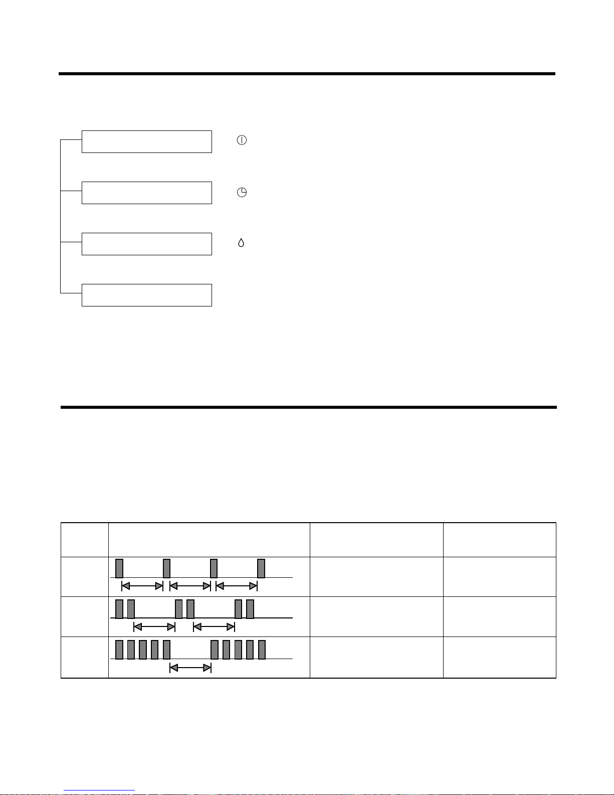
Self-diagnosis Function
1
(once)
(twice)
(5times)
3sec 3sec
3sec
3sec
3sec
3sec
2
3
Error
Code
Error LED
(Indoor body operation LED)
Error contents SVC check point
• Indoor suction temperature
thermistor open/short.
• Indoor pipe temperature
thermistor open/short.
• Indoor TH ass'y check
• Outdoor TH ass'y
check
• Communication
line/circuit check
• Outdoor suction temperature
thermistor open/short.
• Outdoor pipe temperature
thermistor open/short.
• Poor communication
■ Error Indicator
• The function is to self-diagnoisis airconditioner and express the troubles identifically if there is any trouble.
• Error mark is ON/OFF for the operation LED of evaporator body in the same manner as the following table.
• If more than two troubles occur simultaneously, primarily the highest trouble fo error code is expressed.
• After error occurrence, if error is released, error LED is also released simultaneously.
• To operate again on the occurrence of error code 12, be sure to pull out power cord and then re-insert.
-15-
Installation
Front
Right Rear right
Rear left
Down right
Left
More than 5 cm
More than eye-level
More than
5 cm
More than
5 cm
More than 10 cm
More than 10 cm
More than
70 cm
A
B
Indoor unit
Outdoor unit
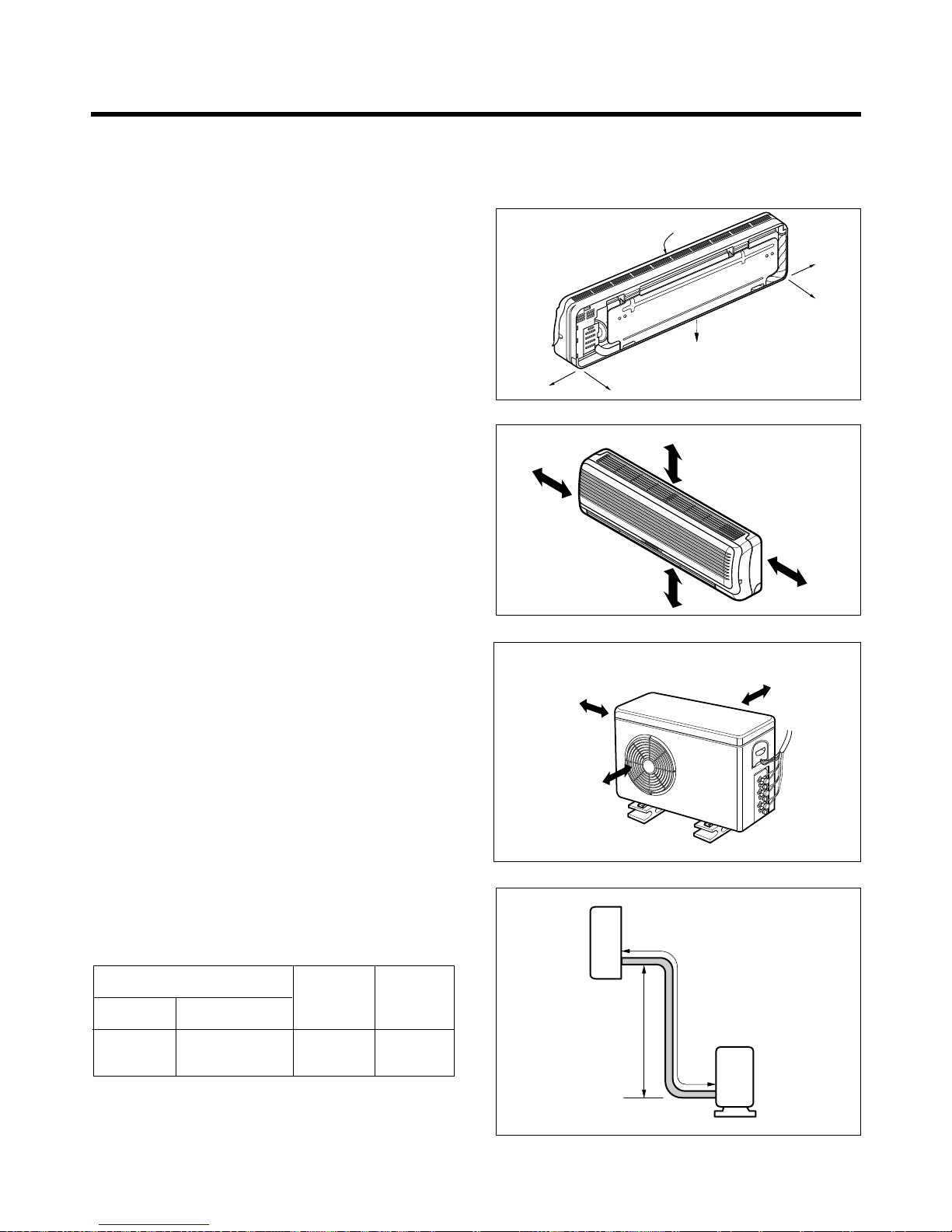
1) Selection of the best location
1. Indoor unit
• There should not be any heat source or steam
near the unit.
• There should not be any obstacles to prevent
the air circulation.
• A place where air circulation in the room will be
good.
• A place where drainage can be easily obtained.
• A place where noise prevention is taken into
consideration.
• Do not install the unit near the door way.
• Ensure the spaces indicated by arrows from
the wall, ceiling, fence, or other obstacles.
2. Outdoor unit
• If an awning is built over the unit to prevent
direct sunlight or rain exposure, be careful that
heat radiation from the condenser is not
restricted.
• There should not be any animals or plants
which could be affected by hot air discharged.
• Ensure the spaces indicated by arrows from
the wall, ceiling, fence, or other obstacles.
3. Piping length and the elevation
Pipe Size
GAS LIQUID
Max. piping
length
A(m)
Max.
Elevation
B (m)
1/2" 1/4" 10~15 5~7
(1) Installation of Indoor, Outdoor unit
-16-
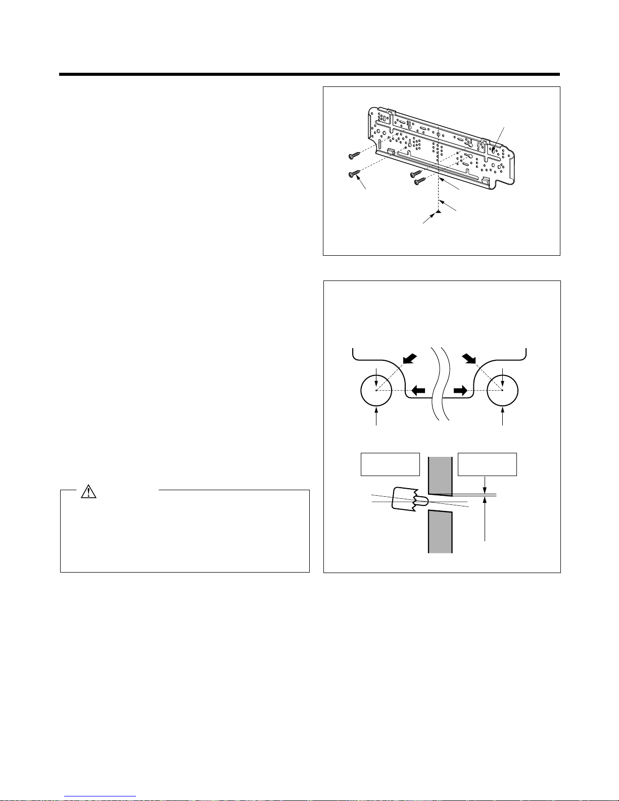
2) Indoor Unit Installation
The mounting wall should be strong and solid
enough to protect it from the vibration.
1. Mount the installation plate on the wall with
four Type "A" screws.
(If mounting the unit on the concrete wall, consider using anchor bolts.)
• Always mount the Installation plate horizontally
by aligning the marking-off line by means of the
thread and a level.
2. Drill the piping hole with 70mm dia. holecore
drill.
• Line according to the arrows marked on lower
the left and the rght side of the Installation Plate.
The meeting point of the extended line is the
center of the hole.
• Drill the piping hole at either the right or the left
and the hole should be slightly slant to the outdoor side.
Installation Plate
marking-off line
Thread
Weight
Type "A" screw
ø70mm ø70mm
5~7mm
A
A
A
A
Indoor Outdoor
Wall
Left rear piping Right rear piping
9K, 10K, 12K BTU
The lower left and the right side of
Installation Plate
Center
Center
1. After installation, remove a piece of insulation at the
slide switch.
2.After installation or service, confirm that the slide
switch is at "REMOTE CONTROL"
CAUTION
-17-
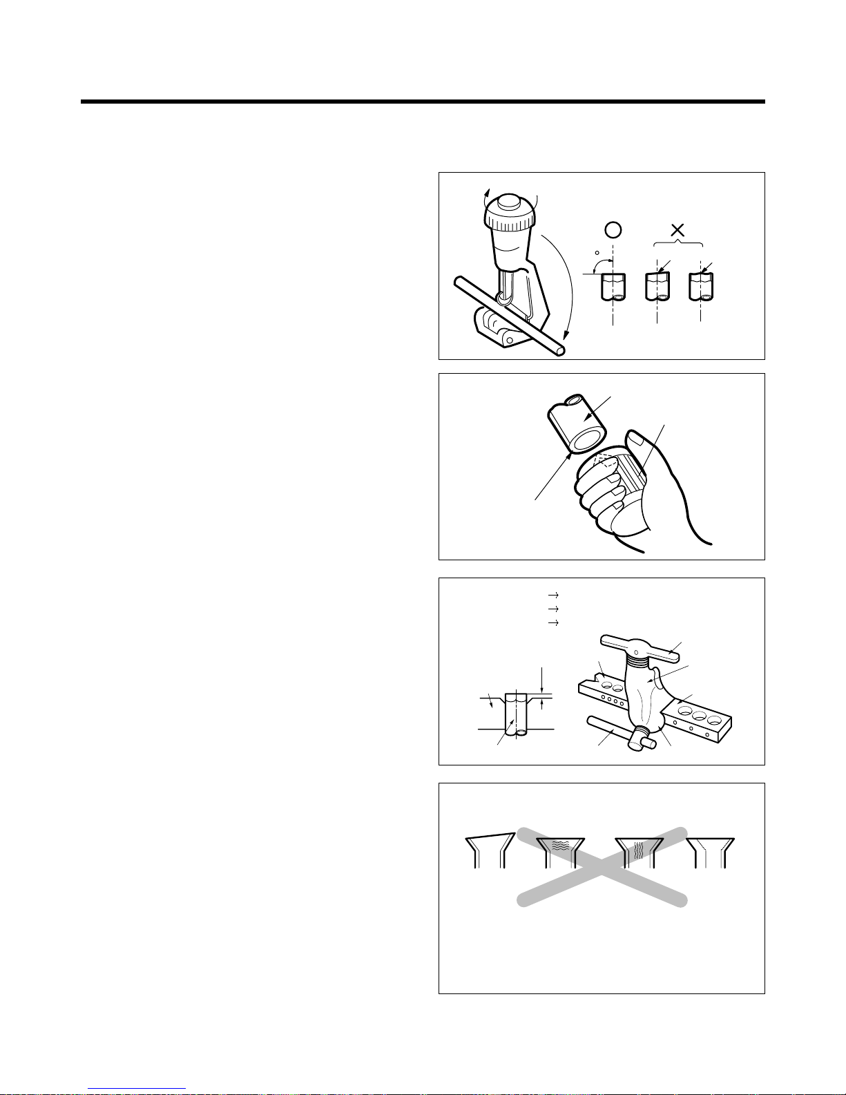
1) Preparation of pipings
1. Cut the pipes and the cable.
• Use the accessory piping kit or the pipes
purchased locally.
• Measure the distance between the indoor and
the outdoor unit.
• Cut the pipes a little longer than the measured
distance.
• Cut the cable 1.5m longer than the length of the
pipe.
2. Remove burrs.
• Remove burrs from cut edges of pipes.
• Turn the pipe end toward down to avoid the
metal powder entering the pipe.
Caution:
If burrs are not removed, they may cause a gas
leakage.
3. Flaring the pipes.
• Insert the flare nuts, mounted on the connection
ports of both indoor and outdoor unit, onto the
copper pipes. Some refrgerant gas may leak,
when the flare nuts are removed from the indoor
unit, as some gas is charged to prevent the
inside of the pipe from rusting.
• Fit the copper pipe end into the Bar of flare tool
about 0~0.5mm higher. (See illustration)
• Flare the pipe ends.
4. Tape the flaring portion to protect it from the
dust or damages.
90
Slanted
Pipe cutter
Rough
Reamer
Pipe
Point down
"A"
Bar
Copper pipe
Clamp handle
Red arrow mark
Cone
Bar
Yoke
Handle
Inclined Cracked Uneven
thickness
Surface
damaged
= Improper flaring =
When properly flared, the internal surface flare will
evenly shine and be of even thickness.
Since the flare part comes into contact with the connectors, carefully check the flare finish.
"
A"; ø12.7mm (1/2") 0~0.5mm
ø9.52mm (3/8")
0~0.5 mm
ø6.35mm (1/4")
0~0.5 mm
(2) Piping and Drainage of Indoor Unit
 Loading...