

LG LM-230W01-A2P3 Service manual
www.DataSheet4U.net
www.DataSheet4U.net
LM230W01
Liquid Crystal Display
Product Specification
www.jxlcd.com
www.jxlcd.com
Ver. 1.0 FEB . 06 . 2003
1 / 27
www.DataSheet4U.net
www.DataSheet4U.net
LM230W01
Liquid Crystal Display
Product Specification
Contents
PageITEMNo
COVER
CONTENTS
RECORD OF REVISIONS
GENERAL DESCRIPTION1
ABSOLUTE MAXIMUM RATINGS2
ELECTRICAL SPECIFICATIONS3
ELECTRICAL CHARACTREISTICS 3-1
INTERFACE CONNECTIONS 3-2
SIGNAL TIMING SPECIFICATIONS 3-3
SIGNAL TIMING WAVEFORMS 3-4
COLOR INPUT DATA REFERNECE 3-5
www.jxlcd.com
www.jxlcd.com
POWER SEQUENCE 3-6
OPTICAL SFECIFICATIONS4
MECHANICAL CHARACTERISTICS5
RELIABLITY6
1
2
3
4
5
6
6
8
11
12
13
14
15
19
22
Ver. 1.0 FEB . 06 . 2003
INTERNATIONAL STANDARDS7
SAFETY 7-1
EMC 7-2
PACKING8
DESIGNATION OF LOT MARK 8-1
PACKING FORM 8-2
23
23
23
24
24
24
25PRECAUTIONS9
27APPENDIX
2 / 27
www.DataSheet4U.net
www.DataSheet4U.net
LM230W01
Liquid Crystal Display
Product Specification
RECORD OF REVISIONS
DESCRIPTIONPageRevision DateRevision No
First Draft (Preliminary)-JAN.17.20030.0
the White color coordination change ( TBD,TBD →0.314,0.331)15FEB.06.20031.0
www.jxlcd.com
www.jxlcd.com
Ver. 1.0 FEB . 06 . 2003
3 / 27
www.DataSheet4U.net
www.DataSheet4U.net
LM230W01
Liquid Crystal Display
Product Specification
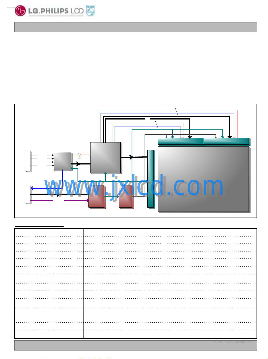
1. General Description
The LM230W01 LCD is a Color Active Matrix Liquid Crystal Display with an integral Cold Cathode Fluorescent
Lamp(CCFL) back light system. The matrix employs a-Si Thin Film Transistor as the active element. It is a tra
nsmissive type display operating in the normally black mode. This TFT-LCD has a 23.0 inch diagonally measu
red active display area with WUXGA resolution(1920 vertical by 1200 horizontal pixel array). Each pixel is divid
ed into Red, Green and Blue sub-pixels or dots which are arranged in vertical stripes. Gray scale or the lumina
nce of the sub-pixel color is determined with a 8-bit gray scale signal for each dot, thus, presenting a palette of
more than 16,777,216 colors.
The LM230W01 has been designed to apply the TMDS
erface method to enables a simple and low-cost implementation in both the host and monitor.
TM
(Transition Minimized differential Signaling) as the int
RGB (24BIT)
CLK
RGB (24B IT)
VCC, VDD
V0~ V1 7
SOURCE (Left)
SOURCE (Right)
RXC +/RX0 +/RX1 +/-
(2 0 P IN)
USER C ON
POW ER C ON
RX2 +/-
H sync, Vsyn c
(15P IN)
TM D S
TM D S
TM D STM D S
Receiver
Receiver
ReceiverR eceiver
IN P U T 1 8V
www.jxlcd.com
www.jxlcd.com
PW R _O N
General Features
RGB D ATA
CLK
Hsync
Vsyn c
Tim ing
Tim ing
Tim ingTim ing
C o n t r o lle r
C o n t r o lle r
C o n t r o lle rC o n t r o lle r
DC/DC
DC/DC
DC/DCDC/DC
C onverter
C onverter
C onverterC onverter
23.0 inches(58.4cm) diagonalActive Screen Size
550.0(H) x 360.5(V) x 25.0(D) mm(Typ.)Outline Dimension
495.36[mm] × 309.6[mm]Active Area
0.258 mm x 0.258mmPixel Pitch
1920 horiz. By 1200 vert. Pixels RGB stripes arrangementPixel Format
8-bit, 16,777,216 colorsColor Depth
200 cd/m
Total 47 Watt(Typ.)Power Consumption
4,500 g (typ.)Weight
K
L
C
PANEL
PANEL
G
A
VC C
T
VG H ,VG L
GAMMA
GAMMA
GAMMAGAMMA
2
(Typ.)Luminance, White
E
PANELPANEL
1920 X 1200
1920 X 1200
1920 X 12001920 X 1200
Surface Treatment
Ver. 1.0 FEB . 06 . 2003
Transmissive mode, normally blackDisplay Operating Mode
Hard coating(3H)
Anti-glare treatment of the front polarizer,
TMDS (Hsync/DE)Interface
6 CCFL’s(Cold Cathode Fluorescent Lamp)LAMP
4 / 27
www.DataSheet4U.net
www.DataSheet4U.net
Liquid Crystal Display
Product Specification
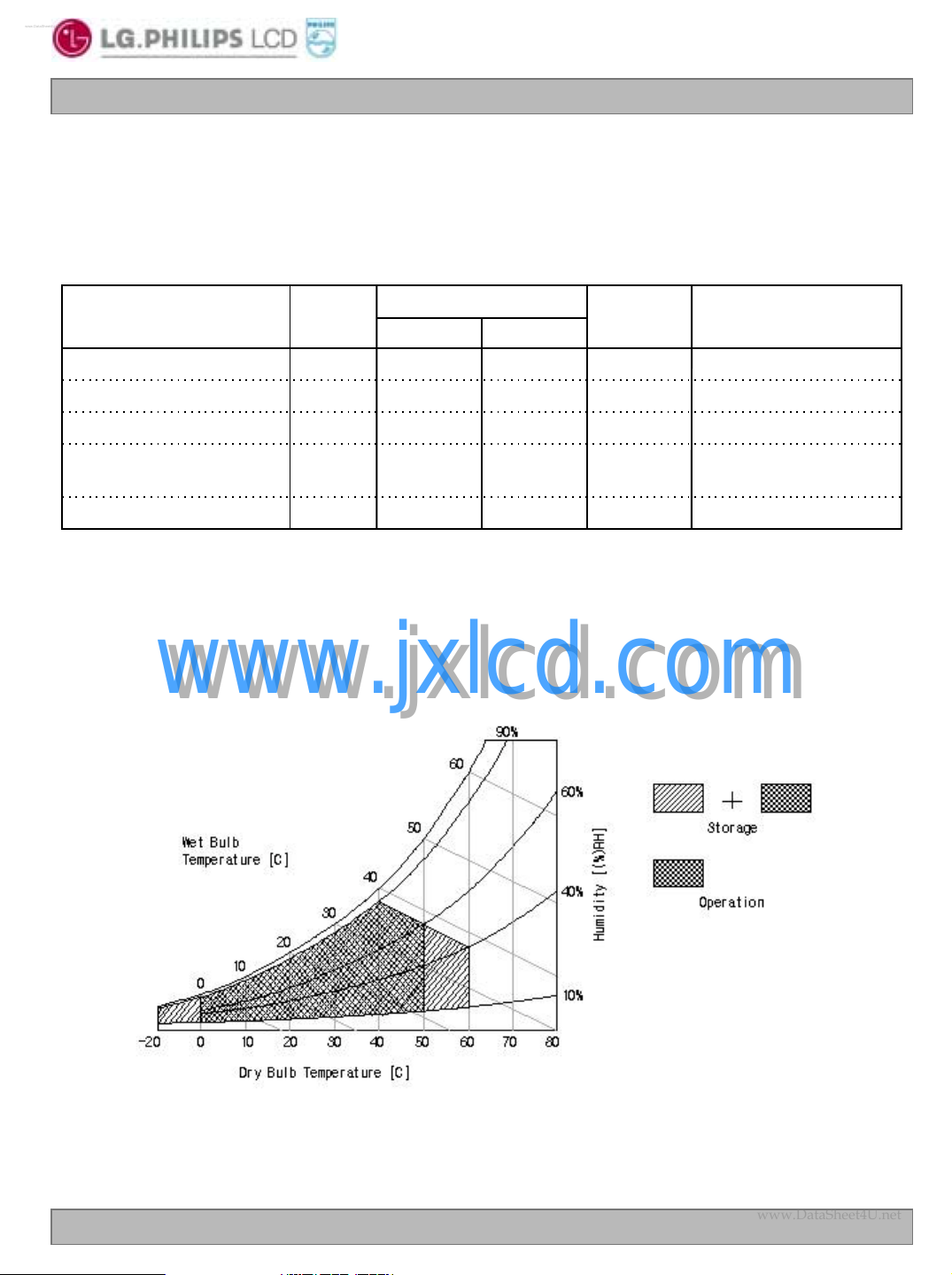
2. Absolute Maximum Ratin gs
The following are maximum values which, if exceeded, may cause operation or damage to the unit.
Table 1. ABSOLUTE MAXIMUM RATINGS
LM230W01
Parameter Notes
Power Input Voltage
Operating Temperature
Storage Temperature
Operating Ambient Humidit
y
Storage Humidity
Note : 1. Temperature and relative humidity range are shown in the figure below.
Wet bulb temperature should be 39 °C Max, and no condensation of water.
www.jxlcd.com
www.jxlcd.com
Symbol
OP
ST
OP
ST
Values
MaxMin
500T
60-20H
Units
°C
°C
at 25 ± 5°CVcc21-0.3Vcc
1
1
1%RH9010H
1%RH9010H
Ver. 1.0 FEB . 06 . 2003
5 / 27
www.DataSheet4U.net
www.DataSheet4U.net
Liquid Crystal Display
Product Specification
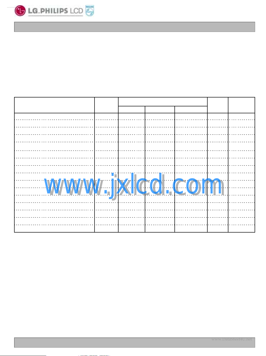
3. Electrical Specifications
3-1. Electrical Characteristics
The LM230W01 requires two power inputs. One input is employed to power the LCD electronics and to d
rive the voltages to drive the TFT array and liquid crystal. And the second input which powers the CCFL, i
s typically generated by an inverter. The inverter is an external unit to the LCD.
Table 2. ELECTRICAL CHARACTERISTICS
LM230W01
Parameter Symbol
MODULE :
Inrush Current
LAMP :
Operating Voltage
Operating Current
at 25 °C
www.jxlcd.com
www.jxlcd.com
at 0 °C
Operating Frequency
Power Consumption
Notes : 1. The input current shall be measured at V
clock frequency of 156MHz under mosaic pattern(8x6) (typ).
2. The measuring condition
The duration of rush current is about 20ms, and rising time of Power input is 1ms.
3. The variance of the voltage is ±10%.
4. Operating voltage is measured at 25°C. The variance of the voltage is ±10%.
5. The output voltage at the transformer in the inverter must be high considering to the loss of the
ballast capacitor in the inverter. The voltage above V
than 1 second for start-up. Otherwise, the lamps may not be turned on.
6. Lamp frequency may produce interface with horizontal synchronous frequency and as a result this
may cause beat on the display. Therefore lamp frequency shall be as away possible from the
horizontal synchronous frequency and from its harmonics in order to prevent interference.
7. The lamp power consumption shown above does not include loss of external inverter at 25°C.
The used lamp current is the lamp typical current.
Rush
BL
BL
BL
BL
of 18.0Vdc at 25℃, refresh rate of 60Hz, and pixel
CC
Values
MaxTypMin
Vdc19.018.017.0Vcc Power Supply Input Voltage
1090(2.5mA)875(7.5mA)830(9mA)V
1400-1960--
should be applied to the lamps for more
S
V
V
RMS
mA9.07.52.5I
RMS
RMS
NotesUnit
1A0.650.45-Icc Power Supply Input Current
1Watt11.78.1-Pc Power Consumption
2A3--I
3V
4Vs Established Starting Voltage
5kHz605040F
6Watt45.141.0-P
7min3--Ts Discharge Stabilization Time
8Hrs30,000 Life Time
Ver. 1.0 FEB . 06 . 2003
6 / 27
www.DataSheet4U.net
www.DataSheet4U.net
Liquid Crystal Display
LM230W01
Product Specification
8. Let’s define the brightness of the lamp after being lighted for 5 minutes as 100%.
T
The used lamp current is the lamp typical current.
9. The life time is defined as the time at which brightness of lamp is 50% compare to that of initial
value at the typical lamp current on condition of continuous operating at 25±2°C.
Note. Do not attach a conducting tape to connecting wire.
If the lamp wire attach to a conducting tape, TFT-LCD Module has a low luminance and the
inverter has abnormal action. Because leakage current is occurred between lamp wire and
conducting tape.
is the time required for the brightness of the center of the lamp to be not less than 95%.
S
The design of the inverter must have specifications for the lamp in LCD Assembly.
The performance of the Lamp in LCM, for example life time or brightness, is extremely influenced by
the characteristics of the DC-AC inverter. So all the parameters of an inverter should be carefully
designed so as not to produce too much leakage current from high-voltage output of the inverter.
When you design or order the inverter, please make sure unwanted lighting caused by the mismatch
of the lamp and the inverter(no lighting, flicker, etc) never occurs. When you confirm it, the LCD –
Assembly should be operated in the same condition as installed in you instrument.
Requirements for a system inverter design, which is intended to have a better display performance, a
better power efficiency and a more reliable lamp.
It shall help increase the lamp lifetime and reduce its leakage current.
a. The asymmetry rate of the inverter current and voltage waveform should be 10% below;
b. The distortion rate of the current and voltage waveform should be within √2 ±10%;
c. The ideal sine current and voltage waveform shall be symmetric in positive and negative polarities.
* Asymmetry rate = | I
* Distortion rate = I
www.jxlcd.com
www.jxlcd.com
– I –p | / I
p
(or I –p) / I
p
rms
rms
* 100%
Ver. 1.0 FEB . 06 . 2003
7 / 27

www.DataSheet4U.net
www.DataSheet4U.net
Liquid Crystal Display
LM230W01
Product Specification
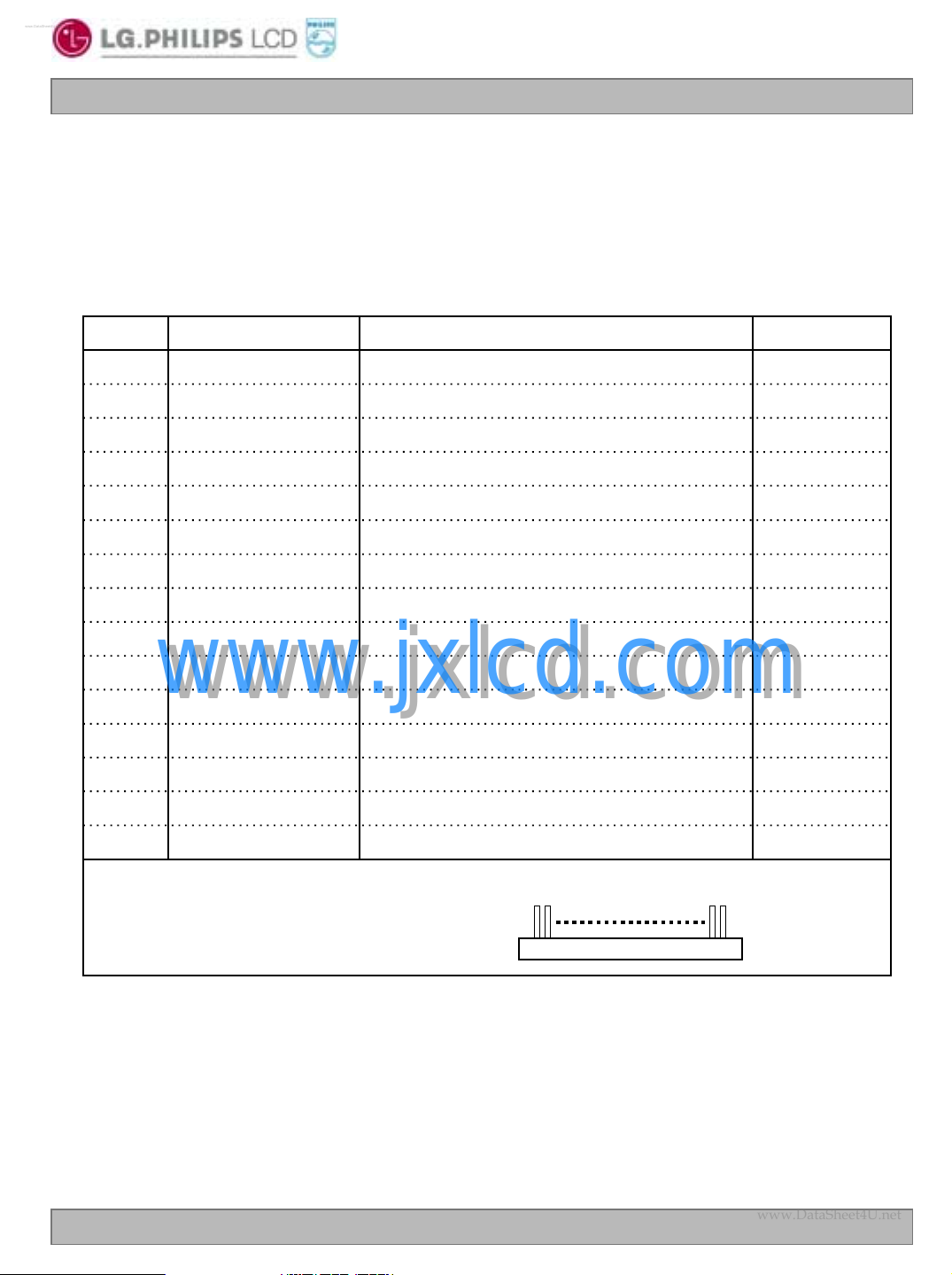
3-2. Interface Connections
This LCD employs three kinds of interface connections. A 20 pin connector is used for TMDS signals from t
he host computer. A 15-pin connector is used for LCD module power and LCM controls signal from external
monitor control circuits. And six connectors, two pin connector, are used for the integral backlight system.
3-2-1. Sig nal Interface
The TMDS signal interface connector is FI-XL20S-HF by JAE.
The pin configuration for the 20 pin connector is shown in the table below.
Table 3 20PIN CONNECTOR (CNC6) PIN CONFIGURATION
DescriptionSymbolPinDescriptionSymbolPin
GND Shield for TMDS channel 0SHLD011Ground1
TX0+12GroundGND2
TX0-13GroundGND3
TXC+15Shield for TMDS channel 2SHLD25
TX2+6
TX2-7
TX1+9
TX1-10
TMDS positive differential output
(Channel 2)
www.jxlcd.com
www.jxlcd.com
TMDS negative differential output
(Channel 2)
TMDS positive differential output
(Channel 1)
TMDS negative differential output
(Channel 1)
TXC-16
TMDS positive differential output
(Channel 0)
TMDS negative differential output
(Channel 0)
Shield for TMDS channel CSHLDC14GroundGND4
TMDS positive differential output
(Channel C)
TMDS negative differential output
(Channel C)
GroundGND17
GroundGND18Shield for TMDS channel 1SHLD18
GroundGND19
GroundGND20
1. Interface chips
1.1 LCD : PTFP 403 PZP (TI)
2. Connector
2.1 LCD : FI-XL20S-HF
2.2 Mating : FI-XL20H or compatible
2.3 Connector pin arrangement
Notes: 1. All shield pins and GND(ground) pin should be connected together and should also be
connected to the LCD’s metal frame.
Ver. 1.0 FEB . 06 . 2003
20.1
CNC6
8 / 27
www.DataSheet4U.net
www.DataSheet4U.net
Liquid Crystal Display
LM230W01
Product Specification
3-2-2. Power In t erf ace
A 15 pin connector (CNC7) for external monitor control circuits, is a model 53261 manufactured by Molex.
The mating connector part number is 51021 or its equivalent. The pin configuration for this connector is sho
wn in the table below.
Table 4 15 PIN CONNECTOR (CNC7) PIN CONFIGURATION
Pin
1
2
3
4
5
6
7
8
9
10
www.jxlcd.com
www.jxlcd.com
11
12
13
14
15
Symbol
GND
GND
PWR_ON
GND
Vcc
Vcc
Vcc
Vcc
GND
DDC_CLK
DDC_DAT
GND
HS_OUT
VS_OUT
GND
Description
Ground
Ground
Power ON control signal input
Ground
LCM power supply, +18V ±5%
LCM power supply, +18V ±5%
LCM power supply, +18V ±5%
LCM power supply, +18V ±5%
Ground
DDC clock line out
DDC data line out
Ground
Hsync Output
Vsync Output
Ground
5V(H:90%,L:10%)
Notes
Connector pin arrangement
Notes: 1. All GND(ground) pins should be connected together and should also be connected to the
LCD’s metal frame.
Ver. 1.0 FEB . 06 . 2003
151
CNC7
9 / 27
 Loading...