

LG LM-1460C2L, LM-1560C2L, LM-1723C2L, LM-1963H2L, LM-2163C2L Service manual
...
Multi Type Room
Air Conditioner
SERVICE MANUAL
MODEL: LM-1460C2L/M
LM-1460H2L/M
LM-1560C2L/M
LM-1723C2L/M
LM-1963C2L/M
LM-1963H2L/M
LM-2163C2L/M
LM-2163H2L/M
LM-2063H3L/M
LM-2064C3L/M
LM-3063C3L/M
LM-3063H3L/M

Functions...................................................................................................................................... 3
Product Specifications................................................................................................................ 5
Dimensions................................................................................................................................. 17
Refrigeration Cycle Diagram..................................................................................................... 21
Wiring Diagram .......................................................................................................................... 25
Operation Details ....................................................................................................................... 28
Display Function........................................................................................................................ 35
Self-Diagnosis Function............................................................................................................ 35
Installation.................................................................................................................................. 36
Operation.................................................................................................................................... 50
Disassembly of the parts (Indoor Unit).................................................................................... 52
2-way, 3-way Valve..................................................................................................................... 54
Cycle Troubleshooting Guide ....................................................................................................58
Electronic Parts Troubleshooting Guide.................................................................................. 59
Electronic Control Device ......................................................................................................... 66
Schematic Diagram.................................................................................................................... 69
Exploded View & Replacement Parts List ............................................................................... 73
- 2 -
Contents

- 3 -
Functions
• Room temperature sensor. (THERMISTOR)
• Maintains the room temperature in accordance with the Setting Temp.
• Indoor fan is delayed for 5 seconds at the starting.
• Restarting is inhibited for approx. 3 minutes.
• High, Med, Low, Chaos
--- Lights up in operation
--- Lights up in Sleep Mode
--- Lights up in Timer Mode
--- Lights up in Deice Mode(for Heat pump model)
--- Lights up in Compressor operation(for Cooling model)
• Intermittent operation of fan at low speed.
• The fan is switched to low(Cooling), med(Heating) speed.
• The unit will be stopped after 1, 2, 3, 4, 5, 6, 7 hours.
• The fan is switched to intermittent or irregular operation
•
The fan speed is automatically switched from high to low speed.
• The louver can be set at the desired position or swing
up and down automatically.
Indoor Unit
Operation ON/OFF by Remote controller
Sensing the Room Temperature
Room temperature control
Starting Current Control
Time Delay Safety Control
Indoor Fan Speed Control
Operation indication Lamps (LED)
OUT
DOOR
Health Dehumidification Operation
• Both the indoor and outdoor fan
stops during deicing.
• Hot start after deice ends.
• The indoor fan stops until the
evaporator piping temperature will be
reached at 28°C.
Sleep Mode Auto Control
Natural Air Control by CHAOS Logic
Airflow Direction Control
Deice (defrost) control (Heating)
Hot-start Control (Heating)

- 4 -
Remote Controller
JET COOL
Healthy Dehumidification Operation Mode.
( )
Operation Mode Selection
(Cooling
model only)
(Heating
model only)
Cooling Operation Mode.( )
Heating Operation Mode.( )
Auto Operation Mode.( )
Sleep Operation
Fan Operation Mode
Room, Temperature Display
Setting the Time or Timer
Airflow Direction Control
Operation ON/OFF
Temperature Setting
TEMPERATURE
LOWHIGH
Timer Selection
ON OFF
Timer Setting
SET
Timer Cancel
CANCEL
Reset
Fan Speed Selection
(Low) (Med) (High) (CHAOS)
: (High: 39°C LOW : 11°C)
Down to 18°C
Up to 30°C
Cooling
: OFF, ON, OFF ON
: Cancel Sleep Mode, Timer ON or Timer OFF
: 1, 2, 3, 4, 5, 6, 7, Off Timer
: Fan Operates without cooling or heating.
Down to 16°C
Up to 30°C
Heating
- 5 -
Product Specifications
15,000(3,780) 11,000(2,772)11,000(2,772)
2.4 1.2 1.2
1Ø, 220-240V, 50Hz
Indoor 7.0 7.0
Outdoor 42
Indoor 37+1 37+1
Outdoor 54+1
1,450 1,350 1,350
6.7 6.1 6.1
10.3 8.1 8.1
Indoor 7.5 7.5
Outdoor 27
Indoor 802 x 262 x 165
Outdoor 810 x 555 x 262
Indoor 7
Outdoor 46
1,510
O
L.C.D Wireless
Liquid 1/4"(6.35)
Gas 3/8"(9.52) 3/8"(9.52)
O
O
Operation
A-Unit Only
A-Unit + B-Unit
B-Unit Only
Unit
Item
Cooling Capacity Btu/h(kcal/h)
Moisture Removal §⁄/h
Power Source ø, V, Hz
Air Circulation m3/min
Noise Level dB(A)
Input W
Runnig Current A
E.E.R. Btu/h.w
Motor Output W
Dimensions(W x H x D)
mm
Net. Weight kg
Refrigerant(R-22)(at 7.5m)
g
Airflow Direction Control(Up & Down)
Remocon Type
Service Valve
Sleeping Operation
Drain Hose
1. LM-1460C2L/M

- 6 -
15,000(3,780) 11,000(2,772)11,000(2,772)
2.4 1.2 1.2
1Ø, 220-240V, 50Hz
Indoor 7.0 7.0
Outdoor 42
Indoor 37+1 37+1
Outdoor 54+1
1,450 1,350 1,350
6.7 6.1 6.1
10.3 8.1 8.1
Indoor 7.5 7.5
Outdoor 27
Indoor 802 x 262 x 165
Outdoor 810 x 555 x 262
Indoor 7
Outdoor 46
1,510
O
L.C.D Wireless
Liquid 1/4"(6.35)
Gas 3/8"(9.52) 3/8"(9.52)
O
O
Operation
A-Unit Only
A-Unit + B-Unit
B-Unit Only
Unit
Item
Cooling Capacity Btu/h(kcal/h)
Moisture Removal §⁄/h
Power Source ø, V, Hz
Air Circulation m3/min
Noise Level dB(A)
Input W
Runnig Current A
E.E.R. Btu/h.w
Motor Output W
Dimensions(W x H x D)
mm
Net. Weight kg
Refrigerant(R-22)(at 7.5m)
g
Airflow Direction Control(Up & Down)
Remocon Type
Service Valve
Sleeping Operation
Drain Hose
2. LM-1560C2L/M

- 7 -
3. LM-1460H2L/M
14,000(3,528) 10,000(2,520)
10,000(2,394)
15,000(3,780) 11,100(2,272)
11,000(2,272)
2.4 1.2 1.2
1Ø, 220-240V, 50Hz
Indoor 7.0 7.0
Outdoor 42
Indoor 37 +1 37 +1
Outdoor 54 +1
1,550 1,300 1,300
1,250 1,800 1,800
6.8 6.3 6.3
5.5 8.1 8.1
9.0 7.1 7.1
11.5 6.1 6.1
Indoor 17.9 17.9
Outdoor 27
Indoor 802 x 262 x 165
Outdoor 810 x 555 x 262
Indoor 10
Outdoor 46
1,600
O
L.C.D Wireless
Liquid 1/4"(6.35)
Gas 3/8"(9.52) 3/8"(9.52)
O
O
Operation
A-Unit Only
A-Unit + B-Unit B-Unit Only
Unit
Item
Cooling Capacity
Heating Capacity
Moisture Removal §⁄/h
Power Source ø, V, Hz
Air Circulation m3/min
Noise Level dB(A)
Input W
A
E.E.R. Btu/h.w
C.O.P. -
Motor Output W
Dimensions(W x H x D)
mm
Net. Weight kg
Refrigerant(R-22)(at 7.5m)
g
Airflow Direction Control(Up & Down)
Remocon Type
Service Valve
Sleeping Operation
Drain Hose
Cooling
Heating
Cooling
Heating
Cooling
Heating
Runnig
Current
Btu/h(kcal/h)

- 8 -
17,000(4,280) 8,500(2,140) 8,500(2,140)
2.4 1.2 1.2
1Ø, 220V, 60Hz
Indoor 7.0 7.0
Outdoor 53
Indoor 37+1 37+1
Outdoor 54 + 1
1,750 1,600 1,600
8.5 7.5 7.5
9.7 5.3 5.3
Indoor 6 6
Outdoor 45
Indoor 802 x 262 x 165
Outdoor 810 x 555 x 262
Indoor 7
Outdoor 37
1,425
O
L.C.D Wireless
Liquid 1/4"(6.35)
Gas 3/8"(9.52) 3/8"(9.52)
O
O
Operation
A-Unit Only
A-Unit + B-Unit
B-Unit Only
Unit
Item
Cooling Capacity Btu/h(kcal/h)
Moisture Removal §⁄/h
Power Source ø, V, Hz
Air Circulation m3/min
Noise Level dB(A)
Input W
Runnig Current A
E.E.R. Btu/h.w
Motor Output W
Dimensions(W x H x D)
mm
Net. Weight kg
Refrigerant(R-22)(at 7.5m)
g
Airflow Direction Control(Up & Down)
Remocon Type
Service Valve
Sleeping Operation
Drain Hose
4. LM-1723C2L/M

- 9 -
19,000(4,788) 9,500(2,394) 9,500(2,394)
2.4 1.2 1.2
1Ø, 220-240V, 50Hz
Indoor 7.0 7.0
Outdoor 41
Indoor 37¡ 1 37¡ 1
Outdoor 55¡ 1
1,930 1,030 1,030
8.4 4.6 4.6
9.8 9.2 9.2
Indoor 7.5 7.5
Outdoor 61
Indoor 802 x 262x 165
Outdoor 870 x 655 x 320
Indoor 7
Outdoor 63
1,350 x 2 1,350 1,350
O
L.C.D Wireless
Liquid 1/4"(6.35)
Gas 3/8"(9.52)
O
O
Operation
A-Unit Only
A-Unit + B-Unit
B-Unit Only
Unit
Item
Cooling Capacity Btu/h(kcal/h)
Moisture Removal §⁄/h
Power Source ø, V, Hz
Air Circulation m3/min
Noise Level dB(A)
Input W
Runnig Current A
E.E.R. Btu/h.w
Motor Output W
Dimensions(W x H x D)
mm
Net. Weight kg
Refrigerant(R-22)(at 7.5m)
g
Airflow Direction Control(Up & Down)
Remocon Type
Service Valve
Sleeping Operation
Drain Hose
5. LM-1963C2L/M

- 10 -
19,000(4,788) 9,500(2,394) 9,500(2,394)
19,000(4,788) 9,500(2,394) 9,500(2,394)
2.4 1.2 1.2
1Ø, 220-240V, 50Hz
Indoor 7.0 7.0
Outdoor 53
Indoor 36 + 1 36 + 1
Outdoor 53 +1
1,960 1,030 1,030
1,980 1,030 1,030
8.3 4.5 4.5
8.4 4.6 4.6
9.7 9.2 9.2
9.6 9.2 9.2
Indoor 7.5 7.5
Outdoor 61
Indoor 802 x 262 x 165
Outdoor 870 x 655 x 320
Indoor 7
Outdoor 63
1,030 1,030
O
L.C.D Wireless
Liquid 1/4"(6.35)
Gas 3/8"(9.52)
O
O
Operation
A-Unit OnlyA-Unit + B-Unit B-Unit Only
Unit
Item
Cooling Capacity
Heating Capacity
Moisture Removal §⁄/h
Power Source ø, V, Hz
Air Circulation m
3
/min
Noise Level dB(A)
Input W
A
E.E.R. Btu/h.w
C.O.P. -
Motor Output W
Dimensions(W x H x D)
mm
Net. Weight kg
Refrigerant(R-22)(at 7.5m)
g
Airflow Direction Control(Up & Down)
Remocon Type
Service Valve
Sleeping Operation
Drain Hose
Cooling
Heating
Cooling
Heating
Cooling
Heating
Runnig
Current
Btu/h(kcal/h)
6. LM-1963H2L/M

- 11 -
21,000(5,292) 12,000(3,024) 9,000(2,268)
2.9 1.7 1.2
1Ø, 220-240V, 50Hz
Indoor 9.0 7.0
Outdoor 41
Indoor 39 + 1 37 + 1
Outdoor 54 + 1
2,150 1,260 1,080
9.1 5.3 4.8
9.7 9.5 8.3
Indoor 13 7.5
Outdoor 61
Indoor 900 x 280 x 178 / 802 x 262 x 165
Outdoor 870 x 655 x 320
Indoor 10 / 7
Outdoor 58
1,150 850
O
L.C.D Wireless
Liquid 1/4"(6.35)
Gas 1/2"(12.7) 3/8"(9.52)
O
O
Operation
A-Unit Only
A-Unit + B-Unit
B-Unit Only
Unit
Item
Cooling Capacity Btu/h(kcal/h)
Moisture Removal §⁄/h
Power Source ø, V, Hz
Air Circulation m3/min
Noise Level dB(A)
Input W
Runnig Current A
E.E.R. Btu/h.w
Motor Output W
Dimensions(W x H x D)
mm
Net. Weight kg
Refrigerant(R-22)(at 7.5m)
g
Airflow Direction Control(Up & Down)
Remocon Type
Service Valve
Sleeping Operation
Drain Hose
7. LM-2163C2L/M
- 12 -
21,000(5,292) 12,000(3,024) 9,000(2,268)
22,000(5,544) 12,500(3,150) 9,500(2,394)
2.9 1.7 1.2
1Ø, 220-240V, 50Hz
Indoor 9.0 7.0
Outdoor 53
Indoor 39 + 1 37 + 1
Outdoor 54 + 1
2,200 1,280 1,080
2,100 1,240 1,050
9.5 5.5 4.8
9.2 5.4 4.7
9.5 9.4 8.3
3.0 2.9 2.6
Indoor 13 7.5
Outdoor 61
Indoor 900 x 280 x 178 / 802 x 262 x 165
Outdoor 870 x 655 x 320
Indoor 10 / 7
Outdoor 62
1,420 860
O
L.C.D Wireless
Liquid 1/4"(6.35)
Gas 1/2"(12.7) 3/8"(9.52)
O
O
Operation
A-Unit OnlyA-Unit + B-Unit B-Unit Only
Unit
Item
Cooling Capacity
Heating Capacity
Moisture Removal §⁄/h
Power Source ø, V, Hz
Air Circulation m3/min
Noise Level dB(A)
Input W
A
E.E.R. Btu/h.w
C.O.P. -
Motor Output W
Dimensions(W x H x D)
mm
Net. Weight kg
Refrigerant(R-22)(at 7.5m)
g
Airflow Direction Control(Up & Down)
Remocon Type
Service Valve
Sleeping Operation
Drain Hose
Cooling
Heating
Cooling
Heating
Cooling
Heating
Runnig
Current
Btu/h(kcal/h)
7. LM-2163H2L/M

- 13 -
8,000(2,016)
8,500(2,142) 16,500(4,158) 12,000(3,004) 20,000(5,040)
8,500(2,016)
8,000(2,016) 16,500(4,158) 12,000(3,024) 20,500(5,166)
1.2 1.2 2.4 2.4 3.6
1Ø, 220-240V, 50Hz
7.0 7.0 – – –
41 – – –
34 34 – – –
56
980 1,200 2,050 1,430 2250
950 1,100 1,850 1,100 1,870
4.3 5.4 9.0 6.3 9.9
4.2 5.0 8.0 4.9 8.3
8.2 7.1 8.0 8.9 8.9
8.9 6.2 7.8 10.9 11
7.5
61
802
x 262 x 165
870 x 655 x 320
7 – – –
66
760 1,700 – – –
O
L.C.D Wireless
1/4"(6.35) – – –
3/8"(9.52) – – –
O
O
Operation
A-Unit
B or C-Unit A+B or C
B+C A+B+C
Unit
Item
Cooling Capacity
Heating Capacity
Moisture Removal §⁄/h
Power Source ø, V, Hz
Air Circulation m3/min
Noise Level dB(A)
Input W
A
E.E.R. Btu/h.w
C.O.P. -
Motor Output W
Dimensions(W x H x D)
mm
Net. Weight kg
Refrigerant(R-22)(at 7.5m)
g
Airflow Direction Control(Up & Down)
Remocon Type
Service Valve
Sleeping Operation
Drain Hose
Cooling
Heating
Indoor
Outdoor
Indoor
Outdoor
Indoor
Outdoor
Indoor
Outdoor
Indoor
Outdoor
Liquid
Gas
Cooling
Heating
Cooling
Heating
Runnig
Current
Btu/h(kcal/h)
8. LM-2063H3L/M

- 14 -
8,500(2,142) 9,000(2,268) 16,800(4,233) 11,600(2,923)
20,500(5,166)
1.2 1.2 2.4 2.4 3.6
1Ø, 230V, 50Hz
Indoor 7.0 7.0 - - Outdoor 53 - - Indoor 34 + 1 34 + 1 - - Outdoor 55 + 1
960 1,050 1,850 1,120 1,950
4.1 4.5 8.0 5.0 8.4
8.85 8.57 9.08 10.36 10.51
Indoor 7.5
Outdoor 61
Indoor 802 x 262 x 165
Outdoor 870 x 655 x 320
Indoor 7 - - Outdoor 61
770 1,100 - - -
O
L.C.D Wireless
Liquid 1/4"(6.35) - - Gas 3/8"(9.52) - - -
O
O
Operation
A-Unit
B or C-Unit
A+B or C B+C A+B+C
Unit
Item
Cooling Capacity Btu/h(kcal/h)
Moisture Removal §⁄/h
Power Source ø, V, Hz
Air Circulation m3/min
Noise Level dB(A)
Input W
Runnig Current A
E.E.R. Btu/h.w
Motor Output W
Dimensions(W x H x D)
mm
Net. Weight kg
Refrigerant(R-22)(at 7.5m)
g
Airflow Direction Control(Up & Down)
Remocon Type
Service Valve
Sleeping Operation
Drain Hose
9. LM-2064C3L/M
- 15 -
12,000(2,772) 12,000(3,024) 23,000(5,796) 18,000(4,536) 29,000(7,308)
1.7 1.7 3.4 3.4 5.1
1Ø, 230V, 50Hz
Indoor 9.0 9.0 - - Outdoor 58 - - Indoor 37 + 1 35 + 1 - - Outdoor 59 + 1
1,240 1,700 2,900 1,800 2,900
5.5 7.5 12.7 8.4 12.9
8.73 6.67 7.83 9.22 9.62
Indoor 13 13
Outdoor 101.5
Indoor 888 x 287 x 170
Outdoor 870 x 800 x 320
Indoorn 10 10 - Outdoor 72
1,170 2,000 - - -
O
L.C.D Wireless
Liquid 1/4"(6.35) - - Gas 1/2"(12.7) 3/8"(9.52) - - -
O
O
Operation
A-Unit
B or C-Unit
A+B or C B+C A+B+C
Unit
Item
Cooling Capacity Btu/h(kcal/h)
Moisture Removal §⁄/h
Power Source ø, V, Hz
Air Circulation m3/min
Noise Level dB(A)
Input W
Runnig Current A
E.E.R. Btu/h.w
Motor Output W
Dimensions(W x H x D)
mm
Net. Weight kg
Refrigerant(R-22)(at 7.5m)
g
Airflow Direction Control(Up & Down)
Remocon Type
Service Valve
Sleeping Operation
Drain Hose
10. LM-3063C3L/M

- 16 -
11,000(2,772)
11,500(2,898) 22,500(5,670) 17,000(4,284) 28,000(7,056)
11,000(2,772)
12,000(3,024) 23,000(5,796) 17,000(4,284) 28,000(3,056)
1.7 1.7 3.4 3.4 5.1
1Ø, 220-240V, 50Hz
9.0 9.0 – – –
58 – – –
38 36 – – –
60
1,250 1,580 2,630 1,750 2,800
1,150 1,750 2,700 1,470 2,620
5.5 7.2 12 8 12.8
5.2 8.0 13 6.7 11.3
8.8 7.3 8.6 9.7 10
9.6 6.9 8.5 10.7 3.05
13
101.5
888
x 287 x 170
870 x 800 x 320
10 – – –
83
1,160 1,900 – – –
O
L.C.D Wireless
1/4"(6.35) – – –
1/2"(12.7) 3/8"(9.52) – – –
O
O
Operation
A-Unit
B or C-Unit A+B or C
B+C A+B+C
Unit
Item
Cooling Capacity
Heating Capacity
Moisture Removal §⁄/h
Power Source ø, V, Hz
Air Circulation m3/min
Noise Level dB(A)
Input W
A
E.E.R. Btu/h.w
C.O.P. -
Motor Output W
Dimensions(W x H x D)
mm
Net. Weight kg
Refrigerant(R-22)(at 7.5m)
g
Airflow Direction Control(Up & Down)
Remocon Type
Service Valve
Sleeping Operation
Drain Hose
Cooling
Heating
Indoor
Outdoor
Indoor
Outdoor
Indoor
Outdoor
Indoor
Outdoor
Indoor
Outdoor
Liquid
Gas
Cooling
Heating
Cooling
Heating
Runnig
Current
Btu/h(kcal/h)
11. LM-3063H3L/M
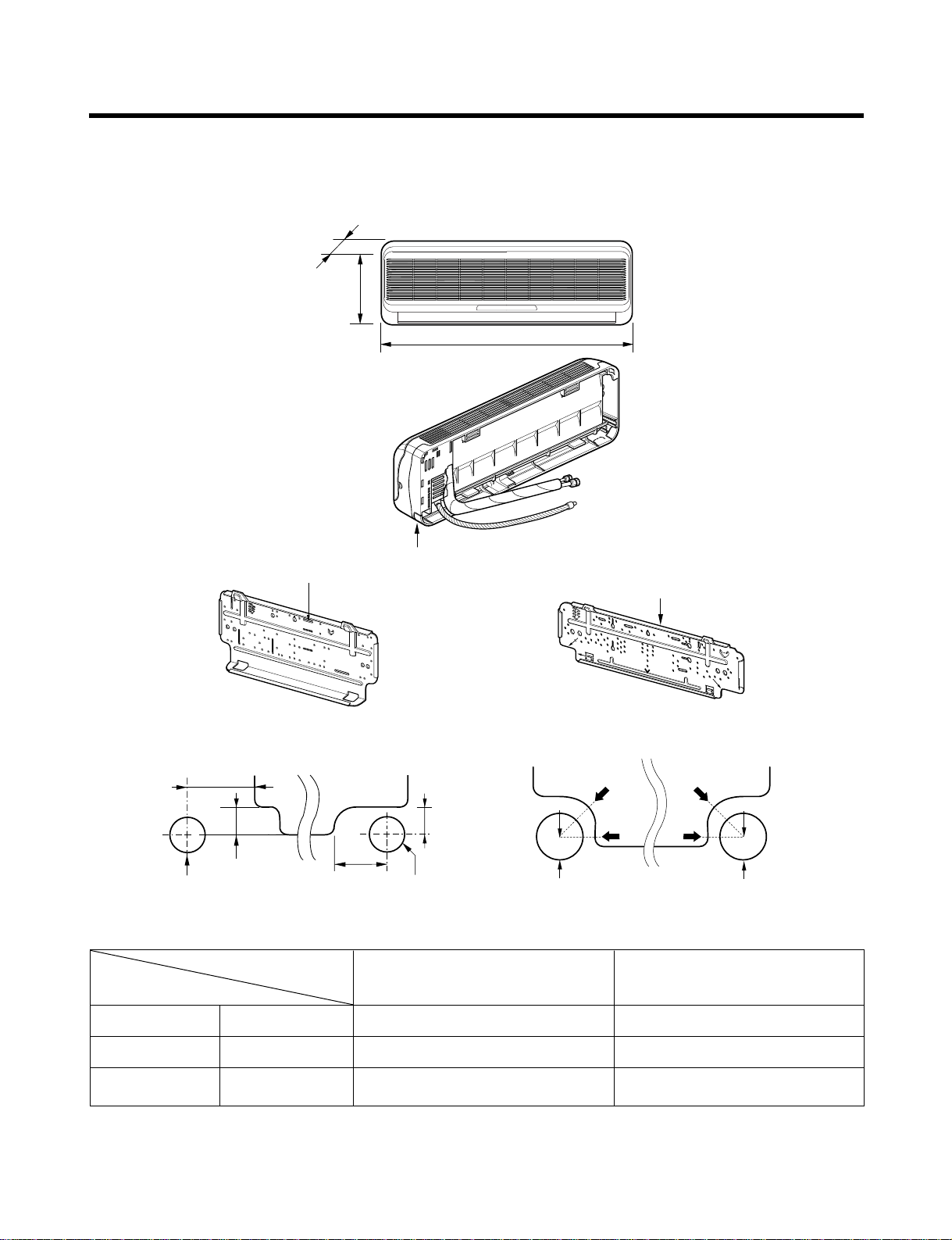
1. Indoor Unit
- 17 -
Dimensions
Installation plate
Installation plate
Right rear piping
Left rear piping
ø70mm
ø70mm
50mm
20mm
20mm
80mm
A
A
ø70mm
Center
Center
ø70mm
Left rear piping Right rear piping
A
A
D
H
W
Tubing hole cover
W mm 802 888
H mm 262 287
D mm 165 170
6K, 7K, 8K, 9K Btu Series
9K, 10K, 12K Btu Series
MODEL
DIM
( 6K, 7K, 8K, 9K )
( 6K, 7K, 8K, 9K )
( 9K, 10K, 12K )
( 9K, 10K, 12K )

- 18 -
W
L6L7 L8 L9
L4
H
D
L1
L2
L3
L5
L10
Gas side
3-way valve
Liquid side
2-way valve
L13L12L11
2. Outdoor Unit
2-1 LM-1460C2L/M, LM-1560C2L/M, LM-1460H2L/M, LM-1723C2L/M
W mm 801
H mm 555
D mm 262
L1 mm 339
L2 mm 300
L3 mm 37
L4 mm 543.6
L5 mm 11.4
L6 mm 591
L7 mm 105
L8 mm 105
L9 mm 72.5
L10 mm 74.5
L11 mm 79
LM-1460C2L/M, LM-1560C2L/M
LM-1460H2L/M, LM-1723C2L/M
MODEL
DIM

- 19 -
W
D
L1
L2
L9
L4
L3
H
L10
L10
L10
L8
Gas side
3-Way valve
Liquid side
2-Way valve
L7L5L6
2-2. LM-1963C2L/M, LM-2163C2L/M, LM-1963H2L/M, LM-2163H2L/M
W mm 870
H mm 655
D mm 320
L1 mm 370
L2 mm 25
L3 mm 630
L4 mm 25
L5 mm 546
L6 mm 160
L7 mm 160
L8 mm 64
L9 mm 76.5
L10 mm 50
LM-1963C2L/M, LM-2163C2L/M, LM-1963H2L/M, LM-2163H2L/M
MODEL
DIM

- 20 -
W
D
L1
L2
L9
L4
L3
H
L10
L10
L10
L8
Gas side
3-Way valve
Liquid side
2-Way valve
L7L5L6
2-3. LM-2064C3L/M, LM-2063H3L/M
LM-3063C3L/M, LM-3063H3L/M
W mm 870 870
H mm 655 800
D mm 320 320
L1 mm 370 370
L2 mm 25 25
L3 mm 630 775
L4 mm 25 25
L5 mm 546 546
L6 mm 160 160
L7 mm 160 160
L8 mm 64 64
L9 mm 76.5 76.5
L10 mm 50 50
LM-2064C3L/M, LM-2063H3L/M
LM-3063C3L/M, LM-3063H3L/M
MODEL
DIM

- 21 -
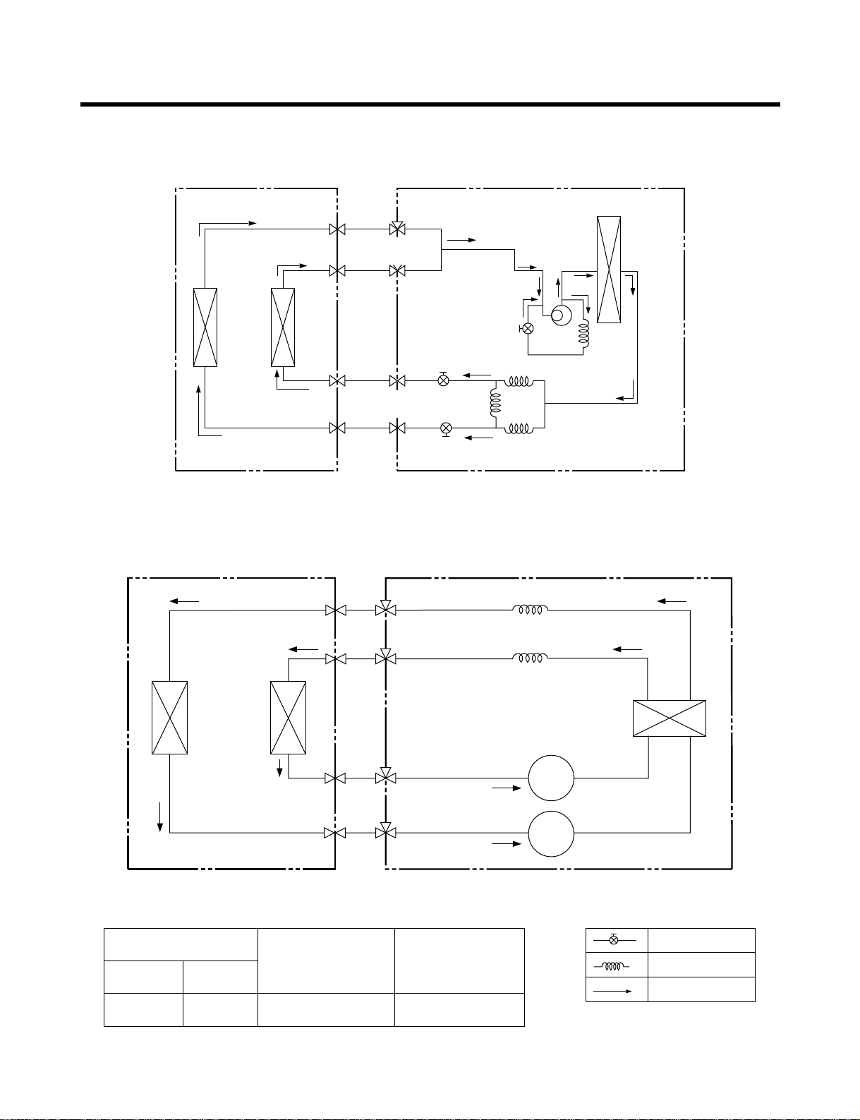
Refrigeration Cycle Diagram
Pipe Size (Diameter : inch)
Max.
piping length
(m)
Max.
piping elevation
(m)
Gas Liquid
3/8" 1/4" 10~15 5~7
ex)
Solenoid Valve
Capillary
Cooling & Deice
Heating
Indoor Unit Outdoor Unit
Heat
Exchanger
A-Unit
B-Unit
Heat
Exchanger
2- WAY
Valve
3- WAY
Valve
COMPRESSOR
Indoor Unit Outdoor Unit
Heat
Exchanger
4- WAY
Valve-B
Comp
A-Unit
B-Unit
Heat
Exchanger
2- WAY
Valve
3- WAY
Valve
1. LM-1460C2L/M, LM-1560C2L/M (Cooling only models)
2. LM-1460H2L/M (Cooling & Heating modes)
- 22 -
3. LM-1723C2L/M(Cooling only modes)
4. LM-1963C2L/M, LM-2163C2L/M(Cooling only models)
Pipe Size (Diameter : inch)
Max.
piping length
(m)
Max.
piping elevation
(m)
Gas Liquid
3/8" 1/4" 10~15 5~7
ex)
Solenoid Valve
Capillary
Cooling & Deice
Indoor Unit Outdoor Unit
Heat
Exchanger
A-Unit
B-Unit
Heat
Exchanger
2- WAY
Valve
3- WAY
Valve
COMP
A-UNIT B-UNIT
CAPILLARY TUBE
LIQUID SIDE
2-WAY VALVE
GAS SIDE
3-WAY VALVE
HEAT
EXCHANGER
(EVAPORATOR)
HEAT
EXCHANGER
(CONDENSER)
COMPRESSOR
B
COMPRESSOR
A

- 23 -
5. LM-1963H2L/M, LM-2163H2L/M(Cooling & Heating models)
6. LM-2064C3L/M, LM-3063C3L/M(Cooling only models)
Pipe Size (Diameter : inch)
Max.
piping length
(m)
Max.
piping elevation
(m)
Gas Liquid
3/8"(1/2") 1/4" 10~15 5~7
ex)
Solenoid Valve
Capillary
Cooling & Deice
Heating
HEAT
EXCHANGER
COOLING
HEATING
DEICE
HEAT
EXCHANGER
CAPILLARY TUBE
COMPRESSOR-B
COMPRESSOR-A
CAPILLARY TUBE
2-WAY
VALVE
4-WAY
VALVE
B-UNITA-UNIT
3-WAY
VALVE
4-WAY
VALVE
Indoor Unit Outdoor Unit
Indoor Unit Outdoor Unit
Heat
Exchanger
A-Unit
Heat
Exchanger
Comp-A
Comp-B
B-Unit
C-Unit
Heat
Exchanger
2- WAY
Valve
3- WAY
Valve
2- WAY
Valve
3- WAY
Valve

- 24 -
7. LM-2063H3L/M, LM-3063H3L/M(Cooling & Heating models)
Pipe Size (Diameter : inch)
Max.
piping length
(m)
Max.
piping elevation
(m)
Gas Liquid
3/8"(1/2") 1/4" 10~15 5~7
ex)
Solenoid Valve
Capillary
Cooling & Deice
Heating
Indoor Unit Outdoor Unit
Heat
Exchanger
A-Unit
Heat
Exchanger
Comp-A
B-Unit
C-Unit
Heat
Exchanger
2- WAY
Valve
3- WAY
Valve
2- WAY
Valve
3- WAY
Valve
Comp-B

3854A20023C
INDOOR WIRING DIAGRAM
CN-DISP1
CN-U/D
FUSE
AC250V/T2A
CN-TH1
SSR
SH-CAPA.
BR
YL
OR
BK
ZNR
THERMISTOR
FORCED
OPERATION
AUTO
RESTART
REMOTE
CONTROL
STEP
MOTOR
MOTOR
MAIN PCB
ASM
DISPLAY PCB ASM
TO OUTDOOR UNIT
PILLAR
TERMINAL
BR
BL
YL
GN/YL
1(L) 2(N
)
3
RY-COMP.
4
3
CN-POWER CN-MOTOR
3854A20023D
INDOOR WIRING DIAGRAM
CN-DISP1
CN-U/D
FUSE
AC250V/T2A
CN-TH1
SSR
SH-CAPA.
BR
YL
OR
BK
CN-TAB1
ZNR
CN-MOTOR
THERMISTOR
FORCED
OPERATION
AUTO
RESTART
REMOTE
CONTROL
STEP
MOTOR
MOTOR
MAIN PCB
ASM
DISPLAY PCB ASM
TO OUTDOOR UNIT
PILLAR
TERMINAL
BR
BL
YL
GN/YL
1(L) 2(N
)
3
RY-COMP.
4
3
3854A20023B
INDOOR WIRING DIAGRAM
CN-DISP1
CN-U/D
FUSE
AC250V/T2A
CN-TH
SSR
SH-CAPA.
BR
YL
OR
BK
CN-POWER CN-FAN
ZNR
THERMISTOR
FORCED
OPERATION
AUTO
RESTART
REMOTE
CONTROL
STEP
MOTOR
MOTOR
MAIN PCB
ASM
DISPLAY PCB ASM
TO OUTDOOR UNIT
PILLAR
TERMINAL
BR
BL
YL
1(L) 2(N
)
3
- 25 -
Wiring Diagram(Indoor Unit)
1. LM-1460C2L/M, LM-1723C2L/M
LM-1963C2L/M, LM-2163C2L/M(9K)
LM-1560C2L/M
2. LM-2163C3L/M(12K)
3. LM-1460H2L/M, LM-1963H2L/M, LM-2163H2L/M, LM-2063H3L/M,
LM-3063H3L/M, LM-3063C3L/M, LM-2064C3L/M

1(L)2(N)1(L)2(N)3(A)3(B
)
THERMISTOR
OUTDOOR WIRING DIAGRAM
MOTOR COMP
C S SC
R
R
CN-TH
5(B)
BL
YL
BL BL
RD
CAPA.
F C H
BR
BK
RD
BR
O.L.P
BR
CN-FAN
YL
BL BL
WH
MAIN A unit
3854A30076F
B unit
BK
BK
T/BLOCK 1
T/BLOCK 2
TERMINAL
BLOCK(6P)
BL
WH
BK
BK
A
S/VBS/V
CN-S.V
RY-S.V2
RY-S.V1
7(A)
CN-TRANS
RY-HI
RY-COMP
CN-POWER
CN-COM
CN-COMP
FUSE(250V/3.15A)
MAIN P.C.B. ASM
1(L)2(N)1(L)2(N)3(A)3(B
)
THERMISTOR
OUTDOOR WIRING DIAGRAM
MOTOR COMP
C S SC
R
R
CN-TH
5(B)
BL
YL
BL BL
RD
CAPA.
F C H
BR
BK
RD
BR
O.L.P
BR
CN-FAN
YL
BL BL
RD BK
WH
3854A30076E
BK
BK
T/BLOCK 1
T/BLOCK 2
TERMINAL
BLOCK(6P)
BL RD
WH
BK
BK
A
S/VBS/V
R/V
CN-S.V
RY-2 (S/V B)
RY-3 (R/V)
RY-1 (S/V B)
7(A)
CN-TRANS
RY-HI
RY-COMP
CN-POWER
CN-COM
CN-COMP
FUSE(250V/3.15A)
MAIN P.C.B. ASM
MAIN A unit B unit
BK
RD
R
C
O.L.P
BR
RD
WH
A-UNIT
TO INDOOR UNIT
OUTDOOR WIRING DIAGRAM 3854A20023A
B-UNIT MAIN POWER
1(L) 2(N) 3 3 2(N) 1(L) 1(L) 2(N)
BK RD BL
BL
BL
RD
POWER
RELAY
OR
OR
MOTOR
YLBK
O.L.P
T/B 3
T/B 4
T/B 1
T/B 2
C
R
F C H
S WH
BL
BR
BK
COMP
"B"
CAPACITOR
NO
NC
C
3
6
1
7
8
BK
WH
BK
BK
TERMINAL
BLOCK
GN/YL
GN/YL
S
COMP
"A"
YL
CAPACITOR
1(L)2(N)1(L)2(N)3(A)3(B
)
THERMISTOR
OUTDOOR WIRING DIAGRAM
MOTOR COMP
C S SC
R
R
CN-TH
5(B)
BL
YL
BL BLBR
RD
CAPA.
F C H
BK
RD
BR
CN-FAN
YL
BL BL BL
WH
3854A30076D
BK
BK
T/BLOCK 1
T/BLOCK 2
TERMINAL
BLOCK(6P)
BL BK
WH
BK
BK
A
S/VBS/VBPS/V
CN-S.V
CN-BYPASS
RY-S.V1
RY-S.V2
RY-BP1
7(A)
CN-TRANS
RY-HI
RY-COMP
CN-POWER
CN-COM
CN-COMP
FUSE(250V/3.15A)
MAIN P.C.B. ASM
MAIN A unit B unit
- 26 -
Wiring Diagram(Outdoor Unit)
1. LM-1460C2L/M, LM-1560C2L/M 2. LM-1460H2L/M
3. LM-1723C2L/M 4. LM-1963C2L/M

OUTDOOR WIRING DIAGRAM
3854AP3911C
MAIN PCB ASSY
TO INDOOR UNIT
A-UNIT B-UNIT
MAIN
POWER
TERMINAL
BLOCK
CN-TRANS
BK BK
BR
BL
BL YL
BK BK
BK
BK
BK
BK
OR
H C F
YL
BK
BK
"A"
COMP
BLBKRD
RD
S R
C
OLP
C
R
BR
BK
YL
S
BK
BK
T/B2
T/B1
T/B3
GN/YL
MOTOR
BK
7
4 33 11 3 2 1
5 3 1 3 1
BK
WH
WH BK
GN/YL
GN/YL
WH
CN-COM
CN-TH1 CN-TH2
CN-POWER
CN-SV
RY9
RY3
RY2
RY1
RY10
CN-FANCN-COMP
CAPA.
CAPA.
FUSE T3.15A
THERMISTOR
THERMISTOR
TRANSFORMER
OLP
"B"
COMP
1(L) 1(L)2(N) 1(L) 2(N)2(N)
3 3
A 4-WAY
B 4-WAY
OPTION
MOTOR
B/P2 S.V
OUTDOOR WIRING DIAGRAM
3854A20023E
MAIN PCB ASSY
TO INDOOR UNIT
A-UNIT B-UNIT C-UNIT
MAIN
POWER
TERMINAL
BLOCK
CN-TRANS
BK
BR
BL
BK BK
BK
BK
"A"
COMP
BL
BK
BR WH RD BL YL
BL BL BL BK BK
BL BL BL BK BK
RD
RD
S R
C
OLP
C
R
BR
BK
YL
S
BK
BK
YL
OR
OPTION
BK(Hi)
BK
T/B2 T/B3
OPTION
T/B1
T/B4
7
1 3
1 3
5 3 1 3 1
BK
WH
BK
WH
RD WH BK
GN/YL
CN-COM
CN-TH1 CN-TH2
CN-POWER
RY8
RY9
RY3
RY2
RY1
CN-FAN CN-BYPASSCN-COMP
CAPA.
CAPA.
FUSE T3.15A
THERMISTOR
THERMISTOR
TRANSFORMER
OLP
OPTION
OPTION
2 1
RY10
RY7
RY5
RY4
"B"
COMP
1(L) 1(L)2(N) 1(L) 2(N)2(N)
3 3 3
H C F
B-S.V
C-S.V
A 4-WAY
B 4-WAY
4 3 2 1
CN-SV
BK
T/B1BK
CAPA.
CAPA.
RY1
RY2
RY3
RY7
RY8
CN-TH2
CN-SV
CN-TH1
FCH
3 131
BK
BK
BL
BK
T/B2
BL
BL BL
WH
BR
BL
RD WH
GN/YL
TERMINAL
BLOCK
WH
BK
WH
BK
BK
BK
RD
BK
BK
BR
YL
YL
GN/YL
OR
RD
SSR
R
C
C
BK
RD BL
CN
-
FAN
CN-COMP
BK
"B"
COMP
"A"
COMP
MOTOR
34
7 5 3 1 13
2 1
FUSE T3.15A
CN-POWERCN-COM
MAIN PCB ASSY
CN-TRANS
TRANS-
FORMER
B S.V
C S.V
1(L) 2(N) 3 3 2(N) 1(L) 3 1(L) 2(N)
A-UNIT B-UNIT
TO INDOOR UNIT
C-UNIT MAIN
POWER
OUTDOOR WIRING DIAGRAM
3854A30076G
T/B3
OLPOLP
BK
T/B1BK
CAPA.
CAPA.
OLP
RY1
RY2
RY3
RY7
RY8
CN-TH2
CN-SV
CN-TH1
FCH
1 3 131
BK
BK
BL
BK
T/B2
BL
BL BL
WH
BR
BL
RD WH
GN/YL
TERMINAL
BLOCK
WH
BK
WH
BK
BK
BK
RD
BK
BK
BR
YL
YL
OR
RD
SSR
R
C
C
BK
BL RD
CN-FAN
CN-COMP
BK
"A"
COMP
"B"
COMP
MOTOR
34
7 5 3 1
2 1
FUSE T3.15A
CN-POWERCN-COM
MAIN PCB ASSY
CN-TRANS
TRANSFORMER
B S.V
C S.V
1(L) 2(N) 3 3 2(N) 1(L) 3 1(L) 2(N)
A-UNIT B-UNIT
TO INDOOR UNIT
C-UNIT MAIN
POWER
OUTDOOR WIRING DIAGRAM
3854A20023F
T/B3
- 27 -
5. LM-1963H2L/M, LM-2163H2L/M 6. LM-2063H3L/M, LM-3063H3L/M
7. LM-2064C3L/M 8. LM-3063C3L/M

Operation Details
1. MAIN UNIT FUNCTION
• DISPLAY
1) C/O Model
Operation Indicator
• On while in appliance operation, off while in appliance pause
• Flashing while in disconnection or short in Thermistor (3 sec off / 0.5 sec on)
Sleep Timer Indicator
• On while in sleep timer mode, off when sleep timer cancel or appliance operation pause
Timer Indicator
• On while in timer mode (on/off), off when timer mode is completed or canceled.
Comp. Running Incidator
• While in appliance operation, on while in outdoor unit compressor running, off while in compressor off
2) H/P Model
Operation Indicator
• On while in appliance operation, off while in appliance pause
• Flashing while in disconnection or short in Thermistor (3 sec off / 0.5 sec on)
Sleep Timer Indicator
• On while in sleep timer mode, off when sleep timer cancel or appliance operation pause
Timer Indicator
• On while in timer mode (on/off), off when timer mode is completed or canceled
Defrost Indicator
• Off except when hot start during heating mode operation or while in defrost control
■ Cooling Mode Operation
• When the intake air temperature reaches 0.5°C below the setting temp, the compressor and the outdoor fan
stop.
• When it reaches 0.5°C above the setting temp, they start to operate again.
Compressor ON Temp ➲ Setting Temp+0.5°C
Compressor OFF Temp ➲ Setting Temp-0.5°C
• While in compressor running, operating with the airflow speed set by the remote control. While in compressor
not running, operating with the low airflow speed regardless of the setting.
■ Healthy Dehumidification Mode
• When the dehumidification operation input by the remote control is received, the intake air temperature is
detected and the setting temp is automatically set according to the intake air temperature.
26°C ≤ Intake Air Temp ➲ 25°C
24°C ≤ Intake Intake Air Temp<26°C ➲ Intake Air Temp-1°C
18°C ≤ Intake Intake Air Temp<24°C ➲ Intake Air Temp-0.5°C
Intake Air Temp<18°C ➲ 18°C
-28-

• While in compressor off, the indoor fan repeats low airflow speed and pause.
• While the intake air temp is between compressor on temp. and compressor off temp., 10-min dehumidification operation and 4-min compressor off repeat.
Compressor ON Temp. ➲ Setting Temp+0.5°C
Compressor OFF Temp. ➲ Setting Temp-0.5°C
• In 10-min dehumidification operation, the indoor fan operates with the low airflow speed.
■ Heating Mode Operation(H/P model)
• When the intake air temp reaches +3°…above the setting temp, the compressor is turned off. When below
the setting temp, the compressor is turned on.
Compressor ON Temp. ➲ Setting Temp.
Compressor OFF Temp. ➲ Setting Temp.+3°C
• While in compressor on, the indoor fan is off when the indoor pipe temp. is below 20°C, when above 28°C , it
operates with the low or setting airflow speed. When the indoor pipe temp is between 20°C and 28°C, it operates with Super-Low(while in sleep mode, with the medium airflow speed).
• While in compressor off, the indoor fan is off when the indoor pipe temp is below 33°C, when above 35°C , it
operates with the low airflow speed.
• If overloaded while in heating mode operation, in order to prevent the compressor from OLP operation, the
outdoor fan is turned on/off according to the indoor pipe temp.
• While in defrost control, both of the indoor and outdoor fans are turned off.
■ Defrost Control(H/P model)
• Defrost operation is controlled by timer and sensing temperature of outdoor pipe.
• The first defrost starts only when the outdoor pipe temperature falls below -6°C after 60 minutes passed from
starting of heating operation and more than 10 minutes operation of compressor.
• Defrost ends after 12 minutes passed from starting of defrost operation or after the outdoor fan operates within max. 2 minutes 30 seconds when the outdoor pipe temperature rises over 12°C even it before 12 minutes.
• The second defrost starts only when the outdoor pipe temperature falls below -6°C after 60 minutes passed
from ending of the first defrost and more than 10 minutes operation of compressor.
■ Cooling overload(except : LM-1963C2L/M, LM-1723C2L/M, LM-2163C2L/M, LM-1460C2L/M)
• Control indoor fan by sensing outdoor pipe temperature.
• One step down from setting fan speed if pipe temperature is oven 50°C and if below 45°C, operate on setting
temperature.
■ Heating overload(H/P models)
• Outdoor fan ON/OFF by sensing outdoor pipe temperature.
• Outdoor fan is OFF if pipe temperature is over 6.5°C and outdoor fan is ON if pipe temperature is below 0°C.
• Outdoor fan is off if any one part is heating overload condition.
-29-

-30-
■ Fuzzy Operation (C/O Model)
• According to the temperature set by Fuzzy rule, when the intake air temp is 0.5°C or more below the setting
temp, the compressor is turned off. When 0.5°C or more above the setting temp, the compressor is turned on.
Compressor ON Temp ➲ Setting Temp + 0.5°C
Compressor OFF Temp ➲ Setting Temp + 0.5°C
• At the beginning of Fuzzy mode operation, the setting temperature is automatically selected according to the
intake air temp at that time.
26°C ≤ Intake Air Temp ➲ 25°C
24°C ≤ Intake Air Temp < 26°C ➲ Intake Air Temp + 1°C
22°C ≤ Intake Air Temp < 24°C ➲ Intake Air Temp + 0.5°C
18°C ≤ Intake Air Temp < 22°C ➲ Intake Air Temp
Intake Air Temp<18°C ➲ 18°C
• When the Fuzzy key (Temperature Control key) is input after the initial setting temperature is selected, the
Fuzzy key value and the intake air temperature at that time are compared to select the setting temperature
automatically according to the Fuzzy rule.
• While in Fuzzy operation, the airflow speed of the indoor fan is automatically selected according to the
temperature.
■ Fuzzy Operation (H/P Model)
• When any of operation mode is not selected like the moment of the power on or when 3 hrs has passed since
the operation off, the operation mode is selected.
• When determining the operation mode, the compressor, the outdoor fan, and the 4 way valve are off and only
the indoor fan is operated for 15 seconds. Then an operation mode is selected according to the intake air
temp at that moment as follows.
24°C ≤ Inatake Air Temp ➲ Fuzzy Operation for Cooling
21°C ≤ Inatake Air Temp<24°C ➲ Fuzzy Operation for Dehumidification
Inatake Air Temp<21°C ➲ Fuzzy Operation for Heating
• If any of the operation modes among cooling / dehumidification / heating mode operations is carried out for 10
sec or longer before Fuzzy operation, the mode before Fuzzy operation is operated.
1) Fuzzy Operation for Cooling
• According to the setting temperature selected by Fuzzy rule, when the intake air temp is 0.5°C or more below
the setting temp, the compressor is turned off. When 0.5°C or more above the setting temp, the compressor
is turned on.
Compressor ON Temp ➲ Setting Temp +0.5°C
Compressor OFF Temp ➲ Setting Temp + 0.5°C
• At the beginning of Fuzzy mode operation, the setting temperature is automatically selected according to the
intake air temp at that time.
26°C≤ Intake Air Temp ➲ 25°C
24°C≤ Intake Air Temp<26°C ➲ Intake Air Temp + 1°C
22°C≤ Intake Air Temp<24°C ➲ Intake Air Temp + 0.5°C
18°C≤ Intake Air Temp<22°C ➲ Intake Air Temp
Intake Air Temp<18°C ➲ 18°C
• When the Fuzzy key (Temperature Control key) is input after the initial setting temperature is selected, the
Fuzzy key value and the intake air temperature at that time are compared to select the setting temperature
automatically according to the Fuzzy rule.
• While in Fuzzy operation, the airflow speed of the indoor fan is automatically selected according to the temperature.
 Loading...