


Dynamic Controller
Owner’s Manual
MODEL : LKD1000
Before installing and using the product, please read this owner's
manual carefully and retain for future reference.
LKD1000.AA5TALG_ENG_V2_MFL6203471 1 2009.2.19 3:19:32 PM
2
CAUTION
RISK OF ELECTRIC SHOCK
DO NOT OPEN
CAUTION: TO REDUCE THE RISK OF ELECTRIC SHOCK
DO NOT REMOVE COVER (OR BACK)
NO USER-SERVICEABLE PARTS INSIDE
REFER SERVICING TO QUALIFIED SERVICE
PERSONNEL.
This lightning flash with arrowhead symbol
within an equilateral triangle is intended to
alert the user to the presence of uninsulated dangerous voltage within the product’s
enclosure that may be of sufficient magnitude to constitute a risk of electric shock to
persons.
The exclamation point within an equilateral
triangle is intended to alert the user to the
presence of important operating and maintenance (servicing) instructions in the literature accompanying the product.
FCC WARNING: This equipment may generate or
use radio frequency energy. Changes or modifications to this equipment may cause harmful interference unless the modifications are expressly
approved in the instruction manual. The user could
lose the authority to operate this equipment if an
unauthorized change or modification is made.
REGULATORY INFORMATION: FCC Part 15
This equipment has been tested and found to comply
with the limits for a Class A digital device, pursuant to
Part 15 of the FCC Rules. These limits are designed
to provide reasonable protection against harmful
interference when the equipment is operated in a
commercial environment.
This equipment generates, uses, and can radiate
radio frequency energy and, if not installed and used
in accordance with the instruction manual, may cause
harmful interference to radio communications.
Operation of this equipment in a residential area is
likely to cause harmful interference in which case the
user will be required to correct the interference at his
own expense.
• A suitable conduit entries, knock-outs or glands
shall be provided in the cable entries of this product in the end user.
• Caution: Danger of explosion if battery is incor
rectly replaced. Replaced only with the same or
equivalent type recommended by the manufacturer. Dispose of used batteries according to the
manufacturer’s instructions.
• Holes in metal, through which insulated wires
pass, shall have smooth well rounded surfaces or
shall be provided with brushings.
Warning: Do not install this equipment in a confined
space such as a bookcase or similar unit.
Warning: Wiring methods shall be in accordance
with the National Electric Code, ANSI/NFPA 70.
Warning: This is a class A product. In a domestic
environment this product may cause radio interference in which case the user may be required to take
adequate measures.
Warning: To reduce a risk of fire or electric shock, do
not expose this product to rain or moisture.
Caution: This installation should be made by a qualified service person and should conform to all local
codes.
Caution: To avoid electrical shock, do not open the
cabinet. Refer servicing to qualified personnel only.
Caution: The apparatus shall not be exposed to
water (dripping or splashing) and no objects filled
with liquids, such as vases, shall be placed on the
apparatus.
LKD1000.AA5TALG_ENG_V2_MFL6203472 2 2009.2.19 3:19:36 PM
3
Disposal of your old appliance
1. When this crossed-out wheeled bin symbol
is attached to a product it means the product is covered by the European Directive
2002/96/EC.
2. All electrical and electronic products
should be disposed of separately from the
municipal waste stream via designated
collection facilities appointed by the government or the local authorities.
3. The correct disposal of your old appliance
will help prevent potential negative consequences for the environment and human
health.
4. For more detailed information about disposal of your old appliance, please contact
your city office, waste disposal service or
the shop where you purchased the product.
This product is manufactured to comply with EMC Directive 2004/108/EC and
Low Voltage Directive 2006/95/EC.
European representative :
LG Electronics Service Europe B.V.
Veluwezoom 15, 1327 AE Almere, The
Netherlands (Tel : +31-036-547-8940)
IMPORTANT SAFETY INSTRUCTIONS
1. Read these instructions.
2. Keep these instructions.
3. Heed all warnings.
4. Follow all instructions.
5. Do not use this apparatus near water.
6. Clean only with dry cloth.
7. Do not block any ventilation openings. Install in
accordance with the manufacturer’s instructions.
8. Do not install near any heat sources such as
radiators, heat registers, stoves, or other apparatus
(including amplifiers) that produce heat.
9. Do not defeat the safety purpose of the polarized
or grounding-type plug. A polarized plug has two
blades with one wider than the other. A grounding
type plug has two blades and a third grounding
prong. The wide blade or the third prong are provided for your safety. If the provided plug does not
fit into your outlet, consult an electrician for replacement of the obsolete outlet.
10. Protect the power cord from being walked on or
pinched particularly at plugs, convenience receptacles, and the point where they exit from the apparatus.
11. Only use attachments/accessories specified by the
manufacturer.
12. Use only the cart, stand, tripod, bracket, or table
specified by the manufacturer, or sold with apparatus. When a cart is used, use caution when moving
the cart/apparatus combination to avoid injury from
tip-over.
13. Unplug this apparatus during lightning storms or
when unused for long periods of time.
14. Refer all servicing to qualified service personnel.
Servicing is required when the apparatus has been
damaged in any way, such as power- supply cord or
plug is damaged, liquid has been spilled or objects
have fallen into the apparatus, the apparatus has
been exposed to rain or moisture, does not operate
normally, or has been dropped.
LKD1000.AA5TALG_ENG_V2_MFL6203473 3 2009.2.19 3:19:38 PM

4
CONTENTS
INTRODUCTION .................................. 5
About LKD1000 Controller .................................5
Features ...............................................................5
Identification of the Controller .........................6
HOOKUP AND SETTINGS .................. 8
Basic Connection Overview ..............................8
RS-485 Connection .............................................9
Connecting the LG DVR .....................................9
Connecting the PTZ Camera ...........................10
Connecting the multiple LKD1000 controller 10
System Operation .............................................11
LKD1000 SETUP MENU ....................................11
Key Functions on the Setup menu ...............11
Change Password .........................................12
About DVR ....................................................12
About Camera ...............................................13
Change ID Setting .........................................13
Auto Lock Setting .........................................13
Factory Reset ................................................14
About LKD1000 .............................................14
OPERATION ...................................... 14
Operation the LG DVR ......................................14
Operation the connected camera via the
DVR ...............................................................16
Operation of the camera connected to
the LKD1000 controller directly .................16
Camera Control Menu ......................................17
Camera Control menu overview ...................17
Preset Settings ..............................................17
Auto Pan Setup and Activation .....................23
Pattern Setup and Activation ........................24
Privacy Setup ................................................25
Communication Settings ...............................26
Camera setup ...............................................29
REFERENCE ....................................32
Camera Control Function ................................32
Pan/Tilt Control .............................................32
Lens Control ..................................................32
Protocol Function Table ..................................33
Specifications ...................................................34
LKD1000.AA5TALG_ENG_V2_MFL6203474 4 2009.2.19 3:19:39 PM

5
INTRODUCTION
About LKD1000 Controller
This controller is the brand of Camera and DVR Controlling Keyboard of LG in a surveillance system. You can
operate this system very easily and conveniently because of design structure based on biotechnology and
various functions for users. In addition, the controller can control using the functions of the LG Camera and LG
DVR system.
The description functions used in this manual are based on LG Multix protocol.
The description functions may differ from your protocol.
Features
The Dynamic Controller offers the following functions:
x User-friendly Graphical User Interface.
x Compatible with LG Dome Cameras, Zoom Cameras and LG DVRs.
x Joystick Control for PTZ Functions.
x Program Preset Position and Pattern Control (Memorize continuous series of Zoom In/Out, Pan/Tilt).
x Control Privacy Zone Masking of the camera.
x Easy Firmware Upgrade
(Please contact authorized service center or where you purchased to upgrade the firmware.)
x Ergonomic Design.
x Directly Control the camera connected to LG DVR by using BY-PASS function of LKD1000 controller.
x Connect maximum 16 controller by using cascade (Master 1, Slave 15)
x Support the use of multiple controllers by cascading.
Note:
The Dynamic Controller is not provided with functions to control the audio signal. Audio communication is not
possible, regardless of whether audio boards are installed in the receiver.
LKD1000.AA5TALG_ENG_V2_MFL6203475 5 2009.2.19 3:19:39 PM
6
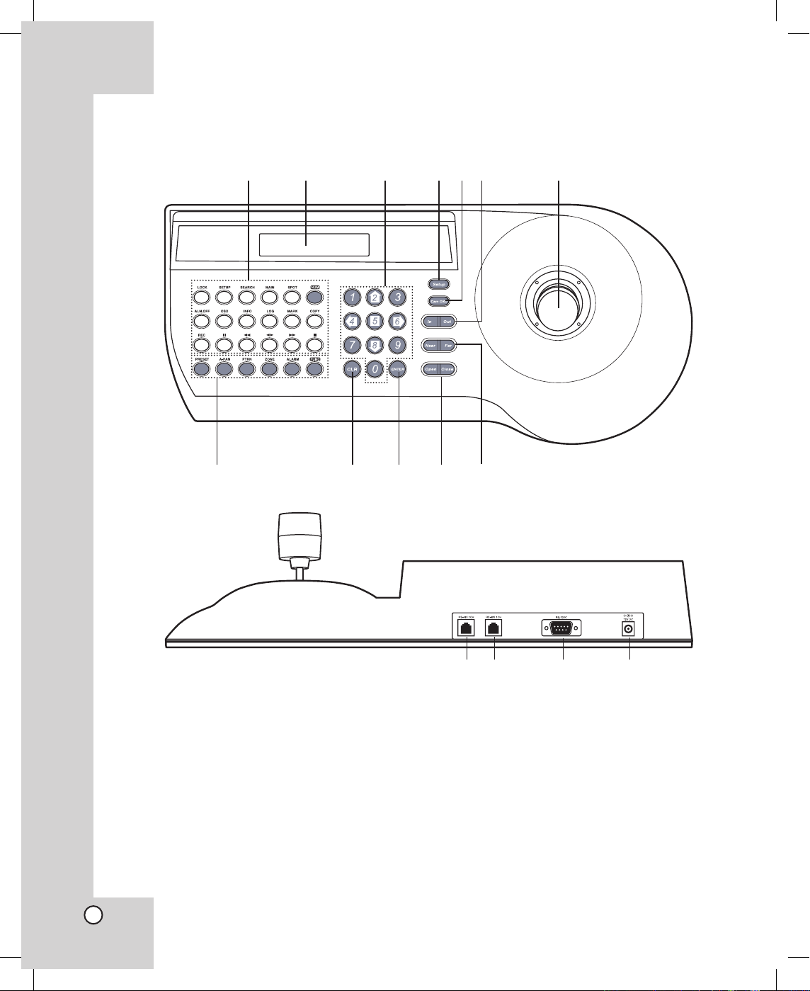
Identification of the Controller
mn o p
a b c def g
h i j k l
1 LG DVR Control Buttons
For details, see page 15.
2 Display Window
Displays function menus, numeric input, and
system status.
3 Numeric (0-9) and Arrow (left/right/up/down)
Buttons
Selects an option in the menu.
These buttons are used for numeric input of preset numbers or for executing each parameter on
the Controller’s menu.
4Setup Button
Opens controller’s main Setup menu in the display window.
5 Cam OSD Button
Opens or closes the Camera’s Setup menu on
the screen.
6 In/Out Buttons
These buttons are used to zoom the camera
image In (TELE) and Out (WIDE).
LKD1000.AA5TALG_ENG_V2_MFL6203476 6 2009.2.19 3:19:43 PM

7 Joystick Controller
This joystick manually operates the Pan/Tilt Head
and turning the joystick head to the left or right
will zoom or widen the image. (The zooming level
will go up or down.)
8 PTZ Camera Control Buttons
• PRESET Button
For details, see pages 17-23.
• A-PAN (Auto-Pan) Button
For details, see pages 23-24.
• PTRN (Pattern) Button
For details, see pages 24-25.
• ALARM Button
For details, see pages 22-23.
• FUNC Button
- In the LKD1000 setup menu:
> FUNC + Number 0: You can adjust the
brightness of the display window (4:
Decrease, 6: Increase).
- In the camera setup menu:
> FUNC + Number 1: If you use LG
Multix Protocol, you can set the parking
time to use the Auto Return function.
If you stop the preset tour, the preset
tour will automatically restarted after
the selected park time passes.
> FUNC + Number 6: If you use LG
Multix Protocol, press the button to
select the Focus mode (Auto, Manual
or PushAuto).
> FUNC + Number 9: If you use LG
Multix, LG Multix E or LG Zoom
Protocol, press the button to activate
auto focus. For using this function,
the camera's focus mode is set to one
push auto focus mode.
- FUNC + Number 2,3,5,7,8: These buttons
are not assigned.
9 CLR (CLEAR) Button
This button is used to return to the previous
menu or mode. Clears the parameter entered by
numeric buttons.
0 ENTER Button
This button is used to execute the currently
highlighted setting in the Setup menu.
qa Open/Close Buttons
The lens Iris is adjusted by pressing the Open or
Close button.
qs Near/Far Buttons
These buttons are used to adjust the lens focus
of cameras equipped with the specified lens.
qd RS-485 Data Ports (CH 2)
This port is used to connect the other LKD
1000 controller. If you want to use the multiple
LKD1000 controller, connect the RS-485 1CH of
the other LKD1000 controller to this port using the
RS-485 cable.
qf RS-485 Data Ports (CH 1)
This port is used to exchange control data
through the connected camera and/or DVR via
the RS-485 cable or by connecting the master (or
the other) controller.
qg RS-232C Port
This port is used only for authorized service purposes.
qh DC 12V Input Jack (12V DC)
Connect a DC 12V Certified/Listed, class 2 power
supply only to the DC input terminal on the back
of the controller.
7
LKD1000.AA5TALG_ENG_V2_MFL6203477 7 2009.2.19 3:19:43 PM
8
HOOKUP AND SETTINGS
Precautions
• The connections should be made by qualified service personnel or system installers in accordance with all
local codes.
• DC 12V can be used.
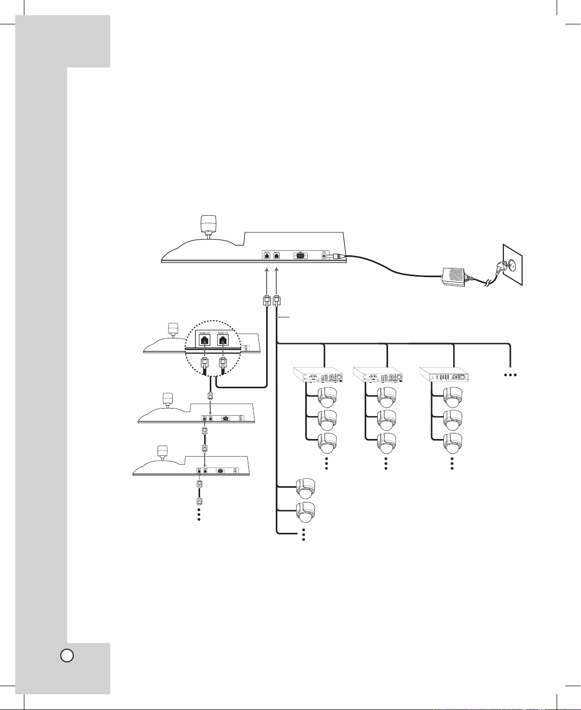
Basic Connection Overview
Notes:
• Please refer to the LG DVR and Camera manuals as necessary for additional connection information.
• Set the DVR ID and Camera ID differently for each DVR and Camera if many DVRs or cameras are con
-
nected to the LKD1000 controller.
DC 12V adaptor
(Not supplied).
LKD1000
Controller 1
(MASTER)
LKD1000
Controller 2
(SLAVER)
LKD1000
Controller 3
(SLAVER)
DVR 1
DVR 2
DVR 3
LKD1000
Controller 4
(SLAVER)
Camera 1
Camera 2
Up to 16 controllers.
Up to 256 cameras.
Up to
16 DVRs.
To RS-485 2CH
terminal.
To RS-485 1CH
terminal.
RJ11 Cable
(Supplied)
LKD1000.AA5TALG_ENG_V2_MFL6203478 8 2009.2.19 3:19:48 PM
9
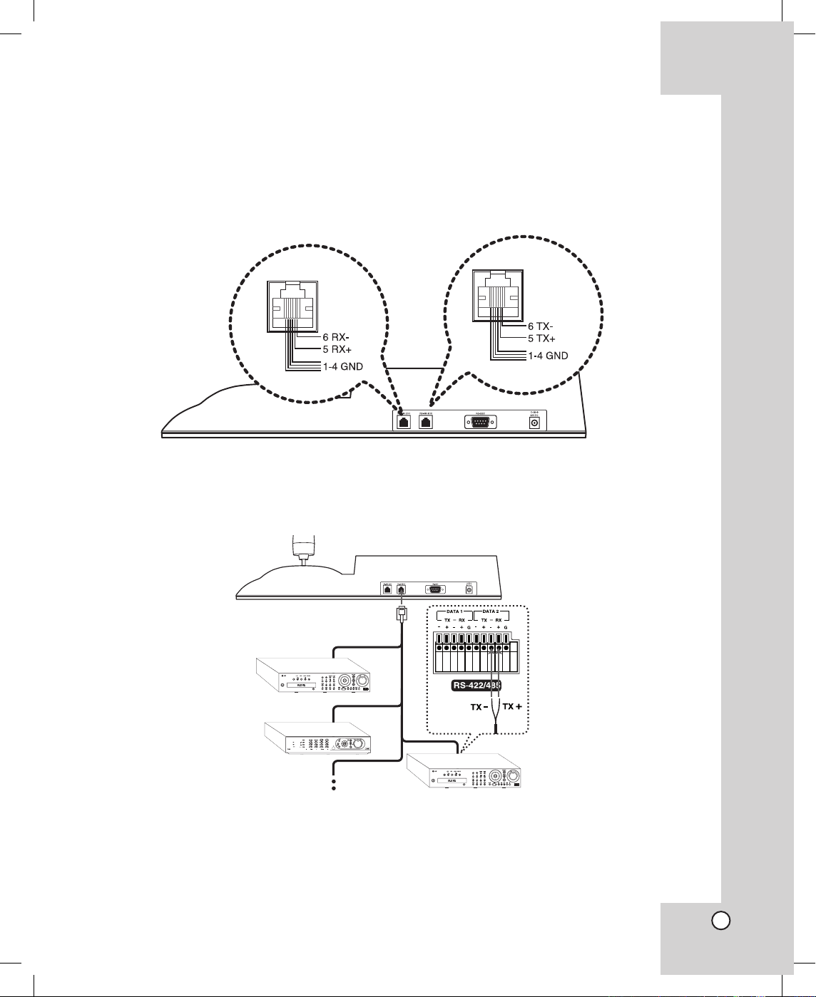
RS-485 Connection
Use this port to connect PTZ cameras or LG DVRs. Use the cable that is described below for RS-485 site
communication.
• Shielded, twisted pair cable
• Low impedance
• Wire gauge size is thicker than AWG #22 (0.33 mm2).
Connecting the LG DVR
You can connect up to 16 LG DVRs.
Connect the LG DVR to the RS-485 1CH terminal of the LKD1000 as shown below.
Notes:
• When connecting lines, connect the TX - of the LKD1000 controller to RX - (DATA2) of the LG DVR and TX
+ of the LKD1000 controller to RX + (DATA2) of the LG DVR correctly.
• Set the appropriate DVR system ID to operate via the LKD1000 Controller when using the multiple LG
DVR.
LKD1000.AA5TALG_ENG_V2_MFL6203479 9 2009.2.19 3:19:56 PM
10
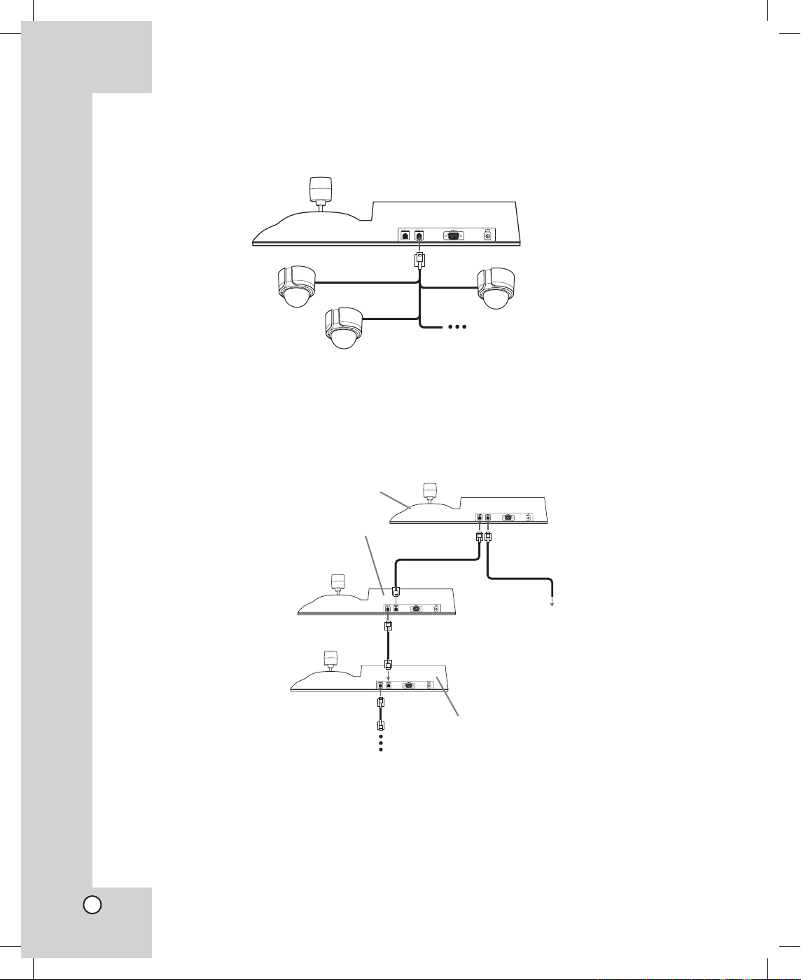
Connecting the PTZ Camera
You can connect up to 256 PTZ cameras. Connect the PTZ Camera to the RS-485 1CH terminal of the
LKD1000 as shown below.
Connecting the multiple LKD1000 controller
You can connect up to 16 LKD1000 controllers. If you use the multiple LKD1000 controller, you must set the
LKD1000 ID. Set to 1 for master controller and set to the other ID number (2~16) for the slave controller. The
Slave LKD1000 controller can control the DVRs or cameras through the master LKD1000 controller. When
connecting multiple LKD1000 controllers, connect as shown below.
To RS485 1CH
To RS485 2CH
Master LKD1000 Controller
First Slaver LKD1000 Controller
Second Slaver LKD1000 Controller
To LG DVRs or Cameras.
To RS485 1CH
To RS485 2CH
To RS485 1CH
To RS485 2CH
Note:
When you turning off the slave LKD1000 controller, you should disconnect the RS485 cable
between the master LKD1000 controller and slaver LKD1000 controller to prevent a malfunction of
the master LKD1000 controller.
LKD1000.AA5TALG_ENG_V2_MFL62034710 10 2009.2.19 3:20:0 PM
11
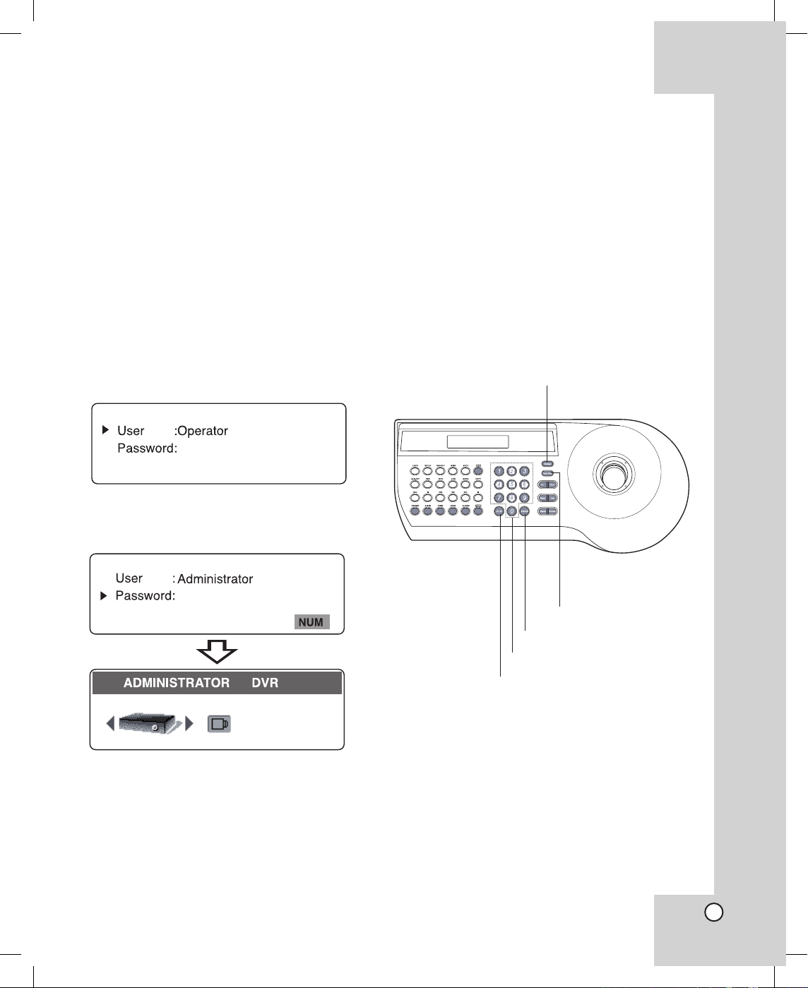
System Operation
Before starting operation, user authentication by the
password is required.
1. Check that the LG DVR or the camera, the moni
tor and peripherals are connected correctly and
securely.
2. Connect an DC 12V power source to the DC 12V
input terminal on the back of the controller.
3. Select a user by using the a
rrow (B/b) buttons,
then press the ENTER button.
Administrator: Unlimited operation of the unit.
Only administrator can access the LKD1000
setup menu and camera control menu.
Operator: Limited operation of the unit.
(Emulate the DVR keys and PTZ function are
available.)
4. Enter your password using the number buttons
then press ENTER. (Initial password is “000000”.)
The main menu will appear in the display window.
•
•
LKD1000 SETUP MENU
The setup menu has several submenus. All of these
main menus are further divided into submenus.
Press Setup to display the setup menu.
Key Functions on the Setup menu
• Setup button: To display the main menu.
• ENTER button: To execute or select modes and
parameters. To enter a submenu for the selected
item.
• CLR button: To return to the previous menu or to
delete input.
• Numeric buttons: Enter numbered value in a
menu.
•
Arrow buttons: Choose an item in the menu.
Camera OSD button
ENTER button
Number and Arrow buttons
CLR button
LKD1000 Setup button
LKD1000.AA5TALG_ENG_V2_MFL62034711 11 2009.2.19 3:20:3 PM

12
Change Password
The factory default of password is “000000”.
However, for security, you should change the password setting.
1. Select [Change Password] option then press
ENTER. The sub menu will appear.
2. Select the user to change the password and press
ENTER.
3. Enter current password using the number buttons then press ENTER. If you select [Change
Operator Password] option, enter the administrator's password.
In case of Administrator:•
In case of Operator:
4. Enter new password using the number buttons
then press ENTER. Enter the password again
to confirm, and press ENTER. The password is
stored.
Notes:
• You can enter the password from minimum 1-digit
number to 10-digit numbers.
• We recommend that you do not operate the con
-
troller during saving the password.
About DVR
Select [ABOUT DVR] option then press ENTER.
Shows DVR information.
•
LKD1000.AA5TALG_ENG_V2_MFL62034712 12 2009.2.19 3:20:9 PM

13
About Camera
Select [ABOUT CAMERA] option then press ENTER.
Shows camera information.
Change ID Setting
This LKD1000 controller has the controller ID. If you
use 2 controllers or more simultaneously, set the
controller ID for each controller.
1. Select [CHANGE ID] option then press ENTER.
The sub menu will appear.
CHANGE ID LKD1000
2. Enter the New LKD1000 ID for this controller
(1~16).
3. Press ENTER to save the settings.
Auto Lock Setting
The keys on the controller is locked when there is no
operation for selected duration on the [AUTO LOCK]
option. To release the Key Lock mode, you need to
enter the password.
• NONE: Auto Key Lock function is disable.
• After 1 min: The keys on the controller are locked
when there is no operation for 1 minute.
• After 3 min: The keys on the controller are locked
when there is no operation for 3 minutes.
• After 5 min: The keys on the controller are locked
when there is no operation for 5 minutes.
LKD1000.AA5TALG_ENG_V2_MFL62034713 13 2009.2.19 3:20:14 PM

14
Factory Reset
If you need to, you can reset the LKD1000 controller
to its original factory settings.
1. Select [FACTORY RESET] option then press
ENTER.
The sub menu will appear.
2. Enter the password and press ENTER.
3. Press ENTER to confirm it.
About LKD1000
Select [ABOUT LKD1000] option then press ENTER.
Shows model name and the current firmware version
of the controller.
OPERATION
Operation the LG DVR
You can control the connected LG DVR using the
LKD1000 controller.
1. Select DVR icon in the main menu and then
press ENTER. The DVR ID input menu will be
displayed.
2. Enter the connected DVR ID to control the DVR
and then press ENTER. The DVR key emulation
menu will be displayed.
3. Press ENTER to change the DVR control mode.
4. Use the DVR function keys to control the DVR.
LKD1000.AA5TALG_ENG_V2_MFL62034714 14 2009.2.19 3:20:21 PM

15
PRESET 000
PTZ
• LOCK
Displays the lock menu to change the user
type or disable the system operation.
• SETUP
Displays the setup menu or cancels operation
on the setup menus. Use to return to the previous menu or mode.
• SEARCH
Displays the search menu.
• MAIN
Display the MAIN menu to set the screen
mode to full, 4, 6, 8, 9 or 16 screens.
• SPOT
Enter SPOT mode to allow spot monitor control.
• NUM
Switches to number entering mode in a menu.
• ALM.OFF
Cancels alarm activation and returns the
system to the condition before the alarm was
activated.
• OSD
Accesses or removes the System Control Bar.
• INFO
Displays or removes system information.
• LOG
Displays or removes the System Log List.
• MARK
Sets the mark point for recording search.
• COPY
Copies the recording data to an external
device.
• REC
Starts or stops instant recording.
How to instant recording
(1) Press the REC.
(2) Press the NUM and then press the chan
-
nel button you want to record.
(3) Press ENTER to start recording. The
recording type indicator turns green on the
selected channel screen.
(4) If you stop the recording, repeat the step
(1)~(3) as the above.
• Playback control buttons
- X: Pauses playback.
- m: Search the recorded images in reverse
or skip the recorded images.
- bB: Playback or reverse playback of
recorded images.
- M: Forward search the recorded images
or skip the recorded images.
- x: Stops playback.
5. Press CLR to exit the DVR control mode.
LKD1000.AA5TALG_ENG_V2_MFL62034715 15 2009.2.19 3:20:23 PM

16
Operation the connected camera via the DVR
You can control the connected camera via the LG
DVR using the LKD1000 controller.
1. Follow steps 1-2 described in “Operation the LG
DVR”.
2. Use
the Arrow (B/b) buttons to select the camera and then press ENTER. The DVR/CAM ID
input menu will be displayed.
3. Enter the connected DVR/CAM ID to control the
camera connected to the DVR and then press
ENTER. The camera control menu will be displayed.
4. Use the Arrow (B/b) buttons to select the
"COMMUNICATION" option and press ENTER.
5. Set the desired options. (For more details, see
pages 26-28)
6. Use the camera control buttons and joystick to
control the camera.
Operation of the camera connected to the LKD1000 controller directly
You can control the camera connected to the
LKD1000 controller directly.
1. Select CAM (Camera) icon in the main menu and
then press ENTER. The camera ID input menu
will be displayed.
2. Enter the connected camera ID to control the
camera connected to the LKD1000 controller
directly and then press ENTER. The camera control menu will be displayed.
3. Use the Arrow (B/b) buttons to select the
"COMMUNICATION" option and press ENTER.
4. Set the desired options. (For more details, see
pages 26-28)
5. Use the camera control buttons and joystick to
control the camera.
LKD1000.AA5TALG_ENG_V2_MFL62034716 16 2009.2.19 3:20:26 PM

17
Camera Control Menu
The Camera Control menu has several submenus.
All of these main menus are divided into submenus.
Camera Control menu overview
Main Menu Sub Menu Page
PRESET
Set Preset 17
Go To Preset 18
Tour 18
Edit Group 19
Group Tour 20
Clear Preset 21
Clear All Preset 21
Set Alarm Input 22
Set Alarm Output 22
AUTO PANNING
Set Auto Panning 23
Run Auto Panning 24
PATTERN
Record Pattern 24
Play Pattern 25
PRIVACY ZONE
Set Zone Area 25
Display Zone Area 26
COMMUNICATION
Protocol 26
Baudrate 27
Parity Bit 27
Data Bit 28
Stop Bit 28
Sync Communication 28
CAMERA SETUP
Set Manual Focus
Speed
29
Go To PTZ Home
Position
29
Periodic PTZ Reset 30
PTZ Reset 30
Factory Reset 31
Notes:
The pictures used in the camera control menu are
based on DVR-camera menu.
Depending on protocol, some functions are not
activated. See page 33 for more details.
•
•
Preset Settings
Preset is the function to register camera monitoring
positions (pan, tilt and zoom positions) associated
with position numbers.
By entering the position numbers, you can set cameras to the preset positions.
Note:
To activate this function, you need to register the preset positions of camera.
To register preset positions
1. Select the [PRESET] icon and press ENTER.
The sub menu will appear.
2. Select [Set Preset] option then press ENTER.
The sub menu will appear.
3. By moving the joystick, move the camera to a
point you want.
4. Enter a [Preset No.] (0-127) you want to register by pressing the numeric buttons then press
ENTER.
5. Enter a [Speed] (1-127) to move to the preset
position. Then press ENTER.
6. Enter a [Park Time] (holding time) (1-255). Then
press ENTER.
The position and its number are memorized for
later recall.
7. Repeat steps 3-6 to add additional position.
8. Press CLR to return to the previous menu.
LKD1000.AA5TALG_ENG_V2_MFL62034717 17 2009.2.19 3:20:31 PM

18
Changing to Picture at Preset Position
The following function is available only with cameras
provided with the preset function.
The preset function makes the camera move to the
programmed preset position.
It is necessary to program preset positions for the
camera beforehand.
1. Select the [PRESET] icon and press ENTER.
The sub menu will appear.
2. Select [Go to Preset] option then press ENTER.
The sub menu will appear.
3. Use number buttons to enter the memorized preset position’s index number then press ENTER.
The camera moves to the preset position and the
picture of the camera in that position appears on
the monitor.
To tour the preset positions
You can tour all preset positions.
1. Select the [PRESET] icon and press ENTER.
The sub menu will appear.
2. Select [Tour] option then press ENTER.
The sub menu will appear.
3. Press ENTER.
All registered preset positions in the camera will
be selected, and the camera position image will
be displayed on the active monitor.
4. Move the joystick to stop the tour.
Note:
After executing Preset Touring, Group Touring, Run
Auto Panning or Play Pattern operation, the ongoing
operation has to be stopped by moving the joystick
before executing any other operation. Failure to do
this can make the target camera not working as
intended.
LKD1000.AA5TALG_ENG_V2_MFL62034718 18 2009.2.19 3:20:34 PM

19
To edit the group
You can create a group using preset positions that
are registered already. A maximum of 9 groups is
available.
1. Select the [PRESET] icon and press ENTER.
The sub menu will appear.
2. Select [Edit Group] option then press ENTER.
The sub menu will appear.
3. Enter the group number (1~9) then press ENTER.
4. Select [Add Preset] or [Delete Preset] then press
ENTER.
5. Enter the preset number that is already registered
and press ENTER.
The preset number is added to the group or deleted from the group.
6. Repeat step 5 to add or delete preset number.
Note:
The group related parameters differ depending on
cameras. So please refer to camera’s manual.
7. Press CLR to exit edit group mode.
LKD1000.AA5TALG_ENG_V2_MFL62034719 19 2009.2.19 3:20:40 PM

20
To delete a group
You can delete a memorized group.
1. Follow steps 1-2 described in “To edit the group”.
2. Enter the group number (1~9) then press ENTER.
3. Select [Delete Group] then press ENTER.
The delete group menu is displayed.
4. Press ENTER.
The group will be deleted.
To tour the group
You can tour the group that is registered already.
1. Select the [PRESET] icon and press ENTER.
The sub menu will appear.
2. Select [Group Tour] option then press ENTER.
The sub menu will appear.
3. Use number buttons to enter the group number
that is already registered then press ENTER.
The camera moves to the preset position in the
group and the picture of the camera in that position appears on the monitor.
LKD1000.AA5TALG_ENG_V2_MFL62034720 20 2009.2.19 3:20:44 PM

21
To clear the preset position
You can delete a memorized preset position.
1. Select the [PRESET] icon and press ENTER.
The sub menu will appear.
2. Select [Clear Preset] option then press ENTER.
The sub menu will appear.
3. Use number buttons to enter the memorized preset index number then press ENTER.
The preset position will be deleted.
To clear all preset position
You can delete all memorized preset position.
1. Select the [PRESET] icon and press ENTER.
The sub menu will appear.
2. Select [Clear All Preset] option then press
ENTER.
The sub menu will appear.
3. Press ENTER to delete all preset positions.
Note:
Depending on protocol, it can take a while to clear all
preset positions.
LKD1000.AA5TALG_ENG_V2_MFL62034721 21 2009.2.19 3:20:48 PM

22
To set Alarm Input
You can set alarm input mode, alarm index, and
duration time. Preset numbers 1 to 8 are linked to
alarm inputs 1 to 8 respectively. If alarm input 1
comes in, the camera turns to preset position 1, and
to other positions according to alarm input 2 to 8.
(This operating description is based on the LG product.)
1. Select the [PRESET] icon and press ENTER.
The sub menu will appear.
2. Select [Set Alarm Input] option then press
ENTER.
The sub menu will appear.
3. Use 4 (ON) or 6 (OFF) number buttons to select
Alarm Input Mode then press ENTER.
• ON: Alarm input signals are supplied from
external devices through the ALARM IN connector on the camera to turn the camera to a
preset position.
• OFF: The camera ignores alarm inputs.
4. Enter a [Alarm Index] number (1-8) then press
ENTER.
Note:
The available alarm index differs depending on
cameras. So please refer to camera’s manual.
5. Enter a [Duration] (0-255) then press ENTER.
Displays the picture at the preset position for the
selected duration. (0 (Manual mode); the camera hold at the preset position continuously. To
escape Manual mode, set the [Alarm Input] to
OFF.)
Alarm input setting is finished and the setting is
memorized in the camera’s memory.
6. Repeat the steps 3-5 to set additional Alarm
Input.
To set Alarm Output
You can set alarm output mode, alarm index, and
duration time. When alarm inputs are supplied via
the alarm input connector on the camera, the camera
sends output signals via the alarm output connector
on the camera.
Alarm output numbers 1 to 4 are linked to alarm
inputs 1 to 4 respectively. If alarm input 1 comes in,
the camera sends output signals via the alarm
output 1 connector on the camera.
(This operating description is based on the LG product.)
Note:
You cannot use this function with a camera without
alarm output connector.
1. Select the [PRESET] icon and press ENTER.
The sub menu will appear.
2. Select [Set Alarm Output] option then press
ENTER. The sub menu will appear.
LKD1000.AA5TALG_ENG_V2_MFL62034722 22 2009.2.19 3:20:51 PM

23
3. Use 4 (ON) or 6 (OFF) number buttons to select
Alarm Output Mode then press ENTER.
• ON: If alarm input comes in, the camera
sends output signals.
• OFF: The camera does not send an output
signal.
4. Enter a [Alarm Index] number (1-4) then press
ENTER.
5. Enter a [Duration] (0-255) then press ENTER.
Sends the output signals for the selected duration. (0 (Manual mode); the camera sends output
signals continuously.)
Alarm output setting is finished and the setting is
memorized to the camera’s memory.
6. Repeat steps 3-5 to set additional Alarm Output.
Auto Pan Setup and Activation
You will set up and activate the auto pan function.
The camera can pan among the points you will set.
Note:
Refer to the operating instructions of camera for
details on the auto pan function.
To set the points of auto pan
1. Select the [AUTO PANNING] icon and press
ENTER. The sub menu will appear.
2. Select [Set Auto Panning] option then press
ENTER. The sub menu will appear.
3. By moving the joystick, move the camera to a
point you want.
4. Enter a [Speed] (1-127) to move to the preset
position. Then press ENTER.
5. Enter a [Park Time] (holding time) at the preset
position (1-255). Then press ENTER.
The setting is finished and the setting is memorized in the camera’s memory.
6. Repeat the steps 3-5 to add additional position.
Note:
When the maximum position is reached, it goes
automatically to upper level menu. Use the CLR button to quit this menu before the maximum position is
reached. Please refer to the camera's manual for the
number of available auto panning position.
LKD1000.AA5TALG_ENG_V2_MFL62034723 23 2009.2.19 3:20:55 PM

24
To activate auto pan
1. Select the [AUTO PANNING] icon and press
ENTER. The sub menu will appear.
2. Select [Run Auto Panning] option then press
ENTER. The sub menu will appear.
3. Press ENTER to activate auto pan.
4. Move the joystick to stop the auto panning.
Pattern Setup and Activation
You will perform the pattern setup and the pattern
play.
Note:
The available patterns differ depending on camera.
So please refer to camera’s manual.
To record the pattern
1. Select the [PATTERN] icon and press ENTER.
The sub menu will appear.
2. Select [Record Pattern] option then press
ENTER.
The sub menu will appear.
3. Use number buttons to select the pattern index
number then press ENTER to confirm.
Pattern recording starts.
4. Perform desired camera operations by moving the
joystick or pressing In/Out buttons.
The following controls are available for recording
the pattern.
• Panning/Tilting/Zoom control (joystick)
• Zoom control (In/Out buttons)
LKD1000.AA5TALG_ENG_V2_MFL62034724 24 2009.2.19 3:21:0 PM

25
5. If you finish to record, press ENTER or CLR.
The pattern is memorized in the camera’s memory.
6. Repeat the steps 2-5 to add additional position.
Note:
The available total time of pattern differs depending
on camera’s operation.
Pattern Play
You can activate the pattern play function for the
selected camera.
1. Select the [PATTERN] icon and press ENTER.
The sub menu will appear.
2. Select [Play Pattern] option then press ENTER.
The sub menu will appear.
3. Use number buttons to enter the memorized pattern index number then press ENTER.
The camera plays the pattern.
4. Move the joystick to stop playing.
Privacy Setup
This setting is used for masking unwanted zones,
hiding them from display on the monitor screen.
Up to 8 zones can be registered. Submenus are
provided for zone number selection and parameter
setting.
To register a new privacy zone
1. Select the [PRIVACY ZONE] icon and press
ENTER.
The sub menu will appear.
2. Select [Set Zone Area] option then press ENTER.
The sub menu will appear.
3. Use number buttons to select the zone index num-
ber then press ENTER to confirm.
The zone frame appears on the center of monitor.
4. Adjust the pan, tilt, and zoom position so that the
desired position comes into the zone frame with
the joystick.
5. Press ENTER. The privacy zone setting has been
completed.
6.
Repeat the steps 2-5 to add additional position.
LKD1000.AA5TALG_ENG_V2_MFL62034725 25 2009.2.19 3:21:4 PM

26
To display or disappear privacy zone
1. Select the [PRIVACY ZONE] icon and press
ENTER.
The sub menu will appear.
2. Select [Display Zone Area] option then press
ENTER.
The sub menu will appear.
3. Use 4 (ON) or 6 (OFF) number buttons to select
Mask Mode then press ENTER.
• ON: Preset privacy zones are veiled on the
monitor screen.
• OFF: The veiling function is disabled.
4. Enter a [Zone No] number (1-8).
The display zone setting has been completed and
the setting is memorized in the camera’s memory.
5. Repeat steps 3-4 to set additional zone.
Communication Settings
This setting is required to establish a connection between the system units and system controller.
Protocol Setting
This item lets you set a protocol for RS-485 communication.
1. Select the [COMMUNICATION] icon and press
ENTER.
2. Select [Protocol] option then press ENTER.
The sub menu will appear.
3. Select the desired parameter from [LG Multix],
[LG SD168], [Pelco D], [Pelco P], [LG Zoom].
[LPT A100L], [LG Multix Extensiton] and [LS900].
4. Press ENTER to save the settings.
LKD1000.AA5TALG_ENG_V2_MFL62034726 26 2009.2.19 3:21:9 PM

27
Baud Rate (Communication Speed) Setting
The speed of communication between the system
controller and the camera.
1. Select the [COMMUNICATION] icon and press
ENTER.
2. Select [Baudrate] option then press ENTER.
The sub menu will appear.
3. Select the desired parameter from 9,600 / 1,200 /
2,400 / 4,800 / 19,200 / 38,400 / 57,600 / 115,200
bps.
Note:
Conform this parameter to the baud rate of other
system units. Otherwise, communication will not
be established between the system controller and
system units.
4. Press ENTER to save the settings.
Parity bit Setting
The parity bit, added to the data, to perform parity
check.
1. Select the [COMMUNICATION] icon and press
ENTER.
2. Select [Parity Bit] option then press ENTER.
The sub menu will appear.
3. Select the desired parameter from [None], [Even
Parity], and [Odd Parity].
4. Press ENTER to save the settings.
LKD1000.AA5TALG_ENG_V2_MFL62034727 27 2009.2.19 3:21:13 PM

28
Data Bits Setting
This item lets you set the number of the data bits for
RS-485 communication.
1. Select the [COMMUNICATION] icon and press
ENTER.
2. Select [Data Bit] option then press ENTER.
The sub menu will appear.
3. Select the desired parameter from [8 Data Bits]
and [9 Data Bits].
Note:
This setting must be compatible with the peripherals connected.
4. Press ENTER to save the settings.
Stop Bit Setting
The stop bit, added to the last of data, in asynchronous communication.
The parameter is xed to [1bit].
Synchronize Communication Setting
Synchronize menu is for re-constructing H/W communication settings between LG DVR and Camera
connected to LG DVR. When the H/W communication setting (baudrate, parity, and data bit) between
LG DVR and Camera connected to LG DVR is not
match, you will not be able to control the camera.
The unmatched communication setting can be happened because more than one LKD1000 can control
one DVR at the same time or because the setting is
changed by internal DVR application. Therefore if you
can not control the camera connected to LG DVR
even though the communication setting is correct,
please consider this option (pushing synchronize
menu). Exiting to upper level menu then re-entering
the DVR/CAM ID will have the same effect as this
function.
1. Select the [COMMUNICATION] icon and press
ENTER.
2. Select [Synchronize Communication] option then
press ENTER.
3. Press ENTER to synchronize.
LKD1000.AA5TALG_ENG_V2_MFL62034728 28 2009.2.19 3:21:17 PM

29
Camera setup
In this menu, you can customize the settings provided.
Set Manual Focus Speed
1. Select the [CAMERA SETUP] icon and press
ENTER.
2. Select [Set Manual Focus Speed] option then
press ENTER.
The sub menu will appear.
3. Select a focus speed from among "Low Speed",
"Medium Speed", or "High Speed".
Go To PTZ Home Position
The home position is the camera’s basic position.
The camera returns to this position after executing
the [Go To PTZ Home Position] option.
1. Select the [CAMERA SETUP] icon and press
ENTER.
2. Select [Go To PTZ Home Position] option then
press ENTER.
The sub menu will appear.
3. Press ENTER to confirm it.
LKD1000.AA5TALG_ENG_V2_MFL62034729 29 2009.2.19 3:21:22 PM

30
Periodic PTZ Reset
You can set the camera to periodically reset its PTZ
position.
1. Select the [CAMERA SETUP] icon and press
ENTER.
2. Select [Periodic PTZ Reset] option then press
ENTER.
The sub menu will appear.
3. Use number buttons to select the period then
press ENTER to confirm the selection.
• 0 : Disable the PTZ position reset.
• 1~255 : Reset the PTZ position once per num
-
ber of days you set.
PTZ Reset
You can reset the camera's PTZ position without
change of camera’s internal data.
1. Select the [CAMERA SETUP] icon and press
ENTER.
2. Select [PTZ Reset] option then press ENTER.
The sub menu will appear.
3. Press ENTER to confirm it.
LKD1000.AA5TALG_ENG_V2_MFL62034730 30 2009.2.19 3:21:26 PM

31
Factory Reset
You can reset all camera’s settings to factory default.
1. Select the [CAMERA SETUP] icon and press
ENTER.
2. Select [Factory Reset] option then press ENTER.
The sub menu will appear.
3. Enter the password and press ENTER.
4. Press ENTER to confirm it.
LKD1000.AA5TALG_ENG_V2_MFL62034731 31 2009.2.19 3:21:30 PM

32
REFERENCE
Camera Control Function
Camera control functions are operable.
It is necessary to set up the camera before using
the camera control functions. For further information,
refer to the Operating Instructions for the respective
combination camera. You can also set it up from the
Camera Setup menu during operating the system.
Pan/Tilt Control
A combination camera or an ordinary camera with
pan/tilt head can be controlled. Move the pan/tilt
head in the desired direction using the joystick.
The speed of the moving camera is adjusted according to the slope of joystick handle when you operate
the Pan/Tilt. You can adjust the zoom speed by rotating it rightwards or leftwards.
Fast
Slow
Fast
Slow
Lens Control
The following functions are available with cameras
provided with controllable lens.
1
2
3
1
1 Press the [In/Out] button or turn the joystick head
right/left to zoom in/out.
Note:
Zooming capability depends to the camera.
2 Press the Near or Far button to adjust the lens
focus while watching the monitor.
3 Press the Open or Close button to adjust the lens
iris while watching the monitor.
LKD1000.AA5TALG_ENG_V2_MFL62034732 32 2009.2.19 3:21:35 PM

33
Protocol Function Table
FUNCTION
REQUIRED
PARAMETER
PROTOCOL
LG
MULTIX
LG
SD168
PELCO P PELCO D
LG
ZOOM
LPT
A100L
LG
MULTIX E
LS900
OSD O O O O O O O O
Preset
Set Preset O O O O X X X X
Preset index O O O O X X X X
Speed O X X X X X X X
Park time O O X X X X X X
Go To Preset O O O O X X X X
Preset index O O O O X X X X
Tour O O O O X X X X
Edit Group O X X X X X X X
Group index O X X X X X X X
Preset index O X X X X X X X
Group Tour O X X X X X X X
Group index O X X X X X X X
Clear Preset O O O O X X X X
Preset index O O O O X X X X
Clear All Preset O O O O X X X X
Set Alarm Input O X X X X X X X
Set Alarm
Output
O X X X X X X X
Mode O X X X X X X X
Alarm index O X X X X X X X
Duration time O X X X X X X X
Auto
Panning
Set Auto
Panning
O O X X X X X X
Position index O O X X X X X X
Speed O O X X X X X X
Park time O O X X X X X X
Run Auto
Panning
O O X X X X X X
Pattern
Record Pattern O X O O X X X X
Pattern index O X X X X X X X
Play Pattern O X O O X X X X
Pattern index O X X X X X X X
Privacy
Zone
Set Zone Area O X X X X X X X
Mode O X X X X X X X
Mask Index O X X X X X X X
Display Zone
Area
O X X X X X X X
Mode O X X X X X X X
Mask Index O X X X X X X X
Camera
Setting
Set Manual
Focus Speed
O X X X X X X X
Focus speed O X X X X X X X
Go To PTZ
Home Position
O X O O X X X X
Periodic PTZ
Reset
O X X X X X X X
Period O X X X X X X X
PTZ Reset O X O O X X X X
Factory Reset O O X O X X X X
LKD1000.AA5TALG_ENG_V2_MFL62034733 33 2009.2.19 3:21:39 PM

34
Specifications
Communication
Signal RS-485
Connector RJ11
Baud Rate
1,200 / 2,400 / 4,800 / 9,600 / 19,200 / 38,400 / 57,600 /
112,500 bps
Joy-Stick Type 3-Axis
Control
256 Camera ID / 16 DVR ID / 8 Protocol Selection
Pan / Tilt / Zoom / Iris / Focus
Preset Touring
Auto Panning
Pattern Settings
Privacy Zone Masking
Alarm Control
LG DVR (LDV-S500 series, LE3100 series, LE2100 series) key emulation
(All function operated by DVR front key is supported).
Connection
CH1 Operating only TX mode
CH2 Operating only RX mode (Using for controller cascade)
Firmware Update RS-232C
Total Key Number 44
Password 1~10 Digits
Display 4 Gray Graphic LCD (256 x 72 dots)
Operation Temp. / Humidity -10 °C ~ 50 °C / 0%RH ~ 80%RH
Storage Temp. / Humidity -20 °C ~ 60 °C / 0%RH ~ 85%RH
Supplied Voltage DC12V, 125mA
Power consumption 1.5W
Weight 1kg
Dimension(H x V x D) 419 x 110 x 190mm
LKD1000.AA5TALG_ENG_V2_MFL62034734 34 2009.2.20 9:27:12 AM

LKD1000.AA5TALG_ENG_V2_MFL62034735 35 2009.2.20 9:27:12 AM

P/NO : MFL62034741
LKD1000.AA5TALG_ENG_V2_MFL62034736 36 2009.2.20 9:27:12 AM
 Loading...