

LG LK-C2408C02 INSTALLATION MANUAL

P/NO : MFL66101602
www.lg.com
INSTALLATION MANUAL
AIR CONDITIONER
• Please read this installation manual completely before installing the product.
• Installation work must be performed in accordance with the national wiring
standards by authorized personnel only.
• Please retain this installation manual for future reference after reading it
thoroughly.
TYPE : SINGLE PACKAGE
ENGLISH

• Do not cool excessively indoors. This may be harmful for your health and may consume more
electricity.
• Block sunlight with blinds or curtains while you are operating the air conditioner.
• Keep doors or windows closed tightly while you are operating the air conditioner.
• Adjust the direction of the air flow vertically or horizontally to circulate indoor air.
• Speed up the fan to cool or warm indoor air quickly, in a short period of time.
• Open windows regularly for ventilation as the indoor air quality may deteriorate if the air conditioner is used for many hours.
• Clean the air filter once every 2 weeks. Dust and impurities collected in the air filter may block the
air flow or weaken the cooling / dehumidifying functions.
For your records
Staple your receipt to this page in case you need it to prove the date of purchase or for warranty
purposes. Write the model number and the serial number here:
Model number :
Serial number :
You can find them on a label on the side of each unit.
Dealer’s name :
Date of purchase :
Here are some tips that will help you minimize the power consumption when you use the air
conditioner. You can use your air conditioner more efficiently by referring to the instructions
below:
TIPS FOR SAVING ENERGY
ENGLISH
TIPS FOR SAVING ENERGY
2

3
IMPORTANT SAFETY INSTRUCTIONS
READ ALL INSTRUCTIONS BEFORE USING THE APPLIANCE.
Always comply with the following precautions to avoid dangerous situations and ensure peak
performance of your product
WARNING
It can result in serious injury or death when the directions are ignored
CAUTION
It can result in minor injury or product damage when the directions are ignored
WARNING
• Installation or repairs made by unqualified persons can result in hazards to you and others.
• Installation MUST conform with local building codes or, in the absence of local codes, with
the Nation Electrical Code NFPA 70/ANSI C1-1003 or current edition and Canadian Electrical
Code Part1 CSA C.22.1.
• The information contained in the manual is intended for use by a qualified service technician
familiar with safety procedures and equipped with the proper tools and test instruments.
• Failure to carefully read and follow all instructions in this manual can result in equipment malfunction, property damage, personal injury and/or death.
Installation
• Do not use a defective or underrated circuit breaker. Use this appliance on a dedicated circuit.
- There is risk of fire or electric shock.
• For electrical work, contact the dealer, seller, a qualified electrician, or an Authorized Service Center.
- Do not disassemble or repair the product. There is risk of fire or electric shock.
• Always ground the product.
- There is risk of fire or electric shock.
• Install the panel and the cover of control box securely.
- There is risk of fire or electric shock.
• Always install a dedicated circuit and breaker.
- Improper wiring or installation may cause fire or electric shock
• Use the correctly rated breaker or fuse.
- There is risk of fire or electric shock.
• Use the specified wires to connect the unit.
- There is risk of fire or electric shock.
• Do not install, remove, or re-install the unit by yourself (customer).
- There is risk of fire, electric shock, explosion, or injury.
• Be cautious when unpacking and installing the product.
- Sharp edges could cause injury. Be especially careful of the case edges and the fins on the con-
denser and evaporator.
• For installation, always contact the dealer or an Authorized Service Center.
- There is risk of fire, electric shock, explosion, or injury.
• Do not install the product on a defective installation stand.
- It may cause injury, accident, or damage to the product.
!
!
!
ENGLISH
SAFETY PRECAUTIONS

• Be sure the installation area does not deteriorate with age.
- If the base collapses, the air conditioner could fall with it, causing property damage, product failure,
and personal injury.
• Use a vacuum pump or Inert (nitrogen) gas when doing leakage test or air purge. Do not compress
air or Oxygen and Do not use Flammable gases. Otherwise, it may cause fire or explosion.
- There is the risk of death, injury, fire or explosion.
Operation
• Do not let the air conditioner run for a long time when the humidity is very high and a door or a window is left open.
- Moisture may condense and wet or damage furniture.
• Take care to ensure that power cable could not be pulled out or damaged during operation.
- There is risk of fire or electric shock.
• Do not place anything on the power cable.
- There is risk of fire or electric shock.
• Do not plug or unplug the power supply plug during operation.
- There is risk of fire or electric shock.
• Do not touch(operate) the product with wet hands.
- There is risk of fire or electrical shock.
• Do not place a heater or other appliances near the power cable.
- There is risk of fire and electric shock.
• Do not allow water to run into electric parts.
- It may cause There is risk of fire, failure of the product, or electric shock.
• Do not store or use flammable gas or combustibles near the product.
- There is risk of fire or failure of product.
• Do not use the product in a tightly closed space for a long time.
- Oxygen deficiency could occur.
• When flammable gas leaks, turn off the gas and open a window for ventilation before turn the product on.
- Do not use the telephone or turn switches on or off. There is risk of explosion or fire
• If strange sounds, or small or smoke comes from product. Turn the breaker off or disconnect the
power supply cable.
- There is risk of electric shock or fire.
• Stop operation and close the window in storm or hurricane. If possible, remove the product from the
window before the hurricane arrives.
- There is risk of property damage, failure of product, or electric shock.
• Do not open the panel of the product during operation. (Do not touch the electrostatic filter, if the
unit is so equipped.)
- There is risk of physical injury, electric shock, or product failure.
• When the product is soaked (flooded or submerged), contact an Authorized Service Center.
- There is risk of fire or electric shock.
• Be cautious that water could not enter the product.
- There is risk of fire, electric shock, or product damage.
• Ventilate the product from time to time when operating it together with a stove, etc.
- There is risk of fire or electric shock.
• Turn the main power off when cleaning or maintaining the product.
- There is risk of electric shock.
• When the product is not be used for a long time, disconnect the power supply plug or turn off the
breaker.
- There is risk of product damage or failure, or unintended operation.
ENGLISH
SAFETY PRECAUTIONS
4

SAFETY PRECAUTIONS
ENGLISH
• Take care to ensure that nobody could step on or fall onto the unit.
- This could result in personal injury and product damage.
CAUTION
Installation
• Always check for gas (refrigerant) pressure after installation or repair of product.
- Low refrigerant levels may cause failure of product.
• Install the drain hose to ensure that water is drained away properly.
- A bad connection may cause water leakage.
• Keep level even when installing the product.
- To avoid vibration or water leakage.
• Do not install the product where the noise or hot air from the outdoor unit could damage the neighborhoods.
- It may cause a problem for your neighbors.
• Don't use people to lift and transport the product.
- Avoid personal injury.
• Do not install the product where it will be exposed to sea wind (salt spray) directly.
- It may cause corrosion on the product. Corrosion, particularly on the condenser and evaporator
fins, could cause product malfunction or inefficient operation.
Operation
• Do not expose the skin directly to cool air for long periods of time. (Don't sit in the draft.)
- This could harm to your health.
• Do not use the product for special purposes, such as preserving foods, works of art, etc. It is a consumer air conditioner, not a precision refrigeration system.
- There is risk of damage or loss of property.
!
5

6
TABLE OF CONTENTS
ENGLISH
2 TIPS FOR SAVING
ENERGY
3 IMPORTANT SAFETY
INSTRUCTIONS
7 INTRODUCTION
7 Features
8 DIMENSIONAL DATA
11 INSTALLATION OF UNIT
11 Inspection
11 Location and Recommendations
12 Ductwork
12 Change Airflow
13 Refrigerant piping on three principles
14 Nitrogen substitution method
15 Condensate Drain Piping
15 Filter Installationv
15 Installation of Remote Controller
19 Electronic Wiring
20 Connect the cable to the Product
22 Start-Up Pre-Start Quick Check List
23 Dip Switch Setting in Indoor Main PCB
23 Group Control
24 Evaporator Fan Adjustment
25 Trial Run Mode
26 Self-Diagnosis Function
27 Starting the Unit
28 Final Installation Checklist and
Maintenance
30 Installation guide at the seaside
TABLE OF CONTENTS
INTRODUCTION
ENGLISH
7
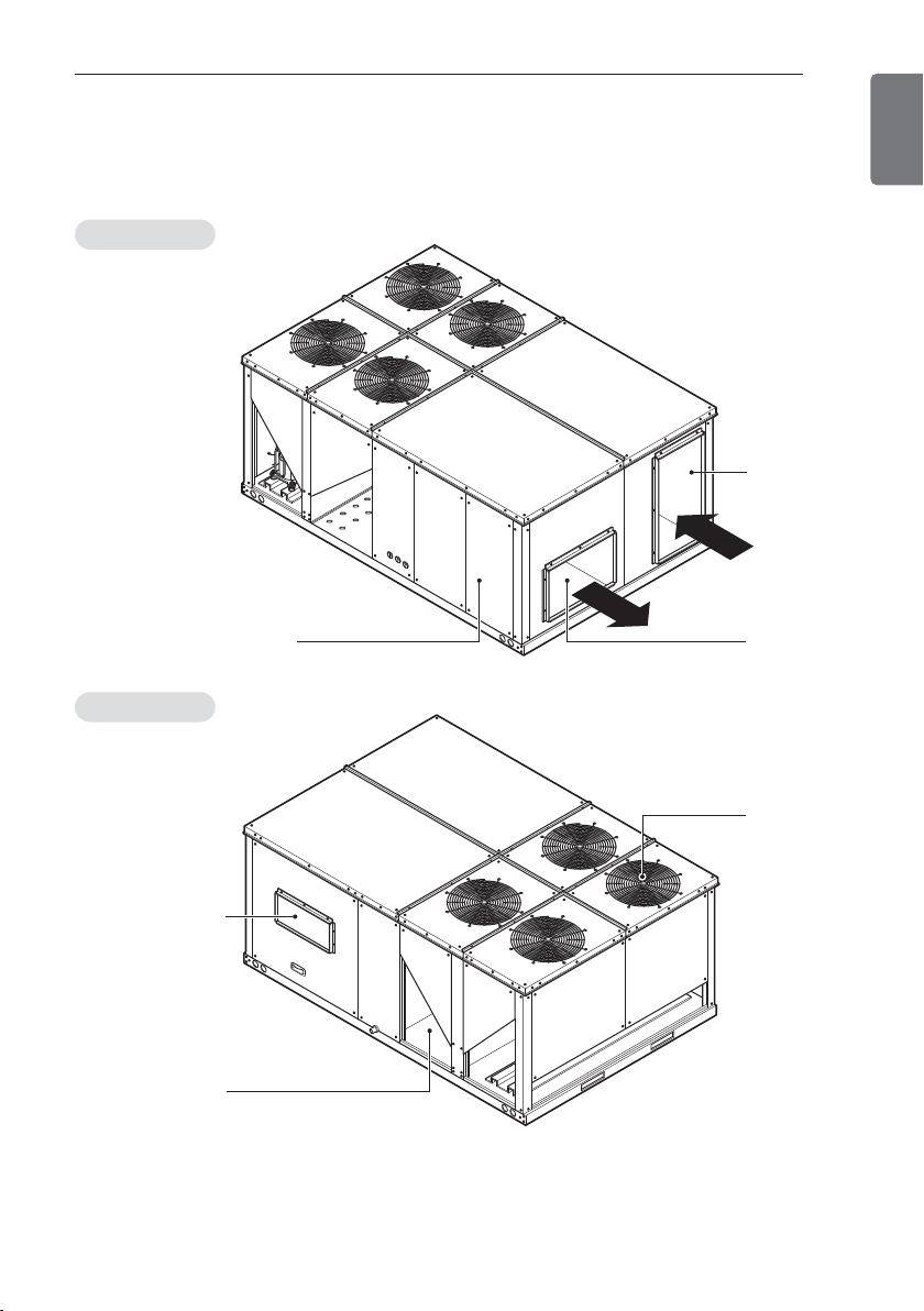
Features
Front View
Rear View
INTRODUCTION
Return
Control access panel
Refresh air
hood
Air intake vents
Supply
Air outlet
vents
8
DIMENSIONAL DATA
ENGLISH
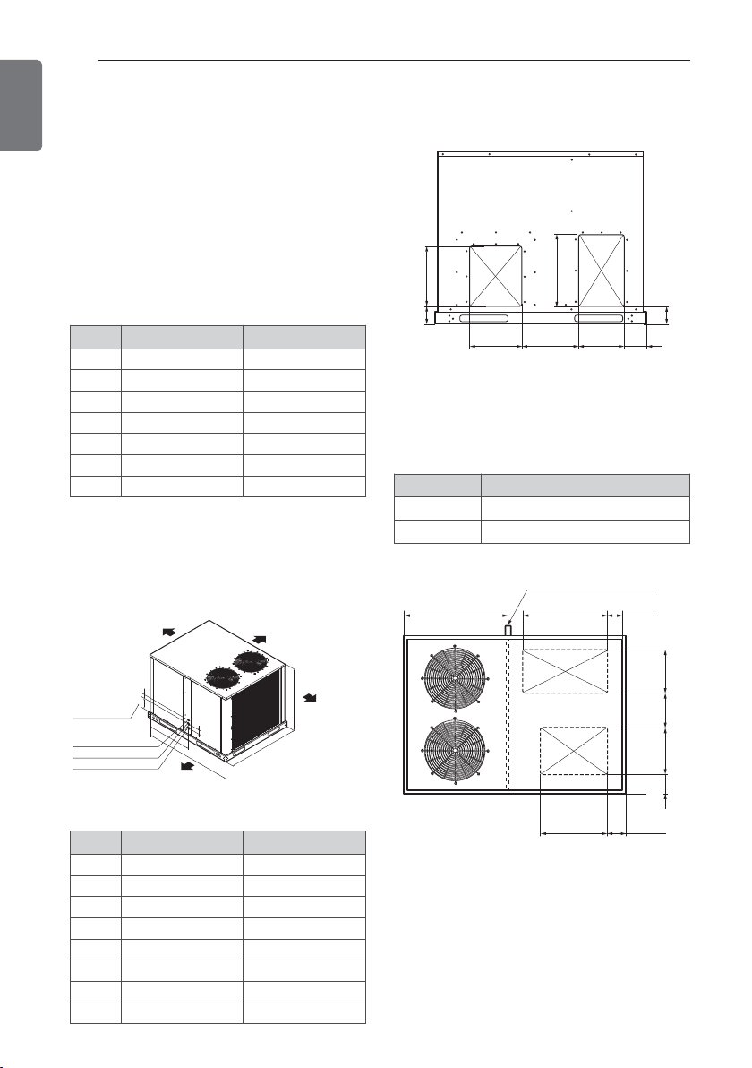
Down Flow Application Unit
(Figure 1C)
Horizontal Application Unit
(Figure 1B)
Rear view showing duct opening for horizontal
air flow.
Single packaged cooling unit are designed for
outdoor mounting with vertical condenser discharge. They can be located either at ground
level or on roof.
Each unit contains an operating charge of Refrigerant 22 as shipped.
Unit Dimensions(Figure 1A)
UNITS 6.25RT 7.5RT
A 41 15/16(1065) 42 19/32(1082)
B 43 11/16(1109) 43 11/16(1109)
C 50 13/32(1280) 64 3/16(1630)
D 29 1/2(749) 42 17/32(1080)
E 9 21/32(245) 7 5/16(185)
F 2 3/8(60) 2 3/8(60)
G 2 3/4(70) 2 15/16(70)
Figure 1A
Figure 1B
Figure 1C
UNITS 7.5RT
A 27 9/16(700)
B 18 5/16(465)
DIMENSIONAL DATA
[Unit : Inch(mm)]
UNITS 6.25RT 7.5RT
A 15 1/2(394) 14 13/16(377)
B 8 7/16(214) 94/16(235)
C 10 15/16(278) 10 15/16(278)
D 2 7/8(73) 2 7/16(62)
E 4 13/16(122) 9 6/16(136)
F 24 1/4(616) 22 9/16(700)
G 13 5/32(334) 18 5/16(465)
H 8 (203) 4 11/32(110)
[Unit : Inch(mm)]
[Unit : Inch(mm)]
Top view
CLEARANCE 36"
F
Center line of hole
1" Dia. hole control wires
1
1
/2" Dia. hole power wires
1
1
/2" Dia. hole other purpose
E
G
D
C
CLEARANCE 48"
CLEARANCE 18"
(HORIZONTAL)
CLEARANCE 32"
(DOWN FLOW)
CLEARANCE 34"
A
B
SUPPLY
G
H
A
RETURN
F
B CD
1" Condensate Location
A24 1/4(616)
RETURN
SUPPLY
B
E
29
3
/32
(99)
/16
15
10
/16
3
9
/16
9
14
/32
13
6
29
3
/32
(99)
(278)
(233)
(370)
(163)
DIMENSIONAL DATA
ENGLISH
9
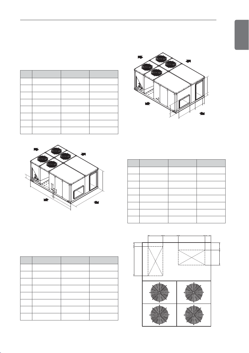
UNITS
8.5/10/12.5RT
15/17.5RT 20/25RT
A
48 5/16 (1227) 49 31/32 (1244) 49 7/32 (1250)
B
54 13/16 (1392) 60 5/8 (1540) 86 5/8 (2200)
C
85 7/16 (2170) 87 13/16 (2230) 114 3/12 (2898)
D
7 3/32 (180) 7 3/32 (180) 7 3/32 (180)
E
40 11/32 (1025) 44 1/4 (1124) 48 13/32 (1230)
F
- - 3 5/32 (80)
G
- - 3 5/32 (80)
H
3 15/16 (100) 3 15/16 (100) -
UNITS
8.5/10/12.5RT
15/17.5RT 20/25RT
A
18 7/16 (468) 18 3/4 (476) 34 5/8 (880)
B
11 31/32 (304) 14 13/32 (366) 17 5/8 (448)
C
16 10/16 (422) 17 29/32 (455) 23 5/8 (600)
D
1 15/32 (37) 2 11/16 (68) 3 31/32 (101)
E
3 15/16 (100) 5 23/32 (145) 7 5/32 (182)
F
36 21/32 (931) 37 13/32 (950) 39 3/8 (1000)
G
4 1/32 (102) 5 1/8 (130) 5 13/32 (137.5)
H
30 5/8 (778) 31 1/2 (800) 25 19/32 (650)
UNITS
8.5/10/12.5RT
15/17.5RT 20/25RT
A
15 11/32 (390) 17 29/32 (455) 23 5/8 (600)
B
12 9/16 (319) 14 11/32 (364) 15 5/8 (396)
C
18 1/2 (470) 18 3/4 (476) 34 5/8 (880)
D
6 5/16 (160) 6 31/32 (177) 6 11/16 (170)
E
2 11/16 (68) 3 27/32 (98) 6 4/8 (165)
F
35 7/16 (900) 37 13/32 (950) 39 3/8 (1000)
G
2 11/16 (68) 3 27/32 (98) 6 11/16 (170)
H
30 3/4 (781) 31 1/2 (800) 25 19/23 (650)
[Unit : Inch(mm)]
[Unit : Inch(mm)]
[Unit : Inch(mm)]
UNIT Dimensions (Figure 1D)
HORIZONTAL FLOW APPLICATION
(Figure 1E)
DOWN FLOW APPLICATION
(Figure 1F)
Figure 1D
Figure 1E
Figure 1F
D
CLEARANCE 34"
CLEARANCE 46"
CLEARANCE 16"
G
H
F
C
E
B
CLEARANCE 34"
A
CLEARANCE 34"
CLEARANCE 46"
CLEARANCE 16"
H
A
G
C
B
CLEARANCE 34"
A
B CD
F
E
D
E
F
RETURN
SUPPLY
TOP VIEW
HG
10
DIMENSIONAL DATA
ENGLISH
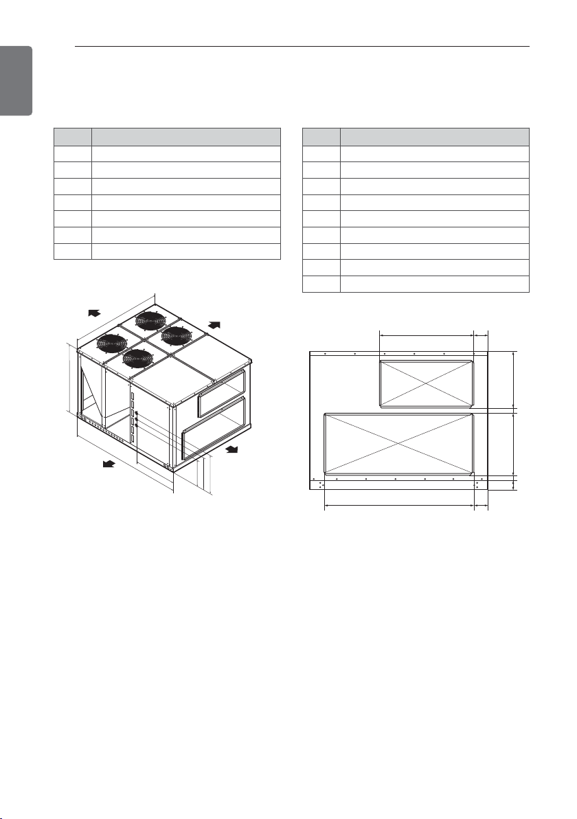
UNIT Dimensions (Figure 1G)
UNITS 30RT
A 67 11/16 (1720)
B 86 10/16 (2200)
C 105 13/16 (2688)
D 42 13/16 (1087)
E 26 12/16 (680)
F 31 8/16 (800)
G 36 4/16 (920)
[Unit : Inch(mm)]
Figure 1G
Horizontal FLOW APPLICATION
(Figure 1H)
UNITS 30RT
A 49 17/16 (1255)
B 7 9/16 (192)
C 22 1/16 (561)
D 4 6/16 (111)
E 34 13/16 (885)
F
12
/16 (19)
G 3 2/16 (80)
H 4 8/16 (115)
I 77 7/16 (1967)
[Unit : Inch(mm)]
Figure 1H
CLEARANCE 34"
B
A
C
CLEARANCE 46"
D
CLEARANCE 16"
CLEARANCE 34"
F
G
E
SUPPLY
RETURN
A
B
CE
DFG
IH
 Loading...