

SERVICE MANUAL
SERVICE MANUAL
CAUTION
BEFORE SERVICING THE UNIT, READ THE “SAFETY PRECAUTIONS”
IN THIS MANUAL.
Internal Use Only
Website http://biz.lgservice.com
DVD Home Theater System
JUNE, 2015P/NO : AFN77133590
MODEL: LHD625 (LHD625, S63S1-S, S63T1-C, S75T1-W)
MODEL: LHD625
(LHD625, S63S1-S, S63T1-C, S75T1-W)

CONTENTS
SECTION 1 ........ SUMMARY
SECTION 2 ........ ELECTRICAL
SECTION 3 ........ CABINET & MAIN CHASSIS
SECTION 4 ........ REPLACEMENT PARTS LIST
1-1

SECTION 1
SUMMARY
CONTENTS
SERVICING PRECAUTIONS ............................................................................................................................ 1-3
ESD PRECAUTIONS ......................................................................................................................................... 1-5
HIDDEN KEY MODE ......................................................................................................................................... 1-6
FIRMWARE UPGRADE GUIDE ........................................................................................................................ 1-8
SPECIFICATIONS ........................................................................................................................................... 1-10
1-2

SERVICING PRECAUTIONS
NOTES REGARDING HANDLING OF THE PICK-UP
1. Notes for transport and storage
1) The pick-up should always be left in its conductive bag until immediately prior to use.
2) The pick-up should never be subjected to external pressure or impact.
Storage in conductive bag
Drop impact
2. Repair notes
1) The pick-up incorporates a strong magnet, and so should never be brought close to magnetic materials.
2) The pick-up should always be handled correctly and carefully, taking care to avoid external pressure and
impact. If it is subjected to strong pressure or impact, the result may be an operational malfunction and/or
damage to the printed-circuit board.
3) Each and every pick-up is already individually adjusted to a high degree of precision, and for that reason
the adjustment point and installation screws should absolutely never be touched.
4) Laser beams may damage the eyes!
Absolutely never permit laser beams to enter the eyes!
Also NEVER switch ON the power to the laser output part (lens, etc.) of the pick-up if it is damaged.
NEVER look directly at the laser beam, and don’t allow
contact with fingers or other exposed skin.
5) Cleaning the lens surface
If there is dust on the lens surface, the dust should be cleaned away by using an air bush (such as used
for camera lens). The lens is held by a delicate spring. When cleaning the lens surface, therefore, a cotton swab should be used, taking care not to distort lens.
Pressure
Magnet
How to hold the pick-up
Cotton swab
Conductive Sheet
6) Never attempt to disassemble the pick-up.
Spring has excess pressure. If the lens is extremely dirty, apply isopropyl alcohol to the cotton swab.
(Do not use any other liquid cleaners, because they will damage the lens.) Take care not to use too much
of this alcohol on the swab, and do not allow the alcohol to get inside the pick-up.
1-3
Pressure

NOTES REGARDING COMPACT DISC PLAYER REPAIRS
1. Preparations
1) Compact disc players incorporate a great many ICs as well as the pick-up (laser diode). These components
are sensitive to, and easily affected by, static electricity. If such static electricity is high voltage, components
can be damaged, and for that reason components should be handled with care.
2) The pick-up is composed of many optical components and other high-precision components. Care must be
taken, therefore, to avoid repair or storage where the temperature or humidity is high, where strong magnetism is present, or where there is excessive dust.
2. Notes for repair
1) Before replacing a component part, first disconnect the power supply lead wire from the unit
2) All equipment, measuring instruments and tools must be grounded.
3) The workbench should be covered with a conductive sheet and grounded.
When removing the laser pick-up from its conductive bag, do not place the pick-up on the bag. (This is
because there is the possibility of damage by static electricity.)
4) To prevent AC leakage, the metal part of the soldering iron should be grounded.
5) Workers should be grounded by an armband (1 M)
6) Care should be taken not to permit the laser pick-up to come in contact with clothing, in order to prevent
static electricity changes in the clothing to escape from the armband.
7) The laser beam from the pick-up should NEVER be directly facing the eyes or bare skin.
Armband
Resistor
(1 M)
Resistor
(1 M)
CAUTION: CLASS 1M VISIBLE AND INVISIBLE LASER RADIATION WHEN
OPEN. DO NOT VIEW DIRECTLY WITH OPTICAL INSTRUMENTS
Use of controls, adjustments or the performance of procedures other than
those specified herein may result in hazardous radiation exposure.
Conductive
Sheet
1-4
ESD PRECAUTIONS
Electrostatically Sensitive Devices (ESD)
Some semiconductor (solid state) devices can be damaged easily by static electricity. Such components
commonly are called Electrostatically Sensitive Devices (ESD). Examples of typical ESD devices are integrated
circuits and some field-effect transistors and semiconductor chip components. The following techniques should
be used to help reduce the incidence of component damage caused by static electricity.
1. Immediately before handling any semiconductor component or semiconductor-equipped assembly, drain off
any electrostatic charge on your body by touching a known earth ground. Alternatively, obtain and wear a
commercially available discharging wrist strap device, which should be removed for potential shock reasons
prior to applying power to the unit under test.
2. After removing an electrical assembly equipped with ESD devices, place the assembly on a conductive surface
such as aluminum foil, to prevent electrostatic charge buildup or exposure of the assembly.
3. Use only a grounded-tip soldering iron to solder or unsolder ESD devices.
4. Use only an anti-static solder removal device. Some solder removal devices not classified as "anti-static" can
generate electrical charges sufficient to damage ESD devices.
5. Do not use freon-propelled chemicals. These can generate electrical charges sufficient to damage ESD
devices.
6. Do not remove a replacement ESD device from its protective package until immediately before you are
ready to install it. (Most replacement ESD devices are packaged with leads electrically shorted together by
conductive foam, aluminum foil or comparable conductive materials).
7. Immediately before removing the protective material from the leads of a replacement ESD device, touch the
protective material to the chassis or circuit assembly into which the device will by installed.
CAUTION : BE SURE NO POWER IS APPLIED TO THE CHASSIS OR CIRCUIT, AND OBSERVE ALL OTHER
SAFETY PRECAUTIONS.
8. Minimize bodily motions when handing unpackaged replacement ESD devices. (Otherwise harmless motion
such as the brushing together of your clothes fabric or the lifting of your foot from a carpeted floor can generate
static electricity sufficient to damage an ESD device).
CAUTION. GRAPHIC SYMBOLS
THE LIGHTNING FLASH WITH APROWHEAD SYMBOL. WITHIN AN EQUILATERAL TRIANGLE, IS
INTENDED TO ALERT THE SERVICE PERSONNEL TO THE PRESENCE OF UNINSULATED
“DANGEROUS VOLTAGE” THAT MAY BE OF SUFFICIENT MAGNITUDE TO CONSTITUTE A RISK OF
ELECTRIC SHOCK.
THE EXCLAMATION POINT WITHIN AN EQUILATERAL TRIANGLE IS INTENDED TO ALERT THE
SERVICE PERSONNEL TO THE PRESENCE OF IMPORTANT SAFETY INFORMATION IN SERVICE
LITERATURE.
1-5
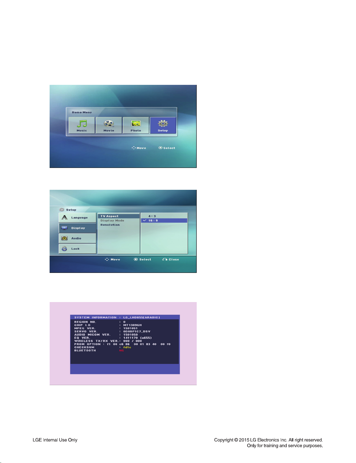
HIDDEN KEY MODE
1. DISPLAY SYSTEM INFORMATION
1) Change function to DVD/CD by pressing input key, and wait until home menu is shown.
- Do not insert disc or USB at the set.
2) Go to SETUP menu by pressing SETUP button in HOME menu.
3) Move highlight at "DISPLAY -> TV Aspect -> 16:9".
4) Press "1 -> 3 -> 9 -> 7 -> 1 -> 3 -> 9 -> ENTER" in order.
5) and then, system reset menu is displayed.
6) Power off and on by pressing POWER key.
1-6

2. EEPROM EDIT
1) Change function to DVD/CD by pressing input key, and wait until home menu is shown.
- Do not insert disc or USB at the set.
2) Press "PAUSE -> 1 -> 4 -> 7 -> 2" in order.
3) and then, option setting menu is displayed.
You can see 10 bytes option value.
4) Move a cursor by pressing Arrow < > key.
5) Press number 0 ~ 9, character a ~ f (1 ~ 6 for a while) for more than 5 seconds
6) Press "PAUSE" key to exit option setting menu.
After change option value, you need to make system reset.
3. DOOR LOCK / UNLOCK
1) Press Front “STOP” + Remote control “STOP” for more than 5 seconds.
2) “LOCKED” / “UNLOCKED” display on the VFD.
1-7

FIRMWARE UPGRADE GUIDE
1. MPEG
1) Copy fi rmware to USB (Do not change fi le name).
Ex) LG_LHD655LD7_1501051.rom
2) Change function to DVD/CD by pressing input key, and wait until home menu is shown.
3) Inset USB device which includes fi rmware.
4) Firmware is detected automatically and then, shows blue screen in TV.
If home menu is maintained after inserting USB, press music icon.
5) Take off the USB and press PLAY key.
6) and then, upgrading is started.
- Do not turn off the set until upgrade is fi nished.
7) After fi nishing fi rmware upgrading, set will restart automatically.
8) Power off and on again by pressing POWER key.
1-8
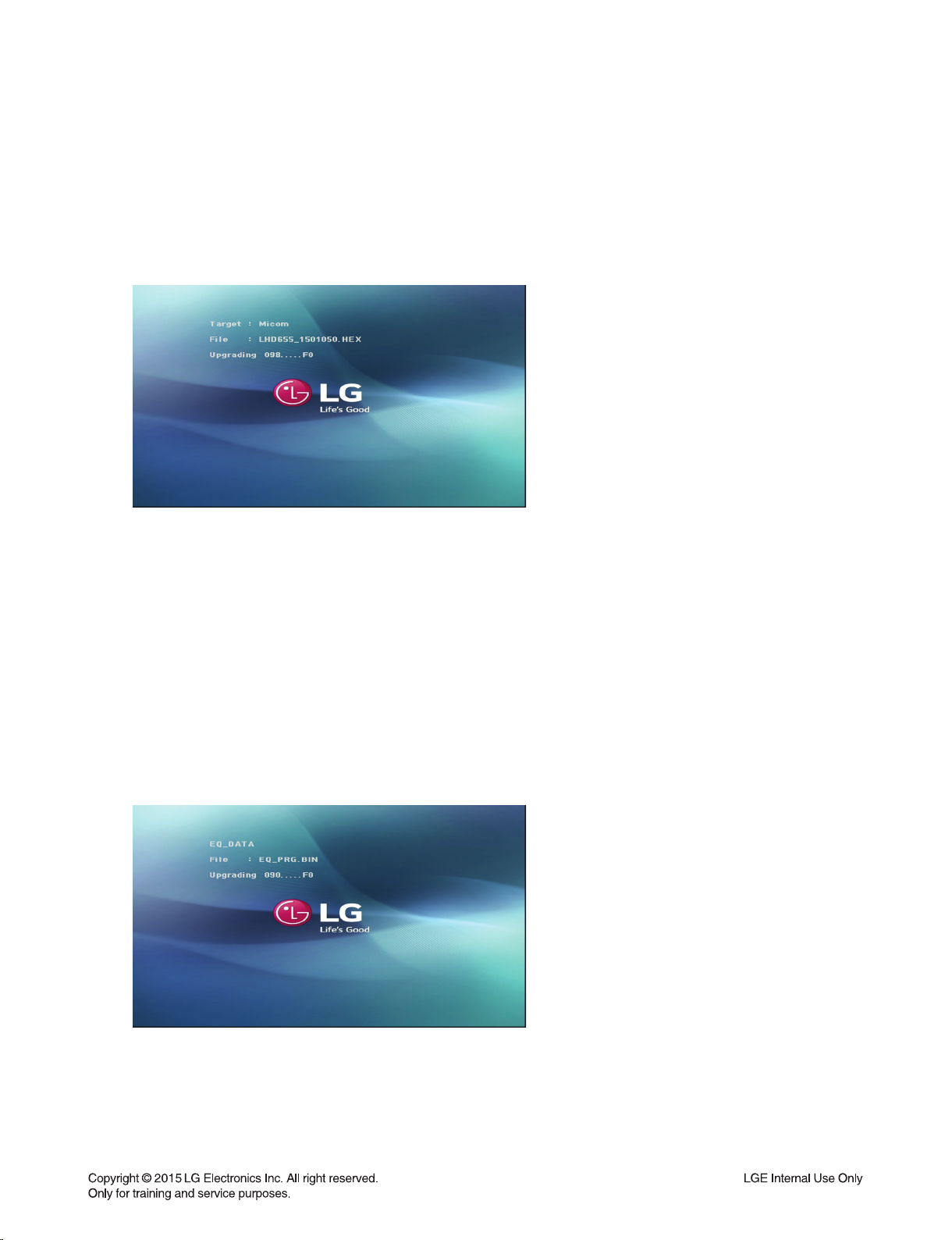
2. AUDIO MICOM
1) Copy fi rmware to USB (Do not change fi le name).
Ex) LHD655_1501050.HEX
2) Change function to DVD/CD by pressing input key, and wait until home menu is shown.
3) Inset USB device which includes fi rmware.
4) Firmware is detected automatically and then, shows blue screen in TV.
If home menu is maintained after inserting USB, press music icon.
5) Upgrading is started.
- Do not turn off the set until upgrade is fi nished.
- Do not pull out the USB device using fi rmware upgrading.
6) After fi nishing fi rmware upgrading, set will be turned off.
3. EQ
1) Copy fi rmware to USB (Do not change fi le name).
Ex) EQ_PRG.BIN
2) Change function to DVD/CD by pressing input key, and wait until home menu is shown.
3) Inset USB device which includes fi rmware.
4) Firmware is detected automatically and then, shows blue screen in TV.
If Home menu is maintained after inserting USB, press music icon.
5) Upgrading is started.
- Do not turn off the set until upgrade is fi nished.
- Do not pull out the USB device using fi rmware upgrading.
6) After fi nishing fi rmware upgrading, set will be turned off.
1-9

SPECIFICATIONS
• GENERAL
Power requirements Refer to main label.
Power consumption Refer to main label.
Networked standby 0.4 W (If all network ports are activated.)
Dimensions (W x H x D) (360 x 60.5 x 299) mm without foot
Net Weight (Approx.) 2.69 kg
Operating temperature 5 °C to 35 °C
Operating humidity 5 % to 90 %
Bus Power Supply 5 V 500 mA
• INPUTS/ OUTPUTS
VIDEO OUT 1.0 V (p-p), 75 Ω, sync negative, RCA jack x 1
HDMI OUT (video/audio) 19 pin (Type A, HDMI™ Connector ) x 1
ANALOG AUDIO IN 2.0 Vrms (1 kHz, 0 dB), 600 Ω, RCA jack (L, R) x 1
DIGITAL IN (OPTICAL) 3 V (p-p), Optical jack x 1
PORT. IN 0.5 Vrms (3.5 mm stereo jack) x 1
• AMPLIFIER
Stereo mode 167 W + 167 W (3 Ω at 1kHz)
Surround mode Front 167 W + 167 W (3 Ω at 1 kHz)
Center 167 W (3 Ω at 1 kHz)
Surround 167 W + 167 W (3 Ω at 1 kHz))
Subwoofer 167 W (3 Ω at 60 Hz)
• TUNER
FM Tuning Range 87.5 to 108.0 MHz or 87.50 to 108.00 MHz
1-10

• SPEAKERS
Front Speaker
Type 1 Way 1 speaker
Impedance Rated 3 Ω
Input Power 167 W
Max. Input Power 334 W
Net Dimensions (W x H x D) (88 x 122 x 81) mm
Net Weight 0.5 kg
Rear Speaker
Type 1 Way 1 speaker
Impedance Rated 3 Ω
Input Power 167 W
Max. Input Power 334 W
Net Dimensions (W x H x D) (88 x 122 x 81) mm
Net Weight 0.5 kg
Center Speaker
Type 1 Way 1 speaker
Impedance Rated 3 Ω
Input Power 167 W
Max. Input Power 334 W
Net Dimensions (W x H x D) (260 x 93 x 74) mm
Net Weight 0.6 kg
Passive Subwoofer
Type 1 Way 1 speaker
Impedance Rated 3 Ω
Input Power 167 W
Max. Input Power 334 W
Net Dimensions (W x H x D) (190 x 385 x 318) mm
Net Weight 5.0 kg
• Design and specifications are subject to change without notice.
1-11

1-12

SECTION 2
ELECTRICAL
CONTENTS
DIGITAL DISPLAY & MEDIA TRAINING MASTER ......................................................................................... 2-2
1. DISTORTED PICTURE ........................................................................................................................... 2-2
2. NO PICTURE .......................................................................................................................................... 2-7
3. PICTURE COLOR ................................................................................................................................. 2-12
4. NOISE/AUDIO PROBLEMS .................................................................................................................. 2-14
5. MISCELLANEOUS ................................................................................................................................ 2-17
ONE POINT REPAIR GUIDE .......................................................................................................................... 2-26
1. NO POWER PROBLEM ....................................................................................................................... 2-26
2. NO BOOTING WHEN YOU TURN THE UNIT ON, NO MESSAGE ON FRONT PANEL.................... 2-28
3. BAD HDMI VIDEO / AUDIO OUTPUT .................................................................................................. 2-34
4. NO AUDIO FROM SPEAKER ............................................................................................................... 2-35
5. NO USB ................................................................................................................................................ 2-36
6. BT CONNECTION ERROR .................................................................................................................. 2-37
ELECTRICAL TROUBLESHOOTING GUIDE ................................................................................................. 2-38
1. SYSTEM POWER SUPPLY ON SMPS BOARD .................................................................................. 2-38
2. POWER SUPPLY ON MAIN BOARD ................................................................................................... 2-41
3. SYSTEM PART ..................................................................................................................................... 2-43
4. NO HDMI OUTPUT ............................................................................................................................... 2-45
5. NO AUDIO OUTPUT ............................................................................................................................ 2-46
DETAILS AND WAVEFORMS ON SYSTEM TEST AND DEBUGGING ....................................................... 2-47
1. SYSTEM PART (MPEG CRYSTAL 27 MHz) ....................................................................................... 2-47
2. SDRAM CLOCK .................................................................................................................................... 2-48
3. VIDEO PART (100% FULL COLOR-BAR) ........................................................................................... 2-48
4. HDMI PART .......................................................................................................................................... 2-49
5. SERVO OPEN/CLOSE SIGNAL ........................................................................................................... 2-50
WIRING DIAGRAM .......................................................................................................................................... 2-59
BLOCK DIAGRAM .......................................................................................................................................... 2-61
CIRCUIT DIAGRAMS ...................................................................................................................................... 2-63
1. SMPS CIRCUIT DIAGRAM .................................................................................................................. 2-63
2. MAIN & AMP - MPEG CIRCUIT DIAGRAM ......................................................................................... 2-65
3. MAIN & AMP - SERVO CIRCUIT DIAGRAM ....................................................................................... 2-67
4. MAIN & AMP - I/O CIRCUIT DIAGRAM ............................................................................................... 2-69
5. MAIN & AMP - MICOM CIRCUIT DIAGRAM........................................................................................ 2-71
6. MAIN & AMP - PWM CIRCUIT DIAGRAM ........................................................................................... 2-73
7. MAIN & AMP - AMP CIRCUIT DIAGRAM ............................................................................................ 2-75
8. JACK CIRCUIT DIAGRAM ................................................................................................................... 2-77
9. FRONT CIRCUIT DIAGRAM ................................................................................................................ 2-79
CIRCUIT VOLTAGE CHART ........................................................................................................................... 2-81
1. ICs ......................................................................................................................................................... 2-81
2. CAPACITORS ....................................................................................................................................... 2-81
3. CONNECTORS ..................................................................................................................................... 2-82
PRINTED CIRCUIT BOARD DIAGRAMS ....................................................................................................... 2-83
1. SMPS P. C. BOARD ............................................................................................................................. 2-83
2. MAIN & AMP P. C. BOARD .................................................................................................................. 2-85
3. JACK P. C. BOARD .............................................................................................................................. 2-87
4. FRONT P. C. BOARD ........................................................................................................................... 2-87
2-1
DIGITAL DISPLAY & MEDIA TRAINING MASTER
Objective: To provide clear and concise guidelines for customer service agents to handle calls on
box goods calls.
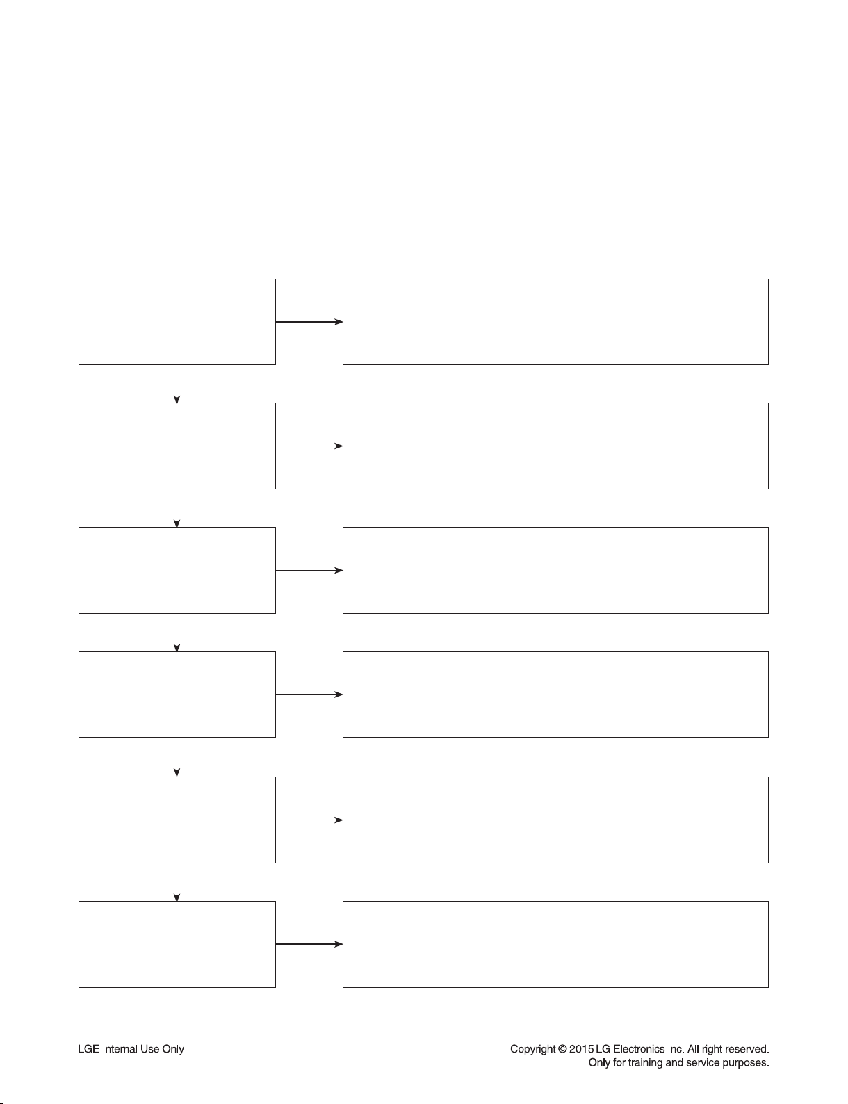
1. DISTORTED PICTURE
1-1. Lines on Picture
Distorted picture refers to the customer getting video, but there is a problem with the video.
Determine what cables the customer is using to connect
What cables is
the customer using to
connect the DVD?
YES
NO
the DVD to the TV and if connected properly. Refer to OM for
connections. Tighten any loose cables. Make sure the customer
is not connecting a DVD to VCR.
Copy protection can distort the picture on older DVD models.
Is the TV set
to the correct input?
YES
Do lines appear when
watching multiple discs?
YES
Do lines appear when
watching a TV program?
YES
Do lines appear
when the DVD is
connected to another TV?
NO
NO
NO
NO
Make sure the TV is on the correct input.
Turn TV off, then on to determine input.
Video when using composite, or component.
DVI when using DVI, and HDMI when using HDMI.
One disc displaying the issue is a problem with the disc.
Multiple discs displaying the problem could indicate the DVD lens
needs to be cleaned. Recommend the customer use a lens
cleaner on the DVD. A lens cleaner is available at any local
electronics retailer.
Lines appearing when watching a TV program indicates
an issue with the display. If the TV program is fine,
then connect the DVD to another input on the display to
determine if the problem is following the DVD.
Connect the DVD to another TV and play a disc.
No lines during disc play back indicates a problem with the first TV.
Please refer to the owners manual for instructions on how to
connect the DVD to a TV. If the DVD has a problem on the
second TV, then see service chart for service information.
YES
Has the customer tried
another set of cables?
NO
Have the customer try another set of cables. A bad cable can
also cause video problems. Test the cable with another device to
the TV to also determine if the TV is bad. If DVD is problem,
please see service chart for service information.
2-2

DIGITAL DISPLAY & MEDIA TRAINING MASTER
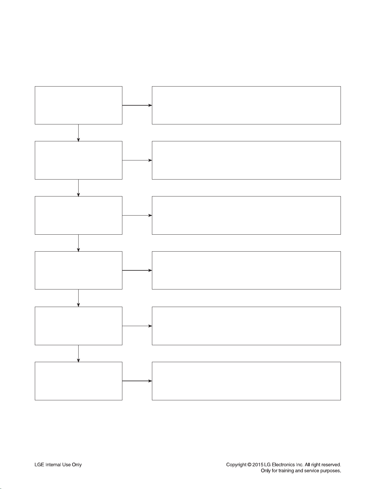
1-2. Ghost Picture
Distorted picture refers to the customer getting video, but there is a problem with the video.
Determine what cables the customer is using to connect the DVD to
What cables is the customer
using to connect the DVD?
YES
NO
the TV and if connected properly. Refer to OM for connections.
Tighten any loose cables. Make sure the customer is not connecting a
DVD to VCR or DVD. Copy protection can distort
the picture on older VCR models.
Is the TV set to
the correct input?
YES
Do ghosting appear when
watching multiple discs?
YES
Do lines appear when
watching a TV program?
YES
Does ghosting
appear when the DVD is
connected to another TV?
NO
NO
NO
NO
Make sure the TV is on the correct input. Turn TV off,
then on to determine input. Video when using composite,
or component. DVI when using DVI, and HDMI when using HDMI.
One disc displaying the issue is a problem with the disc.
Multiple discs displaying the problem could indicate the DVD lens
needs to be cleaned. Recommend the customer use a lens cleaner
on the DVD. A lens cleaner is available at any local electronics retailer.
Ghosting appearing when watching a TV program indicates an
issue with the display. If the TV program is fine, then connect
the DVD to another input on the display to determine
if the problem is following the DVD.
Connect the DVD to another TV and play a disc.
No ghosting during disc play back indicates a problem with the first TV.
Please refer to the owners manual for instructions on how to
connect the DVD to a TV. If the DVD has a problem on the second TV,
then see service chart for service information.
YES
Has the customer tried
another set of cables?
NO
Have the customer try another set of cables. A bad cable can
also cause video problems. Test the cable with another device to
the TV to also determine if the TV is bad. If DVD is problem,
please see service chart for service information.
2-3

DIGITAL DISPLAY & MEDIA TRAINING MASTER
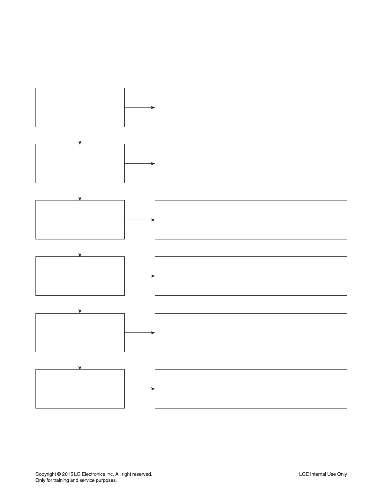
1-3. Rolling Picture
Distorted picture refers to the customer getting video, but there is a problem with the video.
Determine what cables the customer is using to connect the DVD to
What cables is the customer
using to connect the DVD?
YES
NO
the TV and if connected properly. Refer to OM for connections.
Tighten any loose cables. Make sure the customer is not connecting
a DVD to VCR. Copy protection can distort
the picture on older VCR models.
Is the TV set to
the correct input?
YES
Does rolling appear when
watching multiple discs?
YES
Does rolling appear when
watching a TV program?
YES
Does rolling appear
when the DVD is connected to
another TV?
NO
NO
NO
NO
Make sure the TV is on the correct input. Turn TV off,
then on to determine input. Video when using composite,
or component. DVI when using DVI, and HDMI when using HDMI.
One disc displaying the issue is a problem with the disc.
Multiple discs displaying the problem could indicate the DVD lens
needs to be cleaned. Recommend the customer use a lens cleaner
on the DVD. A lens cleaner is available at any local electronics retailer.
Rolling appearing when watching a TV program indicates
an issue with the display. If the TV program is fine, then connect
the DVD to another input on the display to determine if the problem
is following the DVD.
Connect the DVD to another TV and play a disc. No lines during disc
playback indicates a problem with the first TV.
Please refer to the owners manual for instructions on how to connect the
DVD to a TV. If the DVD has a problem on the second TV,
then see service chart for service information.
YES
Has the customer tried
another set of cables?
NO
Have the customer try another set of cables. A bad cable can also
cause video problems. Test the cable with another device to the TV
to also determine if the TV is bad. If DVD is problem,
please see service chart for service information.
2-4

DIGITAL DISPLAY & MEDIA TRAINING MASTER
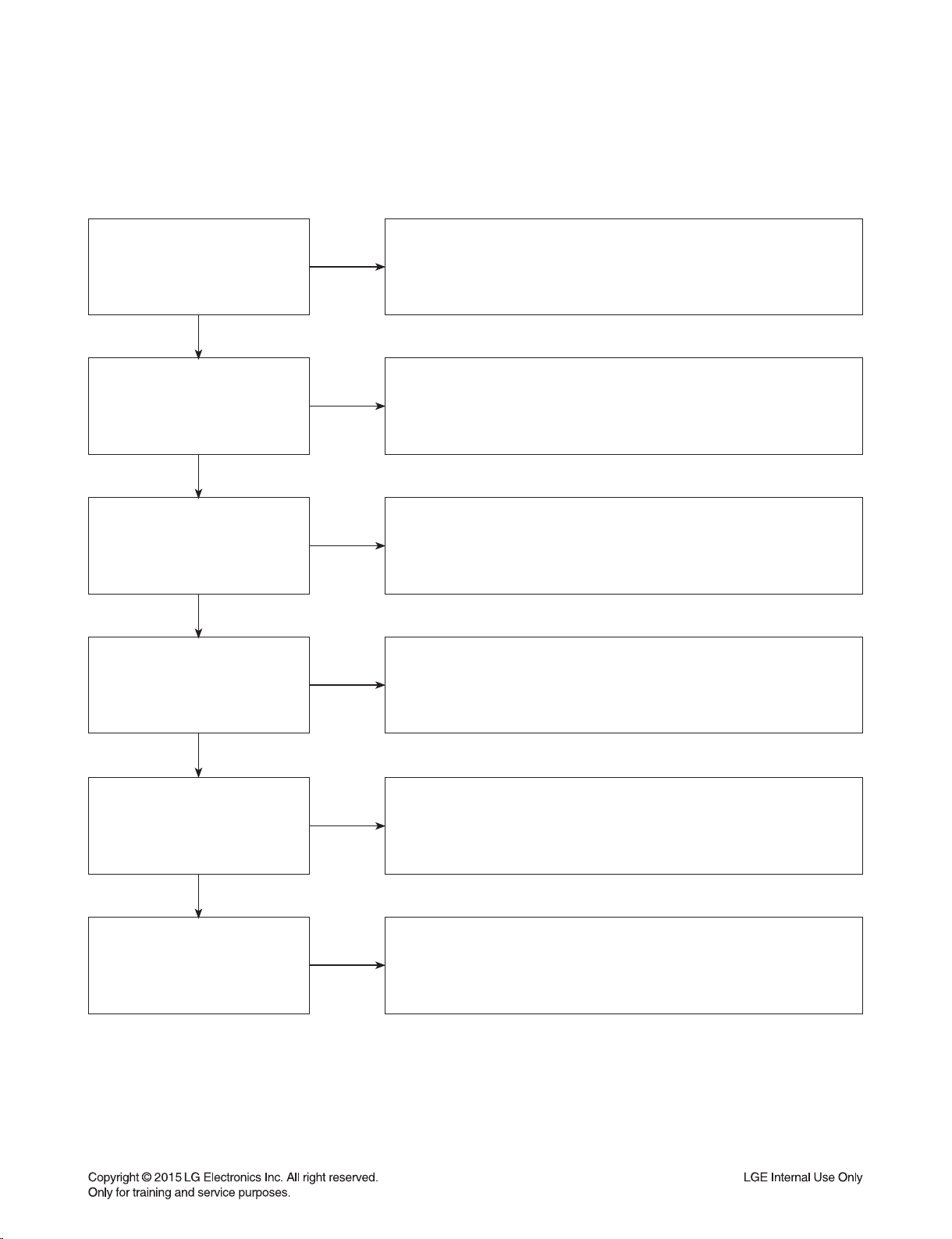
1-4. Shaky Picture
Distorted picture refers to the customer getting video, but there is a problem with the video.
Determine what cables the customer is using to connect the DVD to
What cables is the customer
using to connect the DVD?
YES
NO
the TV and if connected properly. Refer to OM for connections.
Tighten any loose cables.
Make sure the customer is not connecting a DVD.
Copy protection can distort the picture on older VCR models.
Is the TV set to
the correct input?
YES
Does shaking appear when
watching multiple discs?
YES
Does shaking appear when
watching a TV program?
YES
Does shaking appear
when the DVD is connected to
another TV?
NO
NO
NO
NO
Make sure the TV is on the correct input. Turn TV off, then on
to determine input. Video when using composite, or component.
DVI when using DVI, and HDMI when using HDMI.
One disc displaying the issue is a problem with the disc.
Multiple discs displaying the problem could indicate the DVD lens
needs to be cleaned. Recommend the customer use a lens cleaner
on the DVD. A lens cleaner is available at any local electronics retailer.
Shaking appearing when watching a TV program indicates an issue with
the display. If the TV program is fine, then connect the DVD to another
input on the display to determine if the problem is following the DVD.
Connect the DVD to another TV and play a disc. No shaking during
disc play back indicates a problem with the first TV. Please refer to
the owners manual for instructions on how to connect the DVD to a TV.
If the DVD has a problem on the second TV,
then see service chart for service information.
YES
Has the customer tried
another set of cables?
NO
Have the customer try another set of cables. A bad cable can
also cause video problems. Test the cable with another device to
the TV to also determine if the TV is bad. If DVD is problem,
please see service chart for service information.
2-5
DIGITAL DISPLAY & MEDIA TRAINING MASTER
1-5. Blurry Picture
Distorted picture refers to the customer getting video, but there is a problem with the video.
Determine what cables the customer is using to connect the DVD to
What cables is the customer
using to connect the DVD?
YES
NO
the TV and if connected properly. Refer to OM for connections.
Tighten any loose cables. Make sure the customer is not connecting
a DVD to VCR. Copy protection can distort
the picture on older VCR models.
Is the TV set to
the correct input?
YES
Does blurriness appear when
watching multiple discs?
YES
Does blurriness appear when
watching a TV program?
YES
Does blurriness appear
when the DVD is connected to
another TV?
NO
NO
NO
NO
Make sure the TV is on the correct input. Turn TV off,
then on to determine input. Video when using composite, or component.
DVI when using DVI, and HDMI when using HDMI.
One disc displaying the issue is a problem with the disc.
Multiple discs displaying the problem could indicate the DVD lens
needs to be cleaned. Recommend the customer use a lens cleaner on
the DVD. A lens cleaner is available at any local electronics retailer.
Blurriness appearing when watching a TV program indicates an
issue with the display. If the TV program is fine, then connect
the DVD to another input on the display to determine if the problem
is following the DVD.
Connect the DVD to another TV and play a disc. No blurriness
during disc play back indicates a problem with the first TV.
Please refer to the owners manual for instructions on how to connect
the DVD to a TV. If the DVD has a problem on the second TV,
then see service chart for service information.
YES
Has the customer tried
another set of cables?
NO
Have the customer try another set of cables.
A bad cable can also cause video problems. Test the cable with another
device to the TV to also determine if the TV is bad. If DVD is problem,
please see service chart for service information.
2-6
DIGITAL DISPLAY & MEDIA TRAINING MASTER
2. NO PICTURE
2-1. Black Screen
The entire screen is black.
Does the DVD on-screen
menu appear?
YES
What cables is the customer
using to connect the DVD?
YES
Is the TV set to
the correct input?
YES
Is the customer able to
watch TV programming?
NO
NO
NO
NO
Make sure the customer did not select 480i resolution in the menu
of the DVD HTS if using HDMI connections. Change resolution on
upconversion DVD HTS by pushing the resolution button of the remote
controller. HDMI don’t support 480i resolution.
Determine what cables the customer is using to connect the DVD to
the TV and if connected properly. Refer to OM for connections.
Tighten any loose cables. Make sure the customer is not connecting a
DVD to VCR. Copy protection can distort
the picture on older VCR models.
Make sure the TV is on the correct input. Turn TV off,
then on to determine input. Video when using composite, or component.
DVI when using DVI, and HDMI when using HDMI.
If the customer is not able to watch television then he may have a
problem with his television, especially if the cable signal comes
through on a different input. If the customer can not get a TV program,
then he still may have a problem with the particular input on his TV.
YES
Can the customer connect
the DVD to another TV?
YES
Has the customer tried
another set of cables?
NO
NO
Have the customer connect the DVD to another TV in order to
determine if the problem is the DVD or the TV. Refer to the OM for
connections assistance. If the DVD works on the second TV,
then the customer has a problem with his TV.
Have the customer try another set of cables. A bad cable can
also cause video problems. Test the cable with another device to the TV
to also determine if the TV is bad. If DVD is problem,
please see service chart for service information.
2-7

DIGITAL DISPLAY & MEDIA TRAINING MASTER
2-2. Blue Screen
The entire screen is a solid blue color.
Does the DVD on-screen
menu appear?
YES
What cables is the customer
using to connect the DVD?
YES
Is the TV set to
the correct input?
YES
Is the customer able to
watch TV programming?
NO
NO
NO
NO
Make sure the customer did not select 480i resolution in the menu
of the DVD HTS if using HDMI connections. Change resolution on
upconversion DVD HTS by pushing the resolution button of the remote
controller. HDMI don’t support 480i resolution.
Determine what cables the customer is using to connect the DVD
to the TV and if connected properly. Refer to OM for connections.
Tighten any loose cables. Make sure the customer is not connecting a
DVD to VCR. Copy protection can distort
the picture on older VCR models.
Make sure the TV is on the correct input.
Turn TV off, then on to determine input. Video when using composite,
or component. DVI when using DVI, and HDMI when using HDMI.
If the customer is not able to watch television then he may have a
problem with his television, especially if the cable signal comes
through on a different input. If the customer can not get a TV program,
then he still may have a problem with the particular input on his TV.
YES
Can the customer connect
the DVD to another TV?
YES
Has the customer tried
another set of cables?
NO
NO
Have the customer connect the DVD to another TV in order to
determine if the problem is the DVD or the TV. Refer to the OM for
connections assistance. If the DVD works on the second TV,
then the customer has a problem with his TV.
Have the customer try another set of cables. A bad cable can also
cause video problems. Test the cable with another device to
the TV to also determine if the TV is bad. If DVD is problem,
please see service chart for service information.
2-8

DIGITAL DISPLAY & MEDIA TRAINING MASTER
2-3. Snowy Screen
A snowy picture is when black and white dots are all over the screen.
Does the DVD on-screen
menu appear?
YES
What cables is the customer
using to connect the DVD?
YES
Is the TV set to
the correct input?
YES
Is the customer able to
watch TV programming?
NO
NO
NO
NO
Make sure the customer did not select 480i resolution in the menu
of the DVD HTS if using HDMI connections. Change resolution on
upconversion DVD HTS by pushing the resolution button of the remote
controller. HDMI don’t support 480i resolution.
Determine what cables the customer is using to connect the DVD
to the TV and if connected properly. Refer to OM for connections.
Tighten any loose cables. Make sure the customer is not connecting a
DVD to VCR. Copy protection can distort
the picture on older VCR models.
Make sure the TV is on the correct input. Turn TV off,
then on to determine input. Video when using composite, or component.
DVI when using DVI, and HDMI when using HDMI.
If the customer is not able to watch television then he may
have a problem with his television, especially if the cable signal comes
through on a different input. If the customer can not get a TV program,
then he still may have a problem with the particular input on his TV.
YES
Can the customer connect
the DVD to another TV?
YES
Has the customer tried
another set of cables?
NO
NO
Have the customer connect the DVD to another TV in order to
determine if the problem is the DVD or the TV. Refer to the OM for
connections assistance. If the DVD works on the second TV,
then the customer has a problem with his TV.
Have the customer try another set of cables. A bad cable can
also cause video problems. Test the cable with another device to
the TV to also determine if the TV is bad. If DVD is problem,
please see service chart for service information.
2-9

DIGITAL DISPLAY & MEDIA TRAINING MASTER
2-4. No Signal
A “no signal” message appears on the screen of the display.
Does the DVD on-screen
menu appear?
YES
What cables is the customer
using to connect the DVD?
YES
Is the TV set to the
correct input?
YES
Is the customer able to
watch TV programming?
NO
NO
NO
NO
Make sure the customer did not select 480i resolution in the
menu of the DVD HTS if using HDMI connections. Change resolution on
upconversion DVD HTS by pushing the resolution button of the remote
controller. HDMI don’t support 480i resolution.
Determine what cables the customer is using to connect the DVD
to the TV and if connected properly. Refer to OM for connections.
Tighten any loose cables. Make sure the customer is not connecting
a DVD to VCR or DVD to DVD Recorder.
Copy protection can distort the picture on older VCR models.
Make sure the TV is on the correct input. Turn TV off,
then on to determine input. Video when using composite, or component.
DVI when using DVI, and HDMI when using HDMI.
If the customer is not able to watch television then he may have a
problem with his television, especially if the cable signal comes
through on a different input. If the customer can not get a TV program,
then he still may have a problem with the particular input on his TV.
YES
Can the customer connect
the DVD to another TV?
YES
Has the customer tried
another set of cables?
NO
NO
Have the customer connect the DVD to another TV in order to
determine if the problem is the DVD or the TV. Refer to the OM for
connections assistance. If the DVD works on the second TV,
then the customer has a problem with his TV.
Have the customer try another set of cables. A bad cable
can also cause video problems. Test the cable with another device to
the TV to also determine if the TV is bad. If DVD is problem,
please see service chart for service information.
2-10

DIGITAL DISPLAY & MEDIA TRAINING MASTER
2-5. Invalid Format or Format Not Supported
Is the customer using a
digital cable connection?
YES
Is the customer using an
analog cable connection?
YES
Is the display
HDCP compliant?
YES
Has the customer tried the
device on another display?
NO
NO
NO
NO
Customer’s using an DVI, or HDMI cable connection need to set the
resolution on the product above 480I. HDMI,
DVI connections can not process a 480I resolution.
They can only process a 480P, 720P, 1080I, or 1080P resolution.
Make sure the customer’s simultaneously connecting analog component
cable with HDMI cable. And then If Copy Protected Disc is playing back,
analog component output is no picture. Only when the analog output is
480I, you can see the picture. In case of No Copy Protected Disc,
you can see the picture regardless of the resolution.
Make sure the display is HDCP compliant when using a DVI or
HDMI connection. A lack of HDCP compliancy on the display may
cause an invalid format or format not supported message to appear.
It can also cause a copy protection OSD to appear.
Ask the customer to connect the device to another display.
If the device starts working, then the problem may be the original display.
The customer will need to troubleshoot the display. If the device
still does not work, then the problem may be the device or the cable.
YES
Has the customer tried
another cable?
NO
Ask the customer to replace the cable between the device and display.
If the problem is corrected, then the problem was with the cable.
If the problem continues, then the device is the problem.
Set up service according to in warranty or out of warranty procedures.
2-11

DIGITAL DISPLAY & MEDIA TRAINING MASTER
3. PICTURE COLOR
3-1. No Color
The video displays no color and only shows in black and white.
What cables is the customer
using to connect the DVD?
YES
Is the TV set to the
correct input?
YES
Does color appear when
watching multiple discs?
YES
Does color appear when
watching a TV program?
NO
NO
NO
NO
Determine what cables the customer is using to connect the DVD
to the TV and if connected properly. Refer to OM for connections.
Tighten any loose cables. Make sure the customer is not connecting a
DVD to VCR. Copy protection can distort the picture on older VCR models.
Make sure the TV is on the correct input according to the
connections in use. Video when using composite, or component.
DVI when using DVI, and HDMI when using HDMI.
One disc displaying the issue is a problem with the disc.
Make sure the discs the customer is using are compatible with the
DVD by checking “playable discs” in the owners manual.
Multiple discs displaying the problem indicates a problem with
the DVD HTS.
If the cable or satellite programming is connected through
another input and the customer does not get color, the customer has a
problem with his television. If a TV program does have the color,
the problem may be the DVD HTS, the cables being used,
or the TV itself.
YES
Does color appear
when the DVD is
connected to another TV?
YES
Has the customer tried
another set of cables?
NO
NO
Connect the DVD to another TV and play a disc. Good color during
disc play back indicates a problem with the first TV. Please refer to the
owners manual for instructions on how to connect the DVD to a TV.
If the DVD has a problem on the second TV, then see service chart for
service information.
Have the customer try another set of cables. A bad cable can
also cause video problems. Test the cable with another device to
the TV to also determine if the TV is bad. If the DVD is the problem,
please see service chart for service information.
2-12

DIGITAL DISPLAY & MEDIA TRAINING MASTER
3-2. Poor Color
The color is poor. Examples would be washed out colors, colors bleeding into one another, or a solid tint to
a screen.
What cables is the customer
using to connect the DVD?
YES
Is the TV set to the
correct input?
YES
Is color fine when watching
multiple discs?
YES
Is color fine when watching
a TV program?
NO
NO
NO
NO
Determine what cables the customer is using to connect the DVD to
the TV and if connected properly. Refer to OM for connections.
Tighten any loose cables. Make sure the customer is not connecting a
DVD to VCR. Copy protection can distort the picture on older VCR models.
Make sure the TV is on the correct input according to the
connections in use. Video when using composite, or component.
DVI when using DVI, and HDMI when using HDMI.
One disc displaying the issue is a problem with the disc.
Make sure the discs the customer is using are compatible with the DVD
by checking “playable discs” in the owners manual. Multiple discs
displaying the problem indicates a problem with the DVD HTS.
If the cable or satellite programming is connected through another
input and the customer does not get color, the customer has a problem
with his television. If a TV program does have the color, the problem
may be the DVD HTS, the cables being used, or the TV itself.
YES
Is color fine when the DVD is
connected to another TV?
YES
Has the customer tried
another set of cables?
NO
NO
Connect the DVD to another TV and play a disc. Good color during
disc play back indicates a problem with the first TV. Please refer to the
owners manual for instructions on how to connect the DVD to a TV.
If the DVD has a problem on the second TV, then see service
chart for service information.
Have the customer try another set of cables. A bad cable
can also cause video problems. Test the cable with another device to
the TV to also determine if the TV is bad. If the DVD is the problem,
please see service chart for service information.
2-13

DIGITAL DISPLAY & MEDIA TRAINING MASTER
4. NOISE/AUDIO PROBLEMS
4-1. No Audio
The customer is not able to get audio.
What cables is the customer
using to connect the DVD?
YES
NO
Determine what cables the customer is using to connect the DVD
to the TV and if connected properly. Refer to OM for connections.
Tighten any loose cables. Make sure the customer has audio cables
connected if using an HDMI to DVI adapter or video-only cables
(DVI, component, etc).
Is the customer
able to see video?
YES
Does issue occur on
more than one disc?
YES
Problem occur when
watching TV program?
YES
Does the problem occur
when DVD is connected to
another TV?
NO
NO
NO
NO
Make sure the customer has not routed video
and audio to separate inputs.
Problem occurring on one disc indicates a problem with the disc.
Problem occurring on multiple discs could indicate a lens cleaner
is needed. The customer can purchase a lens cleaner at any
electronics retailer.
No audio from a TV program on a different channel or input means
there is a problem with the television.
If a TV program does have the audio, the problem may be the DVD HTS,
the cables being used, or the TV itself.
Audio is fine when the DVD is connected to another TV
indicates the problem is with the television.
Refer to the owners manual for assistance
with connecting DVD to another TV.
YES
Has the customer tried
another set of cables?
NO
Have the customer try another set of cables. A bad cable can also
cause audio problems. Test the cable with another device to
the TV to also determine if the TV is bad. If DVD is problem,
please see service chart for service information.
2-14
DIGITAL DISPLAY & MEDIA TRAINING MASTER
4-2. Distorted Audio
The audio sounds muffled, scratchy, or the audio skips.
Determine what cables the customer is using to connect the DVD
What cables is the customer
using to connect the DVD?
YES
NO
to the TV and if connected properly. Refer to OM for connections.
Tighten any loose cables. Make sure the customer has audio
cables connected if using an HDMI to DVI adapter or video-only cables
(DVI, component, etc).
Is the customer
able to see video?
YES
Does issue occur on
more than one disc?
YES
Problem occur when
watching TV program?
YES
Does the problem occur
when DVD is connected to
another TV?
NO
NO
NO
NO
Make sure the customer has not routed
video and audio to separate inputs.
Problem occurring on one disc indicates a problem with the disc.
Problem occurring on multiple discs could indicate a lens cleaner
is needed. The customer can purchase a lens cleaner at any
electronics retailer.
Distorted audio from a TV program on a different channel or
input means there is a problem with the television. If a TV program
does have the audio, the problem may be the DVD HTS,
the cables being used, or the TV itself.
Audio is fine when the DVD is connected to another TV
indicates the problem is with the television.
Refer to the owners manual for assistance
with connecting DVD to another TV.
YES
Has the customer tried
another set of cables?
NO
Have the customer try another set of cables. A bad cable can
also cause audio problems. Test the cable with another device to
the TV to also determine if the TV is bad. If DVD is problem,
please see service chart for service information.
2-15
DIGITAL DISPLAY & MEDIA TRAINING MASTER
4-3. Humming/Clicking Noise
The unit is making a humming noise or a clicking noise.
DVDs make a slight hum when playing discs.
Does the noise only
happen when a disc
is playing?
YES
NO
A clicking noise or a noise interfering with audio may indicate a problem.
Try multiple discs. Multiple discs with the same issue means the
DVD may need service or be professionally cleaned.
Check DVD service for service instructions.
Check to see if a disc is inserted into the DVD and eject the disc.
A humming or clicking noise when the disc is not inserted
may be a cooling fan. Check OM to see if cooling fan is present.
If not, unit will need service. See DVD service for service instructions.
Does the noise happen
when the DVD is turned on?
NO
4-4. Audio/Video Out of Synch
The audio and video do not match up. People look to be talking, but their voices are delayed by a few seconds.
If the issue only shows up on one disc, then the problem is
with that disc. Have the customer try multiple tapes or discs.
If the issue happens on multiple discs and tapes,
then ask the customer to try a lens or a head cleaner.
Make sure cables are routed properly.
Make sure audio and video cables are routed to the same source
(if possible). Routed audio and video to separate products
can cause a bit of a delay between the devices as not all devices
will process audio and video signals at the same speed.
Has the customer tried
multiple tapes and discs?
YES
How are the cables routed?
YES
NO
NO
Has the customer
connected to another TV?
NO
Ask the customer to connect the product to another TV.
If the issue persists, try another set of cables. If the issue still persists,
then the issue is with the unit. The unit will need service.
Arrange service following proper procedure.
2-16

DIGITAL DISPLAY & MEDIA TRAINING MASTER
5. MISCELLANEOUS
5-1. No Power
The unit will not turn on.
Is the unit plugged in?
YES
Does the unit turn on
when the power button
is pressed on the unit?
YES
Is the unit plugged into
a surge protector?
YES
Does the unit work when
plugged into another outlet?
YES
NO
NO
NO
NO
Make sure the unit is plugged into a surge protector or the wall.
See if the unit will turn on when the power button the unit is pressed.
If the unit turns on, then troubleshoot the remote control using
the Remote Control Not Working call flow.
Make sure the surge protector is plugged into a wall outlet.
Also make sure the surge protector is turned on or does not
need to be reset due to a recent surge.
Test the unit in another outlet. If the unit works,
then the problem is the outlet where the unit was connected.
If the issue is the DVD, then set up service for DVD according to
DVD service guide.
Have there been any lightning
strikes or power outages?
NO
If DVD failed due to lightning strike or a power surge,
this is not covered by warranty. Follow guidelines
for service for a DVD out of warranty.
2-17

DIGITAL DISPLAY & MEDIA TRAINING MASTER
5-2. Disc Error
The unit displays “disc error” when a disc is inserted into the DVD HTS.
Is the disc inserted into
the DVD HTS properly?
YES
What type of disc is
the customer using?
YES
Did the customer burn
this disc in a DVD recorder?
YES
Did the customer burn
the disc in a computer?
NO
NO
NO
NO
Make sure the disc has been inserted into the DVD HTS properly.
The HTS can not read a disc inserted into the unit upside down.
Determine the type of disc the customer is not able to play.
If the customer is using a store-bought movie DVD,
then please skip the next three questions.
If it’s a recorded disc, move onto the next question.
Make sure the customer finalized the disc in the DVD recorder.
Make sure the type of disc the customer is using is compatible
with the DVD HTS. If the customer initialized a DVD-RW in VR mode,
make sure the owners manual has the RW logo to show
compatibility for the VR format.
Make sure the customer burned a compatible format
(such as VCD, SVCD, or DivX). Make sure the file meets the
specifications required for the HTS to play the disc. Check the owners
manual for specifications. Disc may still not be compatible.
Refer customer to section of OM regarding burned discs.
YES
Has the customer tried
multiple discs?
NO
One disc with the problem is a problem with the disc.
DVD HTSs can play scratched or dirty DVDs and not have any issues
during playback. Multiple discs with the issue can mean the lens
on the DVD HTS needs to be cleaned.
Recommend a lens cleaner. Service DVD if lens cleaner was used.
2-18

DIGITAL DISPLAY & MEDIA TRAINING MASTER
5-3. Unit Locks Up
Unit does not respond to any commands.
Does the unit respond to
the buttons on the unit?
YES
Has the customer
reset the unit?
5-4. Disc Stuck
A DVD disc is stuck in the unit.
Does the open/close button
on the unit work?
YES
NO
NO
NO
If the unit will turn on or off with the button on the unit,
troubleshoot the remote control. Please refer to
Remote Control Not Working call flow.
If the unit does no respond to any buttons,
then reset the unit by unplugging it for 15 to 30 seconds.
If the unit does not respond after the reset,
arrange for service on the DVD.
Press the open/close button on the unit. If the disc ejects,
troubleshoot the remote using the Remote Control
not working call flow.
Has the customer
reset the unit?
NO
Ask the customer to reset the unit by unplugging the unit
from the electrical outlet for 15 to 30 seconds. If the disc
remains stuck in the unit after the reset, the unit will need service.
2-19

DIGITAL DISPLAY & MEDIA TRAINING MASTER
5-5. Remote Control Not Working
Does the unit respond to
buttons on the front of the unit?
YES
Does the remote control
any component?
YES
Have the batteries
been changed?
YES
Is the remote working at all?
NO
NO
NO
NO
If the buttons on the front of the unit do not respond,
determine if the product has locked up or if the unit will not turn on.
The problem is not the remote control. Make sure the remote control is
the remote that goes with that particular model.
Determine which product the remote is not working.
The customer may need to press the appropriate mode button
to make the remote operate another component. The remote may
even need to be programmed to the other component,
especially if the batteries were just changed.
Ask the customer to change batteries.
Make sure the batteries are new and fresh.
The batteries do not need to come from a “spare” battery drawer.
Do not mix used and new batteries.
If the remote does not work anything, then walk the customer
through a remote drain. Remove the batteries from the remote control.
Then press and hold any button down for a minute.
This will drain the power out of the remote and reset it.
Universal remotes will have to be reprogrammed.
YES
Does any remote
work the unit?
YES
Does the customer want to
program their remote?
NO
NO
If another remote works the unit, then follow
the procedure to FOC the customer a new remote.
If two remotes do not work the unit, the unit will need service.
Please refer to the OM for instructions on how to
program remote to TV. Customer wants to program a remote
other than Zenith or LG, the customer will need to contact
the manufacturer of the remote control. Codes do not work,
remote is not compatible.
2-20

DIGITAL DISPLAY & MEDIA TRAINING MASTER
5-6. Will Not Play Disc
The unit will not play a disc when a disc is inserted into the HTS.
Is the disc inserted into
the DVD HTS properly?
YES
What type of disc is
the customer using?
YES
Did the customer burn this
disc in a DVD recorder?
YES
Did the customer burn
the disc in a computer?
NO
NO
NO
NO
Make sure the disc has been inserted into the DVD HTS properly.
The HTS can not read a disc inserted into the unit upside down.
Determine the type of disc the customer is not able to play.
If the customer is using a store-bought DVD,
then please skip the next three questions.
If it’s a recorded disc, move onto the next question.
Make sure the customer finalized the disc in the DVD recorder.
Make sure the type of disc the customer is using is compatible
with the DVD HTS. If the customer initialized a DVD-RW in VR mode,
make sure the owners manual has the RW logo to show
compatibility for the VR format.
Make sure the customer burned a compatible format
(such as VCD, SVCD, or DivX). Make sure the file meets the
specifications required for the HTS to play the disc.
Check the owners manual for specifications. Disc may still not be
compatible. Refer customer to section of OM regarding burned discs.
YES
Has the customer tried
multiple discs?
NO
One disc with the problem is a problem with the disc.
DVD HTSs can play scratched or dirty DVDs and not have
any issues during playback. Multiple discs with the issue can mean
the lens on the DVD HTS needs to be cleaned.
Recommend a lens cleaner. Service DVD if lens cleaner was used.
2-21

DIGITAL DISPLAY & MEDIA TRAINING MASTER
5-7. Disc Freezes or Skips
The audio and video freeze and skip during play back of a DVD disc.
Is the disc inserted into
the DVD HTS properly?
YES
What type of disc is
the customer using?
YES
Did the customer burn this
disc in a DVD recorder?
YES
Did the customer burn
the disc in a computer?
NO
NO
NO
NO
Make sure the disc has been inserted into the DVD HTS properly.
The HTS can not read a disc inserted into the unit upside down.
Determine the type of disc the customer is not able to play.
If the customer is using a store-bought DVD,
then please skip the next three questions. If it’s a recorded disc,
move onto the next question.
Make sure the customer finalized the disc in the DVD recorder.
Make sure the type of disc the customer is using is compatible
with the DVD HTS. If the customer initialized a DVD-RW in VR mode,
make sure the owners manual has the RW logo to show
compatibility for the VR format.
Make sure the customer burned a compatible format
(such as VCD, SVCD, or DivX). Make sure the file meets the
specifications required for the HTS to play the disc.
Check the owners manual for specifications. Disc may still not be
compatible. Refer customer to section of OM regarding burned discs.
YES
Has the customer tried
multiple discs?
NO
One disc with the problem is a problem with the disc.
DVD HTSs can play scratched or dirty DVDs and not have
any issues during playback. Multiple discs with the issue can mean
the lens on the DVD HTS needs to be cleaned.
Recommend a lens cleaner. Service DVD if lens cleaner was used.
2-22

DIGITAL DISPLAY & MEDIA TRAINING MASTER
5-8. Can Access Menu, but Not Play a Movie
The disc menu is displayed but the disc will not play.
Go into the system information screen of the DVD HTS.
Check the system information
screen of the DVD HTS.
YES
NO
To access this menu, bring up the main menu. Go to TV aspect,
highlight 16:9, press 1397139 and hit enter. If sold in the US,
this should be DVD region code 1 and DVD region code A.
In case of HD-DVD, there is no region code.
What is the region code of
the DVD disc?
NO
If the region code of the DVD disc is not A, then the DVD disc
will not play on a HTS sold in the US. The HTS can play only
DVD discs labeled same as the rear of the unit.
YES
The disc locking up on a feature needs to be reported to Q&E.
Is the disc locking up on a
disclaimer screen when the
customer presses play?
NO
See instructions on reporting problems to Q&E. For a work
around the problem, advise the customer to access the chapter list.
Start play back from chapter 1 to start the movie and avoid any
5-9. Reporting a problem to Quality & Engineering
Reporting a problem that may require a firmware update to fix.
Get the micom version from the system information screen.
How do I report a problem to
Quality and Engineering?
NO
Get the ISBN number from the back of the DVD box cover
(the number under the barcode). Get the exact problem
the customer is describing Email this information to Matt Wedgman
so the issue can be reported to the factory.
feature lock ups.
2-23

DIGITAL DISPLAY & MEDIA TRAINING MASTER
5-10. Aspect Ratio
The customer has bars on the top and bottom of the screen, the left and right of the screen, or both.
Is the movie wide screen
or full screen?
YES
What is the aspect ratio
of the DVD disc being played?
YES
What is the resolution
of the DVD HTS set at?
YES
What is the aspect ratio
of the television set at?
NO
NO
NO
NO
A full screen movie played on a wide screen TV will have bars
on the left and right side of the TV. The customer needs to
make sure they choose the appropriate type of movie
they want to view.
If the aspect ratio is 1.33:1 then the movie is set up for full screen viewing.
Bars will appear on the left and right side of the screen if the TV is wide
screen. If the aspect ratio is 1.85:1 or 2.35:1, then there will be bars on
the top and bottom as that ratio is bigger than widescreen TVs (1.78:1).
Try changing the resolution to 480p. 720p, 1080i and
1080p resolution require a widescreen aspect ratio which
means bars will be placed on the left and right side for
full screen movies.
Make sure the aspect of the television is set appropriately.
If the aspect ratio of the television is set at 4:3 when the TV
is wide screen, then a wide screen movie will show up as
letterbox with bars on the top and bottom and bars on the sides.
2-24

DIGITAL DISPLAY & MEDIA TRAINING MASTER
5-11. My Unit Won’t Upconvert
The customer has a problem with getting the unit to change resolutions to 480p, 720p, 1080i, or 1080p.
Is the disc
currently playing?
YES
Is the customer using
component (red, blue,
and green) cables?
YES
Is the customer using
any sort of adapter cable?
YES
Is the customer using
an HDMI or DVI cable?
NO
NO
NO
NO
Ask the customer to press stop to stop the disc from playing.
Ask the customer to press the resolution button to change the resolution.
The DVD HTS will not change resolutions while the disc is playing.
Discs with copy protection will not upconvert above 480p
when using component cables. The component output does not have
HDCP (highbandwidth digital content protection) compliancy
which causes the DVD HTS to switch from 720p or 1080i to 480p.
RGB to DVI or RGB to HDMI adapters will not upconvert.
RGB outputs and inputs are not HDCP compliant. If the customer
sees an error message about HDCP, this is the issue.
Copy protected discs will not upconvert
when HDCP is not found on the input or output.
Regular discs can convert to 1080p over the HDMI output and
only the HDMI output. The TV has to have HDCP compliancy on
the HDMI input. The display has to accept the resolution
(480p, 720p, 1080i, or 1080p).
YES
Is the customer using an
HDMI to DVI cable?
YES
Has the customer tried
multiple discs?
NO
NO
Some movie companies will not allow their discs to upconvert
past 480p. If only one disc poses a problem, then the issue is the disc.
The customer will need to try multiple discs.
One disc not upconverting means the disc may not upconvert.
Some movie companies will not allow their discs to upconvert.
If multiple discs display the issue, remove the disc and change
the resolution with no disc in the unit.
If resolution will not change, the unit needs service.
2-25

ONE POINT REPAIR GUIDE
BD901
BD901
F901
F901
1. NO POWER PROBLEM
No power problem occurs when you power on the unit.
1-1. Fuse & Bridge diode
1-1-1. Solution
Replace F901, BD901 on SMPS board.
1-1-2. How to troubleshoot (Countermeasure)
1) Look at the physical of fuse F901.
2) Check the bridge diode BD901.
F901
BD901
1-1-3. Service hint (Any picture / Remark)
< Fuse, F901 >
Can look at physical condition.
2-26
BD901
F901
< SMPS board top view >

ONE POINT REPAIR GUIDE
Case 1
Case 1
Case 2
Case 2
Case 3
Case 3
Case 4
Case 4
No power problem occurs when you power on the unit.
1-2. VFD, 14 VA, 5.5 VA
1-2-1. Solution
Replace D922, D923, D924, D925, D926, D927, IC901.
1-2-2. How to troubleshoot (Countermeasure)
Case 1) FLD abnormal: Check D950, D951, ZD951, ZD952, FR950 and replace it.
Case 2) 5.5 VA abnormal: Check D952, D953 and replace it.
Case 3) 14 VA abnormal: Check D955, D956 and replace it.
Case 4) All voltage abnormal: Check IC901 and replace it.
Case 1
Case 4
1-2-3. Service hint (Any picture / Remark)
Case 2
Case 3
Case 1
Case 2
Case 4
< SMPS board top view > < SMPS board bottom view >
2-27
Case 3

ONE POINT REPAIR GUIDE
IC108
IC103
2. NO BOOTING WHEN YOU TURN THE UNIT ON, NO MESSAGE ON
FRONT PANEL
When you turn on your set, it will blank / no message on front panel, and stand-by led no working.
2-1. IC103 (No 3.3 VA)
2-1-1. Solution
Replace IC103 on MAIN board.
2-1-2. How to troubleshoot (Countermeasure)
1) Please check 3.3 VA of IC108.
2) If 3.3 VA is abnormal, please check 5.5 VA of IC103 pin1.
3) If 5.5 VA is OK, but 3.3 VA is abnormal, replace IC103.
2-1-3. Service hint (Any picture / Remark)
IC108
< MAIN board top view >
IC103
< MAIN board bottom view >
2-28

ONE POINT REPAIR GUIDE
IC105
When you turn on your set, it will blank / no message or Welcome on front panel, and it will not boot-up.
2-2. IC105 System 3.3 V (No System 3.3 V)
2-2-1. Solution
Replace IC105 on MAIN board.
2-2-2. How to troubleshoot (Countermeasure)
1) Please check 5.5 VA of IC105 pin3 (VIN).
2) If 5.5 VA is abnormal, please check SMPS 5.5 VA.
3) If 5.5 VA is OK, but 3.3 V is abnormal at the IC105 pin6 (VOUT), replace IC105.
2-2-3. Service hint (Any picture / Remark)
IC105
< MAIN board top view >
2-29

ONE POINT REPAIR GUIDE
X500
When you turn on your set, it will display “WELCOME” on front panel, and it will not boot-up normally.
2-3. X500
2-3-1. Solution
Replace X500 on MAIN board.
2-3-2. How to troubleshoot (Countermeasure)
1) Please check the soldering status of 27 MHz crystal (X500).
2) Please check the frequency of 27 MHz crystal (X500).
3) If the crystal doesn’t oscillate, replace X500.
4) After changing it, if the set is still not booting :
- Check Serial Flash IC (IC504) refer to item 2-4.
- Check SDRAM IC (IC503) refer to item 2-5.
- Check MT1389 IC (IC500) refer to item 2-6.
2-3-3. Service hint (Any picture / Remark)
X500
< MAIN board top view >
2-30

ONE POINT REPAIR GUIDE
IC504
When you turn on your set, it will display “WELCOME” on front panel, and it will not boot-up normally.
2-4. IC504 (SERIAL FLASH MEMORY)
2-4-1. Solution
Replace IC504 on MAIN board.
2-4-2. How to troubleshoot (Countermeasure)
1) Please check physical status of IC504 on your eyes.
2) Check the VCC (3.3 V) of IC504 and if it’s normal, please replace IC504.
(Please make sure IC504 has proper program.)
3) After changing it, if the set is still not booting :
- Check SDRAM IC (IC503) refer to item 2-5.
- Check MT1389 IC (IC500) refer to item 2-6.
2-4-3. Service hint (Any picture / Remark)
< MAIN board bottom view >
2-31
IC504

ONE POINT REPAIR GUIDE
IC503
When you turn on your set, it will display “WELCOME” on front panel, and it will not boot-up normally.
2-5. IC503 (SDRAM MEMORY)
2-5-1. Solution
Replace IC503 on MAIN board.
2-5-2. How to troubleshoot (Countermeasure)
1) Please check 3.3 V IC503.
2) If it doesn’t work even though IC105 is no problem, IC503 (DDR memory) could have problem.
3) After changing it, if the set is still not booting :
- Check MT1389 IC (IC500) refer to item 2-6.
2-5-3. Service hint (Any picture / Remark)
IC503
< MAIN board bottom view >
2-32

ONE POINT REPAIR GUIDE
C510 (1.2 V)
C548 (3.3 V)
When you turn on your set, it will display “WELCOME” on front panel, and it will not boot-up normally.
2-6. IC500 (MPEG IC)
2-6-1. Solution
Replace IC500 on MAIN board.
2-6-2. How to troubleshoot (Countermeasure)
1) Please Check 1.2 V of C510 on main board.
Please Check 3.3 V of C548 on main board.
2) If it doesn’t work even though IC105 is no problem, IC500 (MT1389) could have problem.
2-6-3. Service hint (Any picture / Remark)
C510 (1.2 V)
< MAIN board top view >
C548 (3.3 V)
2-33

ONE POINT REPAIR GUIDE
HDMI OUT
3. BAD HDMI VIDEO / AUDIO OUTPUT
When unit is connected to HDMI TV using HDMI cable, picture shows bad color, no output or mixed
color on the screen. But component output is OK.
3-1. JK501 (HDMI JACK)
3-1-1. Solution
Replace JK501 (HDMI Jack).
3-1-2. How to troubleshoot (Countermeasure)
1) Check JK501 pin soldering.
2) If there is short soldering on pin JK501, re-soldering pin JK501.
3) If problem still occurs, check HDMI data.
- If all data OK, replace JK501.
- If data NG, check set on BD mode :
Replace IC500.
3-1-3. Service hint (Any picture / Remark)
HDMI OUT
< MAIN board top view >
2-34

ONE POINT REPAIR GUIDE
IC601 (PWM IC)
AMP IC
4. NO AUDIO FROM SPEAKER
When unit is connected to speaker, no audio from speaker.
4-1. IC601 (PWM IC)
4-1-1. Solution
Replace IC601 (PWM IC).
4-1-2. How to troubleshoot (Countermeasure)
1) Check IC601 pin soldering.
2) If there is short soldering on pin IC601, re-soldering pin IC601.
3) If problem still occurs, check AMP IC (IC700, IC701, IC702).
- Check IC700, IC701, IC702 pin soldering.
- If soldering OK, check the AMP heat sink :
Replace IC700, IC701, IC702.
4-1-3. Service hint (Any picture / Remark)
AMP IC
IC601 (PWM IC)
< MAIN board top view >
< AMP heat sink view >
2-35

ONE POINT REPAIR GUIDE
CN2A3
CN103
5. NO USB
When unit is connected to USB, no audio and video from SET.
5-1. IC500 (MT1389)
5-1-1. Solution
Change IC500 (MT1389).
5-1-2. How to troubleshoot (Countermeasure)
1) MAIN board : Check CN103 connector and FFC cable.
JACK board : Check CN2A3 connector.
2) If there is short soldering on CN103, re-soldering CN103.
If there is short soldering on CN2A3, re-soldering CN2A3.
3) If problem still occurs, check 5V (CN103 pin8, 9).
- If no output, check MAIN board IC102.
- If OK, check D+, D- signal.
- If there is no signal, replace IC500.
5-1-3. Service hint (Any picture / Remark)
CN103
< MAIN board top view >
CN2A3
< JACK board top view >
2-36

ONE POINT REPAIR GUIDE
CN201
6. BT CONNECTION ERROR
When you connect Wireless connection(like mobile phone, multi-room SPK, etc) through the BT,
the “BT ERROR“ message appears.
6-1. BT module
6-1-1. Solution
Replace BT module on Main chassis.
6-1-2. How to troubleshoot (Countermeasure)
1) Check your BT device. Make sure that BT function is on-state.
2) If it is OK, please check the CN201.
3) If there is soldering problem, please re-soldering pin CN201.
4) If after re-soldering problem still occurs, replace BT module.
5) If problem still occurs after change BT module, check MT1389 IC (IC500). Refer to item 2-6.
6-1-3. Service hint (Any picture / Remark)
CN201
< MAIN board top view >
2-37

ELECTRICAL TROUBLESHOOTING GUIDE
1. SYSTEM POWER SUPPLY ON SMPS BOARD
No 5.5 VA
YES
Is F901 normal?
YES
Is TH901 normal?
YES
Is BD901 normal?
YES
Is the VCC
(11 V ~ 25 V) supplied to IC901
pin7?
YES
Is D952, D953 normal?
YES
NO
NO
NO
NO
NO
Replace F901 (same fuse).
Replace TH901.
Replace BD901.
Check or replace.
Replace D952, D953.
Power line of MAIN board is short.
2-38

ELECTRICAL TROUBLESHOOTING GUIDE
No 14 VA
YES
Is F901 normal?
YES
Is TH901 normal?
YES
Is BD901 normal?
YES
Is the VCC
(11 V ~ 25 V) supplied to IC901
pin7?
YES
Is D955, D956 normal?
YES
NO
NO
NO
NO
NO
Replace F901 (same fuse).
Replace TH901.
Replace BD901.
Check or replace.
Replace D955, D956.
Power line of MAIN board is short.
2-39

ELECTRICAL TROUBLESHOOTING GUIDE
No PVDD (36 VA / 26 VA)
YES
Is the P-CTRL normal?
YES
Is the VCC
(11 V ~ 25 V) supplied to IC902
pin4?
YES
Is IC902 normal?
YES
Is Q951 normal?
YES
NO
NO
NO
NO
Check MICOM IC on MAIN board.
Is Q902 normal?
Check or replace Q902.
Replace IC902.
Replace Q901.
Is D981 normal?
YES
Power line of MAIN board is short.
NO
2-40
Replace D981.

ELECTRICAL TROUBLESHOOTING GUIDE
2. POWER SUPPLY ON MAIN BOARD
No 3.3 V
YES
Is the VCC supplied
to IC105 pin3?
YES
Is there signal
at IC105 pin2?
YES
Check IC105 and replace.
No 3.3 VA
YES
NO
NO
Check 5.5 VA on SMPS board.
Check IC108 pin23 (P_CTRL).
Is the VCC supplied
to IC103 pin1?
YES
Check IC103 and replace.
NO
2-41
Check 5.5 VA on SMPS board.

ELECTRICAL TROUBLESHOOTING GUIDE
No 12 V
YES
Is the VCC supplied
to IC104 pin2?
YES
Is there signal
at IC104 pin1?
YES
Check IC104 and replace.
No 5 V
YES
NO
NO
Check 14 VA on SMPS board.
Check IC108 pin23 (P_CTRL).
Is the VCC supplied
to IC102 pin3?
YES
Is there signal
at IC102 pin2?
YES
Check IC102 and replace.
NO
NO
2-42
Check 5.5 VA on SMPS board.
Check IC108 pin23 (P_CTRL).

ELECTRICAL TROUBLESHOOTING GUIDE
3. SYSTEM PART
Power on
YES
3B
Stand-by LED
OK?
YES
NO
5.5 VA, 3.3 VA
OK?
YES
IC108: 3.3 VA,
IC102: 1.5 V, IC105 : 3.3 V
OK?
YES
X500
27.000 MHz
OK?
YES
Replace IC500 MT1389.
NO
NO
NO
Check IC103
and 5.5 VA on SMPS board.
Check IC108 / IC102 / IC105
and SMPS board.
Replace X500.
Main Board
3A
2-43
NO
Check CN305 pin11.3.3 VA OK?
Front Board

ELECTRICAL TROUBLESHOOTING GUIDE
3A
“LG Logo”
display on monitor
OK?
YES
NO
IC108: 3.3 VA,
IC102: 5 V, IC105 : 3.3 V
OK?
YES
X500
27.000 MHz
OK?
YES
Signal OK?
YES
Replace IC500 MT1389
or IC102, IC105.
NO
NO
NO
Check IC108 / IC102 / IC105
and SMPS board.
Replace X500.
Replace IC503
(SDRAM).
“LG Logo”
display on monitor
OK?
YES
System part OK.
NO
3B
YES
Display
cable connection
OK?
2-44
NO
Proper display
cable connect.

ELECTRICAL TROUBLESHOOTING GUIDE
4. NO HDMI OUTPUT
No HDMI audio / video output
YES
JK501 VCC50 OK?
YES
IC108
HDMI_SCL/SDA, EDID_SW, CEC_RX/TX
HDMI_RST OK?
YES
JK501 pin19 HPD
about 3.3 V OK?
YES
Is there signal on
pin1, 3, 4, 6, 7, 9, 10, 12?
YES
HDMI output OK.
NO
NO
NO
NO
Check VCC50 IC102.
Check IC108.
Check hot plug detect signal from TV.
Check IC500 MT1389 VCC
or replace IC500 MT1389.
2-45

ELECTRICAL TROUBLESHOOTING GUIDE
5. NO AUDIO OUTPUT
No AUDIO output
YES
IC601
PWM_3V3 OK?
YES
X601
24.576 MHz OK?
YES
IC601 pin19, 20, 21, 22, 23
I2C data OK?
YES
IC700, IC701, IC702
36 V, 12 V OK?
YES
IC700, IC701, IC702
pin4, 16, 18 OK?
YES
NO
NO
NO
NO
NO
Check IC105 pin3 supply 5.5 VA and pin2.
Replace X601.
Check IC500 pin157, 161, 162, 160, 158.
Check SMPS 36 V and IC104 12 V.
Check IC100.
Replace IC700, IC701, IC702.
2-46

DETAILS AND WAVEFORMS ON SYSTEM TEST AND DEBUGGING
1
3
2
1. SYSTEM PART (MPEG CRYSTAL 27 MHz)
1) MT1389QE/GH main clock is at 27 MHz (X500)
IC500
1
2) Flash R/W enable signal during download.
SF_DI
SF_DO
2
3
2-47

2. SDRAM CLOCK
4
1) MT1389QE/GH main clock is at 27 MHz (X500)
SDCLK
4
IC503
3. VIDEO PART (100% FULL COLOR-BAR)
5
CVBS_OUT
5
2-48

4. HDMI PART
HDMI_SDA
6
HDMI_SCL
8
7
9
HDMI_CLK HDMI_DATA
6
7
8
9
2-49

5. SERVO OPEN/CLOSE SIGNAL
11
10
12
13
1) Tray open/close waveform
OPENSW
CLOSESW
OPEN
CLOSE
3) Tray open waveform
OPENSW
2) Tray close waveform
OPENSW
10
CLOSESW
11
OPEN
12
13
10
CLOSE
10
11
12
13
CLOSESW
OPEN
CLOSE
11
12
13
2-50

15
4) Sled control related signal (No disc condition)
14
16
17
SLD
M-STBY
SL+
SL-
14
15
16
17
IC400
2-51

21
23
22
5) Lens control related signal (No disc condition)
20
19
18
FOD
F+
F-
18
19
20
IC400
Laser power control related signal
6)
(No disc condition)
MDI
DVDLD
CDLD
IC500
21
22
23
2-52

7) Disc type judgement waveforms
24
26
25
DVD
F+
PU_DET
RF
F+
PU_DET
24
IC400
25
26
IC500
24
25
DVD
RF
26
25 : This signal can see using special debug program
2-53

27
28
F+
29
27
IC400
PU_DET
RF
F+
PU_DET
RF
28
29
CD
IC500
27
28
29
CD
28 : This signal can see using special debug program
2-54

30
8) Focus on waveforms
33
32
31
IC500
PU_DET
FOD
F+
F-
PU_DET
FOD
F+
DVD
30
31
32
33
30 : This signal can see using special debug program
30
31
32
F-
33
CD
IC400
2-55

9) Spindle control waveforms (No disc condition)
34
35
36
SPIND
SP-
SP+
34
35
36
2-56

38
39
40
10) Tracking control related signal (System checking)
37
PU_DET
TRO
T-
T+
DVD
PU_DET
PU_DET
TRO
TRO
T-
T-
T+
T+
PU_DET
TRO
T-
T+
IC500
37
38
39
40
37 : This signal can see using special debug program
37
38
39
40
CD
2-57

2-58

WIRING DIAGRAM
: HARNESS
: FFC
12P FFC
(MAIN – JACK)
CABLE
CN103
23P FFC
CABLE
(MAIN – MD)
CN400
(MAIN -WIRELESS)
12P HARNESS
CABLE
(MAIN – SMPS)
10P FFC
CABLE
(MAIN – MD)
CN401
CN106CN102
26P FFC
CABLE
CN201
12PIN FFC
(MAIN – BT)
MAIN
CABLE
CN101
18PIN FFC
CABLE
(MAIN – FRONT)
8P B’d to B’d
SMPS
CN901
CN2A3
JACK
Wireless
Wireless, BT Option
CN305
BT
FRONT
2-59 2-60

BLOCK DIAGRAM
HDMI Out
Composite
Optical IN
BT_RX
Master
Tuner
Aux in
CVBS Out
SPDIF in
BT_BCK
BT_LRCK
BT_DATA
ADC_BCK
ADC_LRCK
ADC_DATA
Tuner L/R
AUX L/R
Main+AMP Block
24.576 MHz
DIR
CS8422
In:Slave
Out:Master
I2S
Buffer(244)
ADC
CS5346
Master
By Micom
MCLK
DIR_MCLK
DIR_BCK
DIR_LRCK
DIR_DATA
I2S
DIR_SCL/SDA/INT
OE1/2
CEC
TMDS, SCL, SDA, HPD
SPI_DO,DI,CLK,CE
MTK1389GH
(176 PIN)
27 MHz
SFCL,SFDA
SCL,SDA
DMA,DB
Renesas
64P
512/32K
M_BCK
M_LRCK
M_DATA[0~2]
Serial Flash
4MBytes
E2P (HDCP)
16 kbit
SDRAM
128 Mbit
E2P(Option)
16 kbit
24.576 MHz
I2S
A/P_SCL/A/P_SDA/RST
By Micom
VFD DO, CLK, RST, KEY
AMP_PDN, SD, Protect
FR,FL
PWM
Modulator
PS9860
I2C
RR,RL
C,W
I2S
TAS5612
TAS5612
TAS5612
SMSC Module
Wireless
TX Module
W4-2 : Data[1]
Wireless TX
Portable
USB
MIC
I/O
Block
PTB L/R
A/P_SCL/A/P_SDA/RST
By Micom
D+,D-
S4308
MIC L/R
TRD, FOD,
SLD, SPD,
LOAD,TILT
Motor
Driver
AM5890
A,B,C,D,E,F,RF
FRONT
OPU
Block
MC3401
MD
2-61 2-62

CIRCUIT DIAGRAMS
1. SMPS CIRCUIT DIAGRAM
12
11
No Power
BD901 is Defective
No Power
D902 is Defective
Vkk No Power
D951 is Defective
IMPORTANT SAFETY NOTICE
WHEN SERVICING THIS CHASSIS, UNDER NO
CIRCUMSTANCES SHOULD THE ORIGINAL DESIGN BE
MODIFIED OR ALTERED WITHOUT PERMISSION
FROM THE LG CORPORATION. ALL COMPONENTS
SHOULD BE REPLACED ONLY WITH TYPES IDENTICAL
TO THOSE IN THE ORIGINAL CIRCUIT. SPECIAL
FLD No Power
D950 is Defective
No Digitron Displayed
ZD951, ZD952 are Defective
COMPONENTS ARE SHADED ON THE SCHEMATIC
FOR EASY IDENTIFICATION.
THIS CIRCUIT DIAGRAM MAY OCCASIONALLY DIFFER
FROM THE ACTUAL CIRCUIT USED. THIS WAY,
IMPLEMENTATION OF THE LATEST SAFETY AND
PERFORMANCE IMPROVEMENT CHANGES INTO
THE SET IS NOT DELAYED UNTIL THE NEW SERVICE
LITERATURE IS PRINTED.
NOTE :
1. Shaded(
2. Voltages are DC-measured with a digital voltmeter
) parts are critical for safety. Replace only
with specified part number.
during Play mode.
5.5 VA No Power
10
9
8
7
S/W Error
6
IC901, IC902 are Defective
No AMP Power
Q902, Q951 are Defective
D952, D953 are Defective
Switching Error
IC951, IC981 are Defective
14 VA No Power
D955, D956 are Defective
No Power
5
F901 is Defective
4
3
PVDD No Power
Switching Error
2
1
A
B C D E F G H I J K L M N O P Q R ST
PC900~PC902 are Defective
D981 is Defective
Warning
Parts that are shaded are critical with
respect to risk of fire or electrical shock.
EAX65239501 Rev1.6(14)
SMPS
2014.12.19
2-63 2-64

2. MAIN & AMP - MPEG CIRCUIT DIAGRAM
12
11
10
9
8
3
2
7
6
5
37
4
1
30
28
25
23
3
4
6
7
8
2
22
21
9
1
A
WAVEFORM
NUMBER
B C D E F G H I J K L M N O P Q R ST
EAX66214901 Rev1.2(3) MAIN+AMP(#2)
MPEG
2015.01.07
2-65 2-66

3. MAIN & AMP - SERVO CIRCUIT DIAGRAM
12
11
10
9
8
26
29
14
12
18
31
15
38
13
7
6
5
27
16
19
24
17
20
35
36
39
33
34
40
32
10
4
3
2
11
1
A
WAVEFORM
NUMBER
B C D E F G H I J K L M N O P Q R ST
EAX66214901 Rev1.2(3) MAIN+AMP(#3)
SERVO
2015.01.07
2-67 2-68

4. MAIN & AMP - I/O CIRCUIT DIAGRAM
12
11
10
9
8
5
7
6
5
4
3
2
1
A
WAVEFORM
NUMBER
B C D E F G H I J K L M N O P Q R ST
EAX66214901 Rev1.2(3) MAIN+AMP(#4)
I/O
2015.01.07
2-69 2-70

5. MAIN & AMP - MICOM CIRCUIT DIAGRAM
12
11
10
9
8
7
6
5
4
3
2
1
EAX66214901 Rev1.2(3) MAIN+AMP(#5)
A
B C D E F G H I J K L M N O P Q R ST
MICOM
2015.01.07
2-71 2-72

6. MAIN & AMP - PWM CIRCUIT DIAGRAM
12
11
10
9
8
7
6
5
4
3
2
1
EAX66214901 Rev1.2(3) MAIN+AMP(#6)
A
B C D E F G H I J K L M N O P Q R ST
PWM
2015.01.07
2-73 2-74

7. MAIN & AMP - AMP CIRCUIT DIAGRAM
12
11
10
9
8
7
6
5
4
3
2
1
EAX66214901 Rev1.2(3) MAIN+AMP(#7)
A
B C D E F G H I J K L M N O P Q R ST
AMP
2015.01.07
2-75 2-76

8. JACK CIRCUIT DIAGRAM
12
11
10
9
8
7
6
5
4
3
2
1
EAX65085901, Rev1.0(1)
A
B C D E F G H I J K L M N O P Q R ST
JACK
2012. 12. 27
2-77 2-78

9. FRONT CIRCUIT DIAGRAM
12
11
10
9
8
7
6
5
4
3
2
1
EAX66228301 Rev1.0(0)
A
B C D E F G H I J K L M N O P Q R ST
FRONT
2014.12.22
2-79 2-80

CIRCUIT VOLTAGE CHART
1. ICs
3. CONNECTORS
Pin No. Pin Description Spec (V) Power-On Mode
IC101 (EEPROM/BR24G16FJ)
8 VCC 3.4 3.409
IC102 (TJ4220GDP)
3 VIN 5.5 5.513
6 VOUT 5 5.091
IC103 (AP7335)
1 INPUT 5.5 5.513
5 OUTPUT 3.4 3.409
IC104 (LM37102D)
2 VIN 13 12.99
3 VOUT 12 11.97
IC105 (TJ4220GDP)
3 VIN 4.7 4.66
6 VOUT 3.4 3.407
IC108 (MICOM/R5F100LL)
15 VDD 3.4 3.409
16 VDD 3.4 3.409
IC200 (ADC/CS5346)
14 VA 5 5.089
46 VDD 3.3 3.335
36 VLS 3.3 3.335
5 VLC 3.3 3.335
IC201 (DIR/CS8422)
3 VA 3.3 3.332
22 VL 3.3 3.332
IC400 (MOTOR DRIVE/AM5890)
8 VCC1 5 5.088
19 VCC2 5 5.088
IC500 (MPEG/MT1389)
AVDD12 1.238
AVDD33 3.34
DVDD12 1.238
DVDD33 3.34
IC503 (SDRAM/EM639165TSA)
1 VDD 3.3 3.361
IC504 (Serial Flash/W25Q32FV)
8 VCC 3.3 3.337
IC601 (PWM/PS9860)
17 VDD_IO 3.3 3.382
43 VDD_IO 3.3 3.382
52 VDD_IO 3.3 3.382
Pin No. Pin Description Spec (V) Power-On Mode
IC700/IC701/IC702 (AMP/TAS5612)
2 VDD 12 11.96
22 VDD 12 11.96
29 PVDD 32/24 32.06/24.00
30 PVDD 32/24 32.06/24.00
31 PVDD 32/24 32.06/24.00
36 PVDD 32/24 32.06/24.00
37 PVDD 32/24 32.06/24.00
38 PVDD 32/24 32.06/24.00
2. CAPACITORS
Location Value & Spec Voltage_Spec
C411 100uF 6.3V 1.241 0
C429 220uF 16V 5.085 0
C604 220uF 6.3V 1.244 0
Power-On Mode
(+) (-)
Pin No. Pin Description Spec (V) Power-On Mode
CN101 (MAIN -> FRONT)
6 VCC33 3.4 3.377
11 3.3VA 3.4 3.405
CN102 (MAIN -> SMPS)
1 FL- -17.5 -17.52
2 VKK -20 -19.97
3 FL+ -14.85 -14.77
6 VCC_5.5VA 5.5 5.509
7 VCC_5.5VA 5.5 5.509
10 VCC_14VA 13 13.02
CN103 (MAIN -> JACK)
5 12V 12 11.962
8,9 VCC50 5 5.087
CN201 (MAIN -> BT)
1 3.3VA 3.4 3.405
CN601 (MAIN -> SMPS)
5 32V/24V 32V/24V 31.98/23.92
6 32V/24V 32V/24V 31.98/23.92
7 32V/24V 32V/24V 31.98/23.92
8 32V/24V 36V/24V 31.98/23.92
2-822-81

PRINTED CIRCUIT BOARD DIAGRAMS
1. SMPS P. C. BOARD
(TOP VIEW) (BOTTOM VIEW)
NOTE) Warning
Parts that are critical with respect to risk
of fire or electrical shock.
2-842-83

2. MAIN & AMP P. C. BOARD
(TOP VIEW)
(BOTTOM VIEW)
2-862-85

3. JACK P. C. BOARD
(TOP VIEW)
(BOTTOM VIEW)
4. FRONT P. C. BOARD
(TOP VIEW)
(BOTTOM VIEW)
2-882-87

2-902-89

SECTION 3
CABINET & MAIN CHASSIS
CONTENTS
EXPLODED VIEWS ......................................................................................................................................... 3-3
1. CABINET AND MAIN FRAME SECTION ................................................................................................. 3-3
2. DECK MECHANISM SECTION ................................................................................................................ 3-5
3. PACKING ACCESSORY SECTION ......................................................................................................... 3-7
4. SPEAKER SECTION ................................................................................................................................ 3-8
4-1. CENTER SPEAKER ............................................................................................................................ 3-8
4-2. FRONT/ REAR SPEAKER .................................................................................................................. 3-9
4-3. PASSIVE SUBWOOFER ................................................................................................................... 3-10
3-1

3-2

A41
SMPS
A47
462
462
I
C
CN901
250
462
462
462
260
261
A44
261
320
465
H
265
465
470
D
B
462
465
462
462
H
A
C
G
B
D
MAIN
A46
G
CABLE3
A43
462
282
FRONT
281
A
CABLE1
462
JACK
A42
I
300
F
BT
A52
CABLE2
462
262
F
OPTIONAL PART
EXPLODED VIEWS
1. CABINET AND MAIN FRAME SECTION
NOTES) THE EXCLAMATION POINT WITHIN AN
EQUILATERAL TRIANGLE IS INTENDED
TO ALERT THE SERVICE PERSONNEL
TO THE PRESENCE OF IMPORTANT
SAFETY INFORMATION IN SERVICE
LITERATURE.

2. DECK MECHANISM SECTION
1439
1013
1016
1026
1015
1012
1003
1024
1049
1005
1004
1437
1024
1001
1002
1024
A001
1030
1437
1024
1437
A006
1019
1018
1439
1043
1045
A005
1020
1050
1011

3. PACKING ACCESSORY SECTION
801 Owner’s manual
811 Video cable
900 Remote control
803 Packing
808 Battery
823 HDMI cable
825 FM antenna
804 Bag
803 Packing
802 Box, Master
WIRE80
WIRE81
WIRE70
WIRE60
WIRE61
Front Left
Front Right
Center
Rear Left
Rear Right
Speaker cables

4. SPEAKER SECTION
4-1. CENTER SPEAKER
A700

4-2. FRONT/ REAR SPEAKER
A. Stand type
A600
B. Wall type (Mounting the speakers to a wall)
A600
651
650
A600
650
651

4-3. PASSIVE SUBWOOFER
A900
 Loading...