

LG LGXXXA1C-V5 Installation Manual
Life’s Good
AC Module System
Installation Manual
Important!
LGXXXA1C-V5
Please read the AC Module System Installation Manual before installing, wiring, or using this
product in any way. Failure to comply with these instructions may invalidate the Warranty.
Copyright © 2020 LG Electronics.
All Rights Reserved.
1

Electronics
This AC Module System Installation Manual (“Manual”) may contain inaccuracies and/or
typographical errors and may be changed or updated at any time by LG Electronics (“LGE”)
without notice.
Please read the Manual before installing, wiring, or using this Product in any way. Failure to
comply with the instructions outlined in the Manual may void the Product’s limited warranty.
Should you have any questions, you may contact LGE at lgprosolar@lge.com before starting the
installation process.
AC Module System Installation Manual
Rev. 1.0
Copyright © 2020 LG Electronics.
All Rights Reserved.
2

Electronics
AC Module System Installation Manual
Contents
1 Safety 6
1-1 Safety Symbol 6
1-2 Circuit Symbol 6
1-3 Important Safety Instructions 7
1-4 FCC Guidelines 9
2 Introduction 10
3 Installation 11
3-1 Instructions before Installation 11
3-2 Checking the Installation Site 12
3-3 Inspecting Components of an AC Module 13
3-4 Inspecting Components of EnerBox2 14
3-5 Wiring Diagram of AC Module System 15
3-6 Installing the AC Junction Box and PV Rack 16
3-7 Mounting the AC module 17
3-8 Coupling AC cable Connectors 22
3-9 Building an Array of AC modules 24
3-10 Building Blocks of an Array 26
3-11 Grounding 35
3-12 Connecting Array of AC Modules to Distribution Panel 38
3-13 Grid Voltage Measurement 45
3-14 Grid Frequency Measurement 46
3-15 Energizing the Installed AC Module System 47
Rev. 1.0
Copyright © 2020 LG Electronics.
All Rights Reserved.
3

Electronics
AC Module System Installation Manual
Contents
4 Communication 48
4-1 EnerBox2 Components 49
4-2 Simple Diagram for Communication System Conguration 49
4-3 EnerBox2 installation procedure 50
4-4 EnerVu2 Monitoring system (Installer account) 64
4-5 EnerVu2 Monitoring system (Homeowner account) 71
4-6 EnerVu2 Mobile Monitoring Application (Installer account) 73
4-7 EnerVu2 Mobile Monitoring Application (Homeowner account) 76
5 Troubleshooting Guide 80
5-1 EnerBox2 Inspection 80
5-2 Replacing an EnerBox2 81
5-3 Check the PLC Level 83
5-4 Microinverter Detection Issues 84
5-5 Internet Connection Issues 86
5-6 Microinverter Operation Issues 88
5-7 Grid Voltage Measurement 91
5-8 Grid Frequency Measurement 92
6 Event List and Description 93
6-1 EnerBox2 Displays and Controls 93
6-2 Web Monitoring System Event List 95
Rev. 1.0
Copyright © 2020 LG Electronics.
All Rights Reserved.
4

Electronics
AC Module System Installation Manual
Contents
7 Maintenance 97
8 Accessories 98
9 Product Specications 100
9-1 AC module , LGXXXA1C-V5 100
9-2 AC Cables 102
9-3 EnerBox2 103
10 Warranty 104
11 Transportation and Storage 104
12 Contact 104
Appendix 1 –AC module Installation Map 105
Appendix 2 – Module Installation & Load Guide 106
Appendix 3 – Alternative Equipment Grounding Devices 107
Revisions Table
Date Version Descripon of change Remark
2018.03. 19 1.0 First Release Installation Manual
Rev. 1.0
2018.05.29 1.1 Deletion of ‘Proposition 65’
Copyright © 2020 LG Electronics.
All Rights Reserved.
5

Electronics
AC Module System Installation Manual
1 Safety
Note and comply with the safety guidelines of this manual while handling AC modules. Failure to comply
may result in severe damage to the equipment and/or fatal injuries.
1-1 Safety Symbol
Safety symbols are used to prevent property losses and human life damages during the operation of
this equipment.
Safety Symbol Description
Failure to comply with the instructions may cause severe injury or immediate death.
Failure to comply with the instructions may cause severe injury or death.
Failure to comply with the instructions may cause injury or property damage.
Failure to comply with the instructions may cause severe injury or immediate death
by electricity.
Failure to comply with the instructions may cause injury or property damage by re.
1-2 Circuit Symbol
Circuit symbols are used to describe the AC module circuit in this manual
Circuit symbol Description
DC current supply. Generated from PV module.
AC current supply. Generated from utility and microinverter. Used in electric
appliances.
Symbol representing the phase of AC current.
Rev. 1.0
Equipment Grounding Conductor (EGC). Conductor connecting normally non–
current carrying metal parts of equipment together.
Grounding Electrode Conductor (GEC). Conductor connecting EGC and neutral
conductor to the ground for grounding.
Copyright © 2020 LG Electronics.
All Rights Reserved.
6

Electronics
AC Module System Installation Manual
1-3 Important Safety Instructions
• To prevent the risk of electric shock, do not touch any terminals in operation and wait for a few
minutes after turning a circuit breaker off. It may be energized in the open position.
• To prevent the risk of arcing, do not disconnect the cable connector while in operation.
• Do not contact electrically active parts of the panel, such as terminals, without appropriate safety
gear. Contact may result in lethal spark or electric shock.
• To prevent the risk of electric shock, do not touch the glass surface or frame of the solar module
after installation.
• Do not use or install AC modules if the module is broken or torn. Failure to comply may result in
electric shock.
• To prevent the risk of burns, do not touch AC modules during operation.
• For safety, only qualied personnel with proper training and certications should service modules.
• To prevent the risk of electric shock, stay away from any damaged modules. Do not operate the
module if you nd broken glass or torn back sheets in any module.
• Removing the microinverter cover may void the warranty. No serviceable parts inside. Refer to
qualied personnel for service.
• For proper operation, make sure to use AC cables, connectors and accessories provided by LG
Electronics. Parts that are not LG parts or parts that are supplied by LG may cause critical danger.
• For proper operation, the AC module must be connected to a dedicated branch circuit.
• To prevent the risk of re, do not connect any device between the AC module and circuit breaker.
Circuit breaker may not work properly.
• Before installation, make sure to check that the area of location meets requirements for proper
and safe installation.
• Perform all work in dry conditions and use only dry tools. Do not handle wet panels without
appropriate protective equipment.
• Damaged modules must be treated with the appropriate protective equipment.
• Do not approach the damaged or broken module unless you are an authorized or qualied
personnel.
• Waste, electrical parts, bolts, nuts, conductors or any other debris must be cleared after installation.
• Do not bend AC cables. While under stress, it may cause module damage. Cable bending radius
should be more than 5 times the cable diameter, at least.
Rev. 1.0
Copyright © 2020 LG Electronics.
All Rights Reserved.
7
Electronics
• Use proper equipment, connectors, wires and buttresses for the installation of the module.
• To reduce the risk of accidents, install the AC modules during mild weather. For rainy or snowy days,
electric shock hazard exists. On windy days, it may be dangerous to move the AC modules.
• To prevent the risk of injury, do not apply pressure to the module (ex. placing heavy objects or stepping
on the module).
• To prevent the risk of injury, do not drop the module. Modules must be gently handled and placed down
with care.
• For proper operation, do not scratch the coating surface of the frame. It may increase the corrosion of
the frame.
• For proper operation, do not articially concentrate sunlight on the module surface.
• Addition of holes in the frame or glass of the module may decrease the strength and integrity of the
frame or glass.
• Do not remove warning labels. Do not apply a shock to microinverter of the module or pull the AC cable.
Do not remove the labels attached on the module except the detachable label for installation map.
AC Module System Installation Manual
• Store the module in its original package until installation.
• Do not use any kind of oil or lubricant on the module’s parts, as it can damage the AC Module.
• AC modules shall be mounted with racking and mounting products certied and listed for system re
class rating in accordance with UL1703 edition 2014 and UL2703 edition 2014.
• The System Fire Class Rating of the module or panel in a mounting system in combination with a roof
covering must meet the requirements to achieve the specied System Fire Class Rating for a non-BIPV
module or panel.
• For better air circulation along the backside of the AC module, it is recommended to install the PV
rack with a gap of at least 4 inches (100mm) between the back of the module and roof surface. It may
affect UL listing and re class if it is less than 4 inches (100mm).
• Please check voltage range for use before installation of AC modules and EnerBox2. Refer to Section
9 Product Specications.
• When installed on a roof, the PV module must be mounted over a re-resistant roof. The re resistance
of the PV module is class C according to ANSI/UL790.
• It is recommended to check with local authorities for re safety guidelines and requirements for any
buildings or structures on to which the panels will be installed.
• Both AC and DC voltage sources are terminated inside this equipment.
• Each circuit must be individually disconnected before servicing.
• When the photovoltaic array is exposed to light, it supplies a DC voltage to this equipment.
• AC module arrays need to be connected only to a dedicated branch circuit.
Rev. 1.0
Copyright © 2020 LG Electronics.
All Rights Reserved.
8
Electronics
AC Module System Installation Manual
1-4 FCC Guidelines
For Microinverter & Communication Gateway (EnerBox2)
You are cautioned that changes or modications to this unit not expressly approved by the party
responsible for compliance could void the user’s authority to operate this equipment.
This equipment has been tested and found to comply with the limits for a Class B Digital Device,
pursuant to Part 15 of the FCC Rules. These limits are designed to provide reasonable protection against
harmful interference in a residential installation. This equipment generates, uses and can radiate radio
frequency energy and, if not installed and used in accordance with the instruction, may cause harmful
interference to radio communication. However, there is no guarantee that interference will not occur in a
particular installation. If this equipment does cause harmful interference to radio or television reception,
which can be determined by turning the equipment off and on, the user is encouraged to try to correct
the interference by one or more of the following measures:
- Reorient or relocate the receiving antenna.
- Increase the separation between the equipment and receiver.
- Connect the equipment into an outlet on a circuit different from that to which the receiver is
connected.
- Consult the dealer or an experienced radio/TV technician for help.
This device complies with part 15 of the FCC rules. Operation is subject to the following two conditions:
(1) This device may not cause harmful interference, and
(2) This device must accept any interference received, including interference that may cause
undesired operation.
For Communication Gateway (EnerBox2)
Indoor use only
FCC Caution: For indoor use only; outdoor use or in any other environments not covered in this manual
may violate the FCC regulation and void the user’s authority to use the product.
Specially, within the 5.15-5.25 GHz band, U-NII device is restricted to indoor operations to reduce any
potential for harmful interference to co-channel MSS operations.
FCC RF Radiation Exposure Statement: This equipment complies with FCC radiation exposure limits set
forth for an uncontrolled environment.
This equipment should be installed and operated with a minimum distance of 8.87 inches (20 cm) between
the radiator and your body. End users must follow the specic operating instructions for satisfying RF
exposure compliance. This transmitter must not be co-located or operating in conjunction with any other
antenna or transmitter.
CAUTION: Regulations of the FCC and FAA prohibit airborne operation of radio-frequency wireless devices
because their signals could interfere with critical aircraft instruments.
Rev. 1.0
Copyright © 2020 LG Electronics.
9
All Rights Reserved.
Electronics
AC Module System Installation Manual
2 Introduction
The LG AC module consists of a DC module and a microinverter. Without any additional equipment, it
converts the solar energy to AC power which can be consumed by electric appliances in a home or can be
supplied to the utility.
The Advantage of AC Module System
The AC module produced by LG Electronics is delivered with the microinverter pre-installed on the DC
module, which eliminates installation steps to connect the microinverter to a DC module.
Also, the AC module provides better exibility for building PV arrays. The AC module is equipped with
two separate AC cable connectors (male and female). Thus the two AC cable connectors enable landscape
or portrait orientation without requiring any trunk cables.
The advantages reduce total and labor costs.
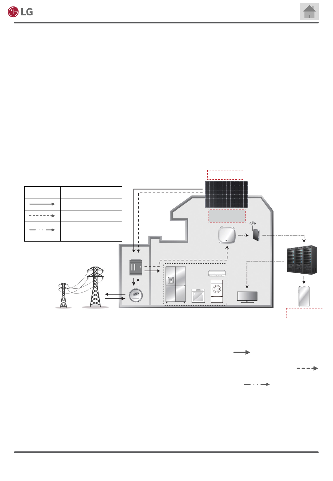
AC Module System
1. AC Module
Indicator Flow
Power ow
PLC signal
Wireless
communication
2. Communication
Gateway
3. Monitoring App
In this diagram, AC modules will produce power during daytime. The produced energy can be consumed
by home appliances like a fridge, TVs, etc. If the power generation is more than total power consumption
in the house, the power should ow to the grid. Power ow is described as .
The EnerBox2 utilizes power line communication (PLC) to collect data from each AC module. The PLC
matters for communication between microinverters and a EnerBox2. The PLC signal is depicted as .
The EnerBox2 sends data to the web server through a home router. Internet connection of the EnerBox2
is possible with Wi-Fi or a LAN cable. Wireless communication is described as .
Rev. 1.0
Copyright © 2020 LG Electronics.
All Rights Reserved.
10

Electronics
AC Module System Installation Manual
3 Installation
3-1 Instructions before Installation
• LG AC module is a “Grid Support Utility Interactive Inverter”, which requires approval from the
corresponding authority prior to connection with the utility grid. Contact the applicable local
government agencies and/or utility company.
• Installation, maintenance, and supervision may only be carried out by a qualied and authorized
installer to ensure the safety of workers and systems.
• Read and follow the installation guidelines specied in this manual. Installation with unapproved
methods may result in injuries including fatal injuries and/or damage to the equipment.
• If it is necessary to use an installation method which is not specied in the installation manual,
please contact LG Electronics. Failure to comply may void the warranty and the module certicate.
• After arrival of AC modules, check for possible damage during transportation. Damaged modules
should not be installed. Request an exchange by contacting LG Electronics.
• Secure all necessary permits and licenses to install the solar modules.
• Store the AC modules in original packing before installation.
• Keep the AC modules in a clear and secured area. Any particles or moisture may cause malfunction
of AC cable’s contactors.
• Consider the weight of AC module before installation.
• Do not work alone. Install AC modules with a team of at least 2 persons for safe installation.
• To prevent the risk of accidents, use proper PPE (Personal Protective Equipment) including
helmets and gloves at all times.
• If installation location is high above ground, make sure to use Fall Protection System during the
installation.
• Plan the installation work in moderate weather. There is a risk of electric shock when it is raining
or snowing.
• Partial shadowing may substantially reduce energy production.
• Check whether all parts used for the installation are certied for outdoor usage.
• Keep the solar module and system away from children at all times.
• During the AC module installation, do not let children play near the module and the system.
• Care must be taken to avoid low tilt angles which may cause dirt to buildup on the glass. A buildup
of dirt may cause performance degradation.
• Dirt build-up on the surface of the panel may cause active solar cells to be shaded and electrical
performance to be impaired.
• Carry out the installation according to the local electric code.
Rev. 1.0
Copyright © 2020 LG Electronics.
All Rights Reserved.
11
Electronics
AC Module System Installation Manual
3-2 Checking the Installation Site
Check whether the target site of installation meets the following requirements:
• Do not install AC modules near highly combustible structures or materials.
• Do not install AC modules where the maximum ambient temperature exceeds 65°C (149°F).
• Do not install AC modules at a place under direct exposure to salt water or ammonia.
• Do not install AC modules at a place easily accessible to people.
• Do not install AC modules indoors or on a moving vehicle.
In an environment having frequent lightning storms, an auxiliary grounding may need to be established
by the installer, which is connected directly from the AC module system to the ground.
If the target installation structure lies on an uneven surface, do not forcefully modify the module to
t in the structure. Make sure that the installation structure has been set up to provide a at surface.
Unreliable structures may cause damage to the product during and/or after installation.
Rev. 1.0
Copyright © 2020 LG Electronics.
All Rights Reserved.
12
Electronics
AC Module System Installation Manual
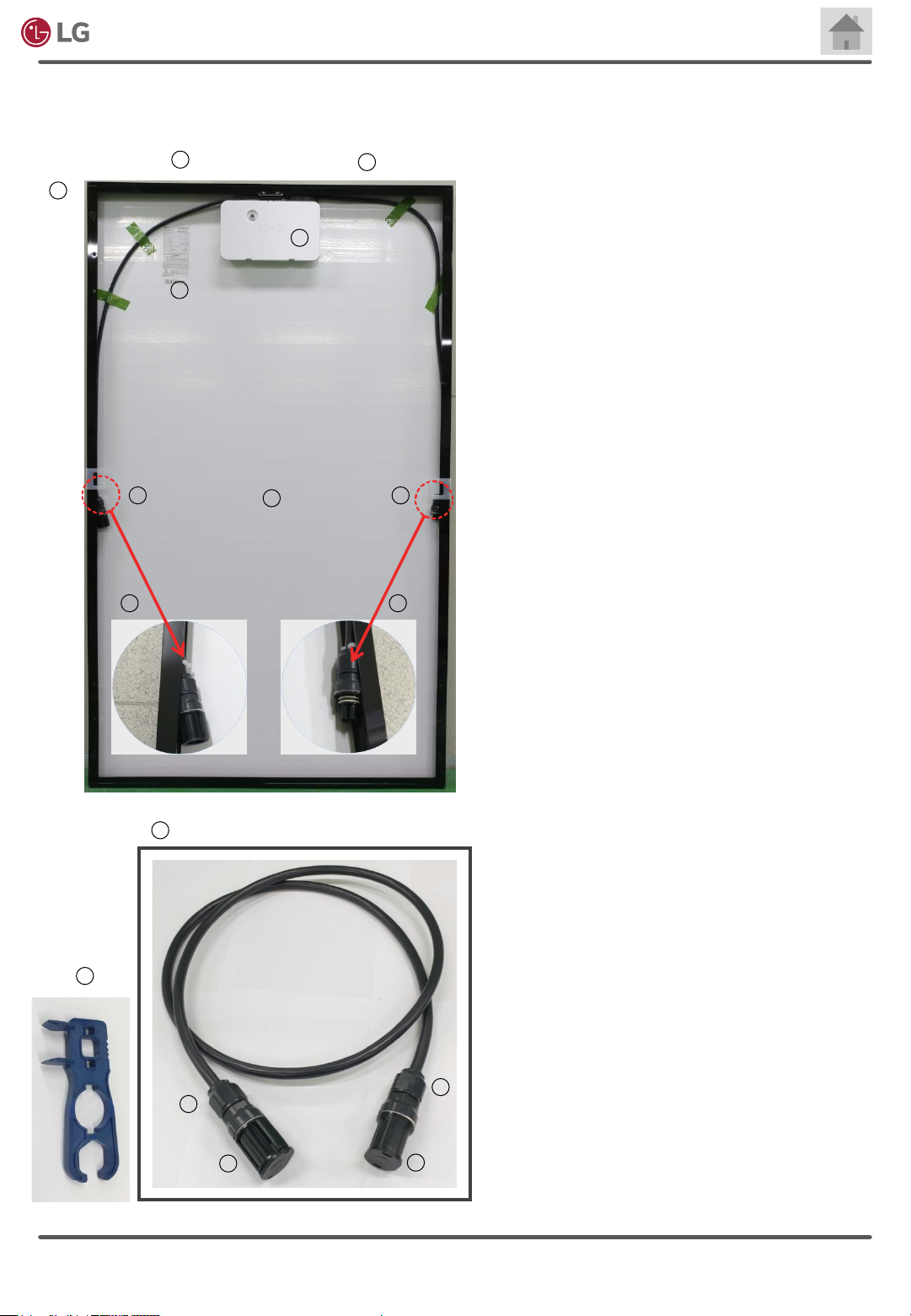
3-3 Inspecting Components of an AC Module
After receiving products, inspect all parts for possible deformity or malfunction.
9
3
10
AC Module
1. DC Module
converts the solar energy to DC power.
2
2. Microinverter
converts DC power generated by each PV
8
module to AC power
.
3. AC module frame
is a structural system to protect and support a
DC module and a microinverter.
4. AC Cable Male Connector
can be connected with an AC cable female
connector or a female end cap.
5. AC Cable Female Connector
can be connected with an AC cable male
1
45
connector or a male end cap.
6. AC Cable Male Connector Holder
holds the cable preventing it from getting free.
7. AC Cable Female Connector Holder
7 6
holds the cable preventing it from getting free.
8. Product Label
indicates product specication and MAC ID number.
9. Detachable MAC ID
is for a customer to place it on a map for record.
10. Model number
represents its model number.
16
Rev. 1.0
Accessory
11
13
12
14
15
Copyright © 2020 LG Electronics.
All Rights Reserved.
(Contact distributor to order)
11. Extension Cable (serviceable as a transition cable)
has both female/male connectors paired with
male/female end cap.
12. Male Connector
can be used for connection with a female
connector or a female end cap.
13. Female Connector
can be used for connection with a male
connector or a male end cap.
14. Female End Cap
is for sealing a male connector.
15. Male End Cap
is for sealing a female connector.
16. Unlocking Tool
for handling male and female connectors.
13
Electronics
AC Module System Installation Manual
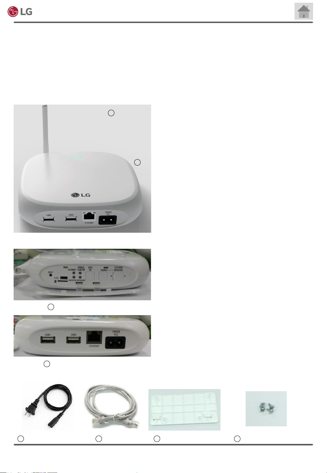
3-4 Inspecting Components of EnerBox2
After completing the installation of AC module on the rooftop or other site, next step is to install
the communication gateway (EnerBox2) which enables homeowners and installers to monitor
power production of individual AC module or the entire array on a daily, monthly or annual basis. The
communication system is simple to connect the gateway with each microinverter and an internet router.
Power Line Communication (PLC) method facilitates communication between the gateway and each
microinverter, then the gateway collecting energy and performance data from the AC modules in real
time transmits the accumulated log data to a web server through an internet router.
Wi-Fi Antenna
EnerBox2
2
EnerBox2 (Gateway)
(Contact distributor to order)
1. EnerBox2
is to collect energy harvest volume data from
installed AC modules.
1
2. Wi-Fi antenna
is attached on the body of EnerBox2 for wireless
connection of an EnerBox2 to a homeowner’s
existing router. A router is not provided by LG
Electronics.
3. EnerBox2 left-side
provides many functions including reset, buttons,
LEDs, etc.
4. EnerBox2 bottom-side
provides slots for power cable, LAN cable and
USBs.
5. EnerBox2 power cable
is used to provide power to EnerBox2 for
operation.
6. Lan Cable
3
EnerBox2 left-side
4
EnerBox2 bottom-side
5 8
EnerBox2 power cable Lan Cable Wall mount bracket
Rev. 1.0
Copyright © 2020 LG Electronics.
76
to connect the router in case wireless service is
not provided by a router.
7. Wall mount bracket
can be used for the EnerBox2 to be installed on
a wall.
8. Wall mount bracket screws
hold the wall mount bracket on a wall.
All Rights Reserved.
Wall mount bracket screws
14
Electronics
AC Module System Installation Manual
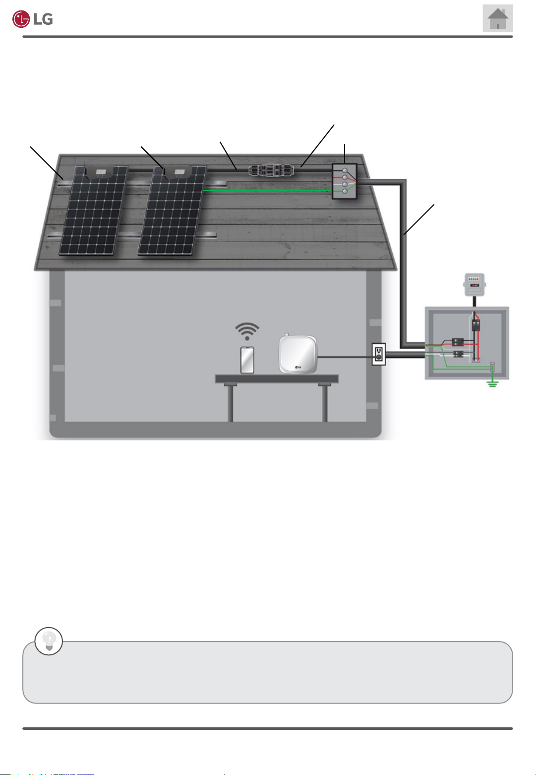
3-5 Wiring Diagram of AC Module System
Below is a sample diagram of the AC module system.
Transition Cable (transformed
from an extension cable)
PV Rack
AC Module
AC Cable
Equipment
Grounding
Conductor
EnerBox2
AC Junction Box
General AC Wiriing
Meter
2-pole
20A
N L1 L2
Distribution panel
G
1. AC module
- Consists of a DC module and a microinverter.
- Performs power conversion from solar power to AC Power and maximizes power generation by performing
MPPT (Maximum Power Point Tracking).
2. EnerBox2 (Communication Gateway)
- Collects data from the installed AC module system via AC cable.
- Uses wireless connection to transmit data to a server.
3. Monitoring App
- Monitors how much power is produced by the AC module system.
- Transmits the condition of the system to the service center in case of a problem.
• PV rack: Structure used to attach AC modules on surfaces like roofs, empty plots, etc.
• AC junction box: Container for electrical connections of AC wiring.
• Distribution panel: Component of an electricity supply system which divides an electrical power feed into
subsidiary circuits, while providing a protective fuse or circuit breaker for each circuit, in a common enclosure.
Rev. 1.0
Copyright © 2020 LG Electronics.
All Rights Reserved.
15

Electronics
AC Module System Installation Manual
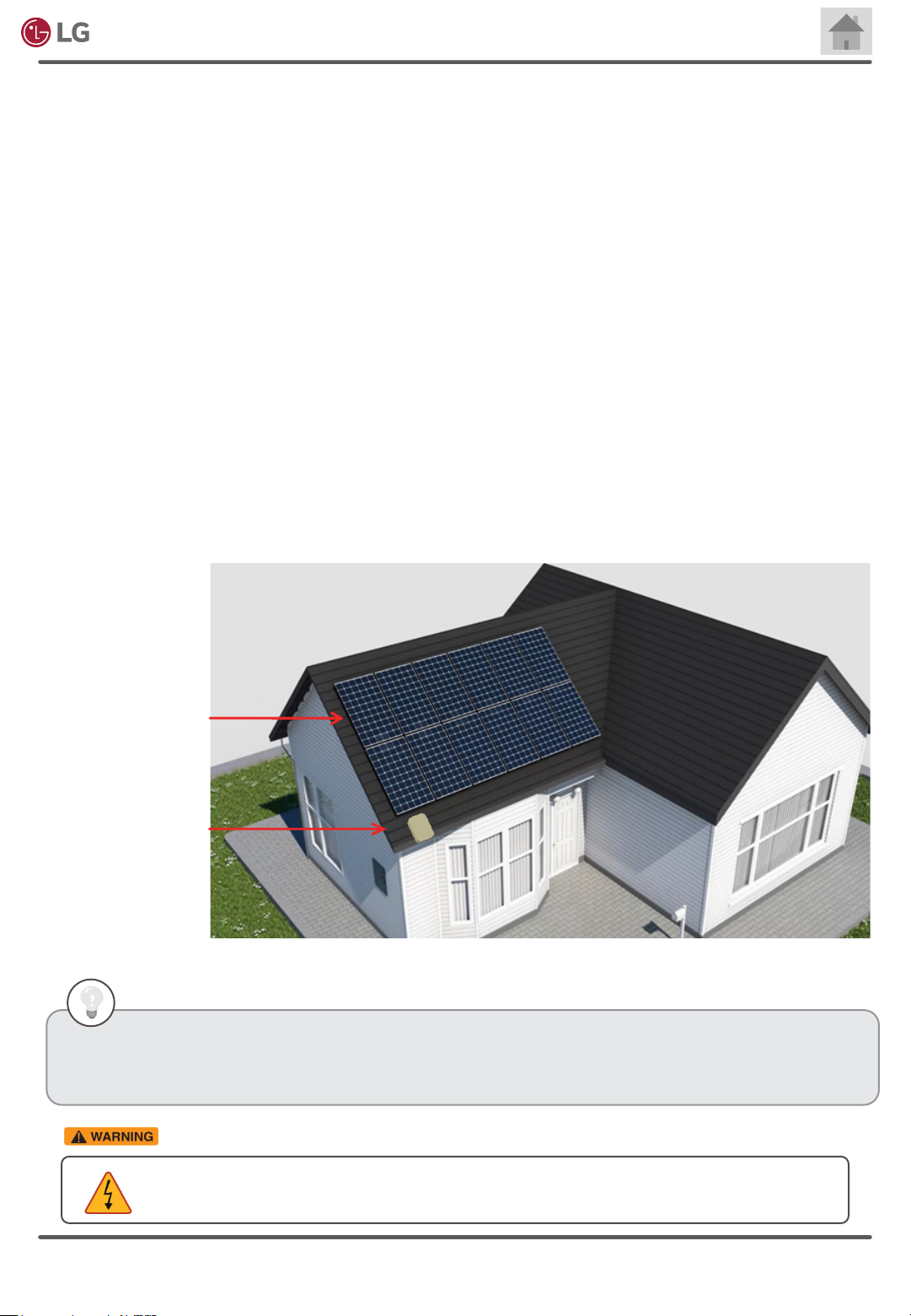
3-6 Installing the AC Junction Box and PV Rack
Before Installing the AC junction box and PV rack, be aware of the following requirements:
• Determine appropriate solar panel angle maximizing the amount of sunlight. This depends on
geographical conditions.
• To make better air circulation along the backside of the AC module, it is recommended to install the
PV rack with a gap of at least 4 inches (100mm) between the back of the module and roof surface. It
might affect UL listing and re class if it is less than 4 inches (100mm).
• Install AC junction box near the AC module.
• Install using the parts approved in the installation region.
Construct the overall frame of the solar system in the following order:
• Install the PV rack according to the number of modules per array and the dimensions of the AC
module. (refer to Chapter 9. Product Specication)
• Inspect the installation site and design possible combination of arrays that ts into the installation
site. If there are any vents or obstacles that make array build difcult, go to 3-9 Building an array of
AC modules to get ideas to design an array.
• Install the AC junction box near the PV rack. Select the size and type of AC junction box suitable for
connection type according to the output voltage. (refer to 3-12 Connecting Array of AC Modules-
to-Distribution Panel)
• Make sure that the AC junction box is protected by weatherproong materials or substances.
• Please use appropriate conduit or ducts for wires.
PV Racks
AC Junction Box
All procedures should be carried out by qualied installers. LG Electronics does not provide
or cover warranties for PV racks and the AC junction box.
PV module specication (conditions of 1000W/m2 irradiance and 25°C (77°F) solar cell temperature)
Operation temperature
Maximum operation temperature: 65°C (149°F).
Minimum operation temperature: -40°C (-40°F).
Design strength
Refer to Appendix 2 – Module Installation & Load Guide
Notes
-LG AC module should not be operated in locations where direct contact to salt water or ammonia exists.
Rev. 1.0
Copyright © 2020 LG Electronics.
All Rights Reserved.
16
Electronics
AC Module System Installation Manual
3-7 Mounting the AC module
Before mounting AC module in the PV rack, be aware of the following requirements:
• Check that all parts of the product are intact and operational.
• Check that the cable connectors are not damaged.
• Do not install the AC modules horizontally. It will make it difcult for dust to be washed off by rain naturally.
Accumulation of dust, dirt or soil may be a cause of performance degradation.
• When installed on a roof, the PV module must be mounted over a re-resistant roof. The re resistance of the PV
module is class C according to ANSI/UL790.
• For proper operation, do not remove AC module frame or replace with another frame.
• Do not make extra holes on the AC module frame. Additional holes on the frame may weaken the strength of the
frame and cause damage.
• To avoid the tensile strain from the thermal expansion, it is recommended to leave a space more than 6mm
(0.236 inches) between AC modules frames.
• Mount LG AC module to PV rack with 4~5N•m torque.
• For reliable connection, make sure that the AC module frame and a PV rack are surely fastened enough to prevent
the AC modules from getting loose.
• When installing modules in areas of heavy snow, special care should be taken to install the modules in a manner that
provides sufcient strength for meeting local code requirements.
AC Modules
AC Junction Box
Guides for mounting AC modules on the PV racks are explained on the following pages.
• When an AC module is exposed to light, it supplies a DC voltage to a microinverter. Therefore, the
LED on the microinverter will illuminate in red if it is not connected to the grid.
• To prevent the danger of electric shock, do not touch metal parts inside the AC cable connectors.
Rev. 1.0
Copyright © 2020 LG Electronics.
All Rights Reserved.
17
Electronics
AC Module System Installation Manual
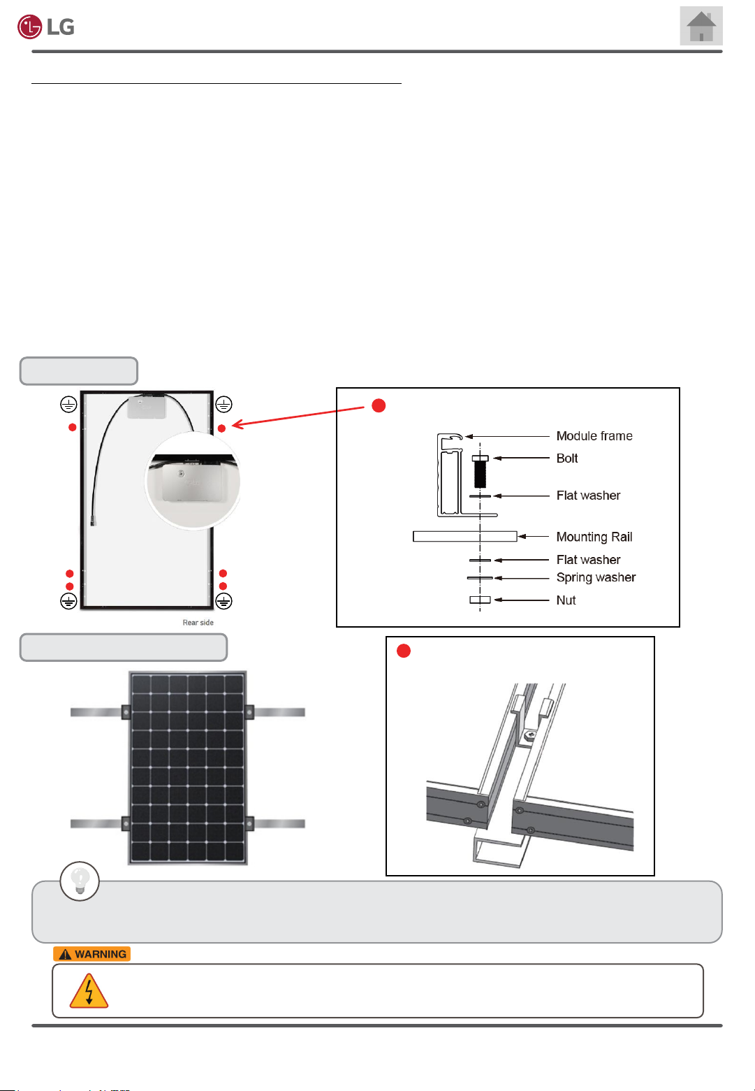
Mount AC module to the PV rack in the following order:
• Bolting type uses manufactured holes on the AC module frames to attach the AC modules on PV rack or support
structure. Use at least 4 mounting holes (2 on right and 2 on left frame) to securely hold the AC modules on the
structure. This mounting type is tested by a Nationally-Recognized Testing Laboratory.
• The AC module can be mounted by using clamps or xing plates. Steps and procedures need to be carried out based
on a manual provided by the clamp or xing plate manufacturers. The type is evaluated by LG internal test, not tested
by a Nationally-Recognized Testing Laboratory.
• Bolts, clamps or xing plates must be installed according to the manufacturer’s specic instructions.
• Do not apply too much pressure on the AC module frame to a degree that the frame deforms.
• Please follow instructions and manuals specied by bolt, clamp or xing plate manufacturers.
• Make sure that any clamps or xing plates do not contact the front glass and do not deform the frame. Also, be sure
to avoid shadowing effects caused by the clamps or xing plates.
• It is recommended to check with local authorities for re safety guidelines and requirements for any buildings or
structures onto which the panels will be installed.
Bolting type
Connection of the PV Rack and AC module
Clamp or fixing plate type
• Bolting Type is tested by a Nationally-Recognized Testing Laboratory. Refer to Appendix 2.
• Clamp or xing plate type is not tested by a Nationally-Recognized Testing Laboratory. The type is
evaluated by LG internal test.
• To prevent the danger of electric shock, do not attach or connect AC modules to the grid before the
installation.
• The actual grid connection should be done after all installation procedures are completed.
AC module frame clamps for an example
Rev. 1.0
Copyright © 2020 LG Electronics.
All Rights Reserved.
18
Electronics
AC Module System Installation Manual
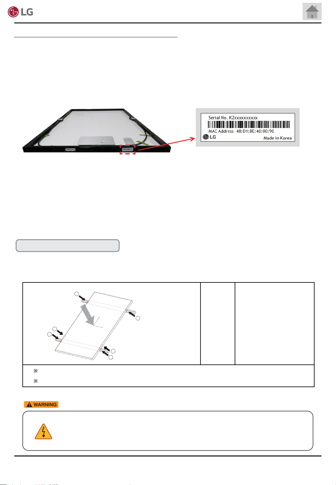
Mount AC module to the PV rack in the following order:
• Place AC modules on the PV rack with a minimum gap of 6mm (0.236 inches) between each module. To prevent the
risk of slipping during installation, mount AC modules one by one.
• Peel the adhesive label attached on the side of AC module frame and attach the identication label on LG AC module
Installation map. The map makes it easy for customers to identify the physical location of a particular AC module.
Each AC module has two MAC ID labels. One is placed under the product specication label. And the other is the
detachable MAC ID label.
• The layout of the array will be utilized for building a monitoring system allowing a customer to check the amount of
energy harvested.
• The AC modules can be mounted in landscape or portrait orientation, as illustrated below.
• When the AC module is mounted on a PV rack rail, ensure that the rail is inside the range specied in Appendix 2 –
Module Installation & Load Guide. The range varies depending on mounting methods.
• Appendix 2 guides you how to place PV rack rails and clamps in connection with AC modules.
Design Strength (Basic Load)
• 60Cell Modules: 75lb/ft2
• Detail of mounting distance is below.
2
2
2
1
2
1
This mounting method uses frame bolt holes.
Please refer to Appendix 2 –Module Installation & Load Guide.
• To prevent the risk of accidents, use proper PPE (Personal Protective Equipment) including
helmets and gloves at all times.
• If installation location is high above ground, make sure to use Fall Protection System during
the installation.
60 cell
① : 200mm (7.9 in)
② : 300mm (11.8 in)
Rev. 1.0
Copyright © 2020 LG Electronics.
All Rights Reserved.
19

Electronics
Portrait Orientation
AC Module System Installation Manual
270 mm
10.63 inch
400 mm
15.75 inch
270 mm
10.63 inch
400 mm
15.75 inch
Landscape Orientation
120 mm
4.72 inch
120 mm
4.72 inch
120 mm
4.72 inch
120 mm
4.72 inch
Rev. 1.0
• Check whether the male and female connectors between modules (except end cap and
junction box connection) are securely connected, then proceed to install next row of modules.
• All AC cable connectors must be installed underneath the module, out of rain and sun. Do not
leave AC cable connectors in an environment of long-term exposure to direct sunlight or rain.
Copyright © 2020 LG Electronics.
All Rights Reserved.
20
Electronics
• If the installation is likely to be affected by heavy (extreme) snow, further suitable panel support
is recommended on the lower row of panels.
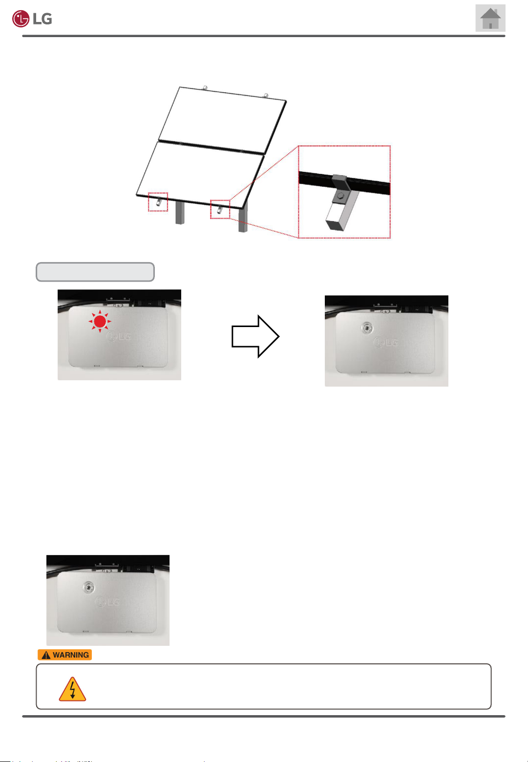
LED indicator
AC Module System Installation Manual
Flashing red light: Solar panel is
getting solar energy but it is not
providing power to utility grid.
• Connection time is set at 1min. After you turn the circuit breaker on for the actual utility
connection, the microinverter will be in operation to provide power to the grid.
• Reconnection time is set at 5 min. Reconnection time is applied if the microinverter is tripped
with grid voltage and frequency abnormality. For example, if the circuit breaker is turned
off during operation, the reconnection time of 5 min. will be applied. Once it starts power
production, connection of 1 min. will be applied.
• After connection time or reconnection time, the microinverter will transform DC power to AC
power for utility grid.
1. At night, the LED will have no light because there is no energy
to make the LED illuminate.
2. During daytime, the LED will blink ashing red when the PV
panel is getting solar energy but the microinverter is not
providing power to grid. However, there will be no red light if
it generates AC power to a utility grid.
• Ensure that the microinverters are not interfered by the PV racks or ventilation structures.
Do not allow any structure to put pressure on microinverters. Continuous stress or force
might cause of malfunction.
No red light: Solar panel is
getting solar energy and it is
providing power to utility grid.
Rev. 1.0
Copyright © 2020 LG Electronics.
All Rights Reserved.
21
Electronics
AC Module System Installation Manual
3-8 Coupling AC cable Connectors
Before pairing AC cable connectors, familiarize yourself with the following descriptions specically
explaining how to handle AC cable connectors and accessories.
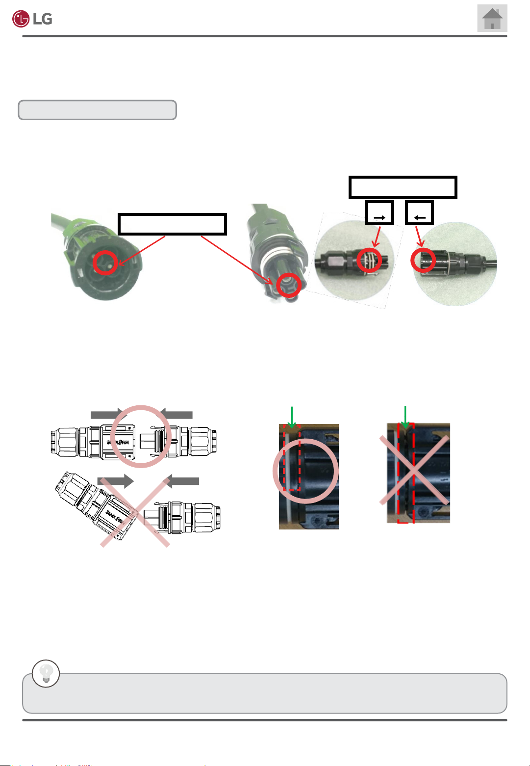
AC cable connector insertion
• AC cable connectors can be easily paired to connectors in the right direction.
• Before pairing two AC cable connectors, identify the locations of ‘Fool-proof system’ on each AC cable connector.
• Inserting the AC cable female connector into the AC cable male connector is only possible when ‘Fool-proof
System’ is properly matched.
• Use fool-proof system 1 or 2 as per your convenience.
Fool-proof System 2
M
F
Fool-proof System 1
• Insert the AC cable female connector into the AC cable male connector horizontally. If you insert at the wrong
angle, the connector can be damaged.
• When the temperature is warm and you are about to engage two connectors, you might not hear two clicks. In that
case, engage connectors until there is no space (no gap) between connectors.
• Insert the connector fully into the end of the other connector until you hear two clicks.
• When the connectors are correctly connected, there should be no space between the end of a male connector and
the end of a female connector.
No gap
A gap
• Do not let cable be pulled too tight or hang too loose. Internal conductor may break.
• Do not allow any liquid inside to prevent danger of electric shock.
• Do not use damaged cables.
• Do not cut or transform AC cables for use.
• Frequent disassembly or connection may damage connectors.
• The size of the cables are in accordance with NEC2014. (For the size, refer to Chapter 9. Product Specication)
• For information about accessories, refer to Chapter 8. Accessories.
• AC cable information can be found in Chapter 8 AC Module Accessories.
Rev. 1.0
Copyright © 2020 LG Electronics.
All Rights Reserved.
22

Electronics
• Do not bend the cable too many times. It may result in mechanical and/or electrical problems.
• Do not disconnect AC cable connectors under load.
• Use the dedicated unlocking tool to remove the connector. Do not use any other tools.
• The unlocking tool is specically made for disconnecting the two AC cable connectors.
• The male and female connectors will be opened by fully depressing the unlocking tool into the latches.
• After the unlocking tool insertion is complete, pull the connectors apart.
AC Module System Installation Manual
AC Cable Connector removal
Pull
• Avoid any external equipment interfering with the connector.
• Do not impose force on the side of the connector.
• Do not apply too much force pulling AC cables away from the connectors or the microinverter.
• The cable must not be bent, crushed or pinched where the cable connects to screw joint.
• The cable must be routed in a way that tensile stress on the conductor or connections is prevented.
• A minimum bending radius of 55mm must be maintained.
Unlocking Tool
R
• Do not attempt to assemble connectors in wet, soiled, or dusty environment.
• Keep connectors dry and clean, and ensure that connectors have no damage or deformities.
• Avoid connectors resting on the ground or roof surface. AC cables should be kept away from the ground or roof
surface. Use proper tools like cable clips for securely attaching AC cables on structures like PV racks.
• Avoid sunlight exposure and water immersion of the connectors.
• Incomplete connections can result in arcs and electrical shock.
• Check that all AC cables are securely fastened to structures.
• Ensure that all locking connectors are fully engaged and locked.
• Do not leave unconnected (unprotected) connectors exposed to the environment. Use appropriate end caps for the
unconnected AC cable connectors.
• To prevent the danger of electric shock, make sure to turn off the circuit breaker before the installation.
• Do not disconnect AC cable connectors under load.
Rev. 1.0
Copyright © 2020 LG Electronics.
All Rights Reserved.
23
Electronics
AC Module System Installation Manual
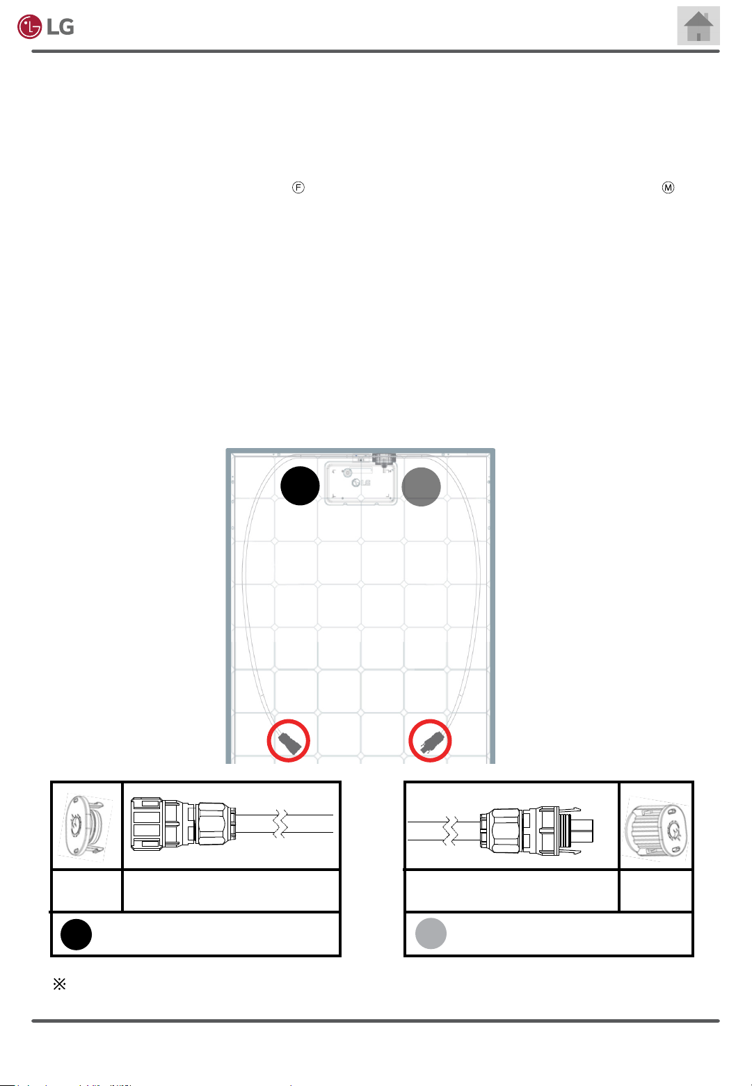
3-9 Building an Array of AC modules
• Remove the tape securing the AC cables and connectors to the back of the module.
• Each AC module has an AC cable male connector and an AC cable female connector.
• AC cable female connector is located on the left at rear side, or the right at front side.
• AC cable male connector is placed on the right at rear side, or left at front side.
• For easy recognition of the position, the below represents the location of the female connector and the stands
for the location of the male connector.
• Because male connector is designed to be connected with a female connector or female end cap, there is a need to
keep track of the positions of male and female connectors when you build an array.
• The AC module produced by LG Electronics is delivered with the microinverter pre-installed on the DC module.
• Therefore, it eliminates installation steps for pairing DC module outputs and microinverter inputs.
• The length of the AC cables are designed to enable easy cable links throughout an array you have designed.
• Landscape, portrait or a combination of both is possible with the AC cable connectors.
• Even if there are roof vents on the target site, AC cable connection is feasible for the AC module array to circumvent
the vent area.
Male
End Cap
F
AC Cable Female Connector
M
AC Cable Male Connector
Female
End Cap
F
Rev. 1.0
Position of the female connector
The end caps are not attached on the above AC cable connectors. Male or female end caps are
provided with extension cables. This diagram is for showing that each end cap has its pair.
Copyright © 2020 LG Electronics.
Position of the male connector
M
24
All Rights Reserved.

Electronics
• Do not expose the cable connections to directed, pressurized liquid (water jets, etc.).
• Do not expose the cable connections to continuous immersion.
• Do not expose the AC cable connector to continuous tension.
• Use only the connectors and cables provided by LG Electronics.
• Do not allow contamination or debris inside the connectors.
• Use cables and connectors only when all parts are present and intact.
• All AC cable connectors must be installed underneath the module, out of rain and sun. Do not leave AC cable
connectors in an environment of long-term exposure to direct sunlight or rain.
• Ensure that the microinverters are not interfered by the PV racks, ventilation structures. Do not allow any structure to
put pressure on microinverters. Continuous stress or force may cause malfunction.
• Attach the AC Cable to the PV racks using the cable clips. Keep the AC cables away from the ground surface or the
ro o f.
• After checking whether pairing male and female connectors between modules (except end cap and junction box
connection) are securely connected, proceed to install next row of modules.
• Seal the last AC cable connector with an appropriate end cap to add the waterproof function. Insert the end cap into
the male or female connector in the arrow direction until you hear a click sound or nd no gap at the edge. (Refer to
the 3-8 Coupling AC cable connectors). End caps are attached on each extension cable that you have ordered.
AC Module System Installation Manual
Rev. 1.0
-AC cable connector and end cap include waterproof functions.
• Make sure to use AC cables, extension cables and end caps provided by LG. If cables other than genuine are
used, waterproong may not be guaranteed and the permissible current of the cable may be lower than the
output current of the microinverter.
• To prevent the danger of electric shock, rmly connect all connectors and end caps.
Copyright © 2020 LG Electronics.
All Rights Reserved.
25

Electronics
AC Module System Installation Manual
3-10 Building Blocks of an Array
6 Building Blocks
Male connector
Female connector
• There are 6 building blocks of AC modules which can be used in building an array. Using the 6
building blocks helps installers sketch array conguration and plan the AC cable connection. The
designer needs to keep in mind that the location of female and male connectors will affect array
design.
• Each building block has a limitation on the space between two AC modules because of cable
length. Therefore, the space gap between two AC module frames must be kept under the value
specied in each building block.
• Also, to avoid tensile strain from thermal expansion, it is recommended to leave a space more
than 6 mm (0.236 inches) between AC module frames.
• This manual provides gap limitation between AC module frames for each building block. After
male and female connection of two AC modules, use cable clips in order to fasten the AC cables
on frames or PV racks.
• Keep the AC cables off the roof surface or ground.
• In brief, simple diagrams indicate different types of building blocks describing location of male
and female connectors and gap limitation between AC module frames. So do not interpret the
simple diagrams as the AC cables must make path only to the top direction from an AC module.
• In cases of portrait in reverse and landscape in common, AC cables run below the microinverter
to meet another AC cable. Keep in mind to fasten the AC cables on frames or PV racks in order
to keep them off of the roof surface.
Portrait in common
Portrait in reverse
Landscape in common
<300mm
<11.81 inch
<50mm
<1.95 inch
<50mm
<1.95 inch
<1000mm
<39.37 inch
<50mm
<1.95 inch
<50mm
<1.95 inch
Rev. 1.0
Copyright © 2020 LG Electronics.
All Rights Reserved.
26

Electronics
Fastening AC cables on PV racks or AC module frames
• Use cable clips in order to fasten the AC cables on AC module frames or PV racks.
• Keep the AC cables off of roof surface or ground.
• For cases of portrait in reverse or landscape in common, steps are described to recommend to
fasten AC cables on AC module frames and PV racks.
For portrait in reverse or landscape in common:
A. Get the AC cable paired.
B. Use a mounting hole with a cable clip for fastening the AC cable on the AC module frame.
Mounting holes are placed in red dots as displayed in the rear side of an AC module.
C. Attach another AC cable on near PV racks.
AC Module System Installation Manual
Location of mounting hole
Location of grounding hole
Mounting holes can be used for cable clip
B
A
C
Portrait in reverse
Cable Management Clip
C
A
B
Landscape in common
Rev. 1.0
Copyright © 2020 LG Electronics.
All Rights Reserved.
27
Electronics
AC Module System Installation Manual
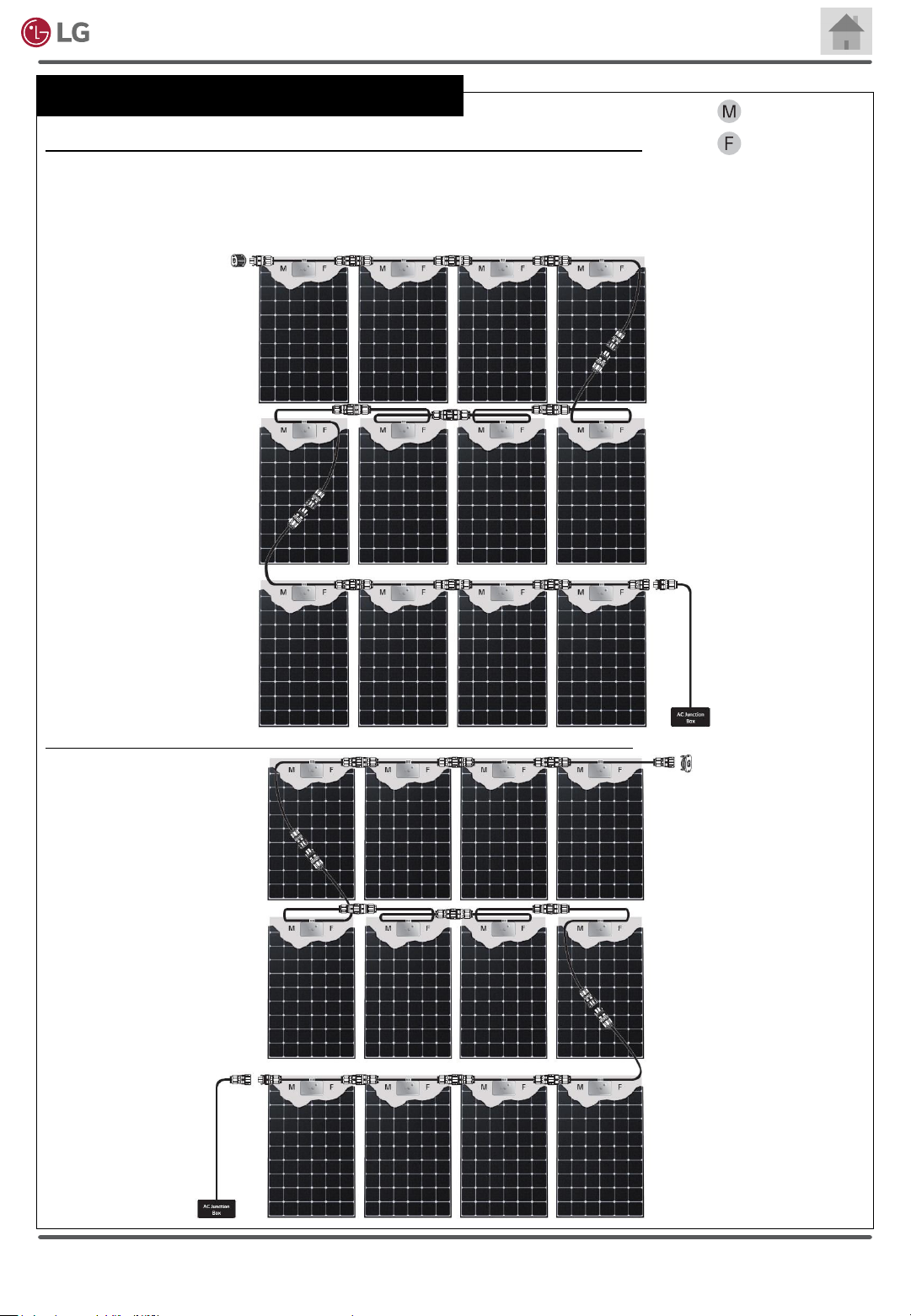
Possible combination of AC modules for array design
If AC junction box is on the right side of a 3-by-4 PV array in portrait orientation,
Use proper transition cable for connecting the array with the AC junction box. (Refer to 3-12 Connecting Array of AC
Modules-to-Distribution Panel guiding installers to make a transition cable from an extension cable) Seal the AC cable
male or female connectors of the last AC module using an appropriate end cap. End caps can be found in an extension
cable
.
Male connector
Female connector
If AC junction box is on the left side of a 3-by-4 PV array in portrait orientation,
Rev. 1.0
Copyright © 2020 LG Electronics.
All Rights Reserved.
28

Electronics
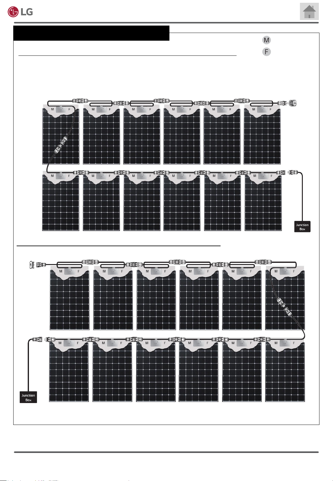
Possible combination of AC modules for array design
AC Module System Installation Manual
Male connector
If AC junction box is on the right side of a 3-by-4 PV array in landscape orientation,
Use proper transition cable for connecting the array with AC junction box. (Refer to 3-12 Connecting Array of AC
Modules-to-Distribution Panel guiding installers to make a transition cable from an extension cable) Seal the AC cable
male or female connector of the last AC module using an appropriate end cap. End caps can be found in an extension cable.
Female connector
If AC junction box is on the left of a 3-by-4 PV array in landscape orientation,
Requirement for the landscape formation.
Unlike a connection in a portrait orientation, two AC modules in a landscape orientaion must be placed with a gap of at
least 6mm (0.24 inch) and no more than 50mm (1.95 inch). Otherwise, the length of the AC cables is not enough for
male and female connectors to be fully connected.
<50mm
<1.95 inch
Rev. 1.0
<50mm
<1.95 inch
Copyright © 2020 LG Electronics.
All Rights Reserved.
29
Electronics
Possible combination of AC modules for array design
AC Module System Installation Manual
Male connector
If AC junction box is on the right side of a 2-by-6 PV array in portrait orientation,
Use proper transition cable for connecting the array with AC junction box. (Refer to 3-12 Connecting Array of AC
Modules-to-Distribution Panel guiding installers to make a transition cable from an extension cable) Seal the AC cable
male or female connector of the last AC module using an appropriate end cap. End caps can be found in an extension
cable.
Female connector
If AC junction box is on the left of a 2-by-6 PV array in portrait orientation,
Rev. 1.0
Copyright © 2020 LG Electronics.
All Rights Reserved.
30
 Loading...