

Page 1

OWNER’S MANUAL
Hybrid Digital Video
Recorder
Please read this manual carefully before operating
your set and retain it for future reference.
MODELS
LE5016/LE5008 Series
LE4016/LE4008 Series
P/NO : MFL60560470 1012 (V1.1)
Page 2
Safety Information
2
1
1
Safety Information
Safety Information
CAUTION
RISK OF ELECTRIC SHOCK
DO NOT OPEN
CAUTION: TO REDUCE THE RISK OF ELECTRIC SHOCK
DO NOT REMOVE COVER (OR BACK)
NO USER-SERVICEABLE PARTS INSIDE
REFER SERVICING TO QUALIFIED SERVICE PERSONNEL.
This lightning ash with arrowhead symbol within an
equilateral triangle is intended to alert the user to the
presence of uninsulated dangerous voltage within the
product’s enclosure that may be of sucient magnitude
to constitute a risk of electric shock to persons.
The exclamation point within an equilateral triangle is
intended to alert the user to the presence of important
operating and maintenance (servicing) instructions in
the literature accompanying the product.
FCC WARNING: This equipment may generate or use radio
frequency energy. Changes or modications to this equipment may
cause harmful interference unless the modications are expressly
approved in the instruction manual. The user could lose the
authority to operate this equipment if an unauthorized change or
modication is made.
REGULATORY INFORMATION: FCC Part 15
This equipment has been tested and found to comply with the
limits for a Class A digital device, pursuant to Part 15 of the FCC
Rules. These limits are designed to provide reasonable protection
against harmful interference when the equipment is operated in a
commercial environment.
This equipment generates, uses, and can radiate radio frequency
energy and, if not installed and used in accordance with the
instruction manual, may cause harmful interference to radio
communications.
Operation of this equipment in a residential area is likely to cause
harmful interference in which case the user will be required to
correct the interference at his own expense.
• A suitable conduit entries, knock-outs or glands shall be
provided in the cable entries of this product in the end user.
• Caution: Danger of explosion if battery is incorrectly replaced.
Replaced only with the same or equivalent type recommended
by the manufacturer. Dispose of used batteries according to the
manufacturer’s instructions.
• Holes in metal, through which insulated wires pass, shall
have smooth well rounded surfaces or shall be provided with
brushings.
This Class A digital apparatus complies with Canadian ICES-003.
Cet appareil numérique de la classe A est conforme à la norme
NMB-003 du Canada.
Warning: Do not install this equipment in a conned space such as
a bookcase or similar unit.
Warning: Wiring methods shall be in accordance with the National
Electric Code, ANSI/NFPA 70.
Warning: This is a class A product. In a domestic environment this
product may cause radio interference in which case the user may
be required to take adequate measures.
Warning: To reduce a risk of re or electric shock, do not expose
this product to rain or moisture.
Caution: This installation should be made by a qualied service
person and should conform to all local codes.
Caution: To avoid electrical shock, do not open the cabinet. Refer
servicing to qualied personnel only.
Caution: The apparatus should not be exposed to water (dripping
or splashing) and no objects lled with liquids, such as vases, should
be placed on the apparatus.
Caution:
This product employs a Laser System. To ensure proper use of this
product, please read this owner’s manual carefully and retain it
for future reference. Should the unit require maintenance, contact
an authorized service center. Performing controls, adjustments,
or carrying out procedures other than those specied herein may
result in hazardous radiation exposure. To prevent direct exposure to
laser beam, do not try to open the enclosure. Visible laser radiation
when open. DO NOT STARE INTO BEAM.
To disconnect power from mains, pull out the mains cord plug.
When installing the product, ensure that the plug is easily
accessible.
Page 3

Safety Information
3
LG Electronics hereby declares that this/these
product(s) is/are in compliance with the essential
requirements and other relevant provisions of
Directive 2004/108/EC, 2006/95/EC, and 2009/125/
EC.
European representative :
LG Electronics Service Europe B.V. Veluwezoom 15,
1327
AE Almere. The Netherlands
(Tel : +31-(0)36-547-8888)
Disposal of your old appliance
1. When this crossed-out wheeled bin symbol is
attached to a product it means the product is
covered by the European Directive 2002/96/EC.
2. All electrical and electronic products should
be disposed of separately from the municipal
waste stream via designated collection facilities
appointed by the government or the local
authorities.
3. The correct disposal of your old appliance will help
prevent potential negative consequences for the
environment and human health.
4. For more detailed information about disposal of
your old appliance, please contact your city oce,
waste disposal service or the shop where you
purchased the product.
EEE Compliance with Directive. (for Turkey only)
Safety way to remove the battery or the battery from the
equipment:
Remove the old battery or battery pack, follow the steps in
reverse order than the assembly. To prevent contamination of the
environment and bring on possible threat to human and animal
health, the old battery or the battery put it in the appropriate
container at designated collection points. Do not dispose of
batteries or battery together with other waste. It is recommended
that you use local, free reimbursement systems batteries and
accumulators. The battery shall not be exposed to excessive heat
such as sunshine, re or the lile.
IMPORTANT SAFETY INSTRUCTIONS
1
Safety Information
1. Read these instructions.
2. Keep these instructions.
3. Heed all warnings.
4. Follow all instructions.
5. Do not use this apparatus near water.
6. Clean only with dry cloth.
7. Do not block any ventilation openings. Install in accordance
with the manufacturer's instructions.
8. Do not install near any heat sources such as radiators, heat
registers, stoves, or other apparatus (including ampliers) that
produce heat.
9. Do not defeat the safety purpose of the polarized or groundingtype plug. A polarized plug has two blades with one wider
than the other. A grounding type plug has two blades and
a third grounding prong. The wide blade or the third prong
are provided for your safety. If the provided plug does not t
into your outlet, consult an electrician for replacement of the
obsolete outlet.
10. Protect the power cord from being walked on or pinched
particularly at plugs, convenience receptacles, and the point
where they exit from the apparatus.
11. Only use attachments/accessories specied by the
manufacturer.
12. Use only with the cart, stand, tripod, bracket, or table specied
by the manufacturer, or sold with the apparatus. When a
cart is used, use caution when moving the cart/apparatus
combination to avoid injury from tip-over.
13. Unplug this apparatus during lightning storms or when unused
for long periods of time.
14. Refer all servicing to qualied service personnel. Servicing is
required when the apparatus has been damaged in any way,
such as power-supply cord or plug is damaged, liquid has been
spilled or objects have fallen into the apparatus, the apparatus
has been exposed to rain or moisture, does not operate
normally, or has been dropped.
Page 4

Safety Information
4
Safety warnings and Cautions
1
The following are warnings and cautions for the safety of the users and for the prevention of any property damage. Please read the following
Safety Information
carefully.
WARNING
• Turn o the system before installation. Do not plug in several electric devices to the same outlet.
- This may cause heating, re, or electric shock.
• Do not place any liquid container on the system, such as water, coee, or other beverage.
- If liquid is poured onto the system, it can cause a system breakdown or re.
• Prevent the power cable from being severely bent or having pressure exerted on it by a heavy object.
- This may cause re.
• Clean the dust around the system on a regular basis. When cleaning the system, always use a dry cloth. Do not use a wet cloth or other
organic solvents.
- This may damage the surface of the system and can cause a system breakdown or electric shock.
• Avoid any place with moisture, dust, or soot.
- This can cause re or electric shock.
• When pulling the power cable from the plug, do so gently. Do not touch the plug with wet hands and avoid using the plug if the holes in
the outlet are too loose.
- This may cause re or electric shock.
• Do not attempt to disassemble, repair, or modify the system on your own. It is extremely dangerous due to the high voltage running
through the system.
- This may cause re, electric shock, or serious injury.
• Check for any danger signs such as a moist oor, a loosened or damaged power cable, or an unstable surface. If you encounter any
problems, ask your dealer for assistance.
- This may cause re or electric shock.
• Keep a distance of at least 15cm between the back of the system and the wall for the cables connected to the system otherwise, they may
be bent, damaged, or cut.
- This may cause re, electric shock, or injury.
• Install the system in a cool place without direct sunlight and always maintain room temperature. Avoid candlelight and heat generating
devices such as heaters. Keep the system away from places where many people pass.
- This may cause re.
• Install the system on a plain surface with sucient air ventilation. Do not place the system on an elevated surface.
- This may cause system breakdown or serious injury.
• The power outlet must be placed on the ground, and the voltage range must be within 10% of the voltage rate. Do not use the same
outlet with a hair dryer, iron, refrigerator, or any heating appliances.
- This may cause re, over heating or electric shock.
• When the system’s battery is depleted, replace it with the same or equivalent type of battery specied by the manufacturer. Depleted
batteries should be discarded according to the manufacturer’s instructions.
- This may cause an explosion.
• If the system’s HDD exceeds its life span, you may not be able to recover any data stored inside the HDD. If the video on the system screen
appears ‘damaged’ while playing a recording stored inside the system’s HDD, it must be replaced with a new one. Ask for an engineer’s
assistance for HDD replacement from your dealer.
- LG Electronics is not responsible for deleted data caused by user mishandling.
Page 5

Safety Information
CAUTION
Please beware of the following precautions before installing the DVR.
• Avoid positioning the product in any place where the unit may come into contact with moisture, dust, or soot.
• Avoid placing in direct sunlight or near heating appliances.
• Keep the product away from electric sparks or magnetic substances.
• Do not place any conductive material through the ventilation grills.
• Keep the system turned o before installation.
• Ensure enough space is left for cable connections.
• Place the system on a solid surface with sucient air ventilation. Avoid any surface that vibrates.
• Placing the system near electronic devices such as a radio or a TV may cause the product to breakdown.
• Do not disassemble the product without seeking assistance from LG Electronics.
• Do not place any heavy object on the system.
• Prevent any substances from being inserted into the system.
- This may cause system breakdown.
• Install the system in a place with sucient air ventilation.
- Keep at least 15cm distance between the back of the system and the wall, and at least 5cm distance between the side of the system
and the wall.
• Do not install the system in a place with high magnetic, electric wave, or wireless devices such as a radio or a TV.
- Do not install the system in a place with magnetic objects, electric frequencies, or vibration.
• Do not place any heavy object on the system.
- This may cause system breakdown.
• Install the system on a stable, level surface.
- The system may not operate properly.
• Install the system in a place with appropriate moisture and temperature levels.
- Avoid installing the system in a place with high (over 40°C) or low (under 0°C) temperature.
• The system can be damaged from a strong impact or vibration. Avoid throwing objects within the vicinity of the system.
• Avoid direct sunlight or any heating appliances.
- Recommended operating temperature is over 0°C (32°F).
• Ventilate the air inside the system operation room, and tighten the system cover rmly.
- System breakdown may be caused by an inappropriate environment. It is recommended to use AVR (Automatic Voltage Regulator)
for a stable power supply. It is recommended to coil the core-ferrite around the connector of the system to avoid electromagnetic
interference.
• The outlet must be placed on the ground.
• If there is strange sound or smell, unplug the power cable immediately and contact the service center.
- This may cause re or electric shock.
• In order to maintain stable system performance, have your system checked regularly by the service center.
- LG Electronics is not held responsible for system breakdown caused by user mishandling.
- There is a risk of explosion if a battery is replaced by an incorrect type. Dispose of used batteries according to the instructions.
• Do not overturn the product during use.
5
1
Safety Information
Page 6

Contents
6
Contents
1
1
2
Safety Information
3 IMPORTANT SAFETY INSTRUCTIONS
2
3
Preparation
8 Introduction
8 Features
4
8 Accessories
9 Front Panel
11 Rear Panel
12 Remote Control
5
3
Installation
6
13 Connections
13 Precautions
13 Basic Connection Overview
14 Connecting Camera
7
14 Connecting Display device
14 Connecting Audio device
15 Connecting USB device
15 Connecting ATM/POS
16 Connecting Network
16 Connecting RS-485 device
17 Connecting Alarm Input and Alarm Output
18 HDD INSTALLATION
18 Note for Hard Disk Drive
18 Installing the Hard Disk Drive
19 Replacing the Hard Disk Drive
19 Recommended HDD
19 System Operation
19 System Shutdown
20 General Explanation of the Live
Screen on the Main Monitor
20 Main Monitor Screen
21 Selecting the Main Monitor screen mode
22 Selecting the Spot Monitor screen mode
22 PTZ Camera Control
24 Viewing System Information
24 Viewing the System Log List
26 Configuration menu
27 System settings
27 Properties
27 Network
28 Network Streaming
28 DDNS
28 Date/Time
29 NTP
29 Controller
29 Update
30 Backup
31 Device settings
31 Camera
31 PTZ
32 IP Camera
32 ATM/POS
33 Storage
33 Display settings
33 OSD
33 Sequence
34 Channel Composition
34 Video Adjustment
34 Record settings
34 Schedule
34 To Set the Recording Schedule for a Typical
Day of the Week
36 Copying the Recording Schedule
36 Normal
36 Sensor
37 Motion
37 Text
37 Instant/Panic
38 IP camera
38 Event settings
38 Sensor
38 Motion
39 ATM/POS Data Format
39 Event Popup
39 Notification
40 Mail
40 Emergency
40 Output
41 Buzzer
41 User settings
41 Group Authority
4
Operation
43 Instant Recording
Page 7

Contents
7
43 Panic Recording
44 Instant Playback
44 Search and Playback
44 Date and Time Search
44 Event Search
45 Bookmark Search
45 ATM/POS Search
46 Export Search
47 Functions Available During Playback
5
LG Network Client Program
48 Introduction
48 Recommended PC Requirements
48 Before install the program
48 Getting Started
48 Install the LG Network Client on your PC
48 Starting the LG Network Client
49 LG Network Client Overview
51 Operation and settings
51 Register the Site Name or Group Name
51 Connect to the DVR
51 Connect the group device
52 Disconnect the site name or group name
52 Using the Live function
55 Using the Search function
56 Using the Remote Setup function
61 Using the Export function
62 Using the E-Map function
63 Additional Programs
63 Emergency Agent Program
64 Export Viewer Program
65 Web Viewer Program
78 Recording Time Table (250GB HDD)
81 Specifications
1
2
3
4
5
6
7
6
Troubleshooting
7
Appendix
69 Recommended Devices
69 Recommended USB Memory list
69 Recommended External Device list
69 Recommended CD/DVD Media list
70 Supported function list for device
70 Supported PTZ Camera list
71 Time zones
72 Factory Default Configuration Settings
Page 8

8
Preparation
2
Preparation
2
Preparation
Introduction
Model LE5016D (16 Channel) is used for the description, operation
and details provided in this operating guide.
Features
• Stable embedded Linux operating system.
• Journal ling system for HDD le recovery following power
recovery.
• Small le sizes with H.264 compression.
• Internal storage expandable to 4TB. (Expandable if new high
capacity HDD is launched)
• NTSC and PAL selectable video format.
• Full real-time recording.
Up to 480 IPS @ 704x480, LE5016 Series
NTSC
PAL
• Various recording resolutions and quality levels.
NTSC D1(704x480), Half D1(704x240), CIF(352x240)
PAL D1(704x576), Half D1(704x288), CIF(352x288)
Up to 240 IPS @ 704x480, LE5008 Series
Up to 480 IPS @ 352x240, LE4016 Series
Up to 240 IPS @ 352x240, LE4008 Series
Up to 400 IPS @ 704x576, LE5016 Series
Up to 200 IPS @ 704x576, LE5008 Series
Up to 400 IPS @ 352x288, LE4016 Series
Up to 200 IPS @ 352x288, LE4008 Series
• Automatic backup by schedule.
• Image authentication (Watermark).
• Three USB 2.0 ports for backup interface.
• Setup conguration export/import with USB memory stick.
• Easy system S/W update with USB memory stick.
• Clients S/W can manage max 100 DVR servers.
• Max ve clients can access one DVR server simultaneously.
• Network bandwidth throttle.
- Automatically adjust a bandwidth according to network
speed status of unit.
• Remote alarm notication via client software or E-mail.
• Time and date sync from NTP server.
• Daylight saving mode.
• Covert camera protection.
• Support Gigabit Ethernet.
• E-SATA storage interface.
• Two-way audio.
• Text Input for ATM and POS device.
• User management (User level control).
• PTZ Control.
- Dome camera telemetry control (Dome OSD control).
Accessories
Software
Install CD
Screws
- 5 step quality level (Highest, High, Standard, Low, Lowest).
• Easy operation using various user interface & user friendly GUI.
- Optical mouse, Full function IR remote controller
• Powerful multiplex function.
- Simultaneous live display, recording, playback, network
transmission, back-up.
• Various search function.
- Date/time search (calendar search), event search, bookmark
search.
• Event data protection by event partition recording.
• Pre-alarm recording (Up to 1 minute).
• Motion event recording and preview test function of motion
sensitivity.
• Recording image rate & quality adjustment per individual
camera.
• Powerful record scheduling.
• Instant playback in live mode.
• Perfect audio/video synchronization.
Mouse
Remote
Control
AAA type
batteries
Rack Mount
Bracket
Power Plug
SATA cable(s)
Page 9
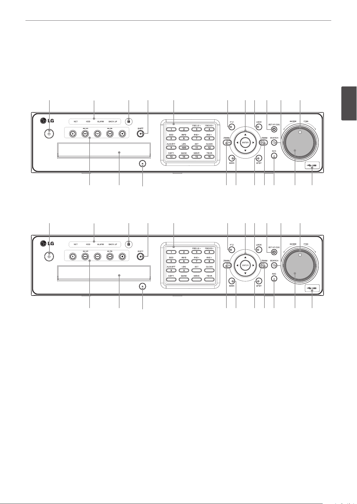
Front Panel
Front of the LE5016/LE4016 series
Preparation
9
a b
l m n op qor s t
Front of the LE5008/LE4008 series
a b
c d e f ghi j k
c d e f ghi j k
2
Preparation
l m n op qor s t
(Power): Turns DVR on or o. Press and hold for more than 2 seconds to turn on or o.
1
a
Indicator
b
• NET: Lights when the network is connected.
• HDD: Blinks when the HDD is accessed.
• ALARM: Lights when the alarm out is in progress.
• BACK UP: Lights when the data back up is in progress.
Remote Sensor: Point the remote control here.
c
SHIFT button: If you use the Sub-function of the channel button, the button is activated.
d
Channel Buttons: You can input a number with channel buttons. You can also use the channel buttons for sub-function with SHIFT
e
button (11 to 16 buttons of 8 channel DVR are used for sub-function without SHIFT button.).
• The LED in the button indicates the status as follows:
- O: The current status is for live mode.
- Red: Recording mode.
- Blinks when an event occurs.
Page 10

10
2
Preparation
Preparation
• Sub-functions
Button number Function Description
3/4
5 OSD Accesses or removes the System Control Bar (OSD).
6 INFO Displays or removes system information.
7/8 IRIS - / IRIS + Adjust iris position.
9 ALM.OFF
10/0 LOG Displays or removes the System Log List.
11 SET Registers the PTZ camera’s preset position.
12 CLEAR Deletes a memorized preset position.
13 COPY Copies the recording data to an external device.
14 MARK Sets the mark point for recording search.
15 MOVE Moves the camera to the preset position.
16 TOUR Tours all registered preset positions in the camera.
FOCUS -
/ FOCUS +
Adjusts focus position.
Cancels alarm activation and returns the system to the condition before the alarm was
activated.
PTZ: Switches this unit to PTZ mode to control the PTZ camera connected.
f
Arrow Buttons
g
•
b B v V
• ENTER: Conrms menu selections.
LOCK: Displays the lock menu to change the user type or disable the system operation.
h
SETUP/ESC: Displays the setup menu or cancels operation on the setup menus.
i
SEARCH: Displays the search menu.
j
Shuttle Ring: Fast forward or reverse picture search when the dial is rotated.
k
Playback Control Buttons
l
•X: Pauses playback.
•
m, ./c
•
bB
•
M, >/C
•x: Stops playback.
Disc Tray: Insert a disc here.
m
OPEN: Opens or closes the disc tray.
n
ZOOM + / -: Zooms in/out on playback window.
o
MAIN: Displays or removes the screen setup menu for MAIN monitor.
p
SPOT: Displays or removes the screen setup menu for SPOT monitor.
q
REC: Starts or stops instant recording.
r
JOG Dial: Allows a forward or reverse frame search. In pause mode, plays recorded images frame by frame through rotation. Increases
s
or decreases the options value.
USB Port: Connects an external USB device for backup or playback.
t
: Select or move between the menu options.
: Searches the recorded images in reverse or skips the recorded images.
: Playback or reverse playback of recorded images.
: Forward searches the recorded images or skips the recorded images.
Page 11
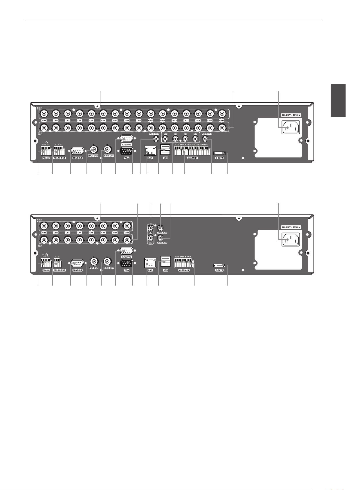
Rear Panel
Rear of the LE5016/LE4016 series
a b c
d e f g h i jklm no p q
Preparation
11
2
Preparation
Rear of the LE5008/LE4008 series
a
d e f g h i j lm o q
VIDEO INPUT: Connect the camera’s video output to these BNC connectors.
a
LOOP OUT: The signal from VIDEO INPUT connector is looped out to this connector.
b
Power Cord Inlet (AC IN): Connect the power plug.
c
RS-485 Terminals: Connect RS-485 compatible cameras.
d
RELAY-OUT Terminals: Output terminals for alarm (relay) signal.
e
CONSOLE: Used to connect to a host device equipped with RS-232C connector (such as a personal computer).
f
SPOT-OUT (BNC Type Connector): Connect to spot monitor or display device.
g
MAIN-OUT (BNC Type Connector): Connect to main monitor or display device.
h
ATM/POS: Used to connect to a ATM/POS device.
i
VGA: Connect a VGA monitor.
j
AUDIO OUT 1: Connect to an active speaker with a built-in amplier.
k
LAN Port: Connect the ethernet 10/100/1000 Mbps network cable for controlling this unit via a PC network.
l
USB Ports: Connect an optional extension USB device.
m
AUDIO INPUT: Connect the audio output of an external device.
n
ALARM-IN Terminals: Input terminals for alarm (relay) signal.
o
AUDIO OUT 2: Connect to an active speaker with a built-in amplier. Two-way audio output.
p
E-SATA: Connect the external SATA device.
q
b nkp c
Page 12
Preparation
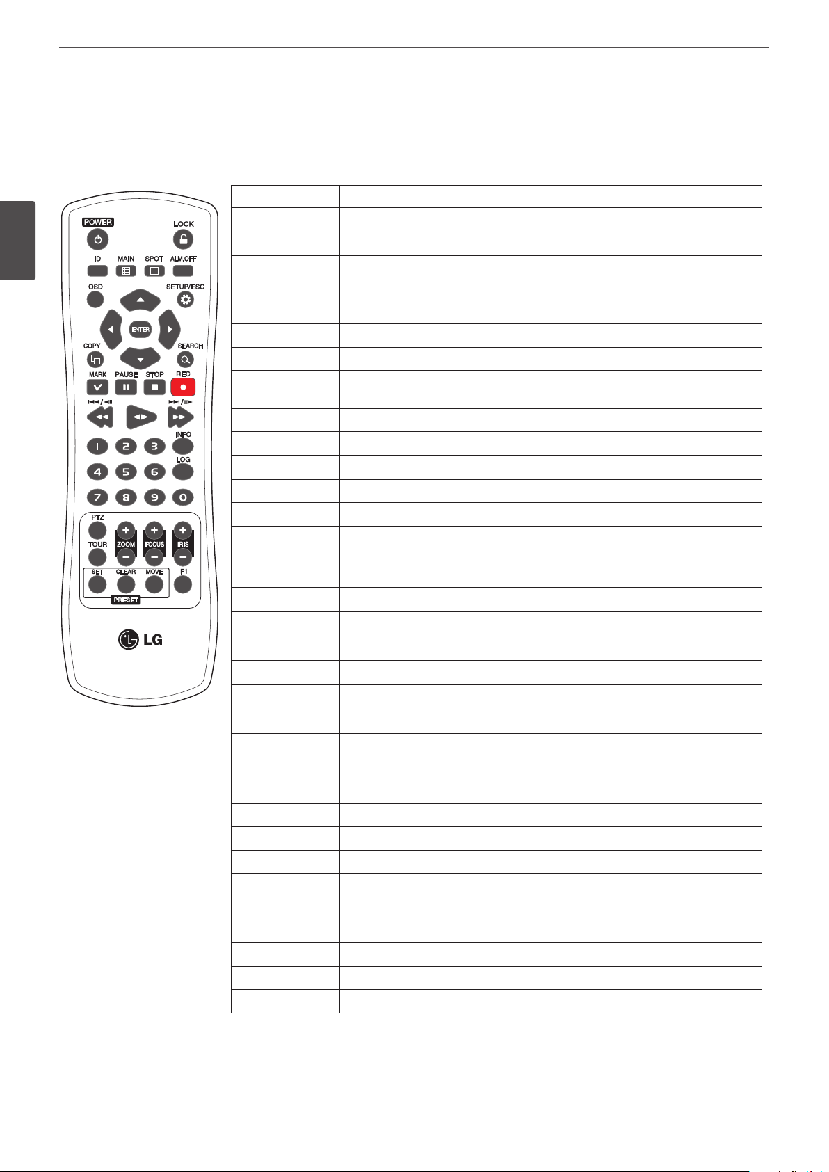
12
Remote Control
2
Preparation
Button Description
POWER (1)
LOCK
ID
MAIN
SPOT
ALM.OFF
OSD
SETUP/ESC
b B v V
ENTER
COPY
SEARCH
MARK
PAUSE (X)
STOP (x)
REC (z)
m, ./c
bB
M, >/C
Number Buttons
INFO
LOG
PTZ
TOUR
ZOOM + / -
FOCUS + / -
IRIS + / -
SET
CLEAR
MOVE
F1
Turns DVR on or o.
Displays the lock menu to change user type or disable system operation.
Set the appropriate DVR system ID to operate via the IR Remote Controller when
using the multiple DVR. Press the ID button then press the number button within
2 seconds to select the system ID of the DVR. If you set the system ID to “0”, you
can control multiple DVR at the same time.
Displays or removes the screen setup menu for MAIN monitor.
Displays or removes the screen setup menu for SPOT monitor.
Cancels alarm activation and returns the system to the condition before the alarm
was activated.
Accesses or removes the system control bar.
Displays the setup menu or cancels operation of the setup menu.
Selects or moves between the menu options.
Conrms menu selections.
Copies the recording data to an external device.
Displays the search menu.
Sets the mark point for recording search. You can set the mark point during the
single or multi channel playback of recorded data.
Pauses playback.
Stops playback.
Starts or stops recording.
Searches the recorded images in reverse or skips the recorded images.
Playback or reverse playback of recorded images.
Forward searches the recorded images or skips the recorded images.
To select the PTZ preset number, ID, or channel.
Displays or removes the system information window.
Displays or removes the System Log List window.
Switches this unit to PTZ mode to control the connected PTZ camera.
Tours all registered preset positions in the camera.
Zooms in/out on the playback window.
Adjusts the focus of a camera.
Adjusts the iris of a camera.
Registers the PTZ camera’s preset positions.
Deletes a memorized preset position.
Moves the camera to the preset position.
This button is not available.
Page 13
3
Installation
Connections
Installation
13
Precautions
• Depending on the camera and other equipment there are various ways to connect the unit. Please refer to the camera manual or manuals
for other devices as necessary for additional connection information.
• Be sure to switch o the camera before installation and connection.
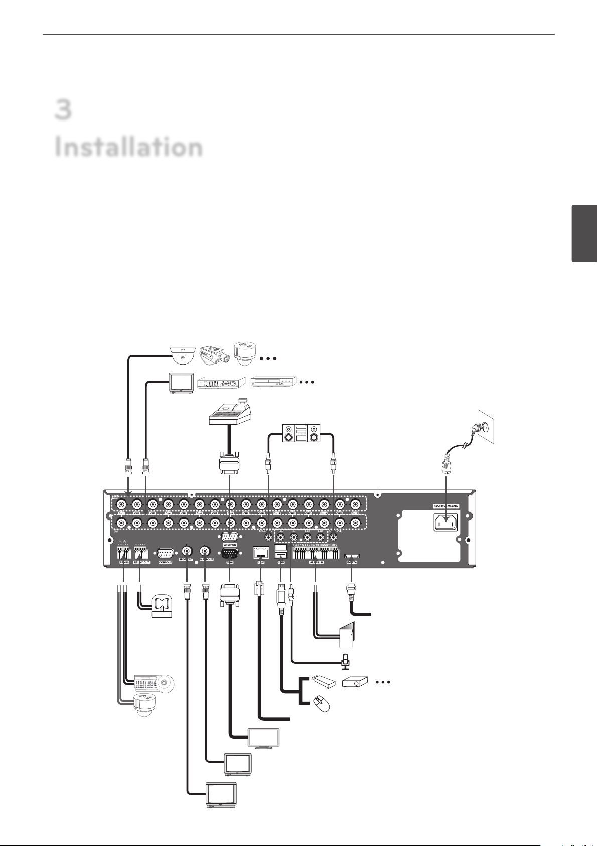
Basic Connection Overview
Connect the coaxial-type cameras
Connect the Monitor, DVR, VCR, or others.
Connect ATM/POS unit.
For audio amplier
Connect power
cord.
3
Installation
Connect the
alarm (relay)
Connect PTZ
cameras, DVRs
or keypads
(optional).
Connect the external SATA device for backup.
Connect alarm sensors.
Connect audio (line input)
Connect an external USB device for
backup or playback.
Connect a mouse device.
Connect network cable for client control or IP camera input.
Connect VGA monitor.
Connect BNC type monitor.
Connect BNC type spot monitor.
Page 14

14
Installation
Connecting Camera
Connect the video output of your camera to the unit, using a
standard 75 Ω video coaxial cable with BNC connector.
Camera connection
3
Installation
Connecting Display device
This unit can be outputted simultaneously from the VGA and MAIN
OUT jack. The video signal connection between the DVR and the
monitor.
CCTV(Composite Video Type) Monitor connection
Connect the unit to the CCTV monitor via 75 Ω video coaxial cables
with BNC connector.
VGA Monitor connection
Connect the VGA jacks on the rear of the unit to the corresponding
input jacks on the TV or monitor using the VGA cable.
VGA Monitor connection
SPOT Monitor connection
Connect the unit to the SPOT monitor via 75 Ω video coaxial cables
with BNC connector.
SPOT Monitor connection
CCTV Monitor connection
Connecting Audio device
Connect the AUDIO OUT jacks on the unit to the mono audio in
jacks on your audio device.
Microphone and Speaker connection
Page 15
Installation
15
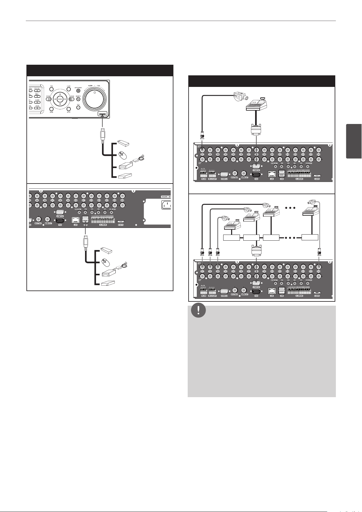
Connecting USB device
USB device connection
Connecting ATM/POS
Connect the ATM/POS unit to the ATM/POS port.
ATM/POS device connection
3
Installation
USB Memory device
Insert the memory device into the USB port. The system
automatically recognizes the device. Using a USB memory device
the system software can be easily upgraded.
USB External device
Connect the external device to the USB port.
(Example: External HDD or other external storage).
Mouse
Connect the mouse for function control of the unit.
NOTE
• The following device has been tested and compatibility is
ensured. When you use the multiple ATM/POS device use the
recommended device.
- AVE Products
› VSI-PRO: Video serial interface
› Regcom: RS-485 networker
› Hydra: RS-485 to RS-232 converter
• The installation and connection work should be done by
qualied service personnel or system installers and should
conform to all local codes.
Page 16

16
Installation
Connecting Network
You can control and monitor the system via network. With
the remote control (monitoring), you can change the system
conguration or monitors the image via network. After the
installation, check the network settings for the remote control and
monitoring work.
Network connection
3
Installation
Router
Connecting the PTZ device
Connecting the PTZ serial communication lines to the
RS-485 terminal.
PTZ device connection
Broadband
Service
5~7 mm
LAN connection
Connect the LAN port to an available 10/100/1000 base-T port with
a straight ethernet cable (not supplied). The NET indicator on the
front panel will be lit.
IP Camera connection
Connect the IP camera. After the installation, check the IP camera
settings on the setup menu.
Automatic network configuration
The DVR can automatically obtain and congure the network
interface via DHCP.
Manually configure network
The DVR may be manually congured by assigning an IP address,
subnet mask, gateway and DNS.
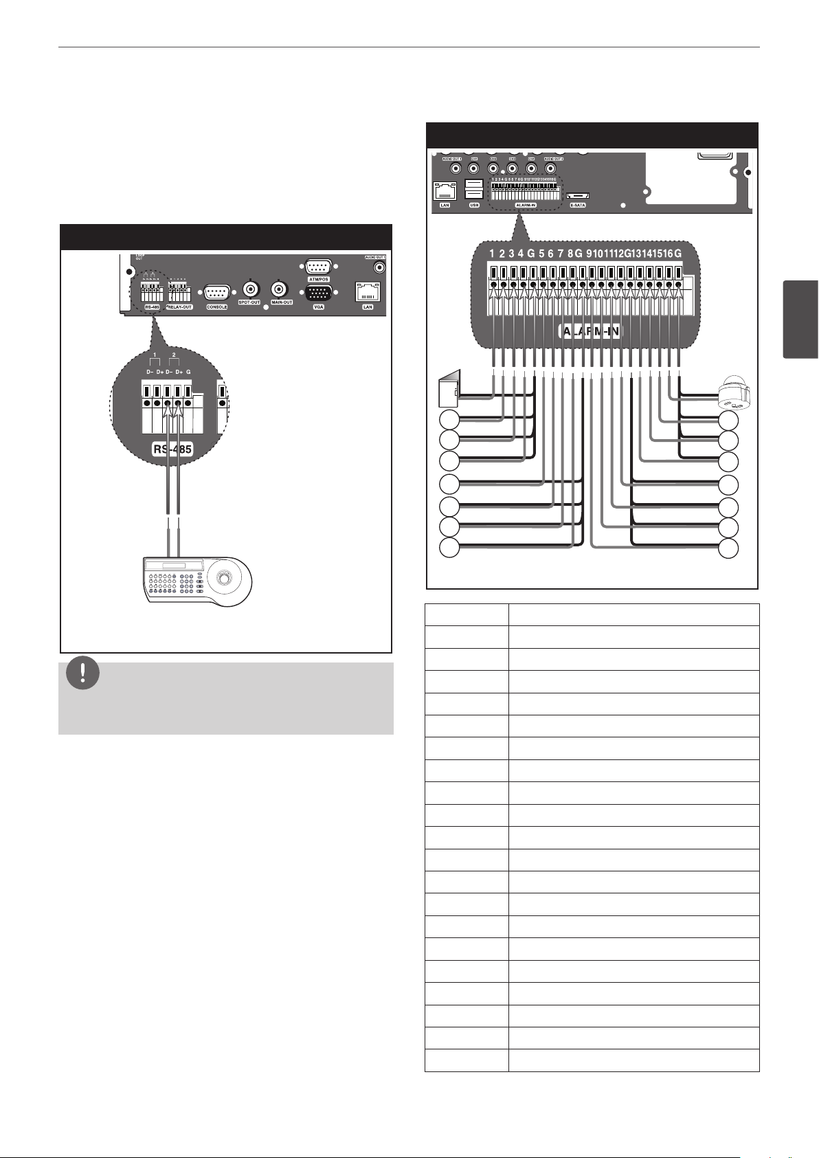
Connecting RS-485 device
This DVR has two data terminals. Use this port to connect PTZ
cameras, DVRs or keypads (optional).
RS-485 Terminal Description
D - (DATA -) Data Transmission/Reception
D + (DATA +) Data Transmission/Reception
GND Shield
PTZ units
(RS-485 type)
PTZ units
(RS-485 type)
NOTE
• When connecting lines, connect the “D -” of the DVR to “RX -”
of the PTZ unit and “D +” of the DVR to “RX +” of the PTZ unit
correctly.
• Recommended initial data are 9600 Baud Rate, 8 Data bits,
1 Stop bit and No parity.
• When connecting PTZ cameras to DVRs it is necessary to set
the setup menu for this unit according to the RS-485 settings
of the camera and DVRs.
Page 17
Installation
17
Connecting LKD1000 controller
Connecting the LKD1000 controller to control the DVR. (Refer to the
manuals of the LKD1000 controller for more details.). The LKD1000
controller have to be connected to the 2 (DATA 2) port as shown
illustration. If you connect the LKD1000 controller to the 1 (DATA 1)
port, the LKD1000 controller will not be activated.
LKD1000 controller connection
Sensor input connection
3
Installation
TX+TX-
LKD1000 Controller
NOTE
Do not connect a PTZ camera and LKD1000 controller at the same
time to the D1 or D2 port. It may cause a malfunction.
Connecting Alarm Input and Alarm Output
Alarm terminals are used to connect the alarm devices such as
sensors, door switches, etc.
Alarm Input
You can connect up to 16 alarm sensors (LE5008/LE4008: 8 alarm
sensors). Each alarm sensor should be connected with G (GND).
The signal state is adjustable to N/O (Normal Open) or N/C (Normal
Close) through the setup menu.
Alarm sensor Alarm sensor
Terminal No. Description
1 Sensor Input 1
2 Sensor Input 2
3 Sensor Input 3
4 Sensor Input 4
G Ground
5 Sensor Input 5
6 Sensor Input 6
7 Sensor Input 7
8 Sensor Input 8
G Ground
9 Sensor Input 9
10 Sensor Input 10
11 Sensor Input 11
12 Sensor Input 12
G Ground
13 Sensor Input 13
14 Sensor Input 14
15 Sensor Input 15
16 Sensor Input 16
G Ground
Page 18

18
Installation
Alarm Output
Connect the alarm device to the alarm output. Alarm signal output
at an event occurrence.
Alarm output connection
3
Installation
Alarm device
Terminal No. Description
G Ground
1 Alarm Output 1
2 Alarm Output 2
3 Alarm Output 3
4 Alarm Output 4
Alarm device
NOTE
The internal switching relays are rated for 0.3 A at 125 V AC or 1 A
at 30 V DC. If the electric current is higher than that the unit can
be damaged.
HDD INSTALLATION
Note for Hard Disk Drive
The internal hard disk drive (HDD) is a fragile piece of equipment.
Please follow the guidelines below when using the DVR to protect
against possible HDD failure. We recommend that you back up your
important recordings onto an external backup device in order to
prevent accidental loss.
Make sure that the power is turned OFF when attaching or
removing the HDD.
• Do not move the DVR while the power is on.
• Do not use the DVR in excessively hot or humid places, or in
places that may be subject to sudden changes in temperature.
Sudden changes in temperature can cause condensation to
form inside the DVR. This can be a cause of HDD failure.
• While the DVR is switched on, do not unplug from the wall
socket or switch the electricity o from the breaker switch.
• If there’s a power failure while the DVR is on, some data on the
HDD may be lost.
• Do not drop the HDD. Also do not put the metallic object such
as coins or screwdrivers into the HDD tray.
• When a power failure occurs during recording, avoid adding,
replacing or transporting the HDD as the recorded data may be
erased. In this case, turn the power back on to boot up the unit
normally with the HDD that was being used at the time of the
power failure attached. Then add, replace, or transport the HDD.
• The HDD is very delicate. Handle the HDD with care and follow
the precautions below because even a tiny shock may damage
the internal components of the HDD.
- Do not place the HDD on the desk or table directly. Put a
thick cushion under the HDD because even a small shock
may damage the internal components of the HDD.
- Do not use an electric screwdriver. Vibrations and shocks
caused by an electric screwdriver may damage the internal
components of the HDD.
- When replacing the HDD, do not knock the HDD with other
components such as another HDD and the HDD tray.
- Do not knock the HDD with tools such as a driver when
replacing the HDD.
• Protect the hard disk drives from static electricity.
Installing the Hard Disk Drive
You can install up to 4 HDDs.
Improper installation or setup may disturb HDD recognition or
normal product operation. So you should consult with an expert
from the store where the product was purchased.
1. Detach the top case by sliding it after removing the screws.
2. Remove the screws and detach the hard disk mounting brackets
from the unit.
3. Attach the HDD onto the hard disk mounting brackets with four
screws.
4. Attach the hard disk mounting brackets with the screws.
5. Connect the HDD power cable to the HDD.
6. Connect the SATA cable to the HDD.
Page 19
Installation
19
7. Connect the SATA cable to the SATA connector on the main
board.
8. Assemble the top case.
9. Fix the screws.
10. When you turn the power of the unit on, the new HDD is
detected and formatted automatically.
Replacing the Hard Disk Drive
Turn the power of the unit o and detach the power plug from the
outlet.
1. Follow steps 1 to 2 described in “Installing the Hard Disk Drive”.
2. Remove the connector from the HDD.
3. Remove the screws from the hard disk drive on the left/right
side of the hard disk mounting bracket.
4. Remove the HDD from the hard disk mounting bracket.
5. Install the new HDD.
6. After replacing the hard disk drive, insert the power plug into
the outlet and turn the power of the unit on. The new HDD is
detected and formatted automatically.
NOTE
• Make sure that each of the SATA cables is connected to the
connector housing through its holes.
• Do not use an electric screwdriver to x them.
System Operation
1. Turn on the unit. System booting will commence. The LG logo
image will be displayed on the main monitor during the system
booting.
2. When the booting is complet the live window will be displayed.
Click the LOCK icon on the system control bar or press the LOCK
button on the remote control to display the log-in window.
3. Select a user name by using the mouse or arrow and the ENTER
button on the remote control or front panel. For the rst time,
you can select the ADMINISTRATOR user name only. You can
register a new user with various access rights using the user
setup menu.
4. Enter the password by using the virtual keyboard. (Note that the
default administrator password is “000000”.)
5. Press the LOCK button or click the [OK] icon.
You can see the live screen and operate the system.
NOTE
• This DVR is based on a VGA monitor using OSD. We
recommend to using the VGA monitor with this unit. If you
use a composite monitor, the OSD quality may be low to read
it.
• If the DVR is turned o accidently and then turned on again,
the DVR may take a long time to be rebooted.
3
Installation
Recommended HDD
The following HDD has been tested and compatibility is ensured.
When you attach multiple HDDs use the recommended HDDs.
NOTE
If you do not use the recommended HDD, the system may not be
operated normally.
Maker RPM Capacity Interface Model No.
7,200 250 GB SATA ST3250311SV
Seagate
Hitachi 5,700 1 TB SATA HCS5C1010CLA382
7,200 500 GB SATA ST3500410SV
5,400 1 TB SATA ST31000424CS
System Shutdown
1. First, you must stop playback and exit the setup menu. In
playback, press STOP.
2. Press and hold
the logout window will be displayed.
3. Enter the password by using the virtual keyboard.
4. Press the LOCK button or click the [OK] icon. The system will
shutdown.
(POWER) button until the beep sounds and
1
Page 20
Installation
20
General Explanation of the Live
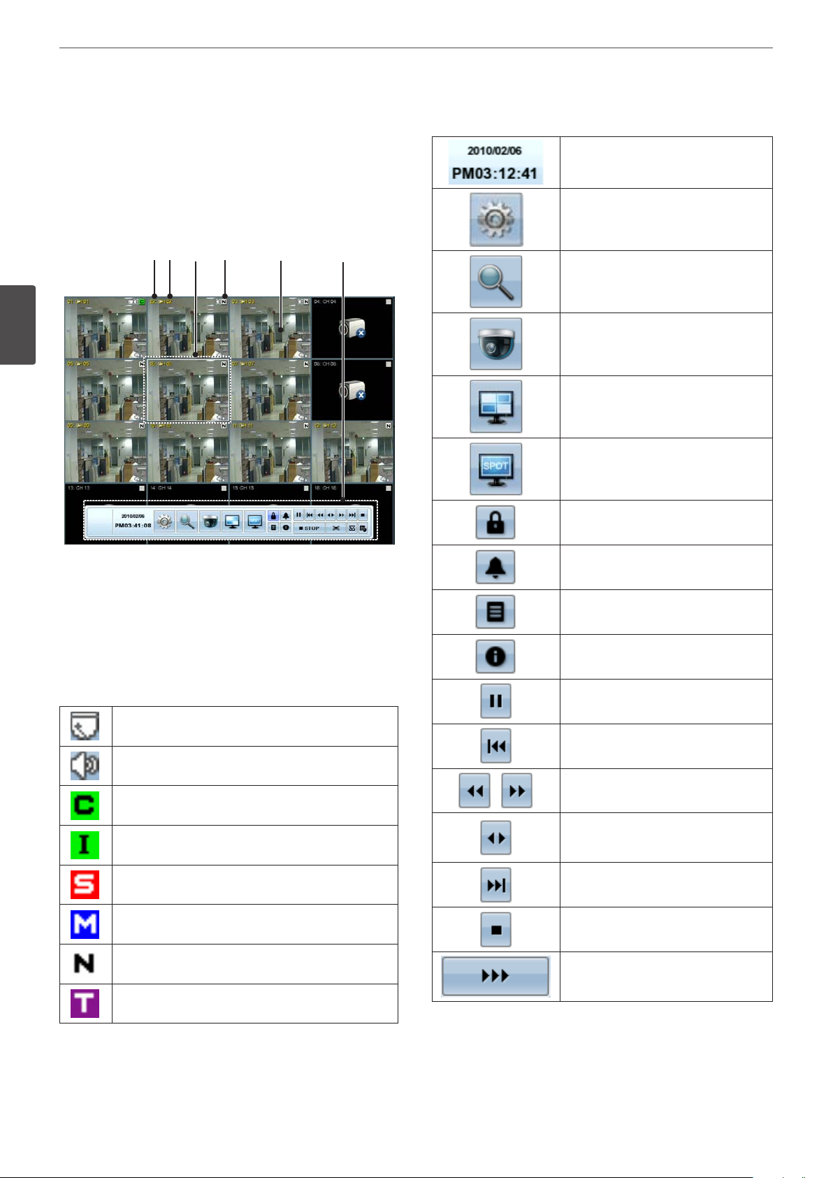
System Control Bar
f
Screen on the Main Monitor
Main Monitor Screen
abc d e f
3
Installation
Displays the current date and time.
Displays the setup menu.
Displays the search menu.
Displays the PTZ remote control window.
Displays the screen division selection
window for the main monitor.
Displays the screen division selection
window for the spot monitor.
Displays the lock menu to change the
user type or disable system operation.
Channel Number
a
Displays the channel number.
Channel Name
b
Displays the edited channel name.
Selected Channel
c
Displays the selected channel with white box.
Camera Status Icon
d
Displays the PTZ camera status.
Displays the input audio status.
Green “C” indicates continuous recording.
Green “I” indicates Instant recording.
Red “S” indicates sensor triggered recording.
Blue “M” indicates motion detection recording.
White “N” indicates the channel is not being recorded.
Turns the alarm o.
Displays the system log list window.
Displays the system information window.
Pause playback.
Jump to the beginning of the current
data recorded on the same date.
Select the required scanning speed.
Starts instant playback in selected
recording channel. If the recorded data is
empty, a warning message is displayed.
Jump to the last minute of the current
data recorded on the same date.
Stop playback.
Display playback status.
Violet “T” indicates text event recording.
Live Screen
e
Displays the current surveillance live screen.
Page 21
Installation
21
You can capture and save the current
image in JPEG le format. You should
connect the external device to save the
capture image.
1. Playback the recorded data.
2. Pause the playback at a desired point
during playback.
3. Click this button. The device
selection window is displayed.
4. Select a device and click [OK].
5. After saving the JPEG le, the
conrmation window is displayed.
Click [OK].
Click at a desired point to be marked
during playback. Up to 15 points can be
marked.
Display copy (export) menu.
NOTE
To display / remove the system control bar
Use OSD with the SHIFT button on the front panel or click the right
mouse button in live screen mode and then the system control
bar will be displayed or removed.
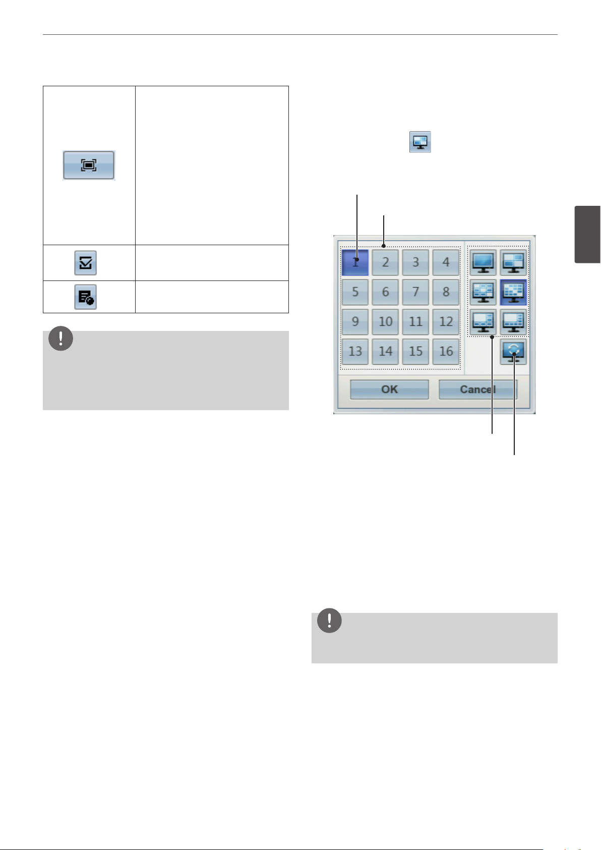
Selecting the Main Monitor screen mode
You can select the live screen mode to display a full, 4-split, 6-split,
8-split, 9-split or 16-split screens on the main monitor.
1. Press MAIN or click the icon in the system control bar.
Screen mode select menu of main monitor is displayed on the
main monitor.
2. Select screen mode.
Selected Main Channel
Channel Buttons
3
Installation
Screen split mode
Sequence mode
• Channel Number: Press the 1 to 16 channel button to see
the current surveillance images in selected live screens on
the main monitor.
• Full Screen Mode: When you see the selected channel on
the full screen.
• 4, 9, 16, 1+5 and 1+7 Split Mode: Displays selected split
screens on the main monitor.
• Sequence: View all channels in sequence. You cannot use
sequence mode with the 16 split (LE5008/LE4008 series: 8
split).
3. Select [OK] and press ENTER to conrm your selection.
NOTE
To display the screen you desire to watch in full screen mode,
double click the desired channel.
Page 22
22
Installation
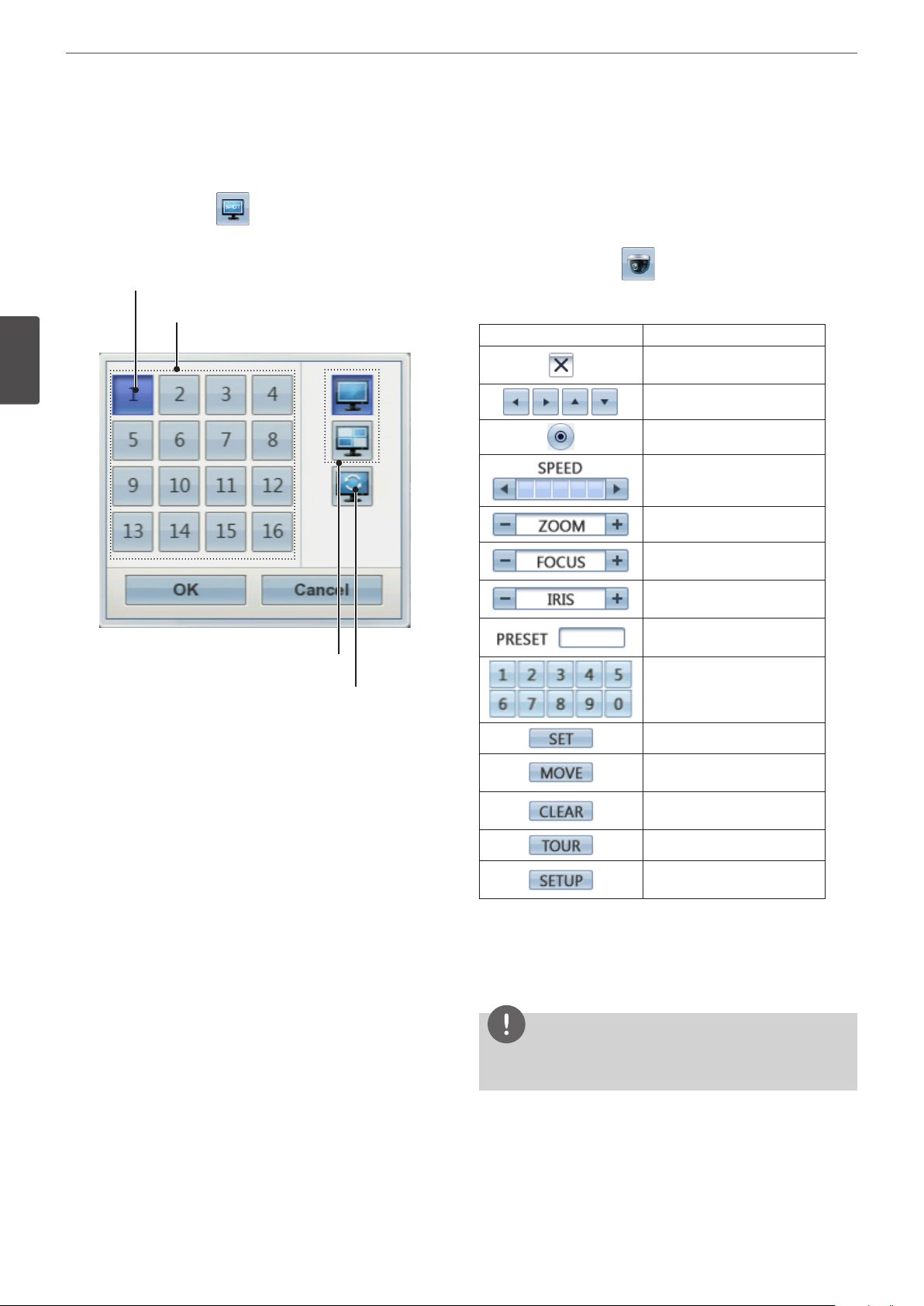
Selecting the Spot Monitor screen mode
You can select the live screen mode to full or 4-split screens on the
spot monitor.
1. Press SPOT or Click the icon in the system control bar.
Screen mode select menu of spot monitor is displayed on the
main monitor.
2. Select screen mode.
Selected Spot Channel
Channel Buttons
3
Installation
Screen split mode
PTZ Camera Control
You can control the cameras connected via the data port of RS-485
terminal. You must set the conguration between the PTZ camera
and the DVR.
1. Select the PTZ camera channel on the main monitor you want
to control.
2. Press PTZ or Click the icon in the system control bar.
Virtual PTZ remote control is displayed on the main monitor.
3. Use each item to control the PTZ camera.
Button Function
Remove the PTZ virtual remote
control.
Use to pan/tilt the camera.
Conrm the preset position.
Select the Pan/Tilt/Zoom
speed.
To adjust the camera zoom.
To manually adjust the focus of
a camera.
To manually adjust the iris of a
camera.
Displays the Selected Preset
number.
Sequence mode
• Channel Number: Press the 1 to 16 channel button to see
the current surveillance image on the spot monitor.
• Full Screen Mode: When you see the selected channel on
the full screen.
• 4 Split Mode: Displays 4 split screens on the spot monitor.
• Sequence: Views the all channels in sequence.
3. Select [OK] and press ENTER to conrm your selection.
To input the preset number.
To register preset positions.
To move the camera to the
preset position.
To delete a memorized preset
position.
To start a preset tour.
To displays the setup menu of
the PTZ camera.
Preset Settings
Preset position is the function to register camera monitoring
positions (preset positions) associated with position numbers.
By entering the position numbers, you can move cameras to the
preset positions.
NOTE
To activate this function, you need to register the preset positions
of the PTZ cameras.
Page 23
Installation
23
To Register Preset Positions
1. Move the camera to a point you wish by using the
, , , buttons.
2. Press SET or click the icon.
3. Select the preset number you wish to register.
4. Press ENTER or click the icon.
The position and its number are memorized.
5. Repeat steps 1 to 4 to add additional positions.
NOTE
Preset numbers from 0 to 255 are available on this unit but the
actual preset range diers depending on PTZ cameras.
Changing to a Picture in a Preset Position
The following function is available only with cameras provided with
the preset function. The preset function makes the combination
camera move to the programmed preset position. It is necessary to
program preset positions for the combination camera beforehand.
1. Press the MOVE button or click the icon.
2. Use number buttons to enter the memorized preset position’s
index number then press ENTER or click the icon. The
camera moves to the preset position and the picture of the
camera in that position appears on the monitor.
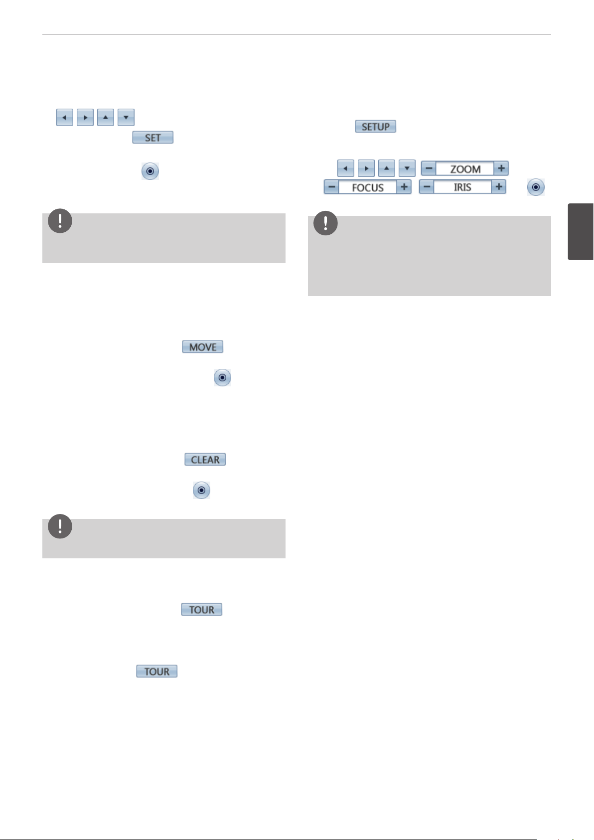
Setup for PTZ Cameras
You can adapt the camera to your requirements by setting up the
respective items in menus.
1. Click the icon.
The setup menu appears in the selected window of the main
monitor.
2. Use , , , , ,
, , and
buttons to set the options.
NOTE
• Refer to the manuals of the PTZ camera for more details.
• Some PTZ cameras may not operated correctly with this unit.
• You cannot control the other functions when the PTZ virtual
remote control is displayed.
3
Installation
To Clear the Preset Position
You can clear a memorized preset position.
1. Press the CLEAR button or Click the icon.
2. Use number buttons to enter the memorized preset index
number then press ENTER or Click the icon to clear the
preset positions.
NOTE
This function may not be available depending on PTZ cameras.
To Tour The Preset Positions
You can tour all preset positions.
1. Press the TOUR button or Click the icon.
All registered preset positions in the camera will be selected
and the camera position image will be switched on the active
monitor.
2. You can stop the tour by pressing the TOUR
button or clicking the
icon.
Page 24
24
Installation
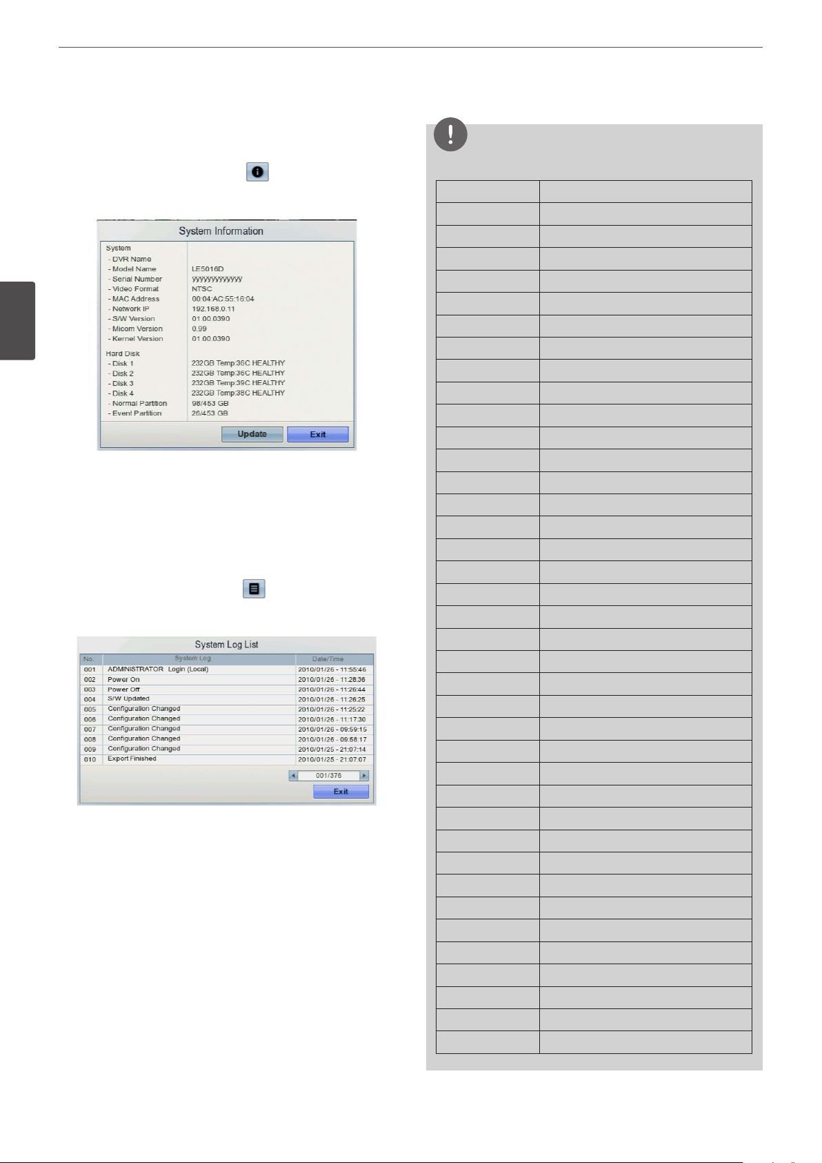
Viewing System Information
To view system information:
1. Press the INFO button or click the icon in the system
control bar. The system information window is displayed on the
main monitor.
3
Installation
• Update: Press this button to update the system information.
2. Press the INFO button or click the [Exit] button to exit the
window.
Viewing the System Log List
To view the system log list:
1. Press the LOG button or click the icon in the system
control bar. The system log list window is displayed on the main
monitor.
2. Use
3. Press the LOG button or click the [Exit] button to exit the
window.
to see the previous or next log list.
b / B
NOTE
Refer to the following system log list.
No. Log Message
1 Power On
2 Power O
3 Admin Login (Remote)
4 Admin Logout (Remote)
5 Admin Login (Local)
6 Admin Logout (Local)
7 Conguration Changed
8 Conguration Imported
9 Factory Default Set
10 Power Recovery
11 Backup Started
12 Backup Finished
13 Backup Failed
14 Export Started
15 Export Finished
16 Export Failed
17 S/W Updated
18 System Fan Failure
19 HDD Damaged (HDD1)
20 HDD Damaged (HDD2)
21 HDD Damaged (HDD3)
22 HDD Damaged (HDD4)
23 HDD Added (HDD1)
24 HDD Added (HDD2)
25 HDD Added (HDD3)
26 HDD Added (HDD4)
27 HDD Removed (HDD1)
28 HDD Removed (HDD2)
29 HDD Removed (HDD3)
30 HDD Removed (HDD4)
31 HDD Formatted (HDD1)
32 HDD Formatted (HDD2)
33 HDD Formatted (HDD3)
34 HDD Formatted (HDD4)
35 HDD Changed (HDD1)
36 HDD Changed (HDD2)
37 HDD Changed (HDD3)
38 HDD Changed (HDD4)
Page 25

Installation
25
Export the recorded data
This unit can manually copy recorded images and audio from builtin HDD to the external recording devices.
1. Press COPY or click the icon in the system control bar.
The export menu window appears.
2. Select [Target Device] then press ENTER.
3. Use
4. Press ENTER to conrm it.
5. Select the channel number and press ENTER. Repeat this step to
select multi channels.
6. Set the [Start Date/Time] and [End Date/Time] to copy.
•
•
• ENTER: Selects option or conrms the setting.
7. Press COPY or click the [Export] icon to start exporting. The
exported data will be authorized by the unit before saving and
it can only be played back with the exclusive player.
to select a target device to export.
b/B
b/B/v/V
b/B
: Moves to the options.
: Sets the selected option.
NOTE
• Check the export device before you proceed.
• You can also use the COPY button on the front panel for
export function.
• You can export the recorded data only in the live mode.
• If you use the external device, the external device has to be
formatted on this unit.
1. Connect the external device to the USB port on the front
or the rear of the DVR.
2. Select the [Format] icon then press ENTER.
Conrm window is displayed after format is completed.
3. Select [OK] and press ENTER to close the window.
• Check the size of the selected data and free space of the
external device. If the device does not have enough space,
create space on the device or erase the previously stored data.
• Export can not be executed while the backup is in progress.
• You can search the exported data with the supplied viewer
software.
• When you export the recorded data, the audio data will also
be exported.
• When you export the recorded data the export viewer
program will also be exported in the [ExportViewer] folder of
the device. The exported data le name is made automatically
as the [Channel name_export date_export time.exp] type.
• Do not remove the USB device while the export is in progress,
it may cause a malfunction.
• The warning message appears for the conditions listed below.
- When the start date/time and end date/time are the same
value.
- When the start date/time is later than the end date/time.
- The export media does not have enough space.
- When you set the time for data that does not exist.
• Anexternalmediahastobeformattedonthisunittoprevent
a malfunction.
• DVD+RWandDVD-RWdiscshavetobeinitializedbefore
using.
3
Installation
Page 26
26
Installation
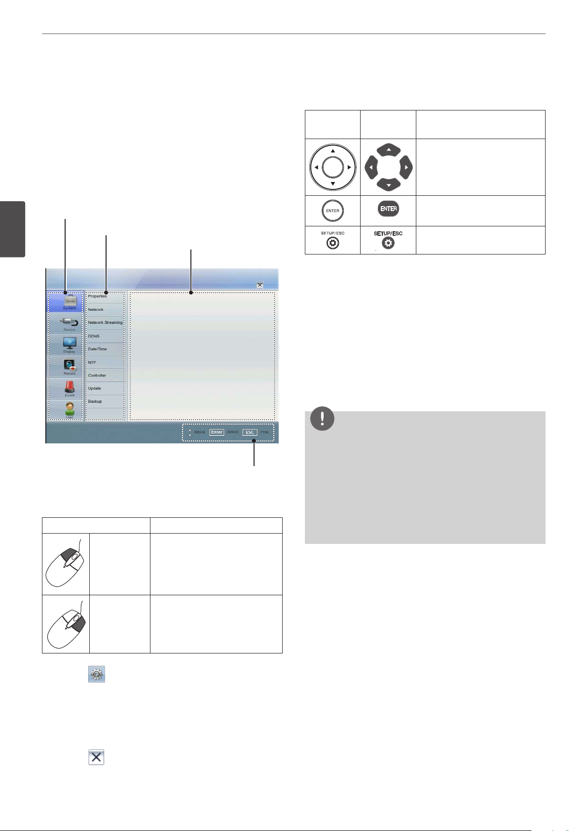
Configuration menu
The features and options of the DVR are congured through the
menu. The operations of this unit can be set via a menu displayed
on the main monitor. You can select and set the operational
conditions by using the buttons on the front panel and the remote
control or using a Mouse connected to the unit.
Only administrator-level users have permission to access the Setup
menu and congure the DVR.
First level
3
Installation
Second level
Third level
Setting the Menu Using the Front Panel Buttons or
Remote Control Buttons
Front Panel
1. Press SETUP/ESC to display the setup menu.
2. Use
v / V
to display the submenu.
3. Use
v / V
ENTER to display the setting options.
4. Use
v / V
the value.
5. Use
b / B
conrm your selection.
6. Press SETUP/ESC repeatedly to exit the Setup menu.
If the save message appears, select [OK] and press ENTER to
save the settings.
Remote
Control
Use these buttons to select the
menu options or adjust the
options value.
Select the option or conrm the
setting.
Return to the previous menu or
level.
to select the desired menu item, then press ENTER
to select the desired submenu item, then press
to select the desired option then press ENTER to set
to select the desired setting then press ENTER to
Description
Help menu
Using a mouse to set a menu
Use the left or right mouse buttons to set the menu.
Button Function
• Use to select a required item or
decrease the options value.
Left button
Right button Use to increase the options value.
1. Click the icon on the System control bar with the left
mouse button to display a setup menu.
2. Click the desired option with the left mouse button to display
the second or third level menu options.
3. Click the desired option with the left mouse button.
4. Set the selected options value.
• If you double click the button,
you can see the selected
channel on the full screen.
NOTE
• When you operate the function menu by using the remote
control and front panel buttons, both buttons are operated in
the same way to control the function menu.
• To use other functions of number buttons on the front panel
as shown below.
1. Press SHIFT. The button indicator turns red.
2. Select the function button you want.
• All the operation explanations are based on using the remote
control.
5. Click the icon to exit setup menu.
If the save message appears, click [OK] with the left mouse
button to save the settings.
Page 27

Installation
27
System settings
Properties
• DVR Name: Enter the DVR name using up to 20 characters.
• Language: Select a language for the setup menu and
information display.
• Button Beep: Marks up to activate the button beep. The button
beep is activated when using the buttons.
• Video format: Selects the video format to NTSC or PAL according
to your video system format. If you change the video format, the
HDD is formatted with selected video format. After the HDD has
been formatted, the conrmation message is displayed. Select
[OK] and press ENTER. The system will reboot.
NOTE
All cameras must be disconnected before you change the
video format to prevent malfunction.
• Conguration Import: Import the DVRs conguration data from
the USB memory stick.
• Conguration Export: Export the conguration data from this
DVR to the USB memory stick.
• Factory Default: You can reset the DVR to its original factory
settings. Some options cannot be reset (date, time, daylight
saving, time zone and user password settings).
Network
3
Installation
• DHCP: Select this option when a DHCP server is installed on the
network to allow IP address assignment. With this setting, the IP
address is assigned automatically.
• IP Address: Enter the IP address.
• Subnet Mask: Enter the subnet mask address.
• Gateway: Enter the gateway address.
• Primary DNS: Enter the Primary domain name server that
translates the hostnames into IP address.
• Secondary DNS : Enter the Secondary DNS server address that
backups the Primary DNS.
• TCP/IP Port: Enter the TCP/IP Port number. You can watch the
live surveillance image over the network with the PC Client
program. The factory default port for transmission of video and
audio data is 9001. However in some cases it is better to change
this port number for added exibility or security. You can edit
this port between 1 025 and 65 535.
• Web Server Port: Enter the Web Sever Port number. You can
watch the live surveillance image over the network with a web
browser. Typically the TCP port used by HTTP is 80. However in
some cases it is better to change this port number for added
exibility or security. You can edit this port to 80 or between
1 025 and 65 535.
• Audio Port: Enter the Audio Port number. You can edit this port
between 1 025 and 65 535.
• Bandwidth Throttle: Enter the Bandwidth to adjust the data
trac.
Page 28

28
Installation
Network Streaming
3
Installation
• Ch: Displays the channel number.
• Resolution: Selects the recording resolution. Each group such as
“Ch1 to Ch8” and “Ch9 to Ch16” are set the same resolution.
• Quality: Selects the recording picture quality.
• Frame Rate: Selects the frame rate. The frame rate is the number
of transportable frames per second. According to resolution, the
frame rate is set automatically. If you wish to set manually, refer
to the below.
Resolution Frame Rate
352*240 1, 3, 5, 7.5, 10, 15
NTSC
PAL
704*240 1, 3, 5, 7.5
704*480 1, 3
352*288 1, 3, 5, 6, 7.5, 12.5
704*288 1, 3, 5, 6
704*576 1, 3
• Host Name: Enter the host name you want to use.
You can not use the “www”, “mail”, “http”, “ftp”, “com”, “lg”, “lge”,
“lgddns”, “lgeddns”, “ddns” for host name.
• Registered Host: The registered host name appears.
• Update: Register the host name you typed in [Host Name] to LG
DDNS server.
How to register DDNS host name
With the DDNS function, you can easily use LG DVR.
When you use the DDNS function for the rst time after you
purchased LG DVR
1. Displays the DVR setup menu.
2. Select [System] > [DDNS] option.
3. Marks up for the [DDNS Service] option.
4. Enter the host name in the [Host Name] option.
5. Press the [Update] button. If host registration is properly
completed, the host name will be displayed in the [Registered
Host] option. If the host name is not registered after updating,
please check network connection.
When you want to change DDNS host name
If you want to change the registered host name to new one, follow
as shown below.
1. Enter a new host name in the [Host Name] option.
2. Press the [Update] button. The conrmation window will be
displayed to change your host name.
3. Click the [OK] button. When host name is properly changed, the
changed host name will be displayed in the [Registered Host]
option. If host name is not changed after updating, please check
network connection.
Date/Time
DDNS
This free service is very useful when combined with the LG DDNS
Server. It allows the user to connect the IP device using the URL,
rather than an IP Address. This also solves the problem of having a
dynamic IP address.
• DDNS Service: Marks up to activate the DDNS function.
• Date: Select the current year, month and day.
• Time: Select the current time.
• Date Format: Select the date display format.
• Time Format: Select the time display format.
• Time Zone: Select the time zone in the area where the DVR is
installed.
• Daylight Saving: Mark up when you use the daylight saving
function.
• Daylight Saving Start: Select the Daylight Saving start time.
• Daylight Saving End: Select the Daylight Saving end time.
Page 29

Installation
29
NTP
• NTP: Marks up, if you want to synchronize the DVR’s date and
time with those of the time server called NTP (Network Time
Protocol) Specify the NTP server’s name.
• Server: For most cases select public. The DVR will obtain the
average time among 5 public servers (time.nist.gov, time-a.nist.
gov, time-b.nist.gov, ntp.nasa.gov, clock.isc.org).
• Private Time Server: Enter the private time server’s IP address or
host name using the virtual keyboard.
• Sync. Interval: You can set synchronized intervals with the NTP
time server to 1 day, 1 week, 1 month and 1 hour.
• NTP Test: Select [NTP Test] to test the NTP server.
NOTE
If the NTP option is not set to this system, there can be a
gap between the system time and actual time. Using NTP is
recommended.
Update
3
Installation
The update feature allows you to upgrade DVR software and add/
upgrade PTZ protocols. In this case, the current DVR settings are not
deleted or replaced during the update process.
1. Connect the device including update le.
2. Select the update device from the drop-down list.
3. Select the [Search] button and press ENTER. The update le is
displayed in the list.
4. Choose the update le from the list.
5. Select the [Update] button and press ENTER. The conrmation
window is displayed.
6. Select [OK] to begin the update process or click [Cancel] to stop
and exit. After the update process is completed, the system
displays the Restart the system dialog box.
7. Click [OK] to restart the DVR.
Controller
• IR Remote ID: Select the IR Remote ID for this unit. If you use
multi systems set the IR Remote ID for each DVR unit.
• Remote Controller ID: Select the Remote Controller ID for this
unit. If you use multi systems, set the Remote Controller ID for
each DVR unit. You can control the DVR by using the LKD1000
controller. (For more details refer to the LKD1000 owner’s
manual).
NOTE
• Do not turn the power o during the update process to
prevent the malfunction.
• Do not remove the external device or CD/DVD disc for update
whilst the update is in progress. It may cause a malfunction.
Page 30

30
Installation
Backup
3
Installation
• Partition Selection: Select a backup partition.
• Schedule: You can set the backup schedule.
- OFF: All options are disabled.
- WEEKLY or DAILY: The backup data will be automatically
saved according to the setting.
- INSTANT: The backup data is saved manually.
• Device: Select a backup device.
• Schedule Start: Set the schedule start date (A day of the week
and time).
• Time Range Date: Enter the backup time range. Enter the date
you want to backup.
• Time Range Start: Enter the start day of the week or time.
• Time Range End: Enter the end day of the week or time.
• Estimate Size: Displays the size of backup data and the free
space of external devices.
• Start Backup: To start backup.
• Erase Media: To erase the media.
Instant Backup
1. Connect the backup USB device or insert a recordable disk to
the disc driver for backup.
2. Select the partition you want to backup.
3. Select INSTANT from the schedule options.
4. Select the backup device.
5. Select the Time Range Date, Time Range Start time, and Time
Range End time for backup.
6. Select the [Estimate Size] icon and press ENTER.
7. Check the size of the selected data and free space. If the device
does not have enough space, create space on the device or
erase the previously stored data.
8. Select the [Start Backup] icon and press ENTER to start backup.
9. Exit the setup menu. You can check the backup status on the
system control bar in backup progress.
3. Select the backup device.
4. Enter the date and/or time to start backup on the schedule start
option.
5. Enter the day of week and/or time on the Time Range Start
option.
6. Enter the day of week and/or time on the Time Range End
option.
7. Select the [Estimation Size] icon and press ENTER.
8. Check the size of selected data and free space of USB device. If
the USB device does not have enough space, change the USB
device to a USB which has enough space or erase data of the
connected USB device.
NOTE
• The backup function is not supported on the external USB CDROM driver.
• Available external device for backup.
Device Capacity
USB HDD Less than 1 TB.
E-SATA HDD Unlimited.
• Use the recommended external USB devices for preventing
malfunction (See page 69).
• The CD-R, DVD-R or DVD+R discs cannot be formatted.
• DVD+RW and DVD-RW discs have to be initialized before
using.
• An external media has to be formatted on this unit to prevent
malfunction.
• You cannot use the [Estimate size], [Start Backup] and [Erase
Media] options in backup progressing.
• Do not remove the external device while the backup is in
progress, it may cause a malfunction.
• If you format the external media by using a PC with FAT32, the
media may not be used on this unit.
• Check the size of the selected data and free space of the
external device. If the device does not have enough space,
create space on the device or erase the previously stored data.
1. Select the [Estimate Size] icon and press ENTER.
The size of the selected data and free space is displayed.
2. Select [OK] and press ENTER to close the window.
• You cannot stop the backup in backup progress.
• The warning message will appear for the conditions listed
below.
- When the start time and end time are the same value.
- When the start time is later than the end time.
- When you set the time for data that does not exist.
- When the start time and end time setting are wrong.
- A media does not have enough space.
- When the selected USB device is disconnected.
Daily/Weekly backup
1. Connect the USB device for backup. You cannot use the CD or
DVD writer for daily or weekly backup.
2. Select WEEKLY or DAILY on the schedule options.
Page 31

Installation
31
NOTE
• The disc burning is carried out by a single session closed
format.
• If you use the CD/DVD writer device for backup, it is making
ISO image and then writing the backup data to the CD/DVD.
• You can see the backup progress status on the system control
bar.
• The estimated size of backup data is only the approximate size.
So you must prepare sucient space on the media to prevent
lack of space.
• At the scheduled recording time, you can check the backup
status on the system control bar.
• While export is in progress or searching the backup data
from the external USB device, the scheduled backup will
not be started. After the export or backup search is nished,
scheduled backup will be restarted.
• When you set the schedule backup, the backup data size is
estimated from the recording settings of the Setup menu. If
the real recorded data size is over the estimated recording
data size, the schedule backup may not be activated.
Device settings
Camera
3
Installation
• Ch: Displays the channel number.
• Name: Enter the channel name using up to 20 characters.
• Audio: Select the input audio channel. You can hear from the
selected input audio channel. This function is not available for IP
channels.
PTZ
Settings for the PTZ cameras connected via the data port of the
RS-485 terminal.
• Channel: Selects the desired channel to set the connected PTZ
camera.
• Port: Selects the connected data port of the RS-485 terminal
on the rear panel. The DATA 2 port is used to control the PTZ
camera connected to DVR or to control by using the LKD1000
controller. If you want to use the PTZ camera via DATA 2 port,
you should set the [Remote Controller ID] to [NONE]. If you use
the LKD1000 controller to control the DVR via DATA 2 port, you
should set the [Remote Controller ID] number between 1 to 16.
• Control ID: Selects the PTZ camera ID. Make the same settings
as the PTZ camera.
• Protocol: Selects the protocol supported by PTZ camera.
• Baud Rate: Selects the communication speed.
Page 32

32
Installation
• PTZ Test: After the PTZ setting, you can test the pan/tilt function
for the selected PTZ camera. You can see the test screen from
the preview windows on the right side of the PTZ test option.
-
-
: Test the pan direction.
b / B
: Test the tilt direction.
v / V
NOTE
The supported PTZ camera list is on page 70 for reference.
IP Camera
3
Installation
• Channel: Selects the desired channel to set the connected IP
camera.
• Vendor: Selects the IP camera vendor from the drop-down list.
• Model Name: Enter the model name of the IP camera.
• Host Name: Enter the IP address of the IP camera.
• User Name: Enter the user ID.
• Password: Enter the user password.
• Port: Enter the port number.
• Test: Select [Test] to test the connection with the IP camera.
ATM/POS
• Interface Device: Select the interface device from the dropdown list.
- NONE: Selects when the ATM/POS device is connected with
the DVR directly.
- AVE Hydra: Selects when the ATM/POS device is connected
via the AVE Hydra device to the DVR. If you set to AVE Hydra,
the [Camera], [Baud Rate], [Data Bits], [Stop Bits] and [Parity]
options are dimmed and these options are not set.
• Camera: Select the camera number for mapping with ATM/POS
device.
• Baud Rate: Select the desired parameter to set the
communication speed between DVR and ATM/POS device.
• Data Bits: Select the number of the data bits for RS-485
communication.
• Stop Bits: Select the desired parameter. The stop bit, added to
the last of data, in asynchronous communication.
• Parity: Select the desired parameter. The parity bit, added to the
data, to perform parity check.
NOTE
The Supported IP camera specications.
Specication Description
Vendor LG, AXIS
Recording mode Continuous, Instant
Video Codec H.264 Baseline Prole
Audio recording and playback Not support
Resolution CIF, Half D1(2CIF), D1(4CIF)
Stream Master-0 only for LG camera
PTZ Not support
Sensor/Motion input Not support
Page 33

Installation
33
Storage
• Overwrite:
- ALL: Overwrite recording is possible when the normal
partition and event partition of HDD have fully recorded.
- NORMAL PARTITION: Overwrite recording is possible for
normal partition of HDD when the normal partition of HDD
has fully recorded.
- EVENT PARTITION: Overwrite recording is possible for event
partition of HDD when the event partition of HDD has fully
recorded.
- OFF: Do not use overwriting.
• Full Warning: When the HDD has overowed a warning message
is displayed.
• Auto Delete: Set the auto delete date. If you set the auto delete
date, the recorded data will be deleted except the data within
the selected date period of time. The Auto Delete function is
activated every 35 minutes.
• Event Partition: Set the space of event partition for event
recording. The motion and sensor recording data are saved in
the event partition area of the HDD. You should set the space of
event partition before event recording.
• Format: Initializes the HDD (Hard Disk Drive). All data on the
HDD will be erased.
Display settings
OSD
3
Installation
• Channel Name: Mark up to display or remove the channel name
in the channel window.
• Channel Status: Mark up to display or remove the channel status
in the channel window.
Sequence
NOTE
If you change the value of event partition, the current recorded
data of HDD is deleted and the partition is reset. The partitions will
be formatted automatically and the system will be restarted.
How to format the HDD
1. Select the [Event Partition] option and set the event partition
rate of the HDD. If you set the event partition to 60%, the
remaining space of 40% is set to normal partition automatically.
• Event Partition: To save space of the HDD for motion and
sensor recording data.
• Normal Partition: To save space of the HDD for instant or
normal recording data.
2. Select the [Format] icon and press ENTER.
3. Select [OK] and press ENTER to start format.
View all the channels in sequence in the selected screen division
mode. You cannot use sequence mode with the 16 split (LE5008/
LE4008 series: 8 split). While the sequence mode condition, if you
change the screen division mode, the sequence function will be
canceled.
• Main Dwell Time: Selects the channel sequence time for main
monitor.
• Spot Dwell Time: Selects the channel sequence time for spot
monitor.
Page 34

34
Installation
Channel Composition
3
Installation
• Ch: Displays the channel number.
• Name: Selects the desired channel. You can set the IP channel
only one time.
Video Adjustment
Adjust the brightness, contrast and color settings of each camera
channel. You can see the settings screen from the preview windows.
Record settings
Schedule
A schedule recording can be activated at preset times, in a repeating
pattern on selected weekdays. The DVR can record according to a
schedule set by the user. It can also record manually regardless of
date and time. The recording can be made either continuously or
triggered by events (alarm and motion detection).
The recording schedule screen displays one day of the week
showing the schedule of all channels over a 24-hour period. For
each 1-hour cell block the recording method can be specied. The
recording method for each block is shown in color for easy viewing.
Channel numbers
Time Line
• Channel: Selects the desired channel to adjust.
• Brightness: Adjust the brightness value from 0 to 100 for the
selected channel.
• Contrast: Adjust the contrast value from 0 to 100 for the selected
channel.
• Color: Adjust the color value from 0 to 100 for the selected
channel.
Recording mode
To Set the Recording Schedule for a Typical Day of the Week
1. Select a day of the week.
2. Select the desired channel to schedule recording.
Page 35

3. Select the time cell block for the start time.
4. Press ENTER or click the left mouse button to select a recording
mode. The color of the cell blocks will change automatically.
• Gray: No schedule recording.
• Green (Continuous recording): Recording starts
automatically from the preset time.
• Red (Sensor event recording): Recording starts automatically
when the sensor alarm occurs within a designated time.
• Blue (Motion event recording): Recording starts
automatically when motion is detected within a designated
time.
• Violet (Text event recording): Recording starts automatically
when text input is detected within a designated time.
• Yellow (Sensor+Motion recording): Recording starts
automatically when the sensor alarm signal has input or
motion has been detected.
• Green+Red (Continuous+Sensor event recording):
Recording starts automatically from the preset time. When
the sensor alarm occurs within a designated time, change
the continuous recording mode to sensor event recording
mode and recording starts automatically.
• Green+Blue (Continuous+Motion event recording):
Recording starts automatically from the preset time. When
the motion is detected within a designated time, change
the continuous recording mode to motion event recording
mode and recording starts automatically.
• Green+Violet (Continuous+Text event recording): Recording
starts automatically from the preset time. When the
text input occurs within a designated time, change the
continuous recording mode to text event recording mode
and recording starts automatically.
• Green+Yellow (Continuous+Sensor+Motion event
recording): Recording starts automatically from the preset
time. When the sensor alarm signal has input or motion has
been detected, change the continuous recording mode
to motion event recording mode and recording starts
automatically.
• Yellow+Violet (Sensor+Motion+Text event recording):
When the sensor alarm signal has input, motion has been
detected or the text input occurs and then recording starts
automatically.
Installation
• Sky blue (Continuous+Sensor+Motion+Text event
recording): Recording starts automatically from the preset
time. When the sensor alarm signal has input, motion has
been detected or the text input occurs within a designated
time, change the continuous recording mode to occurred
event recording mode and recording starts automatically.
5. Select the next time cell block of schedule time cell blocks to
conrm the schedule time.
6. Press ENTER or click the left mouse button repeatedly to select
gray to set the time for the end of the schedule. The settings cell
block is highlighted.
7. Press SETUP/ESC to move to the previous menu.
If the save message appears, select [OK] and press ENTER to
save the settings.
8. Press SETUP/ESC repeatedly to exit the Setup menu.
To Set a Recording Schedule for a Special Day
In addition to the weekly schedule, up to 10 specic date/time
periods can be dened. To congure the specic recording schedule
select Specic Dates.
1. Select the [SP] button on the schedule setting menu.
2. Select a cell block.
3. Press the [ZOOM +] button or click the [Add] icon on the special
day setting menu.
The specic date selection menu appears.
4. Enter the necessary information for year, month and date.
•
b / B / v / V
[Cancel] buttons.
•
5. Use
The virtual keyboard menu appears.
6. Enter the name of the special day. Use
character then press ENTER to conrm your selection.
7. Use
date of the special day and return to the special day menu
screen.
8. Select the schedule time and set the recording method for each
channel.
(or left/right mouse button): Changes the value at
b / B
the current position.
b / B / v / V
to select the [OK] icon then press ENTER to x the
v / V
: Press to move the columns, [OK] or
to select the [OK] button and press ENTER.
v/V/b/B
to select a
35
3
Installation
Page 36

36
Installation
Checking the Special Day Schedule List
1. Press [ZOOM -] when the [SP] button is selected.
The special day scheduled list appears.
2. Select a special day title on the list and press ENTER.
The title color turns orange.
3. Select the [Edit] icon then press ENTER to edit the special day or
press [ZOOM -] to delete the special day schedule.
4. Press ESC to exit the special day schedule list.
NOTE
If the special day recording schedule is duplicated with the other
recordings, only the special day recording is possible.
3
Installation
Copying the Recording Schedule
Copying from the Scheduled Data of the Channel
You can copy the schedule data of the channel to the other
channel(s) within the selected day of the week. You can not copy
the schedule data of the IP channel.
1. Select the day of the week and press ENTER.
2. Select channel that you want to copy.
3. Press COPY then the channel selection menu appears.
4. Use
ENTER to select the target channel(s).
You can cancel the selected channel by pressing ENTER.
5. Use
selection.
to move to the left or right column then press
b / B
to select [OK] then press ENTER to conrm your
v / V
Copying from the Scheduled Data of the Day
You can copy the scheduled day of the week to another day of the
week, weekday and weekend using the COPY button.
1. Select the day of week that you want to copy.
2. Press COPY then the select date(s) menu appears.
3. Use
4. Use
selection.
to select the target date(s).
b / B
to select [OK] then press ENTER to conrm your
v / V
Normal
Settings concerning normal recording.
• Ch: Displays the channel number.
• Resolution: Selects the recording resolution.
• Quality: Selects the recording picture quality.
• Frame Rate: Selects the frame rate. The frame rate is the number
of recorded frames per second. According to resolution, the
frame rate is set automatically.
NOTE
In case of the LE4000 series models, the resolution setting is
possible in the Normal setting menu only. Each group such as
“Ch1 to Ch4”, “Ch5 to Ch8”, “Ch9 to Ch12” and “Ch13 to Ch16” are
set the same resolution.
If you change the resolution of the Normal option, the resolution
of the Motion, Sensor, Text and Instant/Panic options will be
changed automatically with the same resolution.
Sensor
Settings concerning sensor recording.
• Ch: Displays the channel number.
• Resolution: Selects the recording resolution. The LE4000 series
models are displayed only.
Page 37

Installation
37
• Quality: Selects the recording picture quality
• Frame Rate: Selects the frame rate. The frame rate is the number
of recorded frames per second. According to resolution, the
frame rate is set automatically.
• Prealarm: Specify the pre-event recording time. When the Event
signal is detected, the DVR is recording the data before the
event during the setting time.
• Postalarm: Specify the post-event recording time. When the
Event signal is detected, the DVR is recording the data after the
event during the setting time.
Motion
Settings concerning motion recording.
• Ch: Displays the channel number.
• Resolution: Selects the recording resolution. The LE4000 series
models are display only.
• Quality: Selects the recording picture quality.
• Frame Rate: Selects the frame rate. The frame rate is the number
of recorded frames per second. According to resolution, the
frame rate is set automatically.
• Prealarm: Specify the pre-event recording time. When the Event
signal is detected, the DVR is recording the data before the
event during the setting time.
• Postalarm: Specify the post-event recording time. When the
Event signal is detected, the DVR is recording the data after the
event during the setting time.
Text
Settings concerning text recording.
3
Installation
• Ch: Displays the channel number.
• Resolution: Selects the recording resolution. The LE4000 series
models are display only.
• Quality: Selects the recording picture quality.
• Frame Rate: Selects the frame rate. The frame rate is the number
of recorded frames per second. According to resolution, the
frame rate is set automatically.
• Prealarm: Specify the pre-event recording time. When the Event
signal is detected, the DVR is recording the data before the
event during the setting time.
• Postalarm: Specify the post-event recording time. When the
Event signal is detected, the DVR is recording the data after the
event during the setting time.
Instant/Panic
Settings concerning instant/panic recording.
• Ch: Displays the channel number.
• Resolution: Selects the recording resolution. The LE4000 series
models are display only.
• Quality: Selects the recording picture quality
• Frame Rate: Selects the frame rate. The frame rate is the number
of recorded frames per second. According to resolution, the
frame rate is set automatically.
Page 38

38
Installation
IP camera
Settings concerning IP camera recording.
3
Installation
• Ch: Displays the IP camera channel number.
• Resolution: Selects the recording resolution.
• Quality: Selects the recording picture quality
• Frame Rate: Selects the frame rate. The frame rate is the number
of recorded frames per second. According to resolution, the
frame rate is set automatically.
NOTE
• If the video of some IP cameras is not displayed, you should
set the [Resolution] option to CIF (352x240 or 352x288).
• If you want to set the Frame Rate manually for each recoding
setting menu, refer to the below.
Event settings
Sensor
• In: Displays the number of the ALARM-IN terminal.
• Sensor Type: The sensor state can be set to either N.O. (Normally
Open) or N.C. (Normally Closed).
• Camera: Select the connected camera channel to the ALARM-IN
terminal.
• Relay Output: Select the alarm (relay) output number for the
RELAY-OUT terminal for the output alarm (relay) signal.
• Preset: Select the preset number. When the input is activated,
the camera moves to the selected preset position and the
picture of the camera in that position appears on the monitor.
NTSC
PAL
NTSC
PAL
LE5016/LE5008 Series
Resolution Frame Rate
352*240
1, 3, 5, 7.5, 10, 15, 30704*240
704*480
352*288
1, 3, 5, 6, 7.5, 12.5, 25704*288
704*576
LE4016/LE4008 Series
Resolution Frame Rate
352*240 1, 3, 5, 7.5, 10, 15, 30
704*240 1, 3, 5, 7.5, 10, 15
704*480 1, 3, 5, 7.5
352*288 1, 3, 5, 6, 7.5, 12.5, 25
704*288 1, 3, 5, 6, 7.5, 12.5
704*576 1, 3, 6
Motion
• Channel: Select the channel to set motion detection.
• Sensitivity: Set the level of sensitivity for the created motion
detection area. Sensitivity can be set from level 01 to 10 or OFF.
• Relay Output: Select the number of the RELAY-OUT terminal for
the output alarm (relay) signal when motion is detected.
• Area: Select the desired motion detection area on the preview
window screen.
-
b / B / v / V
zone.
: Moves the yellow cell box to another cell
Page 39

- ENTER: Selects or cancels the motion detection area at the
current cell position.
- Press ESC to exit the settings.
NOTE
• You can select the motion detection area by using the mouse.
- To select the area: Drag & drop a cell to the right to select
the motion detection area.
- To cancel area: Drag & drop a cell point of a selected cell
area to the left to cancel the motion detection area.
• In the condition that illumination is low and the outline of
object is not clear enough to see, regardless of sensitivity,
Motion Event could be possible not to happen. You must
check Motion Event before setting.
ATM/POS Data Format
The DVR can be set to react to text input from devices such as
ATMs (Automated Teller Machines) and POS (Point of Sale; i.e., cash
registers). This screen allows you to congure the DVR for your input
device.
NOTE
ATM/POS Recording Information.
Option setting ATM/POS Recording Action
Recording is started automatically
When the Transaction
Start and Transaction End
options are set.
When the Transaction
Start and Transaction End
option is not set.
when the Transaction start data is
detected. When the Transaction
end data is detected the recording
is stopped after post-alarm time.
Recording is started automatically
when the transaction data is
detected. When the transaction
data is not detected the recording
is stopped after post-alarm time
and the time you set of the Time
Out option.
Event Popup
Installation
39
3
Installation
• Input Channel: Select the mapping camera channel.
• Transaction Start: Enter a Transaction Start string. Refer to the
device manufacturer’s documentation for the text string that
the device rst sends when a transaction starts.
• Transaction End: Enter a Transaction End string. Refer to the
device manufacturer’s documentation for the text string that
the device sends when a transaction ends.
• Delimiter: Enter the character(s) that the device uses to
indicate the end of a line. Refer to the device manufacturer’s
documentation for Line Delimiter character(s).
• Ignore String: Enter the any strings of text that you want the DVR
to ignore. Refer to the device manufacturer’s documentation
for text strings that the device sends during transactions, so you
will know which ones you do not want recorded.
• Time Out: Select the Recording end time.
• Relay Output:
- 01 to 04: Outputs the alarm (relay) signal via the RELAY-OUT
terminal. When the DVR detects text input, it triggers output
signals on all the associated RELAY-OUT connectors.
- NONE: Not used.
• Spot Monitor: Select the event type for the spot monitor display
when the event is activated.
Notification
Marks up when you want to activate the selected option. If the
selected notication option is activated, the device will notify the
user about the information of selected option by E-mail.
Page 40

40
Installation
• Sensor On: Sends an e-mail when a sensor has occurred.
• Motion Detection: Sends an e-mail when a motion detection
has occurred.
• Text In: Sends an e-mail when a text input is detected.
• Admin Password Changed: Sends an e-mail when the
administrator password has changed.
• Video Loss: Sends an e-mail when a video signal from the
camera has stopped because of a cable disconnection or
malfunction of a camera.
• Power On/O: Sends an e-mail when power is on or o.
• Disk Full: Sends an e-mail when the HDD has fully recorded.
3
Installation
Emergency
• Notication: Marks up to notify the emergency agent about unit
operating information according to your notication settings.
• Host Name/Port: Enter the Host Name and port number of the
emergency agent program. The factory default port for this
function is 9002. However in some cases it is better to change
this port number for added exibility or security. You can edit
this port between 1 025 and 65 535.
You can set up to 9 Host Name and port numbers.
• Notication: Marks up to notify the unit operating information
according to notication settings by e-mail.
• SMTP Server: Enter the SMTP Server address.
If notication option is not mark up and the SMTP server option
is empty, the SMTP Port, User Name, Password and TLS options
cannot be set.
• SMTP Port: Enter the SMTP Port Number. Typically the port used
for SMTP is 25. However in some cases it is better to change this
port number for added exibility or security. You can edit this
port between 1 and 65 535.
• User Name: Enter the user name.
• Password: Enter the password.
• TLS: Marks up when using the TLS (Transport Layer Security)
function.
• Mail Address (1 to 3): Enter the mail address.
You can input up to 3 e-mail addresses.
• E-mail Test: Select [E-mail Test] to test send an e-mail.
NOTE
The SMTP server, SMTP port no., user name or password settings
are optional. The DVR can send e-mail directly without the use of
an SMTP server or MTA (message transfer agent). In certain cases
all e-mail should be forwarded to a specic SMTP server. Specify
the server host name or IP address in such a case. For more detail
on SMTP setup, ask your network administrator and/or mail service
provider.
Output
• Relay O
- ALARM ACKNOWLEDGE: Use the ALM.OFF button to stop
alarm.
- POST-ALARM TIME: The alarm is stopped after post-alarm
time.
• System Alarm Out: Outputs the alarm (relay) signal via the
selected alarm out terminal number below cases. If you do not
use this function, select [NONE] option.
- When the HDD has a bad sector.
- When a video signal from the camera has stopped because
of a cable disconnection or malfunction of a camera.
Page 41

Installation
41
Buzzer
Marks up when you want to activate the selected option.
• Sensor: Makes a sound when a sensor occurs.
• Motion : Makes a sound when a motion is detected.
• Text: Makes a sound when the DVR detects text input .
• System: Makes a sound when a cooling fan is not activated or
the HDD has bad sector.
User settings
Group Authority
You can register a new user group with various access rights.
3
Installation
• Group ID: Select the group ID to assign authority.
- GUEST: The GUEST group has the limited authority of the
system. Users in this group are available to see the live
image and to set the covert function of the Main or Spot
channel.
- ADMINISTRATOR: The ADMINISTRATOR group has the
unlimited authority of the system. Users in this group are
available to use all of the functions.
- [Group 01] to [Group 08]: Users in this group are available to
set the authority of the function manually.
NOTE
The GUEST and ADMINISTRATOR group are set initially for the
authority. You cannot change the initial settings and group name
(GUEST and ADMINISTRATOR).
• Group Name: If you select one of the group numbers from the
Group ID option, you can register the group name. Enter the
group name.
- Setup, Search/Play, Export, PTZ, Power O, Instant Record:
Set the authority for the selected group. Marks up the
option to activate it.
• Main Channel/Spot Channel: Selects the channel to allow the
operation for the group user. The LG logo is displayed on the
covert channel(s).
Page 42

Installation
42
User
You can set the user name for the selected User ID.
3
Installation
1. Select [User ID] from the drop-down list.
2. Enter the user name of the selected user ID.
3. Select the user group from the drop-down list.
4. Enter the Password.
5. Select the auto user logout time from the drop-down list.
6. Press the ESC button to display the conrmation window.
7. Select [OK] to save the setting or [Cancel] to cancel the setting.
NOTE
• If you set the user ID to [ADMINISTRATOR], you cannot change
the [User Name] and [Group] option but you can change the
password.
• The user name and password are case-sensitive.
Page 43

4
Operation
Operation
43
Instant Recording
Images from a camera will be recorded on the built-in hard disk.
Ensure all the cameras are connected and that time and date have
been set correctly.
Before you start recording, rst check the repeat recording settings
in the recording menu of the system setup, and then make the
recording settings.
1. Press the REC button and then press the channel button you
want to record. The recording type indicator turns green on the
selected channel screen of the main monitor.
2. Press the REC button and then press the channel button you
want to stop recording. If you stop instant recording, the
recording mode will be changed into the scheduled recording
mode (Continuous/ Alarm/ Motion records). If the schedule is
not set, the button indicator turns o and the recording type
indicator turns white on the selected channel screen of the
main monitor.
Panic Recording
You can record the all channels at the same time.
This function is activated for a live channel only.
1. Press and hold the REC button until the Recording Type
indicator turns green on the all live channel screens.
The DVR will start recording.
2. Press and hold the REC button until the Recording Type
indicator turns white on the all live channel screens. The DVR
will stop recording.
NOTE
• External recording devices can be used as copy areas for
images recorded on the hard disk. It is impossible to record
images on the external recording devices directly.
• You can record instantly with the left mouse button.
1. Move the cursor to the desired channel screen on the
main monitor.
2. Click the recording type indicator with the left mouse
button and recording starts. Click it once again and the
instant record stops and the recording type indicator
will be changed into the scheduled recording mode
(Continuous / Alarm / Motion record). If the schedule is
not set, the recording type indicator turns white.
• You can instant record that the channels scheduled such as
alarm, motion or continuous.
• Once you stop instant recording, the recording type indicator
will be changed to the scheduled recording mode.
• You can not record the Instant and Continuous recording in
following conditions.
- A HDD is not attached.
- A HDD is not formatted.
- The channel has no video input for display.
- Overwrite sets to “OFF” or “EVENT PARTITION”, and normal
partition is full.
- On the HDD setting, the event partition is set to 100 %.
• You can not record the Alarm and Motion recording in
following conditions.
- A HDD is not attached.
- A HDD is not formatted.
- The channel has no video input for display.
- Overwrite sets to “OFF” or “NORMAL PARTITION”, and event
partition is full.
- On the HDD setting, the event partition is set to 0 %.
- The schedule (Alarm/Motion) record is not set.
• HDD partition according to a recording type.
- Normal Partition: It is the space in the HDD that stores the
continuous and instant recorded data. Once the normal
partition is set to 0% (the event partition is 100%), you can
not record the continuous or instant recordings.
- Event Partition: It is the space in the HDD that stores the
alarm and motion recorded data. Once the event partition
is set to 0%, you can not record the alarm and motion
recording.
• Priority of record.
Instant record > Alarm record > Motion record > Continuous
record.
4
Operation
Page 44

44
Operation
Instant Playback
It is possible to play a recorded image without stopping recording.
1. Select a channel you want to playback.
2. Press
1 or 2 minutes of recording. The playback image will be
displayed on the full screen window.
3. Press
(Play) button to play a recorded image of the previous
bB
(STOP) button to stop the playback.
x
Search and Playback
The various search functions of this unit can be used to go to the
beginning of the desired picture.
When the SEARCH button is pressed the search menu is displayed.
4
Operation
Date and Time Search
Use to search recorded pictures by specifying date, hour and
minute.
8. Press SETUP/ESC to exit the[Date/Time] menu.
Using the calendar icon to select the date
1. Select calendar icon then press ENTER.
2. Select year or month column then press ENTER.
3. Use
4. Press ENTER to conrm it.
5. Use
6. Select [OK] button and press ENTER to conrm the settings.
button to input the year or month.
b/B
v/V/b/B
to select date then press ENTER.
NOTE
• While the backup is in progress, you can not search the data
on the backup device.
• Do not remove the external USB device whilst the backup
search is in progress from the USB device. It may cause a
malfunction.
• Recorded data shown on the time graph will be displayed in
dierent colors depending on the recording type.
- Green: Continuous recording.
- Red: Sensor recording.
- Blue: Motion-detection recording.
- Gray: No recording.
- Violet: ATM/POS recording.
• Use the ZOOM + button to view the detailed time by 6 hour
intervals.
1. Use
ENTER.
2. Select the desired source device.
• INTERNAL HDD: Plays back or searches recorded contents of
• Source Device: Plays back or searches backup contents of
3. Set the year, month, date and time.
•
•
• ENTER: Selects the column or conrms the setting.
4. Select the [Search] icon then press ENTER.
The search result is displayed.
5. Use
this step to select the other channels.
6. Press
playback.
The picture(s) is (are) displayed on the main monitor.
7. Press STOP (
button to select the [Date/Time] icon then press
v/V
the internal HDD device.
the source device.
: Moves to the previous or next column.
b/B
: Changes the value at the current position.
v/V
button to select the channel and press ENTER. Repeat
v/V
(Play) button or click the [Play] button to start
bB
) to stop playback and return to the search menu.
x
Event Search
Search a recorded picture by date and type of event.
1. Use
2. Select the desired source device.
3. Set the year, month, date and time.
•
•
• ENTER: Selects the column or conrms the setting.
4. Use
button to conrm the selection. If you want to select the all
channels, marks up the [All Channels] option.
5. Select the [Event Type] then press ENTER.
6. Use
button to select the [Event] icon then press ENTER.
v/V
: Moves to the previous or next column.
b/B
: Changes the value at the current position.
v/V
v/V/b/B
v/V
button to select the channel and press ENTER
to select the event type then press ENTER.
Page 45

Operation
45
7. Select the [Search] icon then press ENTER.
The event list menu appears.
8. Select the recording data on the event list then press
button, click [Play] or double click the selected data to start
playback.
The picture is displayed on the main monitor.
9. Press STOP (
menu.
10. Press SETUP/ESC repeatedly to exit the event search menu.
) to stop playback and return to the event list
x
bB
Bookmark Search
Search the desired picture with a bookmark registered by the
bookmark function.
1. Use
ENTER.
2. Select the recording data on the list then press
[Play] or double click the selected data to start playback.
The picture is displayed in the main monitor.
3. Press STOP (
menu.
4. Press SETUP/ESC to exit the bookmark search menu.
• Backup data can not be played back by a bookmark search.
• You can register a bookmark only in the single channel
playback.
• If you delete the bookmark on the list, select the recording
data and select [Delete] button and press ENTER.
button to select the [Bookmark] icon then press
v/V
) to stop playback and return to the bookmark list
x
NOTE
(Play), click
bB
(Play)
ATM/POS Search
Search the recorded text information by ATM/POS device.
This function is available with backup data of the internal or external
HDD only.
1. Use
2. Select the desired source device.
3. Set the year, month, date and time.
•
•
• ENTER: Selects the column or conrms the setting.
4. Use
button to conrm the selection. If you want to select the all
channels, marks up the [All Channels] option.
5. Set the detail search options.
• Number: Displays the preset number.
• Option Item: Enter the text to search what you want.
• AND /OR : Select the Boolean operator when you use the
• Value: Enter the number to search what you want.
• >, <, <=, =, >= (compare symbols): Select the compare
button to select the [ATM/POS] icon then press ENTER.
v/V
: Moves to the previous or next column.
b/B
: Changes the value at the current position.
v/V
v/V/b/B
Text search and Number search function simultaneously.
symbol for number search.
> To nd the lower value than the input value.
< To nd the higher value than the input value.
<= To nd the higher or even value than the input
= To nd the even value than the input value.
>= To nd the lower or even value than the input
button to select the channel and press ENTER
value.
value.
4
Operation
6. Select the [Search] icon then press ENTER.
7. Select the text data on the list then press
[Play] or double click the selected text data to start playback.
The picture is displayed on the main monitor.
8. Press STOP (
search list menu.
) to stop playback and return to the ATM/POS
x
(Play) button, click
bB
Page 46

Operation
46
Export Search
Search an exported data from the external device or internal
DVD-ROM device.
If you want to use this function, you have to connect the external
device or insert the CD/DVD disc with exported data otherwise the
warning message will be displayed.
Check the export device before you proceed.
4
Operation
1. Use
2. Select the desired source device.
3. Select the [Search] icon then press ENTER.
The exported le list menu appears.
4. Select the exported le on the exported le list then press
(Play) button or click [Play] to start playback.
The picture is displayed on the main monitor.
5. Press STOP (
list menu.
button to select the [Export] icon then press ENTER.
v/V
) to stop playback and return to the exported le
x
bB
Page 47

Functions Available During Playback
Button
System Control
Bar
Remote Control Front panel
Stop playback.
Pause playback.
Jump to the beginning of the current data that was recorded on the same
date. (press the button for more than 2 seconds.)
Jump to the last 1 minute of the current data that was recorded on the
same date. (press the button for more than 2 seconds.)
Function
Operation
47
4
Operation
NOTE
Press repeatedly to select the required scan speed. (
MBM
Press repeatedly to play frame-by-frame in pause mode.
Press to play reverse or normal playback.
Press MARK at a desired point to be marked during playback. Up to 15
+
points can be marked.
or m,
bm, mm, bmm
M, MB, MM
)
,
• You can play the backup or export data in normal speed only.
• If you use the reverse frame skip function, a frame may be skipped.
• Multi channel play works only in the date/time search function.
• If you double-click the channel during the multiple channel playback, the selected channel will be played on the full screen. And if you
double-click the channel during playing full screen mode, it will return to the previous playback condition.
Page 48

LG Network Client Program
48
5
LG Network Client Program
Introduction
The LG Network Client program is an IP-Surveillance software that
works with the LG DVR to provide video monitoring, recording
setting and event management functions. The software has multiple
search functions for recorded events. Remote viewing and playback
are also possible with the use of the LG Network Client.
This manual contains instructions on how to use and manage
the LG Network Client in your networking environment. Some
knowledge of networking environments would be benecial to the
reader.
Should you require any technical assistance, please contact
authorized service center.
5
LG Network Client Program
Recommended PC Requirements
The LG Network Client program must be installed below operating
systems for best performance and stability.
Items Requirements
Operating System Windows XP Professional Service Pack 2 or
above
CPU Intel Pentium IV or above
Web Browser Microsoft Internet Explorer 6.0 or above
Memory 512 MB or above RAM
Graphics Card 128 MB or above Video RAM (Use latest
graphics card driver.)
Resolution 1024 x768 (with 32bit color) or above
Network 100 Megabit Network (Gigabit Network
recommended for larger systems)
Getting Started
Install the LG Network Client on your PC
You can install the LG Network Client software following steps.
1. Insert the Client Program CD which will be started automatically.
If the disc does not run automatically on your PC, open the
Client Program CD and install the program manually.
2. Run the install le and install the programs to your computer
following the on-screen instructions. The [LG Emergency Agent]
and [LG Export viewer] programs will be installed with the LG
Network Client program installation.
3. After nishing installation, you will nd the programs in the Start
menu or on the desktop.
Starting the LG Network Client
1. Run the LG Network Client program. To launch LG Network
Client, select LG Network Client from your Start > Programs >
LG Electronics > LG Network Client > LG Network Client or
click the LG Network Client icon on your desktop.
The client password input window is displayed.
2. Enter the password. (Note that the default client password are
“000000”.)
3. Click the [OK] button and then the LG Network Client window is
displayed.
NOTE
If you mark up the [Auto Connection] option, the LG Network
Client program is connected automatically at the next time.
Before install the program
• The description pictures may dier from your OS (Operating
System) or Web Browser type.
• The pictures used in this manual are based on Windows XP
Professional.
• Do not use other applications with this program. This can cause
memory shortage and program malfunction.
• Check that the LG DVR is(are) connected to the network and
that power is supplied.
Page 49

LG Network Client Program
49
LG Network Client Overview
Selected Menu Tab
Menu Bar
Information Display Window
Tool Bar
Playback control Window
Menu Bar
Menu Sub-Menu Description
File Client Password You can change the password of the
Network Client program.
1. Select this option. The Client
Password Setup window is
displayed.
2. Enter the password.
3. Click [OK] to conrm your
settings.
Save to JPEG You can capture and save the current
image in JPEG le format.
1. Play the recorded data.
2. Pause the playback at a desired
point during playback.
3. Select this option. The JPEG
Export window is displayed.
4. Set the options.
5. Click the [Save] button.
Backup Search Search and playback a backup data.
1. Select the Search Mode icon.
2. Select this option. The Backup
Search window is displayed.
3. Click the [Add] button.
4. Enter the Name.
5. Find and open the backup le.
6. Click the [OK] button.
7. Use the time line and playback
control buttons to play the
backup data.
Live window
File End Backup
Search
Software Update Use to upgrade DVR software or add/
Exit Exit the program.
View OSD • Channel Number: Displays or
Sequence (Dwell
Time)
Sequence Mode • Channel Sequence: Each channel
Use to stop and exit the backup
search function.
upgrade PTZ protocols.
1. Log-in the Network Client
program as the permitted
user who has the Group Setup
authority.
2. Click this option. The Update
setting window is displayed.
3. Select the update device from
the list.
• Select All: If you click this
button, the all devices in the
list are selected .
• Clear All: If you click this
button, the all selected
devices in the list are
deselected .
4. Find and open the update le.
5. Click the [Update] button to
begin the update process.
The DVR will be restarted after
updating.
6. Click the [Exit] button.
removes the channel number in
the channel window.
• Site Name: Displays or removes
the site name in the channel
window.
• Camera Name: Displays or
removes the camera name in the
channel window.
• Playback Time: Displays or
removes the date/time of
playback data in the channel
window.
• PTZ: Displays PTZ camera icon in
the channel window.
• Audio: Displays audio icon in the
channel window.
• Select All: Displays all OSD
options in the channel window.
Select the sequence to 5 seconds, 10
seconds, 15 seconds or 20 seconds.
of the selected site in the
sequence mode will be displayed
in sequence.
• Site Sequence: Each channel of
the logged site in the sequence
mode will be displayed in
sequence
5
LG Network Client Program
Page 50

LG Network Client Program
50
5
LG Network Client Program
View Language Select the language for LG Network
Client program.
Resolution Select the resolution of the LG
Network Client program.
Tools Connection
Information
E-Map Displays the E-Map pop-up windows.
Help Client
Information
Displays the Connection List
windows. Add, Edit or Delete the site
name or group name in LG Network
Client.
This function gives a visual overview
of the cameras in your surveillance
environment using the imported
maps.
Displays Network Client Version
Information.
Tool Bar
Icon Description
Displays the live view workspace.
• Camera View: You can see the
surveillance camera’s images in
the window(s) and the camera
information.
• Pan/Tilt/Zoom: You can control the
Live
PTZ camera.
• Log View: You can see the system
log list.
• Favorites: You can save the current
conguration of the camera view.
And, it is possible to return to a
previous conguration of the camera
view.
When the icon is clicked, the screen
will be changed to split mode and if
the icon is clicked again, the screen will
be changed by sequence (except 36
split mode). Choose the screen division
mode.
Division
View all the channels in sequence. You
cannot use sequence mode with the 36
Sequence
split.
Information Display Window
Displays current date and time, user information and the remaining
HDD status of the selected site name.
Playback control Window
You can playback the recorded data of the selected channel.
Search
Setup
Export
Print
Full Screen
Displays the search workspace. You can
search and play the recorded data using
the search functions.
You can set the conguration of the
selected site via the network.
Displays the Export pop-up windows.
When you click the PAUSE button to
pause the playing the recorded data
of the selected channel, the Print Icon
is activated. You can print the paused
picture of the recorded data of the
selected channel.
You can view the live window in full
screen mode. To return to the normal
screen, click the right mouse button.
Page 51

LG Network Client Program
51
Operation and settings
Register the Site Name or Group Name
The rst time LG Network Client is started, you should register a site
name to control it by the LG Network Client program. The computer
running LG Network Client program must be on the same network
with DVR.
1. Select [Tools] > [Connection Information] option on the menu
bar. The Connection List window is displayed.
2. After completing the settings, click the [OK] button to conrm
the settings and exit the window. The registered site or group
name is(are) displayed on the [Camera View] tab window.
Create a new group name
1. Click the [Add Group] button. The Add Group window is
displayed.
2. Enter the group name.
3. Click the [OK] button to conrm it.
The registered group name is displayed on the Connection List.
Edit a group name
1. Select the required group name on the Connection List.
2. Click the [Edit] button. The Edit Group window is displayed.
3. Overwrite the existing group name with a new name that you
want.
4. Click the [OK] button to conrm it.
Delete a group folder
1. Select the required group name on the Connection List.
2. Click the [Delete] button. The selected group name is deleted.
Deleting a group name will delete all site names within the
group name as well.
Add the Site Name
1. Click the [Add] button. The Connection Setup window is
displayed.
2. Select the group name from the drop-down list.
3. Enter the description of the site name.
4. Enter the IP Address or the Host Name that you entered in the
DDNS setup menu of the DVR.
In case of entering the server name instead of the IP Address.
You should set up the DDNS conguration properly in the
server. Please refer to the server manual to set up the DDNS
function.
Case How to nd the IP Address
Using the Static IP
Address
Using the Dynamic
IP Address
Using the DDNS
function
Check the IP Address in the TCP/IP option
of the DVR setup menu.
You have to activate the DHCP function.
1. Press INFO to display the System
Information window.
2. Check the “Network IP” options value.
Check the registered Host Name of the
DDNS setup menu.
The DVR is
connected to the
network through the
Broadband Router
5. Enter the TCP/IP port number of the DVR. If it isn’t entered, the
port number is set by default.
6. Enter the User ID and Password. If you set the User ID and
Password, you can use the Auto connection function.
7. Click the [OK] button. The registered site name is displayed on
the Connection List.
You must set the port forwarding
according to the settings of the
broadband router. Refer to the manual
of Broadband router for more detailed
settings. If you use the multi DVR with
Broadband router, you must set the TCP/
IP port number for each DVR.
Edit the Site Name
1. Select the required site name on the Connection List.
2. Click the [Edit] button. The Connection Setup window is
displayed.
3. Specify the Group Name, IP Address, Port, User ID, Password and
click the [OK] button to conrm the settings. You cannot edit
the site name option.
Delete the Site Name
1. Select the required site name on the Connection List.
2. Click the [Delete] button. The selected site name is deleted.
Connect to the DVR
1. Select the registered site name to connect it.
2. Click the right mouse button on the site name. Select the
[Connect] option. The site name is connected automatically and
the site name is activated. If the site name has no information
of the User ID and/or Password, the remote login window is
displayed. In that case, enter the User ID and the password.
About the pop-up menu
• User Log-In: Select to connect the DVR manually.
• User Log-Out: Select to disconnect the site name.
• Connect: Select to connect to the DVR automatically.
You should set the User ID and Password option of the
connection information setting menu for using this
function.
• Disconnect: Select to disconnect to the site name.
3. Repeat step 1 to 2 to connect the other site name.
NOTE
Up to 5 users can connect to the DVR system using the LG
Network Client program.
Connect the group device
1. Select the registered group name to connect it.
2. Click the right mouse button on the group name. Select the
[Connect] option. Each site name is connected automatically
and the site name is activated in the group name.
3. Repeat step 1 to 2 to connect the other group name.
5
LG Network Client Program
Page 52

LG Network Client Program
52
Disconnect the site name or group name
1. Select the required site name or group name.
2. Click the right mouse button on the site name or group name.
Select the [Disconnect] option. The site name is disconnected
and deactivated.
3. Repeat step 1 to 2 for disconnection.
Using the Live function
Camera View Tab
5
LG Network Client Program
1. Select the [Camera View] tab in the live mode.
2. Select the activated site name and double click the left mouse
button or click the plus mark of the registered site name.
3. Select [Cameras] and double click the left mouse button or click
the plus mark.
4. Select the channel number you want to view.
5. Click the channel number and drag and drop to live window
position. If you select [Cameras] and drag and drop to a live
window then all channels are displayed.
6. Live image is displayed in the selected window.
7. Repeat steps 3 to 5 to set the other live windows.
NOTE
• Conguration of camera view is set the rst time only. This
conguration setup is memorized for the next time and
displayed as it is.
• About the camera view menu tree.
Displays the registered site name or
group name.
Displays the camera information .
Displays the camera
channel name.
Displays the
Resolution.
Displays the Recording
Frame Rate.
Displays the Quality.
Displays the Recording
mode.
Displays the relay
output condition.
Displays the Audio
information.
Displays the Sensor In information.
Displays the ON/
OFF condition of the
connected sensor.
Displays the relay
output condition for
the selected sensor
input.
Displays the camera
condition for the
selected sensor input.
Displays the Relay output information.
You can control the
relay output using the
mouse button.
1. Click the right
mouse button on
the relay output.
2. Select the ON or
OFF option.
3. The selected relay
is activated or
deactivated.
Page 53

LG Network Client Program
53
Instant playback
It is possible to play a recorded image without stopping recording.
1. Select the [Camera View] tab in the live mode.
2. Select a channel you want to playback.
3. Select the date.
The day is displayed in a blue text when recorded data exists.
4. Select playback start time.
When using timeline to search a start time, use the zoom in/out
icons for more detailed searches (4 step).
5. Select playback speed. Use the slider to select the playback
speed.
6. Start playback using these control buttons.
Click this button to jump to the beginning of the
data.
Click this button repeatedly to play frame-byframe playback in reverse.
Click this button to play reverse or normal
playback.
Click this button to pause playback.
Click this button to stop playback.
Click this button repeatedly to play frame-byframe playback.
Click this button to jump to the last 1 minute of
the data.
Click this button to switch the speaker on and o
for the computer. The speaker button is activated
when the playback speed option is set to “1” and
the live window is set to 1 division mode.
The microphone icon is not activated in playback
mode.
Pan/Tilt/Zoom Tab
You can control the PTZ cameras via the network.
1. Select the PTZ camera channel window in the camera view
mode.
2. Select the Pan/Tilt/Zoom tab.
3. Use virtual remote control buttons to control the PTZ camera.
NOTE
• If someone is controlling a PTZ camera using the DVR, you
cannot use the PTZ function and vice versa.
• This function is permitted for Administrator group and other
group users who have the PTZ authority.
Button Function
Use to pan/tilt the camera.
Conrm the preset position.
Select the Pan/Tilt/Zoom
speed.
To adjust the camera zoom.
To manually adjust the focus of
a camera.
To manually adjust the iris of a
camera.
Displays the Selected Preset
number.
5
LG Network Client Program
NOTE
• If you don’t want to play with sound, click the speaker icon to
mute.
• If you want to play with sound, the live window have to be set
to 1 division mode.
• This function is permitted for Administrator group and other
group users who have the Search/Play authority.
Two-way audio controls
Two-way audio function is for transmitting and receiving audio
streams simultaneously in both directions.
You can transmit audio to the camera by connecting an
microphone of the computer. You can also play received audio from
the camera via a connected speaker on the computer.
These buttons are activated only when the live window is set to 1
division mode.
ON
Click this button to switch the speaker on and o for
the computer.
OFF
ON
Click this button to switch the microphone o and on
for the computer.
OFF
To input the preset number.
To register preset positions.
To move the camera to the
preset position.
To delete a memorized preset
position.
To start a preset tour.
To display the setup menu of
the PTZ camera.
Preset Settings
Preset position is the function to register camera monitoring
positions (preset positions) associated with position numbers.
By entering the position numbers, you can move cameras to the
preset positions.
NOTE
To activate this function, you need to register the preset positions
of the PTZ cameras.
Page 54

LG Network Client Program
54
To Register Preset Positions
1. Move the camera to a point you wish.
2. Click the [SET] icon.
3. Select the preset number you wish to register.
4. Click the icon.
The position and its number are memorized.
5. Repeat steps 1 to 4 to add additional positions.
NOTE
Preset numbers from 0 to 255 are available on this unit but the
actual preset range diers depending on PTZ cameras.
Changing to a Picture in a Preset Position
The following function is available only with cameras provided with
the preset function. The preset function makes the combination
camera move to the programmed preset position. It is necessary to
program preset positions for the combination camera beforehand.
1. Click the [MOVE] icon.
2. Use number buttons to enter the memorized preset position’s
index number then click the icon. The camera moves to the
preset position and the picture of the camera in that position
5
LG Network Client Program
appears on the monitor.
To Clear the Preset Position
You can clear a memorized preset position.
1. Click the [CLEAR] icon.
2. Use number buttons to enter the memorized preset index
number then click the icon to clear the preset positions.
Log View Tab
You can see the system log list of selected site name.
1. Select the [Log View] tab.
2. Click the icon and select the day.
(The selectable days are displayed in blue color.)
3. Click the icon.
The system log is displayed in the list.
Favorites Tab
You can save the current conguration of camera view.
This favorite setup is useful for the next time to display it.
NOTE
This function may not be available depending on PTZ cameras.
To Tour The Preset Positions
You can tour all preset positions.
1. Click the [TOUR] icon.
All registered preset positions in the camera will be selected
and the camera position image will be switched on the active
monitor.
2. You can stop the tour by clicking the [TOUR] icon.
Setup for PTZ Cameras
You can adapt the camera to your requirements by setting up the
respective items in menus.
1. Click the [SETUP] icon.
The setup menu appears in the selected window.
2. Use arrow and buttons to set the options.
NOTE
• Refer to the manuals of the PTZ camera for more details.
• Some PTZ cameras may not be operated correctly with this
program.
Add the favorite
1. Select the [Favorites] tab.
2. Select the [Favorites] option and click the right mouse button.
3. Select the [Add favorite] option. The Add Favorite window is
displayed.
4. Enter the favorite name and click the [OK] button.
The entered favorite name is displayed under the Favorites
option.
Edit the favorite
1. Select the registered favorite name and click the right mouse
button.
2. Select the [Edit Favorite] option. The Edit Favorite window is
displayed.
3. Overwrite the existing name with a new name.
4. Click the [OK] button to conrm it.
Page 55

LG Network Client Program
55
Delete the favorite
1. Select the registered favorite name and click the right mouse
button.
2. Select the [Delete Favorite] option. The selected favorite name is
deleted.
Using the Search function
Date/Time Search Tab
Use to search a recorded picture by specifying date, hour and
minute.
Time input column
Time line
Event Search Tab
Search a recorded picture by date and event type.
1. Select the [Event Search] tab.
2. Click the icon and select the day.
(The selectable days are displayed in blue color.)
3. Select the camera channel for event search.
4. Select the start time.
5. Select the event type.
6. Click the icon.
The event list is displayed.
7. Select the event from the event list.
8. You can play the searched data using the playback control
buttons.
5
LG Network Client Program
Playback control buttons
Displays selected channel number.
Mark up when you want to view from all
camera channel windows.
1. Select the [Date/Time Search] tab.
2. Click the icon and select the day.
(The selectable days are displayed in blue color.)
3. Select the channel window you want to view.
4. Select the time using the Time line and Time input column to
search recorded data.
5. Play the searched data using the playback control buttons.
Bookmark Search
Search the desired picture with a registered bookmark using the
bookmark function.
1. Select the [Bookmark Search] tab.
2. Click the icon. All bookmark data is displayed in the list.
3. Select the data in the list.
4. Play the searched data using the playback control buttons.
Page 56

LG Network Client Program
56
ATM/POS Search Tab
Search the recorded text information by ATM/POS device.
This function is available with backup data of the internal or external
HDD only.
1. Select the [ATM/POS Search] tab.
2. Click the icon and select the day.
(The selectable days are displayed in blue color.)
3. Select the camera channel for event search.
5
4. Select the start time.
LG Network Client Program
5. Set the detail search options.
• Item: Enter the text to search what you want.
• COMP: Select the compare symbol for number search.
• CON: Select the Boolean operator when you use the Text
search and Number search function simultaneously.
• Value: Enter the number to search what you want.
• Col: Enter the column.
• Row: Enter the row.
• Reset: Reset all items.
6. Click the icon.
7. Play the searched data using the playback control buttons.
Using the Remote Setup function
You can set the DVR conguration of a selected site name using this
function.
System settings
Date/Time
• Date Format: Select the date display format.
• Time Format: Select the time display format.
• Time Zone: This option setting is not available in the client
program.
• Daylight Saving: Mark up when you use the daylight saving
function.
• Start Time: Select the Daylight Saving start time.
• End Time: Select the Daylight Saving end time.
Properties
• DVR Name: Enter the DVR name using up to 20 characters.
• Language: Select a language for the setup menu and
information display of the DVR.
• Button Beep: Marks up to activate the button beep. The button
beep is activated when using the buttons.
NTP
• NTP: Marks up, if you want to synchronize the DVR’s date and
time with those of the time server called NTP (Network Time
Protocol) Specify the NTP server’s name.
• Time Server: For most cases select public. The DVR will obtain
the average time among 5 public servers (time.nist.gov, time-a.
nist.gov, time-b.nist.gov, ntp.nasa.gov, clock.isc.org).
• Private Time Server: Enter the private time server’s IP address or
host name.
• Sync. Interval: You can set synchronized intervals with the NTP
time server to 1 day, 1 hour, 1 month and 1 week.
Network
These option settings are not available in the client program except
the [Bandwith Throttle] option.
• Bandwidth Throttle: Enter the Bandwidth to adjust the data
trac.
DDNS
These option settings are not available in the client program.
Network Streaming
1. Click the [Setup] button to display the Network Streaming
conguration window.
• Ch: Displays the channel number.
• Resolution: Selects the recording resolution. Each group
such as “Ch1 to Ch8” and “Ch9 to Ch16” are set the same
resolution.
• Quality: Selects the recording picture quality.
• Frame Rate: Selects the frame rate. The frame rate is the
number of transportable frames per second. According to
resolution, the frame rate is set automatically. If you wish to
set manually, refer to the below.
Resolution Frame Rate
352*240 1, 3, 5, 7.5, 10, 15
NTSC
PAL
704*240 1, 3, 5, 7.5
704*480 1, 3
352*288 1, 3, 5, 6, 7.5, 12.5
704*288 1, 3, 5, 6
704*576 1, 3
2. Click the [OK] button to conrm the settings.
Page 57

LG Network Client Program
57
Device settings
Camera
• Channel: Select the channel number.
• Channel Name: Enter the channel name using up to 20
characters.
• Audio: Select the input audio channel. You can hear from the
selected input audio channel. This function is not available for IP
channels.
IP Camera
• Channel: Selects the desired channel to set the connected IP
camera.
• Vendor: Selects the IP camera vendor from the drop-down list.
• Model Name: Enter the model name of the IP camera.
• Host Name: Enter the IP address of the IP camera.
• User Name: Enter the user ID.
• Password: Enter the user password.
• Port: Enter the port number.
ATM/POS Setting
• Interface Device: Select the interface device from the dropdown list.
• Camera: Select the camera number for mapping with ATM/POS
device.
• Baud Rate: Select the desired parameter to set the
communication speed between DVR and ATM/POS device.
• Data Bits: Select the number of the data bits for RS-485
communication.
• Stop Bits: Select the desired parameter. The stop bit, added to
the last of data, in asynchronous communication.
• Parity: Select the desired parameter. The parity bit, added to the
data, to perform parity check.
Storage
• Overwrite:
- All: Overwrite recording is possible when the normal
partition and event partition of HDD have fully recorded.
- Normal Partition: Overwrite recording is possible for normal
partition of HDD when the normal partition of HDD has fully
recorded.
- Event Partition: Overwrite recording is possible for event
partition of HDD when the event partition of HDD has fully
recorded.
- O: Do not use overwriting.
• Full Warning: When the HDD has overowed a warning message
is displayed.
• Auto Delete: Set the auto delete date. If you set the auto delete
date, the recorded data will be deleted except the data within
the selected date period of time. The Auto Delete function is
activated every 35 minutes.
• Event Partition: This option setting is not available in the client
program.
Display settings
5
LG Network Client Program
• Channel: Selects the desired channel to adjust.
Channel Composition
• Name: Selects the desired channel.
PTZ
Settings for the PTZ cameras connected via the data port of the
RS-485 terminal.
• Port: Selects the connected data port of the RS-485 terminal
on the rear panel. The DATA 2 port is used to control the PTZ
camera connected to DVR or to control by using the LKD1000
controller. If you want to use the PTZ camera via DATA 2 port,
you should set the [Remote Controller ID] to [NONE]. If you use
the LKD1000 controller to control the DVR via DATA 2 port, you
should set the [Remote Controller ID] number between 1 to 16.
• Control ID: Selects the PTZ camera ID. Make the same settings
as the PTZ camera.
• Protocol: Selects the protocol supported by PTZ camera.
• Baud Rate: Selects the communication speed.
Video Adjustment
Adjust the brightness, contrast and color settings of each camera
channel. You can see the settings screen from the preview windows.
• Brightness: Adjust the brightness value from 0 to 100 for the
selected channel.
• Contrast: Adjust the contrast value from 0 to 100 for the selected
channel.c
• Color: Adjust the color value from 0 to 100 for the selected
channel.
Page 58

LG Network Client Program
58
Motion Settings
• Sensitivity: Set the sensitivity level for the created motion
detection area.
• Relay Output: Select the number of the RELAY-OUT terminal for
the output alarm (relay) signal when motion is detected.
• Area: The factory default of the Motion detection area is set as
the whole area. You can change the area by using mouse on the
preview window screen.
- Select area: Click one point with the left mouse button and
drag & drop to the end point.
- Clear area : Click the start point with the right mouse button
and drag & drop to the end point.
NOTE
• If you want to display the grid, mark up the [Show Grid]
option.
• If you want to select the entire area, click the [Set All] button
or click the [Clear All] button to cancel the selected area.
Sequence
View all the channels in sequence in the selected screen division
mode. You cannot use sequence mode with the 16 split (LE5008/
LE4008 series: 8 split). While the sequence mode condition, if you
5
change the screen division mode, the sequence function will be
LG Network Client Program
canceled.
• Main Dwell Time: Selects the channel sequence time for main
monitor.
• Spot Dwell Time: Selects the channel sequence time for spot
monitor.
OSD
• Channel Name: Mark up to displays or removes the channel
name in the channel window.
• Channel Status: Mark up to displays or removes the channel
status in the channel window.
Record settings
1. Select a day of the week.
2. Mark up the desired recording option.
• N : No schedule recording.
• C (Continuous recording): Recording starts automatically
from the preset time.
• S (Sensor event recording): Recording starts automatically
when the sensor alarm is occurs within a designated time.
• M (Motion event recording): Recording starts automatically
when motion is detected within a designated time.
• T (Text event recording): Recording starts automatically
when text input is detected within a designated time.
• S+M (Sensor+Motion recording): Recording starts
automatically when the sensor alarm signal has input or
motion has been detected.
• C+S (Continuous+Sensor event recording): Recording starts
automatically from the preset time. When the sensor alarm
occurs within a designated time, change the continuous
recording mode to sensor event recording mode and
recording starts automatically.
• C+M (Continuous+Motion event recording): Recording
starts automatically from the preset time. When the
motion is detected within a designated time, change the
continuous recording mode to motion event recording
mode and recording starts automatically.
• C+T (Continuous+Text event recording): Recording starts
automatically from the preset time. When the text input
occurs within a designated time, change the continuous
recording mode to text event recording mode and
recording starts automatically.
• C+S+M (Continuous+Sensor+Motion event recording):
Recording starts automatically from the preset time.
When the sensor alarm signal has input or motion has
been detected, change the continuous recording mode
to motion event recording mode and recording starts
automatically.
• S+M+T (Sensor+Motion+Text event recording): When
the sensor alarm signal has input, motion has been
detected or the text input occurs and then recording starts
automatically.
• C+S+M+T (Continuous+Sensor+Motion+Text event
recording): Recording starts automatically from the preset
time. When the sensor alarm signal has input, motion has
been detected or the text input occurs within a designated
time, change the continuous recording mode to occurred
event recording mode and recording starts automatically.
3. Select the desired channel to schedule recording.
4. Click the start time cell block and drag & drop to select a time
period cell block.
or
Click the start time cell block of a channel and drag & drop
across the channels to select the time period block for multichannel setting at the same time. The color of the cell blocks
will change.
Schedule day copy settings
1. Select the source day to copy.
2. Click the [Schedule Copy] button to display the schedule copy
setup window.
3. Select the destination day from the day of the week, weekday or
weekend options.
4. Click the [Copy] button on the Day Copy option to copy the
scheduled data of the day.
Page 59

LG Network Client Program
59
Schedule channel copy settings
1. Select the day.
2. Click the [Schedule Copy] button to display the schedule copy
setup window.
3. Select the source channel.
4. Select the destination channel.
5. Click the [Copy] button on the Channel copy option to copy the
scheduled data of the channel.
Schedule Conguration Settings
1. Click the one of the buttons to display the recording setting
window.
2. Set the detail options.
3. Click the [OK] button to conrm the settings.
To add the Special day
1. Mark up the [Special day] option.
2. Click the [Add] button.
3. Enter the name of the special day.
4. Select the date to set the special day schedule and click the
[Add] button. The special day is added to the list.
5. Mark up the desired recording option.
6. Set the schedule time for each channel(s).
To edit the Special day
1. Select a special day title on the list.
2. Click the [Edit] button.
3. Select the date to change the special day schedule and click the
[Edit] button.
4. Change the schedule time for each channel(s).
To delete the Special day
1. Select a special day title on the list.
2. Click the [Delete] button.
Event Settings
• Relay Output: Select the alarm (relay) output number for the
RELAY-OUT terminal for the output alarm (relay) signal.
• Preset: Select the preset number. When the input is
activated, the camera moves to the selected preset position
and the picture of the camera in that position appears on
the monitor.
3. Click the [OK] button to conrm the settings.
ATM/POS Format
The DVR can be set to react to text input from devices such as
ATMs (Automated Teller Machines) and POS (Point of Sale; i.e., cash
registers). This screen allows you to congure the DVR for your input
device.
• Input Channel: Select the mapping camera channel.
• Transaction Start: Enter a Transaction Start string. Refer to the
device manufacturer’s documentation for the text string that
the device rst sends when a transaction starts.
• Transaction End: Enter a Transaction End string. Refer to the
device manufacturer’s documentation for the text string that
the device sends when a transaction ends.
• Delimiter: Enter the character(s) that the device uses to
indicate the end of a line. Refer to the device manufacturer’s
documentation for Line Delimiter character(s).
• Ignore String: Enter the any strings of text that you want the DVR
to ignore. Refer to the device manufacturer’s documentation
for text strings that the device sends during transactions, so you
will know which ones you do not want recorded.
• Time Out: Select the Recording end time.
• Relay Output:
- 01 to 04: Outputs the alarm (relay) signal via the RELAY-OUT
terminal. When the DVR detects text input, it triggers output
signals on all the associated Alarm-Out connectors.
- O: Not used.
NOTE
ATM/POS Recording Information.
Option setting ATM/POS Recording Action
Recording is started automatically
When the Transaction
Start and Transaction End
options are set.
When the Transaction
Start and Transaction End
option is not set.
when the Transaction start data is
detected. When the Transaction
end data is detected the recording
is stopped after post-alarm time.
Recording is started automatically
when the transaction data is
detected. When the transaction
data is not detected the recording
is stopped after post-alarm time
and the time you set of the Time
Out option.
5
LG Network Client Program
Sensor
1. Click the [Setup] button.
2. Set the below options.
• Sensor: Displays the number of the ALARM-IN terminal.
• Sensor Type: The sensor state can be set to either N.O.
(Normally Open) or N.C. (Normally Closed).
• Linked Camera: Select the connected camera channel to
the ALARM-IN terminal.
Event Popup
• Spot Monitor: Select the event type for the spot monitor display
when the event is activated.
Page 60

LG Network Client Program
60
Mail
1. Click the [Setup] button.
2. Set the below options.
• Notication: Marks up to notify the unit operating
information according to notication settings by e-mail.
If notication option is not set, the other options cannot be
set.
- SMTP Server: Enter the SMTP Server address.
- SMTP Port: Enter the SMTP Port Number. Typically the
- User Name: Enter the user name.
- Password: Enter the password.
• TLS: Marks up when using the TLS (Transport Layer Security)
function.
- Mail Address (1 to 3): Enter the mail address.
NOTE
The SMTP Server, SMTP Port, user name or password settings are
optional. The DVR can send e-mail directly without the use of an
SMTP server or MTA (message transfer agent). In certain cases all
5
LG Network Client Program
e-mail should be forwarded to a specic SMTP server. Specify the
server host name or IP address in such a case. For more detail on
SMTP setup, ask your network administrator and/or mail service
provider.
port used for SMTP is 25. However in some cases it is
better to change this port number for added exibility
or security. You can edit this port between 1 and 65 535.
You can input up to 3 e-mail addresses.
Emergency
1. Click the [Setup] button.
2. Set the below options.
• Notication: Marks up to notify the emergency agent about
unit operating information according to your notication
settings.
• Host Name/Port: Enter the Host Name and port number of
the emergency agent program. The factory default port for
this function is 9002. However in some cases it is better to
change this port number for added exibility or security.
You can edit this port between 1 025 and 65 535.
You can set up to 9 Host Name and port numbers.
3. Click the [OK] button to conrm the settings.
Output
• Relay O
- Alarm Acknowledged: Use the ALM.OFF button to stop
alarm.
- Post Alarm Time: The alarm is stopped after post-alarm time.
• System Alarm Out: Outputs the alarm (relay) signal via the
selected alarm out terminal number below cases. If you do not
use this function, select [None] option.
- When the HDD has a bad sector.
- When a video signal from the camera has stopped because
of a cable disconnection or malfunction of a camera.
User Settings
3. Click the [OK] button to conrm the settings.
Notication
Marks up when you want to activate the selected option. If the
selected notication option is activate, notify the user about the
information of selected option by E-mail.
• Sensor On: Sends an e-mail when a sensor has occurred.
• Motion Detection: Sends an e-mail when an motion detection
has occurred.
• Text In: Sends an E-mail when the text input is detected.
• Admin PW Changed: Sends an e-mail when the administrator
password has changed.
• Video Loss: Sends an e-mail when a video signal from the
camera has stopped because of a cable disconnection or
malfunction of a camera.
• Power On/O: Sends an e-mail when power is on or o.
• Disk Full: Sends an e-mail when the HDD has fully recorded.
Buzzer
Marks up when you want to activate the selected option.
• Sensor: Makes a sound when a sensor occurs.
• Motion : Makes a sound when a motion is detected.
• Text: Makes a sound when the DVR detects text input .
• System: Makes a sound when a cooling fan is not activated or
the HDD has bad sector.
Group Authority
You can register a new user group with various access rights.
• Group ID: Select the group ID to assign authority.
- Guest: The GUEST group has the limited authority of the
system. Users in this group are available to see the live
image and to set the covert function of the Main or Spot
channel.
- Administrator: The ADMINISTRATOR group has the unlimited
authority of the system. Users in this group are available to
use all of the functions.
- [Group 01] to [Group 08]: Users in this group are available to
set the authority of the function manually.
NOTE
The GUEST and ADMINISTRATOR group are set initially for the
authority of all functions. You cannot change the initial settings
and group name (GUEST and ADMINISTRATOR).
Page 61

LG Network Client Program
61
• Group Name: If you select a one of the group number from the
Group ID option, you can register the group name. Enter the
group name.
- Group Setup, Search/Play, Export, PTZ, Power O, Instant
Record: Set the authority for the selected group. Marks up
the option to activate it.
• Main Channel/Spot Channel: Selects the channel to allow the
operation for the group user. The LG logo is displayed on the
covert channel(s).
User
1. Select the [User ID] from the drop-down list.
2. Enter the user name of the selected user ID.
3. Select the user group from the drop-down list.
4. Enter the Password.
5. Select the auto user logout time from the drop-down list.
NOTE
If you set the user ID to [ADMINISTRATOR], you cannot change
the [User Name] and [Group] option but you can change the
password.
Using the Export function
You can copy the recorded images and audio data from the DVR
unit to the PC. This function is permitted for Administrator and other
group users who have the Export authority.
• Server: Displays the selected server name.
• Channel: Select a channel(s) to export the data.
• Audio: Set to On or O to export the audio data.
• Start: Set the start date/time to copy.
• End: Set the end date/time to copy.
• Save Path: Displays the current exported data save folder. You
can select (or make) the folder on the computer to save the
exported data. The initial save folder is “C:\LG Exported Files”. If
you want to change the storage folder, click the [...] button and
select the new folder.
• Data Type: You can select the saving le format between “Native
[*.exp]” and “AVI”. The Native le is saved with the extention of
“*.exp” and the AVI le is saved with the extention of “*.avi”. The
saved “*.exp” le can playback using the Export Viewer program
and “*.avi” le can playback using the Windows Media Player or
the other “.avi” le player.
• Add: Add the export setting schedule to the list.
• Edit: Edit the selected export setting on the list.
• Delete: Delete the selected export setting schedule from the list.
• Export: Click to start export the data of the selected export
setting.
• Cancel: Click it to cancel data exporting.
• Exit: Click to exit the window.
5
LG Network Client Program
How to export the data
1. Set the Channel options. You have to select more than one
channel.
2. Select the audio option.
• On: Select when the Audio data is exported.
• O: Select when the Audio data is not exported.
3. Set the Date/Time options.
4. Select the folder on the computer to save the exported data.
5. Select the data type.
6. Click [Add] button. Listing the congured server, start time, end
time and Status.
7. Select the registered export setting schedule in the list.
8. Click the [Export] button to begin the export.
The export status will be displayed on the Status column.
Page 62

LG Network Client Program
62
NOTE
• The exported data le name is made automatically as the
[Server name_Channel number_export start time.exp(or “avi”)]
type.
• If you do not assign the export directory, the export directory
will be set to default directory and sub directory will be
created with start date.
• If you log-out from the network client, the export sequence
will be terminated.
• If you set the time for data that does not exist, the export
function is not activated.
• The warning message appears for the conditions listed below.
- When the start date/time and end date/time are the same.
- When the start date/time is later than the end date/time.
- When the channel is not selected.
Add the Map
1. Click the [Add E-Map] button. The Add E-Map window is
displayed.
2. Click the [...] button in the [E-Map path] option.
3. Find and open the map image le. If you want to change the
E-Map name, select the [E-Map Name] option and overwrite the
existing name with a new name.
4. Drag-and-drop camera channel or sensor on the Map.
NOTE
To delete the registered camera or sensor, follow these steps:
4.1 Select the camera or sensor.
4.2 Click right mouse button on the selected camera or sensor.
4.3 Select [Delete] option to delete it.
5. Click the [OK] button to save settings and close the window.
6. Repeat steps 1 to 5 to add the other E-Maps up to 16.
Using the E-Map function
This function gives a visual overview of the cameras in your
surveillance environment.
5
E-Map Overview
LG Network Client Program
Map View Division Mode selection icons
E-Map setup icon
E-Map View window
Activate the Map
1. Select the required E-Map from the E-Map List.
2. Drag and drop the E-Map on the required position of the E-Map
View window.
3. Repeat steps 1 to 2 to activate the other E-Maps.
Edit the Map
1. Select the required E-Map from the E-Map View window.
2. Click the [Edit E-Map] button. The E-Map View window is
displayed.
3. Edit the camera position, E-Map name or delete the camera.
4. Click the [OK] button to save E-Map and exit the window.
Delete the Map
1. Select the required E-Map from the E-Map List.
2. Click the [Delete E-Map] button. The selected E-Map is deleted.
Delete the event
1. Select the event in the event list.
2. Click the [Delete List] button to delete the event.
If you select the [Select All] option, all events are deleted.
Event list
Current event live view window
E-Map List
• Map View Division Mode selection icons: When the icon is
clicked, the screen will be changed to split mode. Choose the
Map View division mode.
• E-Map setup icon: Click to set the operation time.
• E-Map List: Displays the imported E-Maps.
• E-Map View window: Displays the registered E-Maps.
Page 63

LG Network Client Program
63
Additional Programs
Emergency Agent Program
The system sends a message according to the Notication and
Emergency settings in the event setup menu.
Emergency Agent Overview
Display the received message list.
Detailed view of the received message.
To activate the Emergency Agent program
1. Run the [LG Emergency Agent] program. The Emergency icon is
displayed in the system tray.
2. Whenever a notication function occurs, a message box is
displayed on the bottom right of the screen.
The message box is displayed for 5 seconds.
3. Check the message.
4. Click the message box within 5 seconds to display the [Received
Messages] window.
or
Right click the mouse on the program icon in the system tray
and select the [Check Message Box] option to display the
[Received Messages] window.
5. You can check all the subjects of received messages.
6. Click the [CLOSE] button to close the [Received Messages]
window.
Port Setting
1. Click the [Setup] button. The option window is displayed.
2. Enter the port number of the emergency agent listening port.
The factory default port is 9002. However in some cases it
is better to change this port number for added exibility or
security.
3. Click the [OK] button to exit.
Message Search
1. Click the [SEARCH] button. The message search window is
displayed.
2. Select the search method.
• Event Search: Search by selected type of event for the
message.
• Date Search: Search by selected date.
3. Click the [Search] button.
The search message is displayed on the [Received Messages]
window.
5
LG Network Client Program
message from the list.
Closes the [Received Messages]
Refreshes the received
message on the list.
Displays the search window.
Displays the port change window.
Deletes the selected
window.
Delete the Message from the List
1. Select the message(s) you want to delete.
2. Click the [DELETE] button. The conrmation window is
displayed.
3. Click the [Yes] button to delete the message(s).
Page 64

LG Network Client Program
64
Export Viewer Program
You can playback from the export data on the PC using this
program. The export viewer program is saved automatically when
you install the client program or export the data.
Export Viewer Overview
Menu Bar
5
LG Network Client Program
Video Information window.
Playback control buttons.
Watermark setting window.
Progressive bar
Menu Bar
Menu Sub-Menu Description
File Open Open the data le.
Print Prints the current playback image.
Save to JPEG You can capture and save the current
image in JPEG le format.
1. Play the recorded data.
2. Pause the playback at a desired
point during playback.
3. Select this option. The JPEG
Export window is displayed.
4. Set the options.
5. Click the [Save] button.
Exit Exit the program.
View Language Select the language for Export Viewer
program.
Video Size Select the video size of the data le.
Help About Export
Viewer
Displays Export Viewer information.
Playback control buttons
Jumps to the beginning of the le.
Pauses playback.
Starts playback.
Stops playback.
Jumps to the end of the le.
Watermark Setting window
The warning window will appear with watermark option, if the le
which is in playback diers from the le that is originally recorded.
Video Information window
• File Name: Displays the le name.
• Video Format: Displays the video type of the data.
• Date/Time: Displays the recorded date and time of data.
• Recording Mode: Displays the save mode of the data.
• Camera Number: Displays the camera channel number of
recorded data.
To play the exported data
1. Run the LG Export Viewer program on the PC or in the Export
Viewer folder of the external USB device.
If you insert the exported data CD or DVD disc, the export
viewer program run automatically.
2. Select [File] > [Open]. The open window is displayed.
3. Select the root directory of the USB device and search&select
the desired le.
An example of playable le format is “Channel name_date_time.
exp”.
4. Click the [Open] button. The selected data is played back
automatically.
5. Click the [STOP] button to stop playback.
Progressive bar
You can search the image directly using the progressive bar.
Click and hold the Slider bar and move to the other point you want
and then release it. Or, Click the point on the progressive bar you
want to playback.
Page 65

LG Network Client Program
65
Web Viewer Program
Logging in the Web Viewer
1. Start the web browser. The recommended browser is Internet
Explorer with Windows.
2. In the Address Box, enter “HTTP://” and the IP Address of the
DVR. You can use the Host Name that you entered in the DDNS
setup menu of the DVR.
3. Press the ENTER button on the keyboard and then the Web
viewer and the Remote Login menu will be displayed.
4. Enter the User Name and Password.
5. Click the [OK] button.
NOTE
• If the Web Viewer is not displayed, check the TCP/IP settings of
the DVR.
• If you connect the DVR for the rst time, the Security Warning
window is displayed. You must click [Install] on the Security
Warning window to install the program for use the Web
Viewer. If you click [Don’t Install], the Web Viewer program is
not available.
Web Viewer Overview
You can control the live image using the Web Viewer.
Click to change into the Live View mode.
Click to change into the PTZ View mode
Click to display the WebViewer Control
Properties pop-up windows.
Click to display the Remote Export popup windows.
Live screen display window.
Live screen control
• Left mouse button: Select the channel. If you want to set the 1
split mode, double click the selected channel. To return to the
normal screen double click again.
• Right mouse button: If you want to exit the full screen mode,
right click the mouse to return to the normal screen.
PTZ View control
1. Click the [PTZ View] icon to change into the PTZ view mode. The
PTZ virtual remote control is displayed.
2. Use virtual remote control buttons to control the PTZ camera.
Playback of Recorded Data
1. Select the camera’s display window.
2. Select the date.
The day is displayed in a blue text when recorded data exists.
3. Select playback start time.
When using timeline to search a start time, use the zoom in/out
icons for more detailed searches (4 step).
4. Select the channel you want to playback. If you check “Select All”
option, you can playback the all channels simultaneously from
all camera channel windows.
5. Select playback speed.
6. Start playback using these control buttons.
NOTE
This function is permitted for Administrator and other group users
who have the Search/Play authority.
5
LG Network Client Program
You can view the live window in full
screen mode. To return to the normal
screen, click the right mouse button.
Screen Mode selection icons.
View all the channels in sequence. You
cannot use sequence mode with the 16
split.
You can capture and save the current
image in JPEG le format. The initial save
folder is “C:\LG Exported Files”. If you
want to change the storage folder, set
the [Save Path] option on the WebViewer
Control Properties Window.
1. Select the channel window.
2. Mark up the selected channel name.
3. Search the recorded data and then
play the recorded data.
4. Click this button when you want to
capture the current image.
Using the WebViewer Control Properties window
1. Click the [Setup] button.
WebViewer Control Properties window is displayed.
2. Set the below options.
• OSD: Mark up to display or remove the selected option in
the channel window.
• Sequence: Selects the channel sequence time.
• Video Display: Marks up when using the DirectX function.
• Snapshot Save Path: Displays the storage folder for the
captured image le. If you want to change the storage
folder, click the [...] button and select the new folder.
3. Click the [OK] button to exit.
Page 66

Troubleshooting
66
6
Troubleshooting
Check the following guide for the possible cause of a problem before contacting service.
Symptoms Resolutions
Check the power cable is connected correctly.
6
Troubleshooting
The system power does not
turn on.
The system power is turned on
but no video data is displayed
on the monitor.
The camera numbers are
displayed on the screen but the
camera images are not
displayed.
The camera video is shown on
the screen but the system does
not record the video.
Check the input voltage is correct.
If the system power does not turn on even if the power cable is connected correctly, please contact the
service center.
Check the monitor power cable is connected properly.
Make sure the monitor is turned on.
Check the video output cable of the LG DVR is properly connected to the monitor.
Unplug the power cable and plug in again.
Check the camera video output is connected to the DVR system correctly.
Check the power cable on the camera is connected correctly.
Check there is no problem with the video cable connection from the camera to the LG DVR system.
Turn o the DVR system and turn it on again.
Check the recording mode in the record setting menu.
Check the HDD detection status in the System Information window.
If the HDD detection status is abnormal, check the HDD formatting and the connection of the HDD.
Check the recordable disk space in the HDD.
It is impossible to search
through the recorded video.
Check the overwrite option in the setup menu for overwrite recording.
Check if there is recorded video data at the time that you are trying to search on the table.
If there is no recorded video data, check the recording mode in the record setting menu.
Check the HDD detection status in the system information window.
If the HDD detection status is abnormal, check the HDD formatting and the connection of the HDD.
Check the user type. The search function is not available for a normal user.
Page 67

Symptoms Resolutions
Audio data recorded with
video data is not playing.
The colors of some camera
videos are strange or videos
are displayed abnormally.
There is a lot of (screen) noise
accompanying the image.
Troubleshooting
Check the audio recording option is correctly set for the camera you wish to record audio.
Check the speaker and audio (line input) on the rear of system are connected correctly.
Check the connected speaker is working properly.
If the camera connected to the system has a problem, make sure that the camera is not damaged by
trying another camera into a working video output.
Check the video format setting of the unit is the same as the connected camera’s video format.
Depending on your region, the camera’s video format can support either PAL or NTSC. Depending on the
camera’s video format, the video process can dier greatly, therefore it can be dicult to recognize the
video data if the video format setting is dierent from the camera’s video format.
Check if the video signal output from the camera has a problem. Ensure the camera is not damaged by
trying another camera with a working video output.
Check if the video cable connection between the camera and the DVR is cut, crosswired or shorted.
Check if there is a high voltage wire around the video cable connection between camera and DVR
system. It can cause interference and aect video quality.
67
The connected sensor is not
operating.
The connected PTZ camera is
not operating.
Check the video cable connection between the camera and the DVR system is the correct video cable.
When a normal power-supplying cable is used instead of the video cable, screen noise can be generated.
Check the type of sensor in the camera setting is the same as with the connected sensor.
Check the system is set to use the sensor in the recording schedule window in the recording setting
menu.
Check the sensor is properly connected to the ALARM-IN.
Check the system is set to use the PTZ camera in the camera setting menu.
Check the power cable of the PTZ camera is properly connected.
Check the signal cable of the PTZ camera is properly connected.
Check the selected channel to control the PTZ camera.
Check the user type. The PTZ camera control is not available for a normal user.
6
Troubleshooting
Page 68

Troubleshooting
68
Symptoms Resolutions
An E-mail sent from this
product was not received.
E-mail reception failed without SMTP server setting.
• Make sure the network is correctly set.
• Make sure the mail address is input correctly.
• Check the spam mail setting of the inputted mail address.
(If you set the spam mail, some mails are deleted automatically or classied in the spam mail box)
• Some of SMTP mail services do not support an E-mails from private SMTP servers. In this case use the
public SMTP server.
E-mail reception failed even if the SMTP server was set.
• When the [Please check the SMTP information or internet cable] message is displayed.
- Check the SMTP server address.
- Check the SMTP port number. (Default setting is 25).
- Check the network settings.
• When the [Please check the authentication information] message is displayed.
- Check the user name.
- Check the password.
• The mail reception failed without error message.
- Check the receiver’s mail address.
- Check your E-mail is not classied as a spam mail on the receiver's mail setting.
6
Troubleshooting
The remote control does not
work properly.
Check the batteries in the remote control.
Check the ID setting for the remote control (See the page 29).
NOTE
If you observe any of the following symptoms:
• Some of the front panel LEDs do not light.
• The DVR does not operate normally.
You can reboot the DVR as follows:
1. Turn o the DVR and turn it on again after a few seconds.
2. When the recorder does not work normally after rebooting, contact the service center.
Page 69

7
Appendix
Recommended Devices
Recommended USB Memory list
No. Maker Model Name Capacity
1 LG Electronics XTICK Mini Slide / Slide 1 G/2 G/4 G
2 IOCELL CellDisk Swing 1 G/2 G/4 G/8 G
3 Sony MicroVault 1 G/2 G/4 G
4 HP S100 / M100 / V210W 1 G/2 G/4 G
5 SANDISK Cruzer Micro 512 M/1 G
6 TRANSCEND JF 1 G/2 G
7 IMATION Flash Drive Nano / Icon 1 G/2 G
8 Samsung Electronics Classic&Simple 1 G/2 G/4 G/8 G
Appendix
69
NOTE
Some USB memory devices other than the ones on the above table may not work properly, even if this DVR reads them.
Recommended External Device list
Device Capacity File system
USB HDD Up to 1 TB.
E-SATA HDD Unlimited.
FAT 32
(This le system is compatible with Windows and Linux system.)
EXT4 (Linux le system)
This le system is not compatible with Windows system.
Backup search function for the client
program
Recommended CD/DVD Media list
Maker CD-R CD-RW DVD-R DVD-RW DVD+R DVD+RW
Imation O O O O O O
Memorex O O O O O O
MITSUBISHI O O O O O O
PHILIPS O O O O O O
SONY O O O O O O
Verbatim O O O O O O
NOTE
8 cm (1.4 GB) Mini CD/DVD and the Dual Layer type media (DVD) are not supported.
Yes
No
7
Appendix
Page 70

Appendix
70
Supported function list for device
Device Instant backup Schedule backup Export Conguration Import/Export
CD/DVD O X O X
USB memory O O O O
USB HDD O O O O
E-SATA HDD O O O O
NOTE
If you use a USB memory stick or USB HDD for conguration import/export you must disconnect the other external USB devices.
Supported PTZ Camera list
Protocol Name Maker
LG_MULTIX LG
LG_MULTIX EXTENTION LG
LG_SD168 LG
LG_LS903 LG
LG_ZOOM LG
7
Appendix
LPT_A100L LG
PELCO_D PELCO
PELCO_P PELCO
GANZ_DSCP CBC
GANZ_P360V1 CBC
GE KALATEL_CYBERDOM KALATEL
PANASONIC_CS850 PANASONIC
BOSCH_AUTODOME BOSCH
SAMSUNG_SCC SAMSUNG
Pan/Tilt Zoom
Speed control
YES YES
YES NO
NO YES
NO NO
YES YES
YES NO
NO NO
NO NO
No YES
NO NO
YES NO
NO NO
YES YES
YES NO
YES YES
YES NO
YES YES
YES YES
YES YES
YES NO
YES YES
YES NO
YES YES
YES NO
YES YES
YES YES
YES YES
YES NO
Focus Iris Preset Tour Setup
YES YES YES YES YES
YES YES NO NO YES
YES YES YES YES YES
NO NO NO NO YES
YES YES NO NO YES
NO NO NO NO NO
YES YES YES YES YES
YES YES YES YES YES
YES YES YES YES YES
YES YES YES YES NO
YES YES YES YES NO
YES YES YES YES YES
YES YES YES YES NO
YES YES YES YES YES
Page 71

Time zones
Appendix
71
Timezone name
Eniwetok, Kwajalein EK -12:00
Midway Island, Samoa MIS -11:00
Hawaii HAW -10:00
Alaska ALA -09:00 -08:00
Pacic Time (US and Canada); Tajuana PST -08:00 -07:00
Mountain Time (US and Canada), Chihuahua, La Paz,
Mazatlan, Arizona
Central Time (US and Canada), Saskatchewan, Guadalajara, Mexico City, Monterrey,
Central America
Eastern Time (US and Canada), Indiana (East), Bogota, Lima, Quito EST -05:00 -04:00
Atlantic Time (Canada), Caracas, La Paz, Santiago AST -04:00
Newfoundland NWF -03:30 -02:30
Brasilia, Buenos Aires, Georgetown, Greenland BBA -03:00
Mid-Atlantic MAT -02:00
Azores, Cape Verde Islands AZO -01:00
Greenwich Mean Time: Dublin, Edinburgh, Lisbon, London, Casablanca, Monrovia GMT 0 +01:00
Amsterdam, Belgrade, Bratislava, Budapest, Ljubljana, Prague, Sarajevo, Skopje, Warsaw,
Zagreb, Brussels, Copenhagen, Madrid, Paris, Berlin, Bern, Rome, Stockholm, Vienna, West
Central Africa
Athens, Istanbul, Minsk AIM +02:00 +03:00
Bucharest, Cairo, Pretoria, Jerusalem, Harare, Pretoria BCP +02:00 +03:00
Helsinki, Riga, Israel, Kyiv, Soa, Tallinn, Vilnius HRI +02:00 +03:00
Baghdad, Kuwait, Riyadh, Nairobi BKR +03:00 +04:00
Moscow, St.Petersburg, Volgograd MSV +03:00 +04:00
Tehran THE +03:30 +04:30
Abu Dhabi, Muscat, Baku, Tbilisi, Yerevan ABT +04:00
Kabul KAB +04:30
Ekaterinburg, Islamabad, Karachi, Tashkent EIK +05:00
Bombay, Calcutta, Madras, New Delhi, Chennai, Kolkata BCD +05:30
Almaty, Dhaka, Colombo, Astana, Sri Jayawardenepura, Novosibirsk ADC +06:00
Bangkok, Hanoi, Jakarta, Krasnoyarsk BHJ +07:00
Beijing, Changqing, Hong Kong, Uramqi BHU +08:00
Perth, Singapore, Taipei, Beijing, Chongqing, Hong Kong SAR, Urumqi, Kuala Lumpur,
Irkutsk, Ulaan Bataar
Osaka, Sapporo, Tokyo OST +09:00
Seoul, Yakutks SYA +09:00
Adlaide, Darwin ADA +09:30
Brisbane, Guam, Port Moresby BGP +10:00
Canberra, Melbourne, Sydney CMS +10:00
Hobart, Vladivostok HVL +10:00
Magadan, Solomon Islands, New Caledonia MSN +11:00
Auckland, Wellington AWE +12:00
Fiji Islands, Kamchatka, Marshall Islands FKM +12:00
Timezone
Abbreviation
MST -07:00 -06:00
CST -06:00 -05:00
AMS +01:00 +02:00
SST +08:00
Timezone DST
+12:00
7
Appendix
Page 72

Appendix
72
Factory Default Configuration Settings
1st level 2nd level 3rd level Default Setting
System
Properties
Network
DVR Name NULL YES
Language The option depends on the model. YES
Button Beep OFF YES
Video Format NTSC or PAL NO
Conguration Import - -
Conguration Export - -
Factory Default - -
DHCP ON YES
IP Address NULL YES
Subnet Mask NULL YES
Gateway NULL YES
Primary DNS NULL YES
Secondary DNS NULL YES
Factory
Default setting
7
Appendix
TCP/IP Port 9001 YES
Web Server Port 80 YES
Audio Port 9003 YES
Bandwidth Throttle 100 Mbps YES
Ch - -
Resolution 352X240 (NTSC)/352X288 (PAL) YES
Network Streaming
Quality STANDARD YES
Frame Rate 15 (NTSC)/12.5 (PAL) YES
DDNS Service OFF YES
Host Name NULL YES
DDNS
Registered Host NULL YES
Update - -
Page 73

Date (2010.01.01) NO
Time Current Time NO
Date Format YYYY/MM/DD YES
Appendix
73
Date/Time
NTP
Controller
Update
Time Format 12 HR YES
Time Zone The option depends on the model. NO
Daylight Saving OFF NO
Daylight Saving Start JAN, 1st, SUN, 00 NO
Daylight Saving End JAN, 1st, SUN, 00 NO
NTP OFF YES
Server PUBLIC SERVER YES
Private Time Server NULL YES
Sync. Interval 1 Day YES
NTP test - -
IR Remote ID 1 YES
Remote Controller ID NONE YES
Device - YES
Search - -
No - -
Device
Backup
Camera
File Name NULL -
Update - -
Partition Selection ALL YES
Schedule OFF YES
Device - YES
Schedule Start SUN, 00, 00 YES
Time Range Date Current Date YES
Time Range Start SUN, 00, 00 YES
Time Range End SUN, 00, 00 YES
Estimate Size - -
Start Backup - -
Erase Media - -
Ch - -
Name CH 01 to CH 16, IP 01, IP 02 YES
Audio 01 to 04, NONE YES
7
Appendix
Page 74

74
Appendix
Channel CH 01 YES
Port NONE YES
PTZ
IP Camera
ATM/POS
Control ID 00 YES
Protocol LG_MULTIX YES
Baud Rate 9600 YES
PTZ Test - -
Channel IP 01 -
Vendor NONE YES
Model Name NULL YES
Host Name NULL YES
User Name NULL YES
Password NULL YES
Port 554 YES
Test - -
Interface Device NONE YES
Camera CH 01 YES
Baud rate 9600 YES
Data Bits 8 YES
7
Appendix
Display
Storage
OSD
Sequence
Channel Composition
Video Adjustment
Stop Bits 1 YES
Parity NONE YES
Overwrite ALL YES
Full Warning OFF YES
Auto Delete OFF YES
Event Partition 50% NO
Format - -
Channel Name ON YES
Channel Status ON YES
Main Dwell Time 2 SEC YES
Spot Dwell Time 2 SEC YES
Ch - -
Name CH 01 to CH 16 YES
Channel CH 01 -
Brightness 50 YES
Contrast 50 YES
Color 50 YES
Page 75

Appendix
75
Record
SUN S+M YES
MON S+M YES
TUE S+M YES
WED S+M YES
THU S+M YES
FRI S+M YES
Schedule
SAT S+M YES
SP S+M YES
List - -
Add - -
Ch Copy - -
Day Copy - -
Ch - -
Resolution 352X240 (NTSC)/352X288 (PAL) YES
Normal
Quality STANDARD YES
Sensor
Motion
Frame Rate 30 (NTSC)/25 (PAL) YES
Ch - -
Resolution 352X240 (NTSC)/352X288 (PAL) YES
Quality STANDARD YES
Frame Rate 30 (NTSC)/25 (PAL) YES
Prealarm OFF YES
Postalarm 10SEC YES
Ch - -
Resolution 352X240 (NTSC)/352X288 (PAL) YES
Quality STANDARD YES
Frame Rate 30 (NTSC)/25 (PAL) YES
Prealarm OFF YES
Postalarm 10SEC YES
Ch - -
Resolution 352X240 (NTSC)/352X288 (PAL) YES
7
Appendix
Text
Quality STANDARD YES
Frame Rate 30 (NTSC)/25 (PAL) YES
Prealarm OFF YES
Postalarm 10SEC YES
Page 76

76
Appendix
Ch - -
Event
Instant/Panic
IP Camera
Sensor
Motion
Resolution 352X240 (NTSC)/352X288 (PAL) YES
Quality STANDARD YES
Frame Rate 30 (NTSC)/25 (PAL) YES
Ch - -
Resolution 352X240 (NTSC)/352X288 (PAL) YES
Quality STANDARD YES
Frame Rate 30 (NTSC)/25 (PAL) YES
In - YES
Sensor Type N.O. YES
Camera 01 to 16 YES
Relay Output NONE YES
Preset NONE YES
Channel CH 01 YES
Sensitivity 05 YES
Relay Output NONE YES
7
Appendix
Area All selected -
Input Channel CH 01 YES
Transaction Start NULL YES
Transaction End NULL YES
ATM/POS Data Format
Event Popup Spot Monitor OFF YES
Notication
Admin Password Changed OFF YES
Delimiter CARRIAGE RETURN YES
Ignore String NULL YES
Time Out 10 Min YES
Relay Output NONE YES
Sensor On OFF YES
Motion Detection OFF YES
Text In OFF YES
Video Loss OFF YES
Power On/O OFF YES
Disk Full OFF YES
Page 77

Notication OFF YES
SMTP Server NULL YES
SMTP Port 25 YES
User Name NULL YES
Appendix
77
Mail
Emergency
Output
Buzzer
Password NULL YES
TLS OFF YES
Mail Address 1 NULL YES
Mail Address 2 NULL YES
Mail Address 3 NULL YES
E-mail Test - -
Notication OFF YES
Host name NULL YES
Port 9002 YES
Relay O ALARM ACKNOWLEDGE YES
System Alarm Out NONE YES
Sensor OFF YES
Motion OFF YES
Text OFF YES
System OFF YES
User
Group Authority
User
Group ID GUEST YES
Group Name GUEST YES
Setup OFF YES
Search/Play OFF YES
Export OFF YES
PTZ OFF YES
Power OFF OFF YES
Instant Record OFF YES
Main Channel All Enable YES
Spot Channel All Enable YES
User ID ADMINISTRATOR YES
User Name ADMINISTRATOR YES
Group NULL YES
Password “000000” YES
Auto user logout OFF YES
7
Appendix
Page 78

Appendix
78
Recording Time Table (250GB HDD)
7
Appendix
Resolution
(NTSC/PAL)
352x240 /
352x288
Quality
LOWEST
LOW
STANDARD
HIGH
HIGHEST
FPS
(NTSC/PAL)
30/25 1022/800 511/400 838/683 461/368
15/12.5 1188/1142 594/571 947/917 527/509
10/8 1508/1416 754/708 1139/1086 649/615
7.5/6 1573/1588 787/794 1176/1185 673/679
5/5 2095/1658 1047/829 1445/1223 855/704
3/3 2441/2023 1220/1011 1602/1411 967/831
1/1 3182/2677 1591/1338 1891/1700 1186/1040
30/25 765/574 383/287 657/511 354/270
15/12.5 996/779 498/390 820/668 450/360
10/8 1162/963 581/481 930/798 517/436
7.5/6 1220/1098 610/549 967/889 539/491
5/5 1342/1130 671/565 1042/910 587/504
3/3 1408/1160 704/580 1082/929 612/516
1/1 1765/1493 882/746 1280/1131 742/643
30/25 668/497 334/249 584/449 312/236
15/12.5 881/671 441/336 741/587 403/313
10/8 975/805 487/402 806/686 441/370
7.5/6 1033/939 517/470 846/782 465/427
5/5 1178/950 589/475 940/789 523/431
3/3 1331/1114 666/557 1035/899 582/497
1/1 1605/1370 802/685 1194/1059 685/597
30/25 541/411 271/206 485/378 256/197
15/12.5 686/542 343/271
10/8 794/671 397/336 678/587 366/313
7.5/6 819/770 409/385 696/661 376/356
5/5 994/787 497/393 819/673 449/363
3/3 1032/802 516/401 845/684 464/369
1/1 1166/990 583/495 933/816 518/447
30/25 511/342 256/171 461/318 242/165
15/12.5 618/471 309/236 545/428 290/224
10/8 692/578 346/289 603/514 322/272
7.5/6 736/681 368/341 636/594 341/317
5/5 859/721 430/360 726/624 393/334
3/3 998/823 499/412 822/700 451/378
1/1 1247/1064 624/532 984/866 550/477
Recording Time(Hr)
Video(NTSC/PAL) Video + Audio(NTSC/PAL)
8ch 16ch 8ch 16ch
598/486 319/256
Page 79

704x240 /
704x288
LOWEST
LOW
STANDARD
HIGH
HIGHEST
30/25 563/425 281/212 502/389 265/203
15/12.5 764/602 382/301 657/533 353/283
10/8 899/771 449/385 753/661 410/356
7.5/6 949/888 474/444 788/746 431/405
5/5 1175/925 587/463 938/772 522/421
3/3 1235/980 617/490 976/810 545/443
1/1 1553/1337 777/669 1165/1039 666/585
30/25 469/330 235/165 426/308 223/159
15/12.5 625/465 312/233 551/423 293/222
10/8 724/577 362/288 627/513 336/272
7.5/6 774/695 387/348 664/605 357/323
5/5 924/713 462/357 771/619 420/331
3/3 1065/853 533/427 867/721 478/391
1/1 1347/1152 673/576 1045/924 588/513
30/25 369/251 185/125 342/238 178/122
15/12.5 479/343 240/171 435/319 228/165
10/8 544/437 272/218 487/399 257/209
7.5/6 571/514 286/257 509/463 269/244
5/5 666/530 333/265 583/476 311/251
3/3 731/537 365/268 632/481 339/254
1/1 843/697 422/348 714/606 387/324
30/25 293/222 147/111 276/212 142/109
15/12.5 398/312 199/156 366/292 191/151
10/8 457/391 228/196 416/361 218/188
7.5/6 496/472 248/236 448/429 235/225
5/5 567/492
3/3 691/569 345/285 602/507 322/268
1/1 828/752 414/376 703/647 380/348
30/25 254/192 127/96 241/185 124/94
15/12.5 340/266 170/133 317/252 164/129
10/8 386/334 193/167 357/312 186/161
7.5/6 418/398 209/199 384/367 200/191
5/5 489/401 244/201 442/370 232/192
3/3 507/406 254/203 458/374 241/195
1/1 630/545 315/273 555/488 295/258
283/246 505/445 267/234
Appendix
79
7
Appendix
Page 80

80
7
Appendix
Appendix
704x480 /
704x576
LOWEST
LOW
STANDARD
HIGH
HIGHEST
30/25 302/236 151/118 284/224 146/115
15/12.5 430/337 215/169 394/315 206/163
10/8 470/435 235/217 427/398 224/208
7.5/6 573/516 287/258 511/465 270/245
5/5 712/536 356/268 618/481 331/254
3/3 876/683 438/342 738/596 401/318
1/1 1250/999 625/500 986/823 551/451
30/25 236/169 118/84 225/163 115/83
15/12.5 322/237 161/118 301/225 156/115
10/8 381/307 191/153 352/288 183/149
7.5/6 412/368 206/184 378/341 197/177
5/5 500/372 250/186 451/345 237/179
3/3 516/404 258/202 465/372 245/194
1/1 682/559 341/280 595/499 318/264
30/25 198/138 99/69 190/134 97/68
15/12.5 272/194 136/97 257/186 132/95
10/8 317/253 159/127 297/240 154/123
7.5/6 351/304 176/152 327/286 169/147
5/5 418/317 209/159 383/297 200/153
3/3 503/365 252/183 454/339 239/176
1/1 663/552 332/276 581/494 310/261
30/25 160/113 80/57 155/110 79/56
15/12.5 217/160 108/80 207/154 106/78
10/8 255/207 127/103 242/198 124/101
7.5/6 277/249 138/125 261/237 134/121
5/5 322/265
3/3 339/315 170/158 316/295 164/153
1/1 445/377 223/189 406/349 212/181
30/25 139/104 69/52 135/102 68/51
15/12.5 200/150 100/75 192/145 98/74
10/8 236/196 118/98 224/188 115/96
7.5/6 266/237 133/119 252/226 130/116
5/5 312/242 156/121 292/230 151/118
3/3 318/306 159/153 297/287 154/148
1/1 422/371 211/185 387/343 202/178
161/133 301/251 156/129
NOTE
This recording time table is for reference only.
The recording time can be dierent depending on your surveillance environment.
Page 81

Specifications
Appendix
81
Video
Audio
Alarm
Recording
Model
Input 8 16
Loop Through 8 16
Composite 1 1
Output
VGA 1 1
Spot 1 1
Input 2 4
Output 2 2
Input 8 16
Output 2 4
Pre-Alarm Recording Up to 60 seconds
NTSC
Frame Rate
(/Second)
PAL
LE5008 Series LE5016 Series
LE4008 Series LE4016 Series
Up to 240 IPS @ 704x480 Up to 480 IPS @ 704x480
Up to 240 IPS @ 352x240 Up to 480 IPS @ 352x240
Up to 200 IPS @ 704x576 Up to 400 IPS @ 704x576
Up to 200 IPS @ 352x288 Up to 400 IPS @ 352x288
Search
Display
Storage
Backup
Serial I/F
Network
Playback Function FF, FB, Frame Advance, Go to First, Go to Last
Search Mode Date/Time, Calendar, Event (Motion, Alarm), Bookmark, Text
NTSC 240 IPS (Real time per each channel) 480 IPS (Real time per each channel)
Frame Rate
(/Second)
PAL 200 IPS (Real time per each channel) 400 IPS (Real time per each channel)
Division Mode 1, 4, 9, 1+5, 1+7 1, 4, 9, 16, 1+5, 1+7
Internal HDD Max Capacity 4 TB (Up to 4 HDDs)
Interface Type E-SATA
External HDD
Max Capacity Unlimited
Backup Interface USB 2.0 (x3), E-SATA, Network
Supportable Devices Memory Stick, CD-RW, DVD-RW, External HDD
PTZ Control Interface RS-485 (x2)
Serial Interface RS-232C (D-SUB9) (x2)
Network Connection Ethernet 10/100/1000 Mbps (RJ-45)
Network Transmission Speed Up to 240 IPS
7
Appendix
Security
Bandwidth Control Yes
Password Protection Yes
Image Authentication Yes
Page 82

82
Appendix
Power AC Free 100~240 V, 50/60 Hz
Power Consumption Maximum 80 W (with 4 HDD)
Dimension (WxDxH) 430 mm x 430 mm x 96 mm
Net Weight (without HDD) 6.85 kg 6.97 kg
Operation Temp. / Humidity 0 ºC to 40 ºC / 0 %RH to 80 %RH
7
Appendix
Page 83

Page 84

AB28
 Loading...