

Page 1

DIGITAL VIDEO
AB28
RECORDER
OWNER’S MANUAL
MODEL: LE3116D
LE3108D
LE2116D
LE2108D
Before connecting, operating or adjusting this product,
please read this owner’s manual carefully and completely.
Page 2
CAUTION
RISK OF ELECTRIC SHOCK
DO NOT OPEN
CAUTION: TO REDUCE THE RISK OF ELECTRIC SHOCK
DO NOT REMOVE COVER (OR BACK)
NO USER-SERVICEABLE PARTS INSIDE
REFER SERVICING TO QUALIFIED SERVICE
PERSONNEL.
This lightning flash with arrowhead symbol
within an equilateral triangle is intended to
alert the user to the presence of uninsulated
dangerous voltage within the product’s enclosure that may be of sufficient magnitude to
constitute a risk of electric shock to persons.
The exclamation point within an equilateral
triangle is intended to alert the user to the
presence of important operating and maintenance (servicing) instructions in the literature
accompanying the product.
FCC WARNING: This equipment may generate or use
radio frequency energy. Changes or modifications to
this equipment may cause harmful interference unless
the modifications are expressly approved in the instruction manual. The user could lose the authority to operate this equipment if an unauthorized change or modification is made.
REGULATORY INFORMATION: FCC Part 15
This equipment has been tested and found to comply
with the limits for a Class A digital device, pursuant to
Part 15 of the FCC Rules. These limits are designed to
provide reasonable protection against harmful interference when the equipment is operated in a commercial
environment.
This equipment generates, uses, and can radiate radio
frequency energy and, if not installed and used in accordance with the instruction manual, may cause harmful
interference to radio communications.
Operation of this equipment in a residential area is likely
to cause harmful interference in which case the user
will be required to correct the interference at his own
expense.
A suitable conduit entries, knock-outs or glands shall
•
be provided in the cable entries of this product in the
end user.
Caution: Danger of explosion if battery is incorrectly
•
replaced. Replaced only with the same or equivalent
type recommended by the manufacturer. Dispose
of used batteries according to the manufacturer ’s
instructions.
Holes in metal, through which insulated wires pass,
•
shall have smooth well rounded surfaces or shall be
provided with brushings.
This Class A digital apparatus complies with Canadian
ICES-003.
Warning: Do not install this equipment in a confined
space such as a bookcase or similar unit.
Warning: Wiring methods shall be in accordance with
the National Electric Code, ANSI/NFPA 70.
Warning: This is a class A product. In a domestic environment this product may cause radio interference in
which case the user may be required to take adequate
measures.
Warning: To reduce a risk of fire or electric shock, do
not expose this product to rain or moisture.
Caution: This installation should be made by a qualified
service person and should conform to all local codes.
Caution: To avoid electrical shock, do not open the
cabinet. Refer servicing to qualified personnel only.
Caution: The apparatus shall not be exposed to water
(dripping or splashing) and no objects filled with liquids,
such as vases, shall be placed on the apparatus.
Caution:
This product employs a Laser System.To ensure proper
use of this product, please read this owner’s manual
carefully and retain it for future reference. Should the
unit require maintenance, contact an authorized service
center. Performing controls, adjustments, or carrying out
procedures other than those specified herein may result
in hazardous radiation exposure.To prevent direct exposure to laser beam, do not try to open the enclosure.
Visible laser radiation when open. DO NOT STARE
INTO BEAM.
To disconnect power from mains, pull out the mains
cord plug. When installing the product, ensure that
the plug is easily accessible.
2
Page 3

This product is manufactured to comply
with EMC Directive 2004/108/EC and Low
Voltage Directive 2006/95/EC.
European representative :
LG Electronics Service Europe B.V.
Veluwezoom 15, 1327 AE Almere,
The Netherlands (Tel : +31-036-547-8940)
Disposal of your old appliance
1. When this crossed-out wheeled bin symbol is
attached to a product it means the product is
covered by the European Directive 2002/96/
EC.
All electrical and electronic products should
2.
be disposed of separately from the municipal
waste stream via designated collection facilities appointed by the government or the local
authorities.
The correct disposal of your old appliance
3.
will help prevent potential negative consequences for the environment and human
health.
For more detailed information about disposal
4.
of your old appliance, please contact your
city office, waste disposal service or the shop
where you purchased the product.
Do not defeat the safety purpose of the polar-
9.
ized or grounding-type plug. A polarized plug
has two blades with one wider than the other.
A grounding type plug has two blades and a
third grounding prong. The wide blade or the
third prong are provided for your safety. If the
provided plug does not fit into your outlet,
consult an electrician for replacement of the
obsolete outlet.
10.
Protect the power cord from being walked on
or pinched particularly at plugs, convenience
receptacles, and the point where they exit
from the apparatus.
1. Only use attachments/accessories specified
1
by the manufacturer.
Use only with the cart, stand, tripod, bracket,
12.
or table specified by the manufacturer, or sold
with the apparatus. When a cart is used, use
caution when moving the cart/apparatus combination to avoid injury from tip-over.
IMPORTANT SAFETY
INSTRUCTIONS
1. Read these instructions.
2. Keep these instructions.
3. Heed all warnings.
4. Follow all instructions.
5. Do not use this apparatus near water.
6. Clean only with dry cloth.
7. Do not block any ventilation openings. Install
in accordance with the manufacturer's instructions.
Do not install near any heat sources such
8.
as radiators, heat registers, stoves, or other
apparatus (including amplifiers) that produce
heat.
13. Unplug this apparatus during lightning storms
or when unused for long periods of time.
Refer all servicing to qualified service person-
14.
nel. Servicing is required when the apparatus
has been damaged in any way, such as powersupply cord or plug is damaged, liquid has
been spilled or objects have fallen into the
apparatus, the apparatus has been exposed to
rain or moisture, does not operate normally, or
has been dropped.
PROGRAM
ADDITIONAL
3
Page 4

Safety warnings and Cautions
The following are warnings and cautions for the safety of the users and for the prevention of any property
damage. Please read the following carefully.
WARNING
• Turn off the system before installation. Do not
plug in several electric devices to the same outlet.
This may cause heating, fire, or electric shock.
-
• Do not place any liquid container on the system,
such as water, coffee, or other beverage.
If liquid is poured onto the system, it can
-
cause a system breakdown or fire.
Prevent the power cable from being severely
•
bent or having pressure exerted on it by a heavy
object.
This may cause fire.
-
• Clean the dust around the system on a regular
basis. When cleaning the system, always use a
dry cloth. Do not use a wet cloth or other organic
solvents.
This may damage the surface of the system
-
and can cause a system breakdown or electric
shock.
Avoid any place with moisture, dust, or soot.
•
- This can cause fire or electric shock.
• When pulling the power cable from the plug, do
so gently. Do not touch the plug with wet hands
and avoid using the plug if the holes in the outlet
are too loose.
This may cause fire or electric shock.
-
• Do not attempt to disassemble, repair, or modify
the system on your own. It is extremely dangerous due to the high voltage running through the
system.
This may cause fire, electric shock, or serious
-
injury.
Check for any danger signs such as a moist
•
floor, a loosened or damaged power cable, or an
unstable surface. If you encounter any problems,
ask your dealer for assistance.
This may cause fire or electric shock.
-
• Keep a distance of at least 15cm between the
back of the system and the wall for the cables
connected to the system otherwise, they may be
bent, damaged, or cut.
This may cause fire, electric shock, or injury.
-
• Install the system in a cool place without direct
sunlight and always maintain room temperature.
Avoid candlelight and heat generating devices
such as heaters. Keep the system away from
places where many people pass.
This may cause fire.
-
• Install the system on a plain surface with sufficient
air ventilation. Do not place the system on an
elevated surface.
This may cause system breakdown or serious
-
injury.
The power outlet must be placed on the ground,
•
and the voltage range must be within 10% of the
voltage rate. Do not use the same outlet with a
hair dryer, iron, refrigerator, or any heating appliances.
This may cause fire, over heating or electric
-
shock.
When the system’s battery is depleted, replace
•
it with the same or equivalent type of battery
specified by the manufacturer. Depleted batteries
should be discarded according to the manufacturer’s instructions.
This may cause an explosion.
-
• If the system’s HDD exceeds its life span, you
may not be able to recover any data stored inside
the HDD. If the video on the system screen
appears ‘damaged’ while playing a recording stored inside the system’s HDD, it must be
replaced with a new one. Ask for an engineer’s
assistance for HDD replacement from your dealer.
LG Electronics is not responsible for deleted
-
data caused by user mishandling.
4
Page 5

CAUTION
Please beware of the following precautions before installing the DVR.
• Avoid positioning the product in any place where the unit may come into contact with moisture, dust, or soot.
• Avoid placing in direct sunlight or near heating appliances.
• Keep the product away from electric sparks or magnetic substances.
• Avoid temperature extremes (recommended operating temperature is between 0°C - 40°C).
• Do not place any conductive material through the ventilation grills.
• Keep the system turned off before installation.
• Ensure enough space is left for cable connections.
• Place the system on a solid surface with sufficient air ventilation. Avoid any surface that vibrates.
• Placing the system near electronic devices such as a radio or a TV may cause the product to breakdown.
• Do not disassemble the product without seeking assistance from LG Electronics.
• Do not place any heavy object on the system.
• Prevent any substances from being inserted into
the system.
- This may cause system breakdown.
• Install the system in a place with sufficient air ventilation.
Keep at least 15cm distance between the
-
back of the system and the wall, and at least
5cm distance between the side of the system
and the wall.
Do not install the system in a place with high
•
magnetic, electric wave, or wireless devices such
as a radio or a TV.
Do not install the system in a place with mag-
-
netic objects, electric frequencies, or vibration.
Do not place any heavy object on the system.
•
- This may cause system breakdown.
• Install the system on a stable, level surface.
- The system may not operate properly.
• Install the system in a place with appropriate
moisture and temperature levels.
Avoid installing the system in a place with high
-
(over 40°C) or low (under 0°C) temperature.
The system can be damaged from a strong
•
impact or vibration. Avoid throwing objects within
the vicinity of the system.
Avoid direct sunlight or any heating appliances.
•
- Recommended operating temperature is over
0°C (32°F).
Ventilate the air inside the system operation room,
•
and tighten the system cover firmly.
System breakdown may be caused by an
-
inappropriate environment.
is recommended to use AVR (Automatic Voltage
It
Regulator) for a stable power supply.
It is recommended to coil the core-ferrite around
the connector of the system to avoid electromagnetic interference.
The outlet must be placed on the ground.
•
• If there is strange sound or smell, unplug the
power cable immediately and contact the service
center.
This may cause fire or electric shock.
-
• In order to maintain stable system performance,
have your system checked regularly by the service center.
LG Electronics is not held responsible for sys-
-
tem breakdown caused by user mishandling.
There is a risk of explosion if a battery is
-
replaced by an incorrect type. Dispose of used
batteries according to the instructions.
Do not overturn the product during use.
•
5
Page 6

Contents
INTRODUCTION ..................................7
Features ................................................................7
Front Panel ...........................................................8
Accessories ..........................................................9
Rear Panel .........................................................10
Remote Control ...................................................11
HOOKUP AND SETTINGS ................12
Basic Connection Overview ................................12
Connecting the RS-422/485 Device ...................13
Connecting Sensor Input and Alarm Output .......13
Connecting the USB Device ...............................14
Network Connection ...........................................14
Connecting the RS-232C Port ............................14
Concerning the Internal Hard Disk Drive ............15
Installing or Replacing the Hard Disk Drive .......15
System Operation ...............................................18
System Shutdown ...............................................18
Selecting the main monitor type .........................19
General Explanation of the LiveScreen on the
Main Monitor .................................................20
Selecting Live Screen Mode ..............................21
PTZ Camera Control ..........................................22
Viewing System Information ..............................24
Viewing the System Log List .............................24
Menu Configuration ............................................25
Camera Settings .................................................26
Schedule Settings ...............................................28
Display Settings ..................................................31
Event Settings .....................................................32
Network Settings .................................................33
System Settings ..................................................36
SEARCH AND PLAYBACK ..............42
PLAYBACK .........................................................42
SEARCH .............................................................43
Functions Available During Playback .................46
EXPORT ............................................................47
CLIENT PROGRAM ...........................48
PC Requirements ...............................................48
Client Program Installation .................................48
Connecting to the DVR .......................................48
Main Screen of DVR Client Program ..................50
Live Mode ...........................................................51
Search Mode ......................................................54
Remote Setup Mode ...........................................55
Remote Export Settings ......................................61
ADDITIONAL PROGRAMS ...............62
Emergency Agent Program ................................62
Main Screen of Emergency Agent ......................62
Export Viewer Program ......................................63
Web Viewer Program .........................................64
REFERENCE .....................................66
Troubleshooting ..................................................66
Recommended Devices ......................................69
Time zones .........................................................70
Factory Default Configuration Settings ...............71
Recording Time Table (250GB HDD) .................74
Specifications ......................................................76
RECORDING ......................................41
Instant Recording ................................................41
6
Page 7

INTRODUCTION
Features
• Stable embedded Linux operating system.
• Journal filing system for HDD file recovery
following power recovery.
• Small file sizes with MPEG-4 compression.
• Internal storage expandable to 3TB. (Expandable
if new high capacity HDD is launched)
• NTSC and PAL selectable video format.
• Full realtime recording.
- Up to 480IPS@352 X 240: LE3116D NTSC
- Up to 400IPS@352 X 288: LE3116D PAL
- Up to 240IPS@352 X 240: LE3108D NTSC
- Up to 200IPS@352 X 288: LE3108D PAL
- Up to 240IPS@352 X 240: LE2116D NTSC
- Up to 200IPS@352 X 288: LE2116D PAL
- Up to 120IPS@352 X 240: LE2108D NTSC
- Up to 100IPS@352 X 288: LE2108D PAL
• Various recording resolutions and quality levels.
- D1(704x480), Half D1(704x240), CIF(352x240)
: NTSC
D1(704x576), Half D1(704x288), CIF(352x288)
: PAL.
5 step quality level (Highest, High, Standard,
Low, Lowest).
• Easy operation using various user interface &
user friendly GUI.
- Optical mouse, Full function IR remote controller, Jog/Shuttle
• Powerful multiplex function.
- Simultaneous live display, recording, playback,
network transmission, back-up.
• Various search function.
- Date/time search (calender search), event
search, bookmark search, smart search.
• Event data protection by event partition recording.
• Pre-alarm recording (Up to 1minute).
• Motion event recording and preview test function
of motion sensitivity.
• Recording image rate & quality adjustment per
individual camera.
• Powerful record scheduling.
• Instant playback in surveillance mode.
• POP (picture over picture) playback.
- Viewing live and playback video simultaneously.
• Perfect audio/video synchronization.
• Automatic backup by schedule.
• Image authentication (Watermark).
• Three USB 2.0 ports for backup interface.
• Setup configuration export/import with
USB memory stick or network.
• Easy system S/W update with USB memory stick
or network.
• Clients S/W can manage max 100 DVR servers.
• Max five clients can access one DVR server
simultaneously.
• Network bandwidth throttle.
- Automatically adjust a bandwidth according to
network speed status of unit.
• Remote alarm notification via client software
or E-mail.
• Time and date sync from NTP server.
• Daylight saving mode.
• Covert camera protection.
• Back-up CD auto run.
• User management (User level control).
• PTZ Control.
- For more details see page 69.
- Dome camera telemetry control (Dome OSD
control).
INTRODUCTION
Model LE3116D (16 Channel) is used for the description, operation and details provided in this
operating guide.
7
Page 8
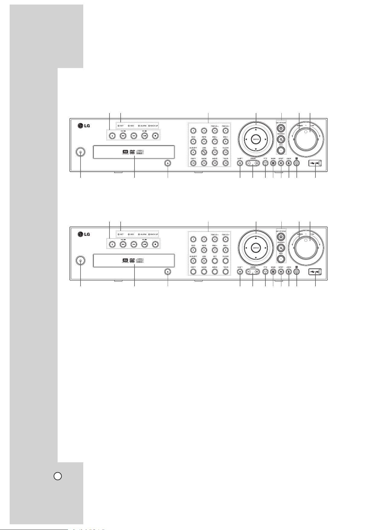
Front Panel
x LE3116D/LE2116D
ab c d e fg
h i
j klmnopq r
x LE3108D/LE2108D
ab c d e fg
h i
a Playback Control Buttons
- X: Pauses playback.
- m/c, .: Search the recorded images in
reverse or skip the recorded images.
- bB: Playback or reverse playback of
recorded images.
- M/C, >: Forward search the recorded
images or skip the recorded images.
- x: Stops playback.
b NET Indicator
Lights when the network is connected.
HDD Indicator
Blinks when the HDD is accessed.
ALARM Indicator
Lights when the alarm out is in progress.
BACK UP Indicator
Lights when the data back up is in progress.
j klmnopq r
c Channel Buttons
You can input a number with channel buttons.
You can also use the channel buttons for subfunction with SHIFT button (11~16 buttons of 8
channel DVR are used for subfunction without
SHIFT button.). The LED in the button indicates
the status as follows:
- Off: The current status is for live mode
Blue: Recording mode.
-
Blinks when an event occurs.
(3) FOCUS - / (4) FOCUS +
Adjusts focus position.
(5) OSD
Accesses or removes the System Control Bar
(OSD).
(6) INFO
Displays or removes system information.
8
Page 9
(7) IRIS - / (8) IRIS +
AAA
AAA
Adjust iris position.
(9) ALM.OFF
Cancels alarm activation and returns the system
to the condition before the alarm was activated.
(10/0) LOG
Displays or removes the System Log List.
(11) SET
Registers the PTZ camera's preset position.
(12) CLEAR
Deletes a memorized preset position.
(13) COPY
Copies the recording data to an external device.
(14) MARK
Sets the mark point for recording search.
(15) MOVE
Moves the camera to the preset position.
(16) TOUR
Tours all registered preset positions in the camera.
d Arrow Buttons (b B v V)
Select or move between the menu options.
ENTER
Confirms menu selections.
e SETUP/ESC
Displays the setup menu or cancels operation
on the setup menus.
SEARCH
Displays the search menu.
REC
Starts or stops instant recording.
f Shuttle Ring
Fast forward or reverse picture search when the
dial is rotated.
g JOG Dial
Allows a forward or reverse frame search.
In pause mode, plays recorded images
frame by frame through rotation. Increases or
decreases the options value.
h 1 Power
Turns DVR on or off.
Press and hold for more than 2 seconds to turn
on or off.
i Disc Tray
Insert a disc here.
j Z (OPEN/CLOSE)
Opens or closes the disc tray.
k SHIFT
If you use the Sub-function of the channel button, the button is activated.
l ZOOM + / -
Zooms in/out on playback window.
m PTZ
Switches this unit to PTZ mode to control the
PTZ camera connected.
n MAIN
Display the MAIN menu to set the screen mode
to full, 4, 6, 8, 9 or 16 screens. Set the video
output signal to VGA mode.
o SPOT
Enter SPOT mode to allow spot monitor control.
p LOCK
Displays the lock menu to change the user type
or disable the system operation.
q Remote Sensor
Point the remote control here.
r USB Port
Connect an external USB device for backup or
playback.
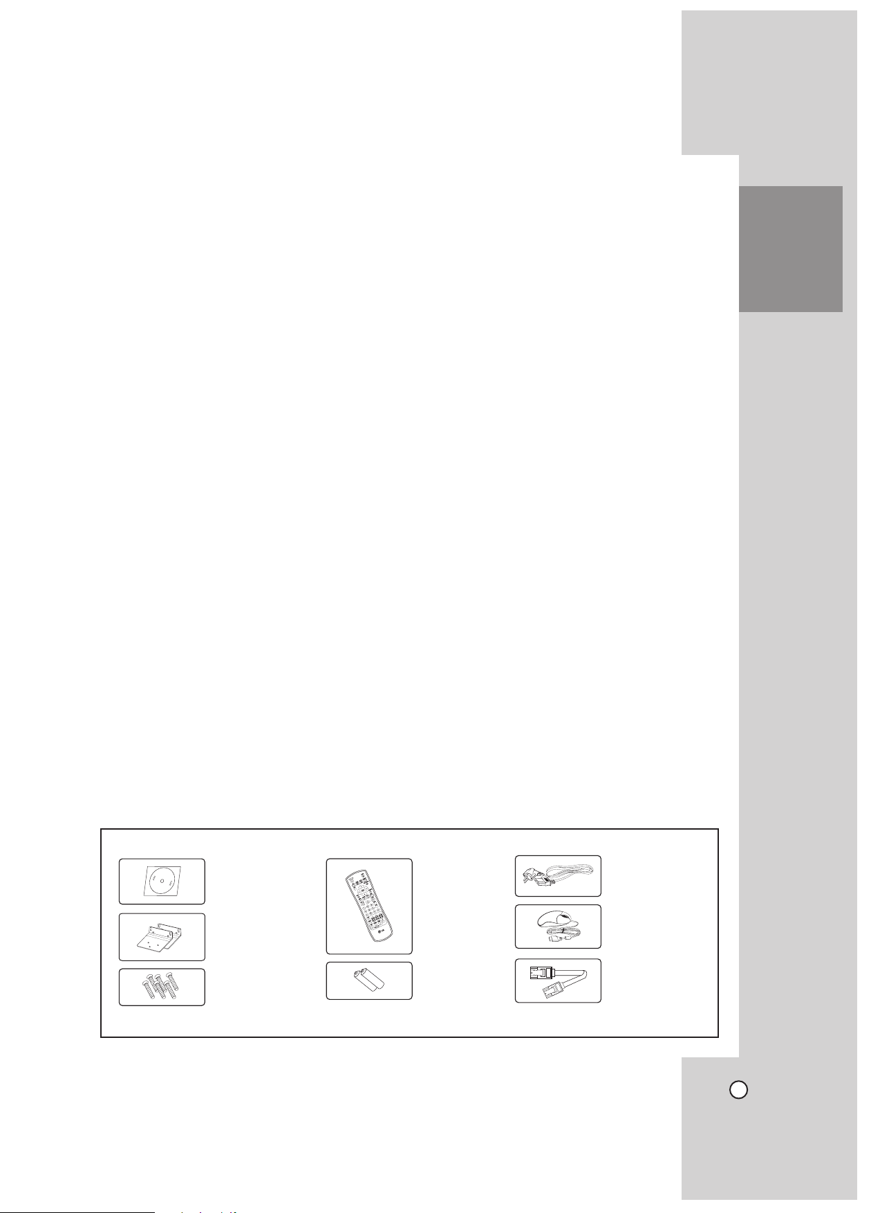
INTRODUCTION
Accessories
Software
Install CD
Remote
Control
Rack Mount
Bracket
Screws
Note: The accessories may be different depending on models.
AAA Type
Battery
Power Plug
Mouse
SATA cable
9
Page 10
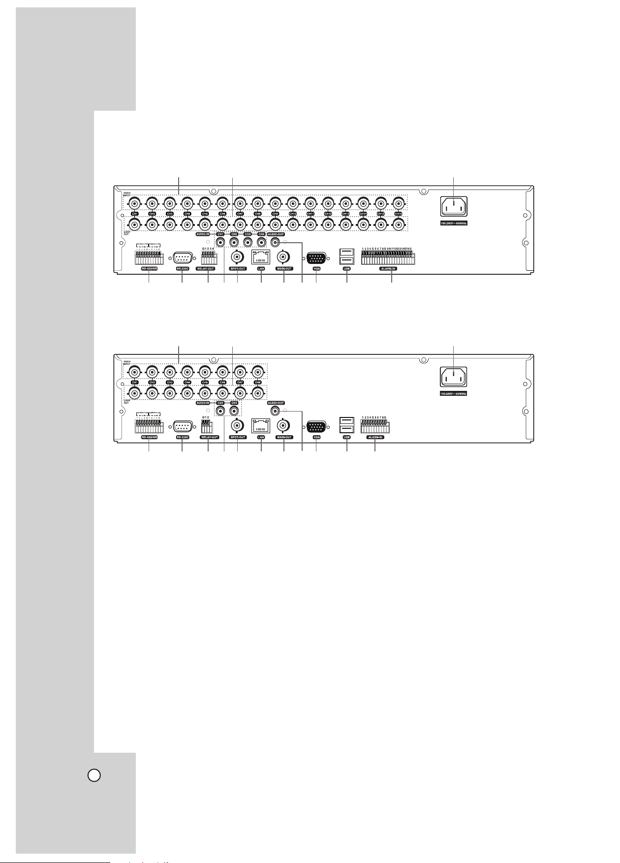
Rear Panel
x LE3116D/LE2116D
a b c
d e fgh ijkl m n
x LE3108D/LE2108D
a b c
d e fgh ijkl m n
a VIDEO INPUT
Connect the camera’s video output to these
BNC connectors.
b LOOP OUT
The signal from VIDEO INPUT connector is
looped out to this connector.
c Power Cord Inlet (AC IN)
Connect the power plug.
d RS-422/485 Terminals
Connect RS422/485 compatible cameras.
Connect the LKD1000 controller to DATA2 terminal.
e RS-232C Connector
Used to connect to a host device equipped with
RS-232C connector (such as a personal computer). This unit can be controlled from other
devices via this connector.
f RELAY-OUT Terminals
Output terminals for alarm(relay) signal.
g
AUDIO INPUT
Connect the audio output of an external device.
h SPOT-OUT (BNC Type Connector)
Connect to spot monitor or display device.
i LAN Port
Connect the ethernet 10/100Mbps network
cable for controlling this unit via a PC network.
j MAIN-OUT (BNC Type Connector)
Connect to main monitor or display device.
k AUDIO OUT
Connect the audio input signal of an external
device.
l VGA
Connect a VGA monitor.
m USB Ports
Connect an optional extension USB device.
n ALARM-IN Terminals
Input terminals for alarm(relay) signal.
10
Page 11

Remote Control
POWER (1)
Turns DVR on or off.
LOCK
Displays the lock menu to change
user type or disable system
operation.
ID
Set the appropriate DVR system
ID to operate via the IR Remote
Controller when using the multiple
DVR.
Press the ID button then press the
number button within 2 seconds to
select the system ID of the DVR.
If you set the system ID to “0”, you
can control multiple DVR at the
same time.
MAIN
Displays the MAIN menu to set
the screen mode to full, 4, 6, 8, 9
or 16 screens.
SPOT
Enter SPOT mode to allow spot
monitor control.
ALM.OFF
Cancels alarm activation and
returns the system to the condition
before the alarm was activated.
OSD
Accesses or removes the system
control bar (OSD).
SETUP/ESC
Displays the setup menu or cancels operation of the setup menu.
Arrow Buttons (b B v V)
Selects or moves between the
menu options.
ENTER
Confirms menu selections.
COPY
Copies the recording data to an
external device.
SEARCH
Displays the search menu.
MARK
Sets the mark point for recording search. You can set the mark
point during the single channel
playback of recorded data.
PAUSE (X)
Pauses playback.
STOP(x)
Stops playback.
REC (z)
Starts or stops recording.
m/c/.
Searches the recorded images
in reverse or skips the recorded
images.
bB
Playback or reverse playback of
recorded images.
M/C/>
Forward searches the recorded
images or skips the recorded
images.
Number Buttons (0,1-9)
To select the PTZ preset number,
ID, or channel.
INFO
Displays or removes the system
information window.
LOG
Displays or removes the System
Log List window.
PTZ
Switches this unit to PTZ mode to
control the connected PTZ camera.
TOUR
Tours all registered preset positions in the camera.
ZOOM + / -
Zooms in/out on the playback
window.
FOCUS + / -
Adjusts the focus of a camera.
IRIS + / -
Adjusts the iris of a camera.
PRESET
SET: Registers the PTZ
camera's preset positions.
CLEAR: Deletes a memorized
preset position.
MOVE: Moves the camera to
the preset position.
F1
This button is not available.
INTRODUCTION
11
Page 12
HOOKUP AND SETTINGS
Precautions
• Depending on the camera and other equipment there are various ways to connect the
unit. Please refer to the camera manual or manuals for other devices as necessary for
additional connection information.
Be sure to switch off the camera before installation and connection.
•
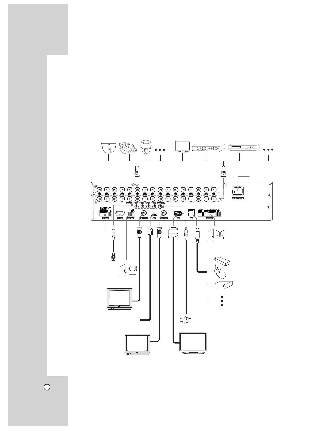
Basic Connection Overview
Connect the coaxial-type cameras
Connect PTZ cameras,
DVRs or keypads
(optional).
Connect audio
(line input)
Connect the alarm (relay)
Connect
BNC type
spot monitor.
Connect the Monitor, DVR, VCR, or others.
Connect
power code
Connect alarm sensors.
Connect mouse
for use with this
operating system
or USB device for
backup, copy or
others.
Connect network cable
for client control.
Connect
BNC type
monitor.
12
For audio amplifier
Connect VGA monitor.
(Default output)
Page 13
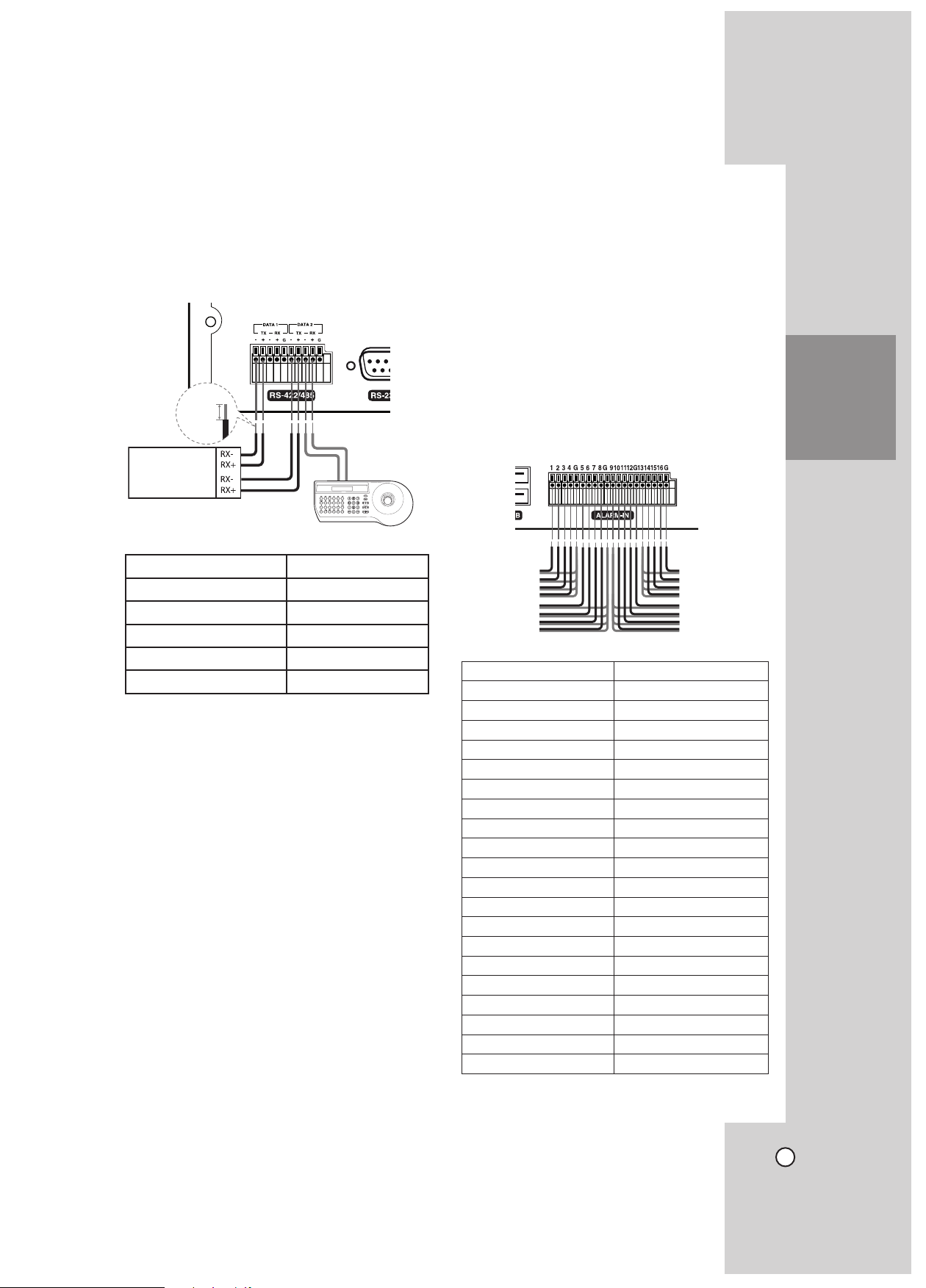
Connecting the RS-422/485
PTZ Units
(RS-422/485 TYPE)
5~7 mm
TX+
TX-
Device
This DVR has two data terminals.
Use this port to connect PTZ cameras, DVRs or keypads (optional).
Connecting Sensor Input and Alarm Output
Alarm terminals are used to connect the alarm devices such as sensors, door switches, etc.
Rear of
the DVR
RS-422/485 Terminal Description
TX - (DATA -) Data Transmission
TX + (DATA +) Data Transmission
RX - (DATA -) Data Reception
RX + (DATA +) Data Reception
GND Shield
Connecting the PTZ camera
Connecting the PTZ serial communication lines to the
RS-422/485 terminal.
Notes:
• When connecting lines, connect the TX - of the
DVR to RX - of the PTZ unit and TX + of the DVR
to RX + (TX +: LG_LS903 protocol only) of the
PTZ unit correctly.
Recommended initial data are 9600 Baud Rate,
•
8 Data bits, 1 Stop bit and No parity.
When connecting PTZ cameras to DVRs it is
•
necessary to set the setup menu for this unit
according to the RS-485 settings of the camera
and DVRs.
Connecting the LKD1000 controller
Connecting the LKD1000 controller to control the
DVR. (Refer to the manuals of the LKD1000 controller for more details.).
Sensor Input
You can connect up to 16 alarm sensors (LE3108/
LE2108: 8 alarm sensors).
Each alarm sensor should be connected with G
(GND). The signal state is adjustable to N/O (Normal
Open) or N/C (Normal Close) through the setup
menu.
Rear of the DVR
Terminal No. Description
1 Sensor Input 1
2 Sensor Input 2
3 Sensor Input 3
4 Sensor Input 4
G Ground
5 Sensor Input 5
6 Sensor Input 6
7 Sensor Input 7
8 Sensor Input 8
G Ground
9 Sensor Input 9
10 Sensor Input 10
11 Sensor Input 11
12 Sensor Input 12
G Ground
13 Sensor Input 13
14 Sensor Input 14
15 Sensor Input 15
16 Sensor Input 16
G Ground
SETTINGS
HOOKUP AND
13
Page 14
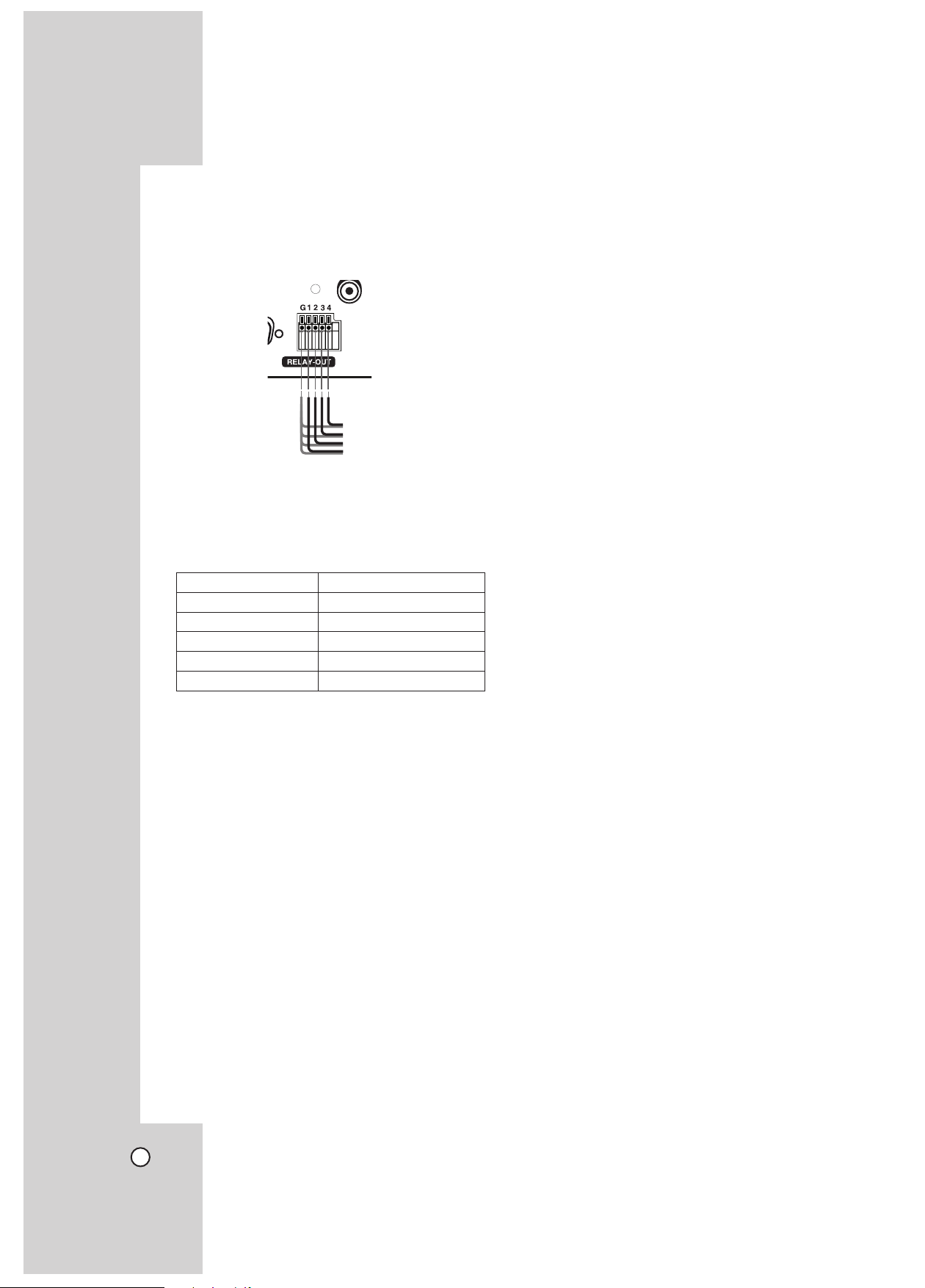
Alarm Output
Connect up to 4 separate alarms (LE3108/LE2108: 2
separate alarms) to the alarm output.
Alarm signal output at an event occurrence.
Rear of the DVR
Note:
The internal switching relays are rated for 0.3A at
125V AC or 1A at 30V DC. If the electric current is
higher than that the unit can be damaged.
Terminal No. Description
G Ground
1 Alarm output 1
2 Alarm output 2
3 Alarm output 3
4 Alarm output 4
Network Connection
LAN Connection
Connect the LAN port to an available 10/100 base-T
port with a straight ethernet cable (not supplied).
The NET indicator on the front panel will be lit.
Automatic Network Configuration
The DVR can automatically obtain and configure the
network interface via DHCP. (see page 33)
Manually Configure Network
The DVR may be manually configured by assigning
an IP address, subnet mask, gateway DNS. (see
page 33)
Connecting the RS-232C Port
The RS-232C is used for communication with a connected PC. This terminal is compliant with the RS232C standard.
Connecting the USB Device
USB Memory Device
Insert the memory device into the USB port. The system automatically recognizes the device.
Using a USB memory device the system S/W can be
easily upgraded.
USB Backup Device
Connect the USB cable of the USB backup device to
the USB port on the rear panel of the unit.
(Example: HDD or other external storage.)
Mouse
Connect the USB mouse for function control of the
unit.
14
Page 15
Concerning the Internal Hard Disk Drive
The internal hard disk drive (HDD) is a fragile piece
of equipment. Please follow the guidelines below
when using the DVR to protect against possible HDD
failure.
We recommend that you back up your important
recordings onto an external backup device in order to
prevent accidental loss.
Make sure that the power is turned OFF when attaching or removing the HDD.
Do not move the DVR while the power is on.
•
• Do not use the DVR in excessively hot or humid
places, or in places that may be subject to sudden
changes in temperature. Sudden changes in temperature can cause condensation to form inside the
DVR. This can be a cause of HDD failure.
While the DVR is switched on, do not unplug from
•
the wall socket or switch the electricity off from the
breaker switch.
If there’s a power failure while the DVR is on there
•
is a chance that some data on the HDD will be lost.
Do not drop the HDD. Also do not put the metallic
•
object such as coins or screwdrivers into the HDD
tray.
When a power failure occurs during recording,
•
avoid adding, replacing or transporting the HDD as
the recorded data may be erased. In this case, turn
the power back on to boot up the unit normally with
the HDD that was being used at the time of the
power failure attached. Then add, replace, or transport the HDD.
The HDD is very delicate. Handle the HDD with
•
care and follow the precautions below because
even a small shock may damage the internal components of the HDD.
Do not place the HDD on a desk or a table
-
directly. Put a thick cushion under the HDD
because even a small shock may damage the
internal components of the HDD.
Do not use an electric screwdriver. Vibrations
-
and shocks caused by an electric screwdriver
may damage the internal components of the
HDD.
When replacing the HDD, do not knock the HDD
-
with other components such as another HDD and
the HDD tray.
Do not knock the HDD with tools such as a driver
-
when replacing the HDD.
Protect the hard disk drives from static electricity.
•
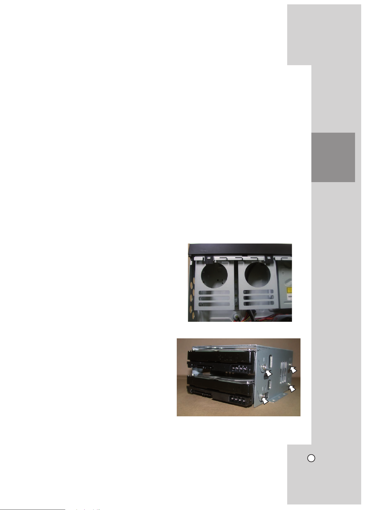
Installing or Replacing the Hard Disk Drive
Installing the Hard Disk Drive
You can install up to 4 HDDs.
However, since the product contains many parts
which may incur electric shocks, accidents or product breakdown, and because improper installation or
setup may disturb HDD recognition or normal product
operation, you should consult with an expert from the
store where the product was purchased.
Turn the power of the unit off and detach the power
plug from the outlet.
Remove the fixing screws on the left/right side
1.
and rear panel.
Detach the top case by sliding it after removing
2.
the screws.
Remove the screws and detach the hard disk
3.
mounting brackets from the unit.
4. Attach the HDD onto the hard disk mounting
brackets with four screws.
SETTINGS
HOOKUP AND
15
Page 16
5. Attach the hard disk mounting brackets with the
screws.
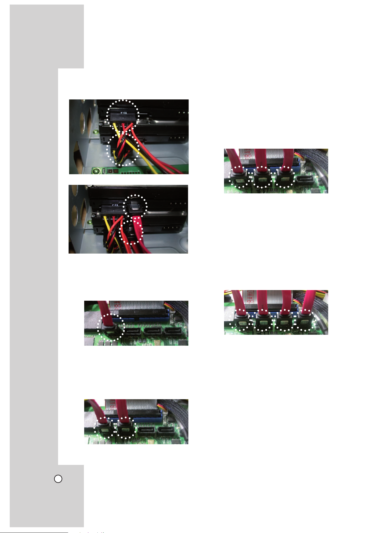
Connect the HDD power cable.
6.
7. Connect the SATA cable.
8. Connect the SATA cable to the SATA connector
on the main board.
When installing 1 HDD.
•
Connect the SATA cable of the HDD to the
first SATA connector. It is use for main system
HDD.
• When installing 3 HDDs.
1. Connect the SATA cable of the first HDD to
the first SATA connector of the main board.
It use for main system HDD.
Connect the SATA cable of the second
2.
HDD to the second SATA connector of the
main board.
Connect the SATA cable of the third HDD
3.
to the third SATA connector of the main
board.
• When installing 4 HDDs.
1. Connect the SATA cable of the first HDD to
the first SATA connector of the main board.
It use for main system HDD.
Connect the SATA cable of the second
2.
HDD to the second SATA connector of the
main board.
Connect the SATA cable of the third HDD
3.
to the third SATA connector of the main
board.
Connect the SATA cable of the fourth HDD
4.
to the fourth SATA connector of the main
board.
9. Assemble the top case.
• When installing 2 HDDs.
1. Connect the SATA cable of the first HDD to
the first SATA connector of the main board.
10. Fix the screws.
11. After installing the HDD, you must format the
HDD using the setup menu (See page 38).
It use for main system HDD.
Connect the SATA cable of the second
2.
HDD to the second SATA connector of the
main board.
Notes:
When you add the new HDD, do not change the
•
position of the HDD. It may delete the current
data and cause a malfunction.
You should install one of the HDDs on the first
•
connector of the main board. If you do not install
the HDD on the first connector of the main board,
the DVR will not work properly.
16
Page 17

Replacing the Hard Disk Drive
Turn the power of the unit off and detach the power
plug from the outlet.
Follow steps 1-3 described in “Installing the Hard
1.
Disk Drive”.
Remove the connector from the HDD.
2.
Recommended HDD
The following HDD has been tested and compatibility
is ensured. When you attach multiple HDDs use the
recommended HDDs.
Note:
If you do not use the recommended HDD, the system
may not be operated normally.
Maker RPM Capacity Interface Model No.
7,200 250 GB SATA ST3250311SV
3. Remove the screws from the hard disk drive on
the left/right side of the hard disk the mounting
bracket.
Seagate
Hitachi 5,700 1 TB SATA HCS5C1010CLA382
7,200 500 GB SATA ST3500410SV
5,400 1 TB SATA ST31000424CS
SETTINGS
HOOKUP AND
4. Remove the HDD from the hard disk mounting
bracket.
Install the new HDD in the reverse order to when
5.
replacing the hard disk drive.
After replacing the hard disk drive, insert the
6.
power plug into the outlet and turn the power of
the unit on.
Notes:
Make sure that each of the SATA cables is con-
•
nected to the connector housing through its holes.
Do not stack them nor keep them upright.
•
• Do not use an electric screwdriver to fix them.
17
Page 18

System Operation
1. Press and hold 1 (POWER) button until the beep
sounds to turn on the unit. System booting will
commence. The LG logo image will be displayed
on the main monitor during the system booting.
2. When the booting is completed the live window
will be displayed. Click the LOCK button on the
system control bar or press the LOCK button on
the remote control to display the log-in window.
3. Select
Enter the password by using the virtual keyboard.
4.
Press LOCK or click the OK(LOCK) icon.
5.
a user name by using the mouse or arrow
and the ENTER button on the remote control or
front panel.
- ADMINISTRATOR: Unlimited operation of the
unit.
Power User: Use of the limited functions of the
-
system. (The setup configuration is not
allowed to change.)
Normal User: Use of the limited functions of
-
the system. (Split monitor and live image view
are available.)
(Initial password is “000000”.)
You can see the live screen and operate the system.
User access rights
•
User Level Administrator
View
Live Video
Alarm Off YES YES NO
PTZ YES YES NO
Instant Record YES YES NO
Export YES YES NO
Search/Play YES YES NO
Setup YES NO NO
Shut Down YES NO NO
YES YES YES
Power
User
Normal
User
System Shutdown
1. First, you must stop playback and exit the setup
menu.
In playback, press STOP.
Press and hold 1 (POWER) button until the beep
2.
sounds and the logout window will be displayed.
3. Enter the password by using the virtual keyboard.
4. Press LOCK or click the OK(LOCK) icon.
The system will shutdown.
Notes:
You are not allowed to connect the VGA moni-
•
tor and the composite monitor simultaneously.
Consequently, the user is obliged to choose either
the composite monitor or the VGA monitor. When
set to composite monitor there is no VGA output.
When set to VGA monitor there is no composite
output. SPOT-OUT is unaffected by the monitor
setting.
This DVR is based on a VGA monitor using OSD.
•
We recommend to using the VGA monitor with
this unit. If you use a composite monitor, the OSD
quality may lower to read it.
18
Page 19
Selecting the main monitor type
You can select the main monitor type to display the
main screen on the power on condition.
Using the VGA Monitor
1. Connect the VGA monitor to the VGA jack on the
rear of the DVR.
Turn on the VGA monitor.
2.
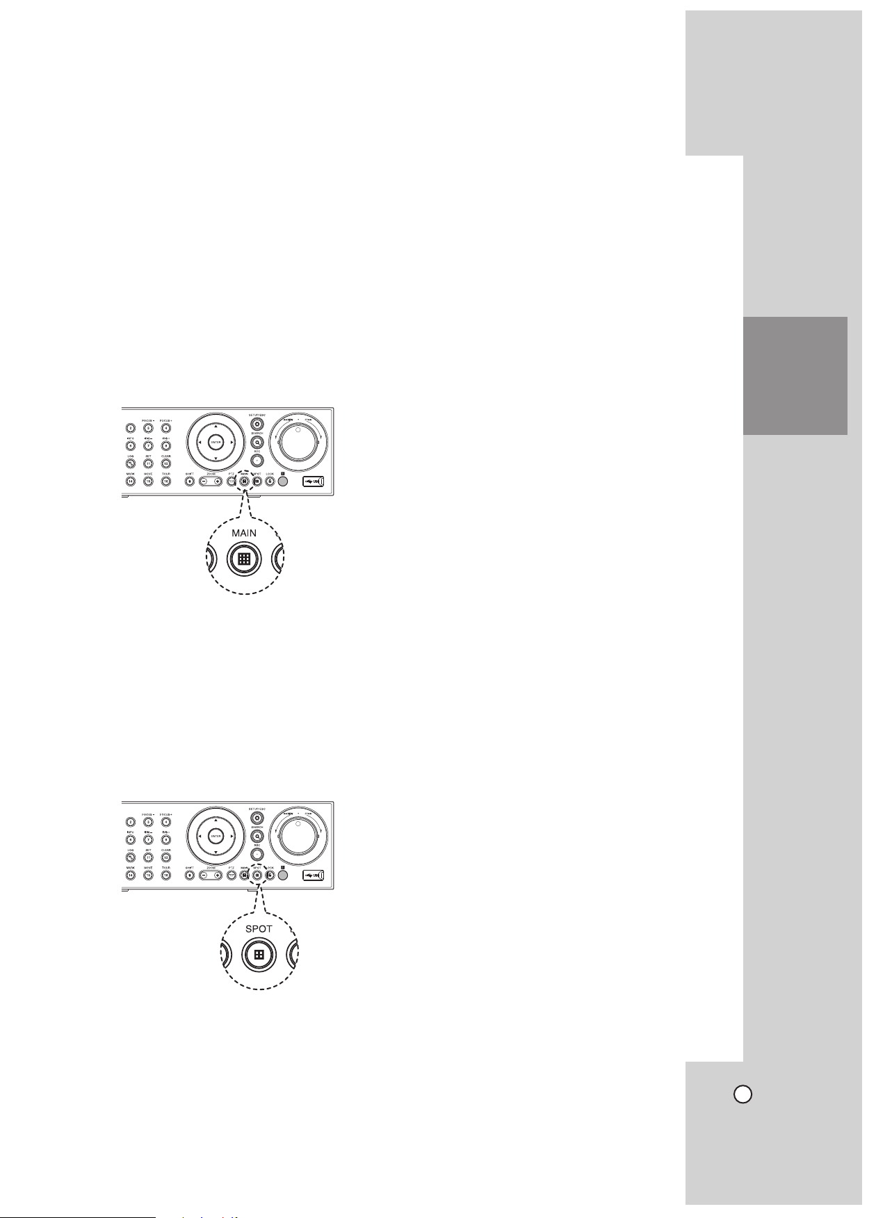
3. Press and hold the MAIN button on the front
panel until the beep sounds to display the main
screen. The DVR will restart and then the VGA
monitor is set as a main monitor.
Note:
You can select the monitor type by using the MAIN or
SPOT button at anytime. If you change the monitor
type, the system will be rebooted automatically.
SETTINGS
HOOKUP AND
CCTV (Composite Video Type) Monitor
1. Connect the CCTV monitor to the MAIN-OUT jack
on the rear of the DVR.
2. Turn on the CCTV monitor.
3. Press and hold the SPOT button on the front
panel until the beep sounds to display the main
screen. The DVR will restart and then the CCTV
monitor is set as a main monitor.
19
Page 20
General Explanation of the Live Screen on the Main Monitor
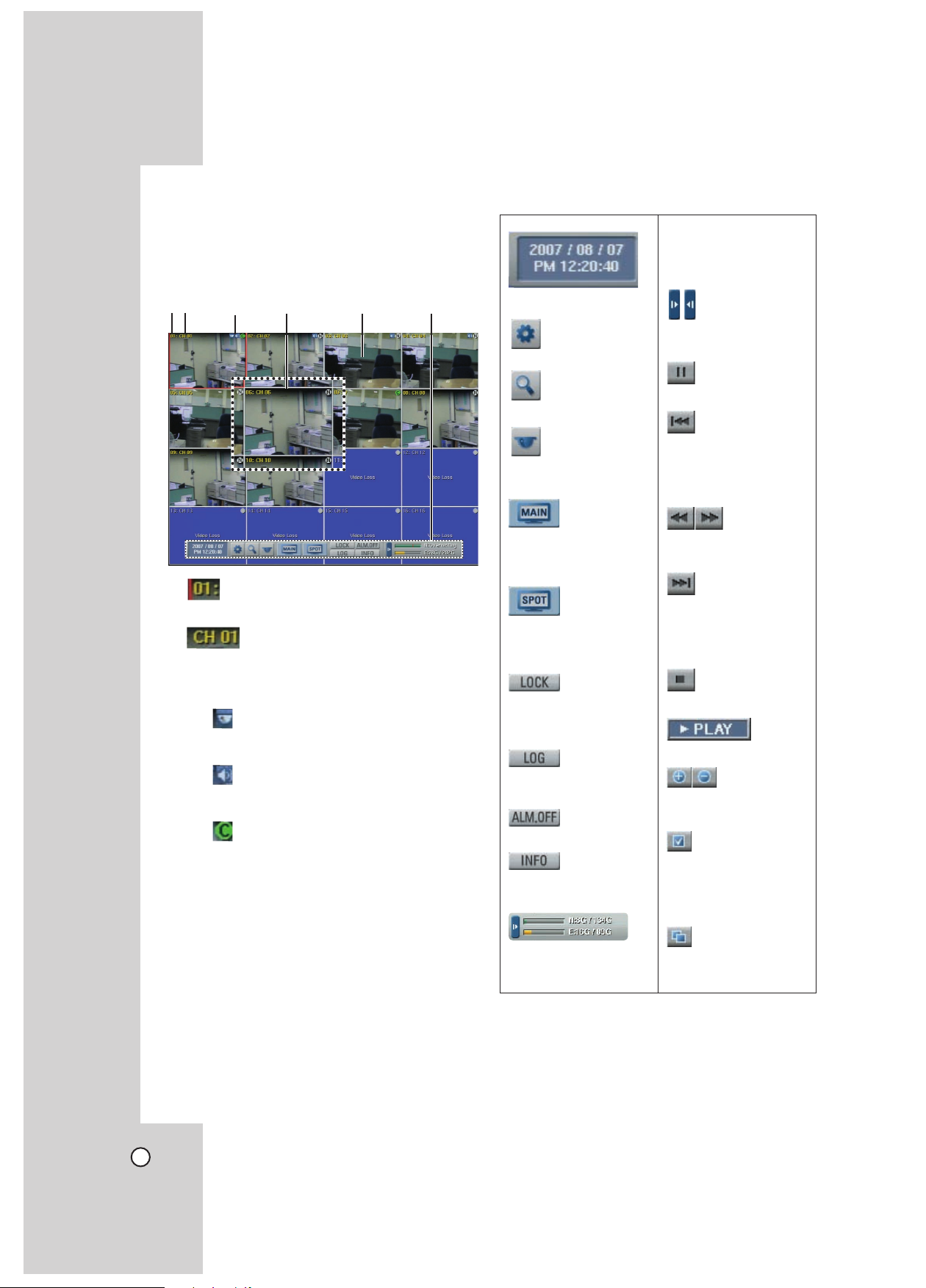
Main Monitor Screen
ab c d e f
fSystem Control Bar
Displays the current date
and time.
Displays the setup menu.
Displays the search menu.
Displays the PTZ
remote control window.
- N (Normal partition):
Used size/total size.
- E (Event partition):
Used size/total size.
Display/hide playback
control bar.
Pause playback.
Jump to the beginning
of the current data
recorded on the same
date.
a Channel Number
Displays the channel number.
b Channel Name
Displays the edited channel name.
cCamera Status Icon
PTZ camera icon
•
Displays the PTZ camera status.
Input audio icon
•
Displays the input audio status.
Recording status icon
•
Displays the recording status.
- Green “C” indicates continuous recording.
- Green “I” indicates Instant recording.
- Red “S” indicates sensor triggered
recording.
Blue “M” indicates motion detection
-
recording.
White “N” indicates the channel is not
-
being recorded.
Displays the screen division selection window for
the main monitor.
Displays the screen division selection window for
the spot monitor.
Displays the lock menu to
change the user type or
disable system operation.
Displays the system log
list window.
Turns the alarm off.
Displays the system
information window.
Displays the remaining
HDD status.
Select the required
scanning speed.
Jump to the last minute of the current data
recorded on the same
date.
Stop playback.
Display playback status.
Enlarge/reduce the
playback window.
Click at a desired point
to be marked during
playback. Up to 15
points can be marked.
Display copy(export)
menu.
dSelected Channel
Displays the selected channel with red box.
eLive Screen
Displays the current surveillance live screen.
20
Note:
Use OSD with the SHIFT button on the front panel
or click the right button on the mouse to display /
remove the system control bar displayed on-screen.
Page 21

Selecting Live Screen Mode
Main Monitor
You can select the live screen mode to display a full,
4-split, 6-split, 8-split, 9-split or 16-split screens on
the main monitor.
1. Press MAIN or click the MAIN icon in the system
control bar.
Screen mode select menu of main monitor is displayed on the main monitor.
Select screen mode.
2.
Selected Main Channel
Screen mode
Selected split
mode
Sequence
Spot Monitor
You can select the live screen mode to full or 4-split
screens on the spot monitor.
Press SPOT or Click the SPOT icon in the system
1.
control bar.
Screen mode select menu of spot monitor is displayed on the main monitor.
Select screen mode.
2.
Selected spot channel
Selected split
mode
Screen mode
Sequence
Channel buttons
SETTINGS
HOOKUP AND
Channel Buttons
- Channel Number: Press the 1 to 16 channel
button to see the current surveillance images
in selected live screens on the main monitor.
-
Full Screen Mode: When you see the selected
channel on the full screen.
4, 6, 8, 9 and 16 Split Mode: Displays select-
-
ed split screens on the main monitor.
Sequence: View all channels in sequence.
-
Select [OK (MAIN)] and press ENTER to confirm
3.
your selection.
Note:
To display the screen you desire to watch in full
screen mode, double click the desired channel.
- Channel Number: Press the 1 to 16 channel button to see the current surveillance image on the
spot monitor.
-
Full Screen Mode: When you see the selected
channel on the full screen.
4 Split Mode: Displays 4 split screens on the
-
spot monitor.
Sequence: Views the all channels in sequence.
-
Select [OK (SPOT)] and press ENTER to confirm
3.
your selection.
21
Page 22
PTZ Camera Control
You can control the cameras connected via the data
port of RS-422/485 terminal. You must set the configuration between the PTZ camera and the DVR.
1. Select the PTZ camera channel on the main monitor you want to control.
Press PTZ or Click the PTZ icon in the system
2.
control bar.
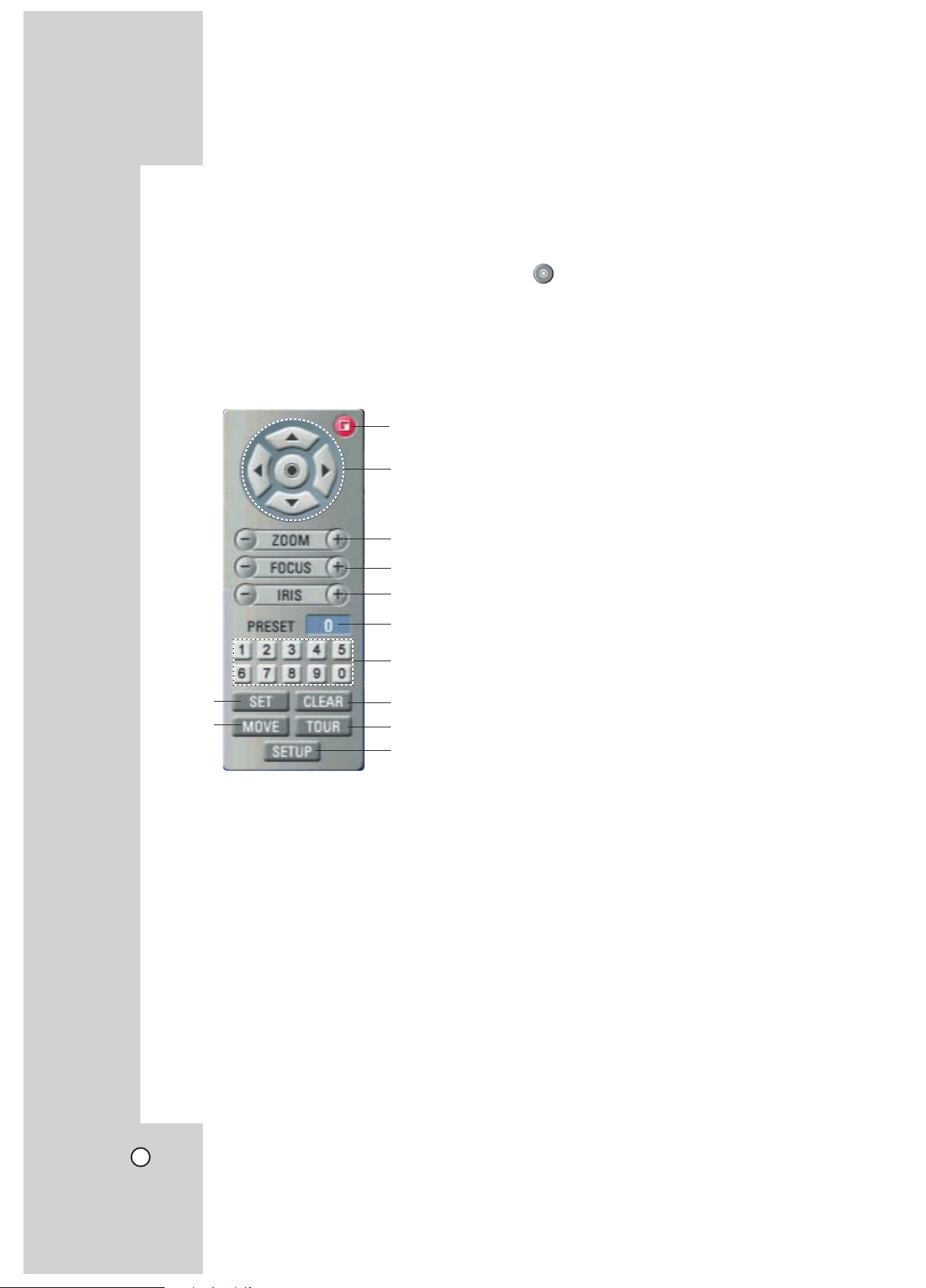
Virtual PTZ remote control is displayed on the
main monitor.
Use each item to control the PTZ camera.
3.
a
b
c
d
e
f
g
a Exit
Remove the PTZ virtual remote control.
b v/V/b/B
Use to pan/tilt the camera.
Confirm the preset position.
c ZOOM + / -
To adjust the camera zoom.
dFOCUS + / -
To manually adjust the focus of a camera.
eIRIS + / -
To manually adjust the iris of a camera.
fDisplays the Selected Preset Number
gNumber Buttons
To input the preset number.
hSET
To register preset positions.
iMOVE
To move the camera to the preset position.
jCLEAR
To delete a memorized preset position.
kTOUR
To start a preset tour.
lSETUP
To displays the setup menu of the PTZ camera.
h
i
j
k
l
22
Page 23

Preset Settings
Preset position is the function to register camera
monitoring positions (preset positions) associated
with position numbers.
By entering the position numbers, you can move
cameras to the preset positions.
Note:
To activate this function, you need to register the
preset positions of the PTZ cameras.
To Register Preset Positions
1. Move the camera to a point you wish by using the
v/V/b/B.
2. Press SET or click the [SET] icon.
3. Select the preset number you wish to register.
4. Press ENTER or click the [
The position and its number are memorized.
5. Repeat steps 1-4 to add additional positions.
Note:
Preset numbers from 0 to 255 are available on this
unit but the actual preset range differs depending on
PTZ cameras.
] icon.
Changing to a Picture in a Preset
Position
The following function is available only with cameras
provided with the preset function.
The preset function makes the combination camera
move to the programmed preset position.
It is necessary to program preset positions for the
combination camera beforehand.
Press the MOVE button or click the [MOVE] icon.
1.
2. Use number buttons to enter the memorized preset position’s index number then press ENTER or
click the [
set position and the picture of the camera in that
position appears on the monitor.
] icon. The camera moves to the pre-
To Tour The Preset Positions
You can tour all preset positions.
1. Press the TOUR button or Click the [TOUR] icon.
All registered preset positions in the camera will
be selected and the camera position image will be
switched on the active monitor.
You can stop the tour by pressing the TOUR
2.
button or clicking the [TOUR] icon.
Setup for PTZ Cameras
You can adapt the camera to your requirements by
setting up the respective items in menus.
1. Click the [SETUP] icon.
The setup menu appears in the selected window
of the main monitor.
Use arrows, ZOOM +/- and ENTER buttons to set
2.
the options.
Notes:
Refer to the manuals of the PTZ camera for more
•
details.
Some PTZ cameras may not operated correctly
•
with this unit.
You cannot control the other functions when the
•
PTZ virtual remote control is displayed.
SETTINGS
HOOKUP AND
To Clear the Preset Position
You can clear a memorized preset position.
1. Press the CLEAR button or Click the [CLEAR]
icon.
Use number buttons to enter the memorized pre-
2.
set index number then press ENTER or Click the
] icon to clear the preset positions.
[
Note:
This function may not be available depending on PTZ
cameras.
23
Page 24

Viewing System Information
To view system information:
1. Press INFO or click the INFO icon in the system
control bar.
The system information window is displayed on
the main monitor.
Press INFO or click the [Exit(Info)] button to exit
2.
the window.
Viewing the System Log List
To view the system log list:
1. Press LOG or click the LOG icon in the system
control bar.
The system log list window is displayed on the
main monitor.
Use b / B to see the previous or next log list.
2.
3.
Press LOG or click the [Exit(LOG)] button to exit
the window.
Note:
The system log list.
No. Log Message
1 Power On
2 Power Off
3 Power Recovery
4 Admin Login (Remote)
5 Admin Logout (Remote)
6 Power User Login (Remote)
7 Power User Logout (Remote)
8 Normal User Login (Remote)
9 Normal User Logout (Remote)
10 Admin Login (Local)
11 Admin Logout (Local)
12 Power User Login (Local)
13 Power User Logout (Local)
14 Normal User Login (Local)
15 Normal User Logout (Local)
16 Configuration Changed
17 Configuration Imported
18 Factory Default Set
19 Backup Started
20 Backup Finished
21 Backup Failed
22 Export Started
23 Export Finished
24 Export Failed
25 S/W Updated
26 HDD Added (HDD1)
27 HDD Added (HDD2)
28 HDD Added (HDD3)
29 HDD Added (HDD4)
30 HDD Removed (HDD1)
31 HDD Removed (HDD2)
32 HDD Removed (HDD3)
33 HDD Removed (HDD4)
34 HDD Formatted (HDD1)
35 HDD Formatted (HDD2)
36 HDD Formatted (HDD3)
37 HDD Formatted (HDD4)
38 HDD Changed (HDD1)
39 HDD Changed (HDD2)
40 HDD Changed (HDD3)
41 HDD Changed (HDD4)
42 HDD Damaged (HDD1)
43 HDD Damaged (HDD2)
44 HDD Damaged (HDD3)
45 HDD Damaged (HDD4)
46 System Fan Failure
24
Page 25

Menu Configuration
The features and options of the DVR are configured
through the menu.
The operations of this unit can be set via a menu
displayed on the main monitor. You can select and
set the operational conditions by using the buttons on
the front panel and the remote control or using a USB
Mouse connected to the unit.
Title tab
First
level
Second
level
Help menu
Using a Mouse to Set a Menu
Use the left and right mouse buttons to set the menu.
• Left button: Use to select a required item or
decrease the options value.
Right button: Use to increase the options value.
•
Click the
1.
on-screen display with the left mouse button to
display a setup menu.
Click the desired option with the left mouse button
2.
to move to the second or third level.
Click the desired option with the left mouse but-
3.
ton.
Set the selected options value.
4.
5. Click the Exit icon to exit setup menu.
If the save message appears, click [OK] with the
left mouse button to save the settings.
icon on the bottom of the
Third
level
Setting the Menu Using the Front Panel
Buttons or Remote Control Buttons
Arrow Buttons:
Use these buttons to select the menu options or
adjust the options value.
ENTER:
Select the option or confirm the setting.
ESC:
Return to the previous menu or level.
Press SETUP/ESC to display the setup menu.
1.
Use v / V to select the desired option.
2.
While the desired item is selected, press ENTER
3.
to move to the second level.
Use v / V to select the desired option then press
4.
ENTER to move to the third level.
Use v / V / b / B to select the desired option
5.
then press ENTER to set the value.
Use b / B to select the desired setting then press
6.
ENTER to confirm your selection.
Press SETUP/ESC to exit the Setup menu.
7.
If the save message appears, press ENTER to
save the settings.
Notes:
When you operate the function menu by using the
•
remote control and front panel buttons, both
buttons are operated in the same way to control the
function menu.
To use other functions of number buttons on the
•
front panel as shown below.
Press SHIFT.
1.
The button indicator turns blue.
Select the function button you want.
2.
• All the operation explanations are based on
using the remote control.
SETTINGS
HOOKUP AND
25
Page 26

Camera Settings
Camera
The channel name, covert and input audio channel
settings are configured.
l Ch: Displays the channel number.
l Name: Enter the channel name using up to 12
characters.
- b/B/v/V: Select a character.
- ENTER: Confirms your selection.
- ESC: Exits the virtual keyboard menu.
l Covert: You can set the camera conditions to
prevent operation by other users. If the covert
option is set to ON, “LG logo” is displayed on the
live window with POWER or NORMAL user.
l Audio: You can hear from the selected input audio
channel.
Video Adjustment
Adjust the brightness, contrast and color settings
of each camera channel. You can see the settings
screen from the preview windows.
PTZ
Settings for the PTZ cameras connected via the data
port of the RS-422/485 terminal.
l Channel: Selects the desired channel to set the
connected PTZ camera.
l Port: Selects the connected data port of the
RS-422/485 terminal on the rear panel. The DATA
2 port is used to control the PTZ camera connected
to DVR or to control by using the LKD1000 controller. If you want to use the PTZ camera via DATA
2 port, you should set the DVR ID to NONE on
the system setup menu. If you use the LKD1000
controller to control the DVR via DATA 2 port, you
should set the DVR ID number(1~16) on the system setup menu.
l Control ID: Selects the PTZ camera ID from 00 to
255. Make the same settings as the PTZ camera.
l Protocol: Selects the protocol supported by PTZ
camera.
l Baud Rate: Selects the communication speed.
(1200, 2400, 4800, 9600, 19200, 38400, 57600 or
115200)
l PTZ Test: After the PTZ setting, you can test the
pan/tilt function for the selected PTZ camera. You
can see the test screen from the preview windows
on the right side of the PTZ test option.
- b / B: Test the pan direction.
- v / V: Test the tilt direction.
Note:
The supported PTZ camera list is on page 69 for
reference.
l Channel: Selects the desired channel to adjust.
l Brightness: Adjust the brightness value from 0 to
100 for the selected channel.
l Contrast: Adjust the contrast value from 0 to 100
for the selected channel.
l Color: Adjust the color value from 0 to 100 for the
selected channel.
26
Page 27

Recording
Settings concerning normal recording.
l Ch: Displays the channel number.
l Resolution: Selects the recording resolution.
l Quality: Selects the recording picture quality
(LOWEST, LOW, STANDARD, HIGH or
HIGHEST).
l Frame Rate: Selects the frame rate. The frame
rate is the number of recorded frames per second.
According to resolution, the frame rate is set
automatically. If you wish to set manually, refer to
the below.
-
LE3116D/LE3108D model
Resolution Frame Rate
352*240 1, 3, 5, 7.5, 15, 20, 30
NTSC
PAL
-
LE2116D/LE2108D model
NTSC
PAL
l Prealarm: Specify the pre-event recording time that
records the situation until the sensor alarm signal
has input or motion has been detected. (OFF, 5,
10, 20, 30, 40, 50 or 60 SEC)
l Postalarm: Specify the post-event recording time
that records the situation from when the sensor
alarm signal has input or motion has been detected. (10, 20, 30, 40, 50 SEC or 1, 2, 3, 5, 10 MIN)
704*240 1, 3, 5, 7.5, 15
704*480 1, 3, 5, 7.5
352*288 1, 3, 5, 6, 12.5, 20, 25
704*288 1, 3, 5, 6, 12.5
704*576 1, 3, 5, 6
Resolution Frame Rate
352*240 1, 3, 5, 7.5, 15
704*240 1, 3, 5, 7.5
704*480 1, 3
352*288 1, 3, 5, 6, 12.5
704*288 1, 3, 5, 6
704*576 1, 3
Note:
The setting values of Prealarm and Postalarm
options are also used as the same ones for Sensor
Recording and Motion Recording function.
Sensor Recording
Settings concerning sensor recording.
l Ch: Displays the channel number.
l Resolution: Selects the recording resolution.
l Quality: Selects the recording picture quality
(LOWEST, LOW, STANDARD, HIGH or
HIGHEST).
l Frame Rate: Selects the frame rate. The frame
rate is the number of recorded frames per second.
According to resolution, the frame rate is set
automatically. If you wish to set manually, refer to
the below.
LE3116D/LE3108D model
-
Resolution Frame Rate
352*240 1, 3, 5, 7.5, 15, 20, 30
NTSC
PAL
LE2116D/LE2108D model
-
NTSC
PAL
704*240 1, 3, 5, 7.5, 15
704*480 1, 3, 5, 7.5
352*288 1, 3, 5, 6, 12.5, 20, 25
704*288 1, 3, 5, 6, 12.5
704*576 1, 3, 5, 6
Resolution Frame Rate
352*240 1, 3, 5, 7.5, 15
704*240 1, 3, 5, 7.5
704*480 1, 3
352*288 1, 3, 5, 6, 12.5
704*288 1, 3, 5, 6
704*576 1, 3
SETTINGS
HOOKUP AND
27
Page 28

Motion Recording
Settings concerning motion recording.
l Ch: Displays the channel number.
l Resolution: Selects the recording resolution.
l Quality: Selects the recording picture quality
(LOWEST, LOW, STANDARD, HIGH or
HIGHEST).
l Frame Rate: Selects the frame rate. The frame
rate is the number of recorded frames per second.
According to resolution, the frame rate is set
automatically. If you wish to set manually, refer to
the below.
LE3116D/LE3108D model
Resolution Frame Rate
352*240 1, 3, 5, 7.5, 15, 20, 30
NTSC
PAL
-
LE2116D/LE2108D model
NTSC
PAL
704*240 1, 3, 5, 7.5, 15
704*480 1, 3, 5, 7.5
352*288 1, 3, 5, 6, 12.5, 20, 25
704*288 1, 3, 5, 6, 12.5
704*576 1, 3, 5, 6
Resolution Frame Rate
352*240 1, 3, 5, 7.5, 15
704*240 1, 3, 5, 7.5
704*480 1, 3
352*288 1, 3, 5, 6, 12.5
704*288 1, 3, 5, 6
704*576 1, 3
Video
Selects the video format to NTSC or PAL according
to your video system format.
Select the video format.
1.
The confirmation message is displayed.
Select [OK] and press ENTER.
2.
the HDD has been formatted, the system will
After
reboot.
Schedule Settings
The DVR can record according to a schedule set
by the user. It can also record manually regardless of date and time. The recording can be made
either continuously or triggered by events (alarm and
motion detection).
The recording schedule screen displays one day of
the week showing the schedule of all channels over a
24-hour period.
For each 1-hour cell block the recording method can
be specified. The recording method for each block is
shown in color for easy viewing.
Time line
Channel
numbers
1-hour
cell block
Recording mode
28
Page 29

To Set the Recording Schedule for a
Typical Day of the Week
1. Select a day of the week.
(Sun, Mon, Tus, Wed, Thu, Fri or Sat)
2. Select the desired channel to schedule recording.
3. Select the time cell block for the start time.
- Green+Blue
ing): Recording starts automatically from the
preset time. When the motion is detected
within a designated time, change the continuous recording mode to motion event recording
mode and recording starts automatically.
- Green+Yellow
event recording): Recording starts automatically from the preset time. When the sensor
alarm signal has input or motion has been
detected, change the continuous recording
mode to motion event recording mode and
recording starts automatically.
Select the next time cell block of schedule time
5.
cell blocks to confirm the schedule time.
(Continuous+Motion event record-
(Continuous+Sensor+Motion
SETTINGS
HOOKUP AND
4. Press ENTER or click the left mouse button to
select a recording mode. The color of the cell
blocks will change automatically.
- Gray:
- Green (Continuous recording): Recording starts
Red (Sensor event recording): Recording starts
-
Blue (Motion event recording): Recording starts
-
- Yellow
- Green+Red
No scheduled recording
automatically from the preset time.
automatically when the sensor alarm is occurs
within a designated time.
automatically when motion is detected within a
designated time.
(Sensor+Motion recording): Recording
starts automatically when the sensor alarm
signal has input or motion has been detected.
(Continuous+Sensor event recording): Recording starts automatically from the
preset time. When the sensor alarm occurs
within a designated time, change the continuous recording mode to sensor event recording
mode and recording starts automatically.
6. Press ENTER or click the left mouse button
repeatedly to select gray to set the time for the
end of the schedule. The settings cell block is
highlighted.
7. Press SETUP/ESC to move to the previous menu.
• ENTER: Confirm the selection.
• Press ESC to exit the specific date selection
menu.
29
Page 30

To Set a Recording
Schedule for a Special Day
In addition to the weekly schedule, up to 10 specific
date/time periods can be defined. To configure the
specific recording schedule select Specific Dates.
1. Select the [Special Day] option.
2. Select a cell block.
b / B (or left/right mouse button): Changes
•
the value at the current position.
5.
Use b / B / v / V to select [OK] button and
press ENTER.
The virtual keyboard menu appears.
6. Enter the name of the special day. Use v/V/b/B
to select a character then press ENTER to confirm your selection.
7. Use v / V to select the [OK] icon then press
ENTER to fix the date of the special day and
return to the special day menu screen.
Select the schedule time and set the recording
8.
method for each channel.
3. Press the ZOOM + button or click the [Add] icon
on the special day setting menu.
The specific date selection menu appears.
4. Enter the necessary information for year, month
and date.
• b / B / v / V: Press to move the columns,
[OK] or [Cancel] buttons.
Checking the Special Day Schedule List
1. Press INFO when the “Special Day” option is
selected.
The special day scheduled list appears.
2. Select a special day title on the list and press
ENTER.
The title color turns orange.
3. Select
Press ESC to exit the special day schedule list.
4.
the [Edit] icon then press ENTER to edit
the special day or press ZOOM - to delete the
special day schedule.
30
Page 31

Note:
If the special day recording schedule is duplicated
with the other recordings, only the special day recording is possible.
Copying the Recording Schedule
Copying from the Scheduled Data of the Channel
You can copy the schedule data of the channel to the
other channel(s) within the selected day of the week.
Select the day of the week and press ENTER.
1.
2. Select channel that you want to copy.
3. Press COPY then the channel selection menu
appears.
4. Use b / B to move to the left or right column then
press ENTER to select the target channel(s).
You can cancel the selected channel by pressing
ENTER.
Use v / V to select [OK] then press ENTER to
5.
confirm your selection.
Display Settings
OSD
l Language: Select a language for the setup menu
and information display.
l Channel Name
- ON: Displays the title of the channel.
- OFF: Displays the live picture without the title of
the channel.
l Channel Status
- ON: The current channel recording status is
displayed.
OFF: Remove the current channel recording sta-
tus.
SETTINGS
HOOKUP AND
Copying from the Scheduled Data of the Day
You can copy the scheduled day of the week to
another day of the week, weekday and weekend
using the COPY button.
Select the day of week that you want to copy.
1.
2. Press COPY then the select date(s) menu appears.
3. Use b / B to select the target date(s).
4. Use v / V to select [OK] then press ENTER to
confirm your selection.
Main Monitor
l Dwell Time: You can set the channel sequence
time to 2 SEC, 5 SEC, 10 SEC, 20 SEC, 30 SEC,
40 SEC, 50 SEC, 60 SEC, 70 SEC, 80 SEC or 90
SEC.
31
Page 32

Spot Monitor
l Dwell Time: You can set the channel sequence
time to 2 SEC, 5 SEC, 10 SEC, 20 SEC, 30 SEC,
40 SEC, 50 SEC, 60 SEC, 70 SEC, 80 SEC or 90
SEC.
l Event Popup: Displays an event popup on the
spot monitor if motion, sensor or all (motion or sensor) occur.
l Covert Camera:
- ON: If you set to ON, the covert channel(s)
is(are) not displayed on the spot monitor .
OFF: The covert channel(s) is(are) not displayed
on the spot monitor with power and normal
user. View the all channels with Administrator
user.
Event Settings
Sensor
l In: Displays the number of the ALARM-IN terminal.
l Sensor Type: The sensor state can be set to
either N.O. (Normally Open) or N.C. (Normally
Closed).
l Camera: Select the connected camera channel to
the ALARM-IN terminal.
l Relay Output: Select the alarm (relay) output
number for the RELAY-OUT terminal for the output
alarm (relay) signal.
l Preset: Select the preset number. When the input
is activated, the camera moves to the selected preset position and the picture of the camera in that
position appears on the monitor.
Motion
l Channel: Select the channel to set motion detec-
tion.
l Sensitivity: Set the level of sensitivity for the cre-
ated motion detection area. Sensitivity can be set
from level 01 to 10 or OFF.
l Relay Output: Select the number of the RELAY-
OUT terminal for the output alarm (relay) signal
when motion is detected.
l Area: Select the desired motion detection area on
the preview window screen.
- b / B / v / V: Moves the yellow cell box to
another cell zone.
ENTER: Selects or cancels the motion
detection area at the current cell position.
Press ESC to exit the settings.
-
Notes:
You can select the motion detection area by using
•
the mouse.
To select the area: Drag & drop a cell to the
-
right to select the motion detection area.
To cancel area: Drag & drop a cell point of
-
a selected cell area to the left to cancel the
motion detection area.
In the condition that illumination is low and the
•
outline of object is not clear enough to see,
regardless of sensitivity, Motion Event could be
possible not to happen. You must check Motion
Event before setting.
32
Page 33

Output
l Relay Off
- MANUAL: Use the ALM.OFF button to stop
alarm.
POST-ALARM TIME: The alarm is stopped
after post-alarm time.
l System Alarm Out: Select the number of the
RELAY-OUT terminal for the output alarm (relay)
signal below cases.
- When a cooling fan is not activated.
- When the HDD has bad sector.
- When a video signal from the camera has
stopped because of a cable disconnection or
malfunction of a camera.
Network Settings
options are dimmed and these options are not set.
OFF: Enter the network settings manually.
-
l IP Address: Enter an IP address using the virtual
keyboard.
l Subnet Mask: Enter a subnet mask address using
the virtual keyboard.
l Gateway: Enter the gateway address using the vir-
tual keyboard.
l Primary DNS: Enter the Main DNS server address
using the virtual keyboard.
l Secondary DNS: Enter the Sub DNS server
address using the virtual keyboard.
l TCP/IP Port: Enter the TCP/IP Port number using
the virtual keyboard. You can watch the live surveillance image over the network with the PC Client
program. The factory default port for transmission
of video and audio data is 9001. However in some
cases it is better to change this port number for
added flexibility or security. If desired change the
port number(1025 ~ 65535).
l Web Server Port: Enter the Web Sever Port num-
ber using the virtual keyboard. You can watch the
live surveillance image over the network with a web
browser. Typically the TCP port used by HTTP is
80. However in some cases it is better to change
this port number for added flexibility or security.
If desired change the port number (80 or 1025~
65535).
l Bandwidth Throttle: Enter the Bandwidth to adjust
the data traffic.
SETTINGS
HOOKUP AND
TCP/IP
l DHCP:
DHCP stands for Dynamic Host Configuration
Protocol.
- ON: Network settings of this unit are configured
automatically by the DHCP server. You can use
the DDNS function instead of the dynamic IP
address. (For more details refer to the DDNS settings).
If you set to ON, the [IP Address], [Subnet Mask],
[Gateway], [Primary DNS] and [Secondary DNS]
Note:
When you change the TCP/IP port or web sever port
number, all connections with the PC Client programs
or web browser will be disconnected.
33
Page 34

DDNS (Dynamic Domain Name System)
l DDNS Service:
- ON: Select to enable DDNS function.
This free service is very useful when combined
with the LG DDNS Server. It allows Internet
users to connect the LG DDNS Server using
a Host Name, rather than an IP Address. This
also solves the problem of having a dynamic IP
address. With a dynamic IP address, your IP
address may change whenever you connect,
which makes it difficult to connect to you.
OFF: The DDNS function is not used.
-
l Host Name: Using the virtual keyboard, enter the
host name you want to use.
l Update: Register the host name you typed in [Host
Name] to LG DDNS server.
l Registered Host: The registered host name
appears.
Note:
Check the network settings before using this function.
You might have to properly configure your network
settings to use this function.
Note:
If the host name is not registered after updating,
please check network connection.
When you want to change DDNS host name
If you want to change the registered host name to
new one, follow as shown below.
Enter a new host name in [Host Name] option.
1.
2. Press the [Update] button.
The confirmation window will be displayed to
change your host name.
How to register DDNS host name
With the DDNS function, you can easily use LG DVR.
When you use the DDNS function for the first
time after you purchased LG DVR
Displays the DVR setup menu.
1.
2. Select [Network] > [DDNS] option.
3. Set the [DDNS Service] to [ON].
4. Enter the host name in [Host name] option.
5. Press the [Update] button.
If host registration is properly completed, the
host name will be displayed in [Registered Host]
option.
34
3. Click the OK button.
When host name is properly changed, the
changed host name will be displayed in
[Registered Host].
Note:
If host name is not changed after updating, please
check network connection.
Page 35

Notification
Mail
l Sensor On:
- ON: Sends an e-mail when a sensor has
occurred.
OFF: Not used.
-
l Motion Detection:
- ON: Sends an e-mail when an motion detection
has occurred.
OFF: Not used.
-
l Disk Full:
- ON: Sends an e-mail when the HDD has fully
recorded.
OFF: Not used.
-
l Admin Password Changed:
- ON: Sends an e-mail when the administrator
password has changed.
OFF: Not used.
-
l Video Loss:
- ON: Sends an e-mail when a video signal from
the camera has stopped because of a cable disconnection or malfunction of a camera.
OFF: Not used.
-
l Power On/Off:
- ON: Sends an e-mail when power is on or off.
- OFF: Not used.
l Notification
- ON: Notifies the user of unit operating information
by e-mail according to notification settings.
OFF: The notification function is not used.
The mail options are dimmed.
l SMTP Server: Enter the SMTP Server address
using the virtual keyboard.
If notification is set to ON and the SMTP server
option is empty, the SMTP port no., user name,
and password options are dimmed and the options
are not set.
l SMTP Port: Enter the SMTP Port Number using
the virtual keyboard. Typically the port used for
SMTP is 25. However in some cases it is better
to change this port number for added flexibility or
security. If desired change the port number (1 ~
65535).
l User Name: Enter the user name using the virtual
keyboard.
l Password: Enter the password using the virtual
keyboard.
l TLS: Set to ON when using the TLS (Transport
Layer Security) function. By default, TLS is OFF.
l Mail Address (1-3): Enter the mail address using
the virtual keyboard.
You can input up to 3 e-mail addresses.
l E-mail Test: Select [E-mail Test] to test send an
e-mail.
SETTINGS
HOOKUP AND
Note:
The SMTP server, SMTP port no., user name or
password settings are optional. The DVR can send
e-mail directly without the use of an SMTP server or
MTA (message transfer agent). In certain cases all
e-mail should be forwarded to a specific SMTP
server. Specify the server host name or IP address
in such a case. For more detail on SMTP setup, ask
your network administrator and/or mail service provider.
35
Page 36

Emergency
l Notification:
- ON: Notifies the emergency agent about unit
operating information according to your notification settings.
OFF: Notification function is not used.
-
l IP Address/Port: Enter the IP/port number of the
emergency agent program using the virtual
keyboard. The factory default port for this function is 9002. However in some cases it is better
to change this port number for added flexibility or
security. If desired change the port number (1025 ~
65535). You can set up to 9 IP/port numbers.
System Settings
Date/Time
l Time Zone: Select your Time Zone.
(For more details refer to Timezone table on page
70)
l Daylight Saving: Set to ON to you use the daylight
saving function.
l Daylight Saving Start: Select the Daylight Saving
start time.
l Daylight Saving End: Select the Daylight Saving
end time.
NTP
l NTP: Set to ON when using the NTP (Network
Time Protocol) server for time adjustment. If the
NTP is set to OFF, the time settings should be
entered manually and the [Time Server], [Private
Time Server], [Sync. Interval] and [NTP Test]
options are deactivated.
l Server: For most cases select public. The DVR will
obtain the average time among 5 public servers
(time.nist.gov, time-a.nist.gov, time-b.nist.gov, ntp.
nasa.gov, clock.isc.org).
l Private Time Server: Enter the private time
server's IP address or host name using the virtual
keyboard.
l Sync. Interval: You can set synchronized intervals
with the NTP time server to 1 day, 1 hour, 1 month
and 1 week.
l NTP Test: Select [NTP Test] to test the NTP serv-
er.
l Date: Enter the current date.
l Time: Enter the current time. (24 HR or 12 HR)
l Date Format: Select the date display format.
l Time Format: Select the time display format.
36
Note:
If the NTP option is not set to this system, there can
be a gap between the system time and actual time.
Using NTP is recommended.
Page 37

Buzzer
l Button
- ON: Makes a sound when using the buttons.
- OFF: Turns off the button beep.
l Sensor
- ON: Makes a sound when a sensor occurs.
- OFF: Turns off the sensor buzzer.
l Motion
- ON: Makes a sound when a motion is detected.
- OFF: Turns off the motion buzzer.
l System
- ON: Makes a sound when a cooling fan is not
activated or the HDD has bad sector.
OFF: Turns off the system buzzer.
-
Note:
The buzzer is a low sound on this unit. If you want
to make a loud sound, connect an external alarming
device to the RELAY-OUT terminals (ex. Siren).
User
You can register a new user with various access
rights to the DVR or client program.
l ID: Enter the new user ID using the virtual key-
board.
l Level: Select the level of the new user.
l Password: Enter or change the password for the
user using the virtual keyboard. You can use the
password with number, special character or characters. (Minimum 4 length, Maximum 8 length).
Note:
Remember the password. If you forget the password
please contact an authorized service center or the
store where you purchased the system.
Update
The update feature allows you to upgrade DVR software and add/upgrade PTZ protocols. In this case,
the current DVR settings are not deleted or replaced
during the update process.
1. Select one of the following:
• Select SYSTEM S/W to upgrade DVR system
software.
• Select
Choose the media from which to perform the
2.
update:
• USB: Select USB, and then insert the USB
• NETWORK:
Select Update to start the update process.
3.
4. Select OK to begin the update process or click
Cancel to stop and exit. After the update process
is completed, the system displays the Restart the
system dialog box.
5. Click OK to restart the DVR.
PTZ PROTOCOL to update the DVR
protocols.
drive into the DVR. All USB devices must be
disconnected before you can use the USB
drive.
Select NETWORK, and then do
following:
1. Select the update server settings box. The
virtual keyboard is displayed.
2. Enter
the update server IP address. The
DVR network settings must be congured
and you must know the update server’s IP
address.
SETTINGS
HOOKUP AND
37
Page 38

Configuration
l Configuration Import: Import the DVRs
configuration data from the USB memory stick.
l Configuration Export: Export the configuration
data from this DVR to the USB memory stick.
l Factory Default: You can reset the DVR to its
original factory settings. Some options cannot be
reset (date, time, daylight saving, time zone and
user password settings).
Notes:
Configuration data import is available when the
•
configuration data of a DVR is the same kind as
this unit’s data.
If you use a USB memory stick for configuration
•
export, you must disconnect the other external USB
devices.
l Overwrite:
- ALL: Overwrite recording is possible when the
normal partition and event partition of HDD have
fully recorded.
NORMAL PARTITION: Overwrite recording is
possible for normal partition of HDD when the
normal partition of HDD has fully recorded.
EVENT PARTITION: Overwrite recording is
possible for event partition of HDD when the
event partition of HDD has fully recorded.
OFF: Do not use overwriting.
-
l Full Warning: When the HDD has overflowed a
warning message is displayed.
l Event Partition: Set the space of event partition
for event recording.
l Auto Delete: Set the auto delete date (OFF, 1
DAY, 2 DAYS, 5 DAYS, 10 DAYS, 20 DAYS, 30
DAYS, 40 DAYS, 50 DAYS or 60 DAYS). If you
set the auto delete date, the recorded data will be
deleted except the data within the selected date
period of time. The Auto Delete function is activated every 35 minutes.
Note:
If you change the value of event partition, the current
recorded data of HDD is deleted and the partition is
reset. The partitions will be formatted automatically
and the system will be restarted.
Hard Disk
l Format: Initializes the HDD (Hard Disk Drive). All
data on the selected HDD will be erased.
How to format the HDD
Select the [Format] icon and press ENTER.
1.
2. Enter the "YES" using the virtual keyboard.
3. Select [OK] and press ENTER to start format.
Backup
l Partition Selection: Select a backup partition.
l Schedule: You can set the backup schedule.
- OFF: All options are disabled.
- INSTANT: The backup data is saved manually.
- WEEKLY or DAILY: The backup data will be
automatically saved according to the setting.
l Device: Select a backup device.
38
Page 39

l Schedule Start: Set the schedule start date (A day
of the week and time).
l Time Range Date: Enter the backup time range.
Enter the date you want to backup.
l Time Range Start: Enter the start day of the week
or time.
l Time Range End: Enter the end day of the week
or time.
l Estimate Size: Displays the size of backup data
and the free space of external USB devices.
l Start Backup: To start backup.
l Erase Media: To erase the media.
Notes:
The backup function is not supported on the
•
external USB CD-ROM driver.
The external USB HDD is supported with maxi-
•
mum 250 GB.
Use the recommended external USB devices for
•
preventing malfunction (See page 69).
The CD-R, DVD-R or DVD+R discs cannot
•
be formatted.
An external media has to be formatted on this unit
•
to prevent malfunction.
DVD+RW and DVD-RW discs have to be initial-
•
ized before using.
You cannot use the [Estimate size], [Start Backup]
•
and [Erase Media] options in backup progressing.
Do not remove the USB device while the backup
•
is in progress, it may cause a malfunction. If you
reuse the removed device, you must format the
media by using erase media options.
If you format the external media by using a PC
•
with FAT32, the media may not be used on this
unit.
Instant Backup
1. Connect the backup USB device or insert a
recordable disk to the disc driver for backup.
Select the partition you want to backup.
2.
3. Select INSTANT from the schedule options.
4. Select the backup device.
5. Select the Time Range Date, Time Range Start
time, and Time Range End time for backup.
6.
Select the [Estimate Size] icon and press ENTER.
7. Check the size of the selected data and free
space. If the device has not enough space, create space on the device or erase the previously
stored data.
Select the [Start Backup] icon and press ENTER
8.
to start backup.
9.
Exit the setup menu.
You can check the backup status on the system
control bar in backup progress.
Notes:
• You cannot stop the backup in backup progress.
• The warning message will appear for the conditions listed below.
When the start time and end time are the
-
same value.
When the start time is later than the end time.
-
- A media has not enough space.
- When you set the time for data that does not
exist.
The disc burning is carried out by a single session
•
closed format.
•
If you use the CD/DVD writer device for
backup,the backup status will be displayed as
shown below.
- 1st. Status of making ISO image
SETTINGS
HOOKUP AND
- 2nd. Status of writing
39
Page 40

Daily/Weekly backup
1. Connect the USB device for backup.
You cannot use the CD or DVD writer for daily or
weekly backup.
Select WEEKLY or DAILY on the schedule
2.
options.
Select the backup device.
3.
4. Enter the date and/or time to start backup on the
schedule start option.
Enter the day of week and/or time on the Time
5.
Range Start option.
Enter the day of week and/or time on the Time
6.
Range End option.
Select [Estimation Size] icon and press ENTER.
7.
8. Check the size of selected data and free space
of USB device. If the USB device has not enough
space, change the USB device of enough space
or erase the connected USB device.
Notes:
You cannot stop the backup in backup progress.
•
• The warning message will appear for the conditions listed below.
When the start time and end time setting are
-
wrong.
A media does not have enough space.
-
- When you set the time for data that does not
exist.
When the selected USB device is disconnected.
-
• The estimated size of backup data is only the
approximate size. So you must prepare sufficient
space on the media to prevent lack of space.
At the scheduled recording time, you can check
•
the backup status on the system control bar.
While export is in progress or searching the
•
backup data from the external USB device, the
scheduled backup will not be started.
After the export or backup search is finished,
scheduled backup will be restarted.
When you set the schedule backup, the backup
•
data size is estimated from the recording settings
of the Setup menu. If the real recorded data size
are over the estimated recording data size, the
schedule backup may not be activated.
System
l IR Remote ID: Select the IR Remote ID for this
unit (01~09). If you use multi systems set the IR
Remote ID for each DVR unit.
l DVR ID: Select the DVR ID for this unit (NONE,
01~16). If you use multi systems set the DVR ID for
each DVR unit. You can controll the DVR by using
the LKD1000 controller. (For more details refer to
the LKD1000 owner's manual).
l Auto User Logout: Logout is automatically at fixed
intervals. You can set auto logout time to 5 MIN, 10
MIN, 30 MIN, 60 MIN or OFF.
40
Page 41

RECORDING
Images from a camera will be recorded on the built-in
hard disk.
Note:
External recording devices can be used as copy
areas for images recorded on the hard disk. It is
impossible to record images on the external recording
devices directly.
Instant Recording
Ensure all the cameras are connected and that time
and date have been set correctly.
Before you start recording, first check the repeat
recording settings in the recording menu of the system
setup, and then make the recording settings.
1. Press the REC button on the front panel and then
press the channel button you want to record. The
button indicator turns blue and the recording type
indicator turns green on the selected channel
screen of the main monitor.
2. Press the REC button on the front panel and then
press the channel button you want to stop recording. If you stop instant recording, the recording
mode will be changed into the scheduled recording mode (Continuous/ Alarm/ Motion records). If
the schedule is not set, the button indicator turns
off and the recording type indicator turns white on
the selected channel screen of the main monitor.
Notes:
• You can record instantly with the left mouse button.
1. Move the cursor to the desired channel screen
on the main monitor.
Click the recording type indicator with the left
2.
mouse button and recording starts. Click it once
again and the instant record stops and the
recording type indicator will be changed into the
scheduled recording mode (Continuous / Alarm
/ Motion record). If the schedule is not set, the
recording type indicator turns white.
You can instant record that the channels scheduled
•
such as alarm, motion or continuous.
Once you stop instant recording, the recording type
•
indicator will be changed to the scheduled recording mode.
You can not record the Instant and Continuous
•
recording in following conditions.
A HDD is not attached.
-
- A HDD is not formatted.
- The channel has no video input for display.
- Overwrite sets to "OFF" or "EVENT PARTITION",
and normal partition is full.
On the HDD setting, the event partition is set to
-
100%.
You can not record the Alarm and Motion recording
•
in following conditions.
A HDD is not attached.
-
- A HDD is not formatted.
- The channel has no video input for display.
- Overwrite sets to "OFF" or "NORMAL
PARTITION", and event partition is full.
On the HDD setting, the event partition is set to
-
0%.
The schedule (Alarm/Motion) record is not set.
-
• HDD partition according to a recording type.
- Normal Partition: It is the space in the HDD that
stores the continuous and instant recorded data.
Once the normal partition is set to 0% (the event
partition is 100%), you can not record the continuous or instant recordings.
Event Partition: It is the space in the HDD that
-
stores the alarm and motion recorded data. Once
the event partition is set to 0%, you can not
record the alarm and motion recording.
Priority of record.
•
Instant record > Alarm record > Motion record >
Continuous record.
RECORDING
41
Page 42

SEARCH AND PLAYBACK
PLAYBACK
Instant Playback in PIP (Picture in
Picture)
It is possible to play a recorded image without stopping recording.
Select a channel you want to playback.
1.
2. Press bB to play a recorded image of the
previous 1 or 2 minutes of recording.
The playback image will be displayed on the PIP
window and display the playback control bar on
the system control bar.
Instant Playback in POP (Picture over
Picture)
Use the ZOOM +/- buttons to enlarge or reduce the
PIP window as below.
x1 size y x4 size y x9 size y Full screen size.
Notes:
• The POP window can be moved through the live
picture using b B v V buttons or right mouse button.
The full size screen of the POP window has the
•
best picture quality compared to other sizes of the
POP window.
3. Press x (STOP) to stop the playback.
Note:
The PIP window can be moved through the live picture using b B v V buttons or right mouse button.
42
Page 43

SEARCH
The various search functions of this unit can be used
to go to the beginning of the desired picture. This unit
is equipped with 4 search functions.
When the SEARCH button is pressed the search
menu is displayed.
Select Source Device
This item is used to set the playback or search
device.
1. Use v/V to select [I
ENTER.
2. Use b/B to select the desired source device.
INTERNAL HDD: Plays back or searches recorded contents of the internal HDD device.
Source Device: Plays back or searches backup
contents of the source device.
Press ENTER to confirm your selection.
3.
NTERNAL HDD] then press
Date and Time Search
Use to search recorded pictures by specifying date,
hour and minute.
1. Use v/V to select the [Date/Time Search] icon
then press ENTER.
2. Select the year, month, date, hour or minute column then press ENTER.
Use b/B to input the date or time.
3.
Press ENTER to confirm it.
4.
5. Select the [Update] icon then press ENTER.
The search result is displayed in the time table of
the search menu.
Use the channel buttons on the front panel to
6.
select the channel(s) you want to playback.
Press PLAY or Click the [Play] icon to start
7.
playback.
The picture(s) is (are) displayed in the POP
window(s) on the main monitor.
PLAYBACK
SEARCH AND
Notes:
While the backup is in progress, you can not
•
search the data on the backup device.
Do not remove the external USB device whilst the
•
backup search is in progress from the USB device.
It may cause a malfunction.
8. Press STOP (x) to stop playback and return to
the search menu.
Press SETUP/ESC to exit the[Date/Time Search]
9.
menu.
43
Page 44

Notes:
• Recorded data shown on the time graph will be displayed in different colors depending on the recording type.
Green: Continuous recording.
-
- Red: Sensor recording.
- Blue: Motion-detection recording.
- Gray: No recording.
• Use the ZOOM + button to view the detailed time
by 6 hour intervals.
Using the calendar icon to select the
date
1. Select calendar icon then press ENTER.
Event Search
Search a recorded picture by date and type of event.
1. Use v/V to select [Event Search] then press
ENTER.
The event search menu is displayed.
Set the year, month, date and time.
2.
- b/B: Moves to the previous or next column or
changes the setting at the current position.
- ENTER: Selects the column or confirms the
setting.
Select the channel for event search using
3.
ENTER.
Use v/V to select the [Event Type] then press
4.
ENTER.
Use b/B to select the event type then press
5.
ENTER.
Select the [Search] icon then press ENTER.
6.
The event list menu appears.
2. Select year or month column then press ENTER.
3. Use b/B to input the year or month.
Press ENTER to confirm it.
4.
5. Use v/V/b/B to select date then press ENTER
twice.
Select time column then press ENTER.
6.
Use b/B to input the time.
7.
Press ENTER to confirm it.
8.
44
7. Select the recording data on the event list then
press PLAY, click [Play] or double click the selected data to start playback.
The picture is displayed in the POP window of the
main monitor.
Press STOP (x) to stop playback and return to
8.
the event list menu.
Press SETUP/ESC repeatedly to exit the event
9.
search menu.
Page 45

Smart Search
Pictures recorded via motion detection can be
searched by specifying the motion detection conditions.
1. Use v/V to select the [Smart Search] icon then
press ENTER.
The smart search menu is displayed.
2. Set the channel number, start time, end time and
sensitivity options.
- b/B/v/V: Moves to the options.
- b/B: Sets the selected option.
- ENTER: Selects option or confirms the setting.
Note:
The time between the start time and the end time
is automatically set at 1hour.
Select the [Set] in the [Area] option then press
3.
ENTER.
The picture from the selected camera is displayed.
Set the motion mask setting.
4.
The area switches between active and inactive
each time you press ENTER.
Click the one point and drag & drop the end point
to select the motion using the mouse.
The active areas are indicated in red.
Press SETUP/ESC to exit the mask setting.
5.
6. Select [Search] then press ENTER.
The motion detect list menu is displayed.
7. Select the recording data on the motion detect list
then press PLAY, click [Play] or double click the
selected data to start playback.
The picture is displayed in the POP window of the
main monitor.
Press STOP (x) to the stop playback and return
8.
to motion detect list menu.
Press SETUP/ESC repeatedly to exit the smart
9.
search menu.
Bookmark Search
Search the desired picture with a bookmark registered by the bookmark function.
1. Use v/V to select [Bookmark Search] then press
ENTER.
The bookmark list menu is displayed.
2. Select the recording data on the list then press
PLAY, click [Play] or double click the selected
data to start playback.
The picture is displayed in the POP window of the
main monitor.
Note:
If you delete the bookmark on the list, press the
ZOOM - button.
Press STOP (x) to stop playback and return to
3.
the bookmark list menu.
Press SETUP/ESC to exit the bookmark search
4.
menu.
PLAYBACK
SEARCH AND
Notes:
Backup data can not be played back by a
•
bookmark search.
You can register a bookmark only in the single
•
channel playback.
You can not register a bookmark during instant
•
playback.
45
Page 46

Functions Available During Playback
Button
System
Control Bar
Remote
Control
Front panel
Stop playback.
Pause playback.
Jump to the beginning of the current data that was
recorded on the same date. (press the button for
more than 2 seconds.)
Jump to the last 1 minute of the current data that
was recorded on the same date. (press the button
for more than 2 seconds.)
Press repeatedly to select the required scan speed.
(M, MB, MM, MMB or m, mb,
mm, mmb)
Function
-
Notes:
You can playback the backup or export data in normal speed only.
•
• If you use the reverse frame skip function, a frame may be skipped.
• Multi channel play works only in the date/time search function.
• Using a Mouse during playback
- Left
-
button: Use to select a required channel for instant or search playback. If you double click the channel during the PIP or POP playback, the selected channel will be played on full screen. If you double
click the channel during full screen playback, it will return to the privious PIP or POP playback condition.
Right button: You can move the PIP or POP window by pressing the right mouse button.
+
Press repeatedly to play frame-by-frame in pause
mode.
Press to play reverse or normal playback.
Enlarge/Reduce the playback video image. (x1 size
y x4 size y x9 size y Full screen size)
Move the playback picture window.
Press MARK at a desired point to be marked during
playback. Up to 15 points can be marked.
46
Page 47

EXPORT
This unit can manually copy recorded images and
audio from built-in HDD to the external recording
devices.
Press COPY or click
1.
The export menu window appears.
2. Select a target device to export.
3. Select the channel number(s).
4. Set the start date/time and end date/time to copy.
5. Press COPY or Click
exporting. The exported data will be authorized by
the unit before saving and it can only be played
back with the exclusive player.
Notes:
You can also use the COPY button on the front
•
panel for export function.
- LE3116D/LE2116D: Press SHIFT and then
COPY button.
- LE3108D/LE2108D: Press COPY button only.
You can export the recorded data only in the live
•
mode.
If you use the external USB memory device, the
•
external USB memory device has to be formatted
on this unit.
1. Connect
port on the front or the rear of the DVR.
2. Select
Confirm window is displayed after format is
completed.
3. Select
window.
Check the export device before you proceed.
•
• Export can not be executed while the backup is in
progress.
You can search the exported data with the sup-
•
plied viewer software.
When you export the recorded data, the audio
•
data will also be exported.
the USB memory device to the USB
the [Format] icon then press ENTER.
[OK] and press ENTER to close the
.
icon to start
When you export the recorded data the export
•
viewer program will also be exported in the
[ExportViewer] folder of the device. The exported
data file name is made automatically as the
[Channel name_export date_export time.exp]
type.
•
Do not remove the USB device while the export
is in progress, it may cause a malfunction. If you
reuse the removed device, you must format the
media by using erase media options.
The warning message appears for the conditions
•
listed below.
When the start date/time and end date/time
-
are the same value.
When the start date/time is later than the end
-
date/time.
The export media does not have enough
-
space.
When you set the time for data that does not
-
exist.
An external media has to be formatted on this unit
•
to prevent a malfunction.
DVD+RW and DVD-RW discs have to be initial-
•
ized before using.
You can format the external media with the back-
•
up tab in the setup menu.
PLAYBACK
SEARCH AND
47
Page 48

CLIENT PROGRAM
Client Program is the network program of the LG
DVR. This manual is written based on LE3116D (16
channels).
The description pictures may differ from your OS
(Operating System) type. The pictures used in this
manual are based on Windows XP.
Note:
Do not use other applications with this client program.
This can cause memory shortage and client program
malfunction.
PC Requirements
x OS (Operating System): Windows 2000 or
above, DirectX 8.1 or above.
x CPU: Intel Pentium III or above, AMD Athlon with
800 MHz or above.
x RAM: 512 MB or above.
x Graphics Card: AGP VGA with 64 MB Video
RAM or above.
Recommended PC Requirements
• OS: Windows XP
CPU: Intel Pentium IV
•
RAM: 512 MB
•
Graphics Card:
•
RAM
AGP VGA with 128 MB Video
Connecting to the DVR
Register the Site Name
You should register a site name to control DVR by
the Client Program.
1. Double-Click the [LG Network Client] icon to start
the Client Program. The [Network Client] menu is
displayed.
2. Select
Select [Add] and the connection setup menu is
3.
4. Enter the site name, IP address and port.
[Tools] > [Connection Infomation].
The connection list menu is displayed.
displayed.
- Site Name: Enter the description of the site.
- IP Address: Enter the IP Address or the Host
Name that you entered in the DDNS setup
menu of the DVR (See page 34).
Port: Enter the TCP/IP port number of the
-
DVR. If it isn't entered, the port number is set
by default. (See page 33)
Client Program Installation
1. Insert the Client Program CD which will be started
automatically.
If the disc does not run automatically on your PC,
open the Client Program CD and install the program manually.
2. Run
3.
Note:
The [LG Emergency Agent] and [LG Export viewer]
programs will be installed with the client program
installation.
48
the install file and install the programs to
your computer following the InstallShield Wizard
displayed.
After installation finished you will find the pro-
grams in the start menu of the computer.
5. Select [OK].
6. Select [OK] to confirm the settings.
The registered site name is displayed.
Page 49

Note:
In case of entering the server name instead of the
IP Address. You should set up the DDNS configuration properly in the server. Please refer to the server
manual to set up the DDNS function.
How to find the IP Address
In case of using the Static IP Address
Check the IP Address in the TCP/IP option of the
DVR setup menu.
In case of using the Dynamic IP Address
1. Press
2. Check the "Network IP" options value.
Note:
If you use Dynamic IP Address, you should set the
DHCP option to ON.
In case of using the DDNS function
Check the registered Host Name of the DDNS setup
menu (See page 33-34).
In case that the DVR is connected to the network
through the Broadband Router
You must set the port forwarding according to the
settings of the broadband router. Refer to the manual
of Broadband router for more detailed settings.
Note:
If you use the multi DVR with Broadband router, you
must set the TCP/IP port number for each DVR.
INFO to display the System Information
window.
User Log-In
1. Select the registered site name and right click the
mouse.
Select [User Log-In].
2.
3. Enter the user ID and enter the password.
- ADMINISTRATOR: To operate the unit without
limitations.
Power User: To use the live and search mode
-
functions.
Normal User: Show the live image only.
-
4. Select [OK] and the [Network Client] main window
is displayed.
Notes:
If someone logged in the DVR using the Admin
•
ID, you can not log-in using the Admin ID.
If you want to log-out, right click the mouse on the
•
site name and select [User Log-Out].
Up to 5 users can connect to the DVR system
•
using the client program as shown below.
User User 1 User2 User3 User4 User5
Case 1 Admin Power Normal Normal Normal
Case 2 Power Power Normal Normal Normal
Case 3 Normal Normal Normal Normal Normal
Case 4 Admin Normal Normal Normal Normal
Case 5 Power Normal Normal Normal Normal
CLIENT
PROGRAM
49
Page 50

Main Screen of DVR Client Program
Relay Out: Select to use the relay off function.
-
<How to use Relay Out function>
1.
Select [View] > [Relay Out].
2. Select the registered site name and click
the right mouse button.
Select the relay out channel to ON or OFF.
3.
If you select [Relay Out Off ] option, alarm
out of the all channels are stopped.
Tools
•
- Connection Information: To register a site
name.
Help
•
- Client Information: Displays Network Client
Version Information.
2. Mode Selection Icons
1. Program Menu
• File
- Exit: Exit the program.
- Save to JPEG: You can capture and save
the current image in JPEG file format while
the play back recorded data of the selected
channel. The save folder is “C:\LG Exported
Files”.
View
•
- OSD
>
Channel Number: Displays or removes the
channel number in the channel window.
>
Site Name: Displays or removes the site
name in the channel window.
>
Camera Name: Displays or removes the
camera name in the channel window.
>
Playback Time: Displays or removes the
date/time of playback data in the channel
window.
>
PTZ: Displays PTZ camera icon in the
channel window.
>
Audio: Displays audio icon in the channel
window.
>
Select All: Displays all OSD options in the
channel window.
- Sequence (Dwell Time): Select the sequence
to 5 seconds, 10 seconds, 15 seconds or 20
seconds.
Sequence mode
>
Channel Sequence: Each channel of the
selected site in the sequence mode will be
displayed in sequence.
>
Site Sequence: Each channel of the
logged site in the sequence mode will be
displayed in sequence.
Language: Select the language for client
program.
• Live Mode
- Camera View: You can see the surveillance
camera's images in the window(s) and the
camera information.
- Pan/Tilt/Zoom: You can control the PTZ
cameras.
Log View: Displays system log list.
-
• Search Mode
You can search the recorded data as shown
below.
Date/Time Search (See page 54)
-
- Event Search (See page 54)
- Bookmark Search (See page 54)
- Smart Search (See page 55)
Remote Setup Mode
•
You can set the configuration of the unit.
- Camera / Display (See page 55-57)
- Schedule (See page 57-58)
- Event (See page 58)
- Network (See page 59)
- System (See page 60)
3. Remote Export Icon
Click to display the Remote Export pop-up windows. (See page 61)
4. Print Icon
When you click the PAUSE button to pause the
playing the recorded data of the selected channel, the Print Icon is activated. You can print
the paused picture of the recorded data of the
selected channel.
50
Page 51

5. Screen Mode Selection Icons
When the icon is clicked, the screen will be
changed to split mode and if the icon is clicked
again, the screen will be changed by sequence.
Choose the display window mode.
You can view the live window(s) in full screen
mode. To return to the normal screen right click
the mouse.
6. Sequence Icon
View all the channels in sequence. You cannot
use sequence mode with the 16 split.
7. Information Display Window
7. Repeat steps 3-5 to set the other live windows.
Note:
Configuration of camera view is set the first time only.
This configuration setup is memorized for the next
time and displayed as it is.
Using the live window
Playback of Recorded Data
A
Displays current date and time, user information,
and the remaining HDD status of the selected site
name.
Live Mode
Using the Camera View
1. Select the [Camera View] tab in the live mode.
2. Select the registered site name and double click
the left mouse button or click the plus mark of the
registered site name.
3. Select
Select the channel number you want to view.
4.
5. Click the channel number and drag and drop to
Live image is displayed in the selected window.
6.
[Cameras] and double click the left mouse
button or click the plus mark.
live window position.
If you select [Cameras] and drag and drop to a
live window then all channels are displayed.
B
E
C
C
D
1. Select the camera's display window. (A)
2. Select the date. (B)
The day is displayed in a blue text when recorded
data exists.
Select playback start time. (C)
3.
When using timeline to search a start time, use
the zoom in/out icons for more detailed searches
(4 step).
Select playback speed. (D)
4.
Start playback using these control buttons. (E)
5.
Notes:
If you don’t want to play with sound click the
•
speaker icon to mute.
You can not use the playback function when you
•
log in with the Normal User ID.
CLIENT
PROGRAM
51
Page 52

Using the Pan/Tilt/Zoom Function
You can control the PTZ cameras via the network.
1. Select the PTZ camera channel window in the
camera view mode.
Select Pan/Tilt/Zoom tab.
2.
3. Use virtual remote control buttons to control the
PTZ camera.
eDisplays Selected Preset Numbers
fNumber Buttons
To input the preset number.
gSET
To register preset positions.
hMOVE
To move the camera to the preset position.
iCLEAR
To delete a memorized preset position.
jTOUR
To start a preset tour.
kSETUP
To displays the setup menu of the PTZ camera.
Notes:
If someone is controlling a PTZ camera using the
•
DVR, you cannot use the PTZ function and vice
versa.
You can not use the PTZ function when you log in
•
with a normal user ID.
a
b
c
d
e
f
g
h
i
j
k
a v/V/b/B: Use to Pan/Tilt the camera.
: To confirm the preset position and set a
menu option in the PTZ camera.
b ZOOM + / -
To adjust the camera zoom.
cFOCUS + / -
To manually adjust the focus of a camera.
dIRIS + / -
To manually adjust the iris of a camera.
To Register Preset Positions
1. Move the camera to the point you wish by using
the v/V/b/B.
Click the [SET] icon.
2.
3. Select preset the number you wish to register.
4. Click the [
The position and its numbers are memorized.
Repeat steps 1-4 to add additional positions.
5.
Note:
The preset range is available from 0 to 255 on this
unit. but the actual preset range differs depending on
the PTZ cameras.
] icon.
Changing to a Picture in a Preset Position
The following function is available only with cameras
equipped with the preset function.
The preset function makes the combination camera
move to the programmed preset position.
It is necessary to program preset positions for the
combination camera beforehand.
Click the [MOVE] icon.
1.
2. Use number icons to enter the memorized preset
position’s index number then Click the [
The camera moves to the preset position and the
picture of the camera in that position appears on
the monitor.
] icon.
52
Page 53

To Clear the Preset Position
You can delete a memorized preset position.
1. Click the [CLEAR] icon.
2. Use number icons to enter the memorized preset
index number then Click the [
The preset position will be deleted.
] icon.
To Tour the Preset Positions
You can tour all preset positions.
1. Click the [TOUR] icon.
All registered preset positions in the camera will
be selected and the camera position image will be
switched on to the active window.
2.
You can stop the tour by clicking the [TOUR] icon.
Setup for PTZ camera
You can change the setting of PTZ camera using
each item in the menu.
1. Click the [SETUP] icon.
MENU appears in the windows.
Use the arrow and
2.
icons to set the options.
Using the Log View Function
You can see the system log list of selected site
names in the remote setup tab via the network.
Select the log view tab.
1.
Log search menu appears.
Click the
2.
search.
(The selectable days are displayed in blue text
color.)
3. Click the
The system log is displayed in the list.
icon and select the day for the log
icon.
Note:
Refer to the manuals of the PTZ camera for more
details.
CLIENT
PROGRAM
53
Page 54

Search Mode
You can search the data of a selected site name in
the remote setup tab via the network.
Using the Date/Time Search function
Use to search a recorded picture by specifying date,
hour and minute.
1. Select the date/time search tab.
2. Click the date icon and select the day.
(The selectable days are displayed in blue color.)
Select the channel window you want to view.
3.
Using the Event Search function
Search a recorded picture by date and event type.
1. Select the event search tab.
2. Click the date icon and select the day.
(The selectable days are displayed in blue color.)
Select the camera channel for event search.
3.
4. Select the event type.
5. Select the start time using the timeline.
6. Click the search icon.
The event list is displayed.
Select the event from the event list.
7.
8. You can play the searched data using the playback control buttons.
Mark up when you
want to view from
all camera channel windows.
Displays selected camera number.
4. Use the timeline and time input column to search
recorded data.
5. Playback the searched data using the playback
control buttons.
Using the Bookmark Search Function
Search the desired picture with a registered
bookmark using the bookmark function.
1. Select the bookmark search tab.
2. Click the search icon.
All bookmark data is displayed in the list.
Select the data in the list.
3.
4. Play the searched data using the playback control
buttons.
54
Page 55

Using the Smart Search function
Picture recorded via motion detection can be
searched by specifying the motion detection conditions.
Select the Smart Search tab.
1.
2. Click the date icon and select the day.
(The selectable days are displayed in blue color.)
Select the camera channel.
3.
4. Select the start time using the timeline.
5. Select the end time.
6. Select the motion sensitivity level and motion area
on the display window using the mouse.
Cancel the
selected area.
Select the all area.
Selected area
within red box.
7. Click the search icon.
The smart search data is displayed.
8. Select the channel from the list.
9. You can play the searched data using the playback control buttons.
Remote Setup Mode
You can set the DVR of a selected site name in the
remote setup tab via the network.
Camera / Display Setup
CLIENT
PROGRAM
55
Page 56

Camera Setting
1. Select a channel for settings.
If you want to block a channel from other users,
mark up the convert option. The marked up channels are displayed “LG logo” on the live windows
for POWER or NORMAL user.
2. Enter
the new channel name.
3. Select input audio channel.
4. Set the PTZ control options.
• Port: Select the connected data port of the
RS-422/485 terminal on the rear panel.
Control ID: Select the PTZ camera ID from
•
0 to 255. Make the same settings as the PTZ
camera.
Protocol: Select the protocol supported by
•
PTZ camera.
Baud Rate: Select the communication
•
speed.(1200, 2400, 4800, 9600, 19200,
38400, 57600 or 115200)
Set the motion options.
5.
• Sensitivity: Set the sensitivity level for the
created motion detection area. Sensitivity can
be set from 0 to 10.
Relay Output: Select the number of the
•
RELAY-OUT terminal for the output alarm
signal when motion is detected.
Area: The factory default of the Motion detec-
•
tion area is set as the whole area. You can
change the area by using mouse on the preview window screen.
Select area: Click one point with the left
mouse button and drag & drop to the end
point.
Clear area : Click the start point with the
right mouse button and drag & drop to the
end point.
Notes:
If you want to display the grid, mark up the [Show
•
Grid] option.
If you want to select the entire area, click the [Set
•
All] button or click the [Clear All] button to cancel
the selected area.
Recording Settings
1. Click
the [Recording] button.
The recording setting window appears.
2. Set each option using the mouse (see page 27).
3. Click the [OK] button to confirm the settings.
Sensor Recording Settings
1. Click
the [Sensor Recording] button.
The sensor recording setting window appears.
2. Set each option using the mouse (see page 27).
3. Click the [OK] button to confirm the settings.
56
Page 57

Motion Recording Settings
1. Click the [Motion Recording] button.
The motion recording setting window appears.
2. Set each option using the mouse (see page 27-
28).
3. Click the [OK] button to confirm the settings.
Display Settings
1. Set the OSD options.
2. Set the main monitor option.
3. Set the spot monitor options.
Schedule setup
• Continuous: Recording starts automatically at
the preset time.
Sensor: Recording starts automatically when
•
sensor occurs within a designated time.
Motion: Recording starts automatically when
•
motion is detected within a designated time.
Motion+Sensor: Recording starts automati-
•
cally when sensor and motion detection occur
within a designated time.
Continuous+Sensor: Recording starts automati-
•
cally from the preset time. When the sensor
alarm occurs within a designated time, change
the continuous recording mode to sensor
event recording mode and recording starts
automatically.
• Continuous+Motion:
cally from the preset time. When the motion is
detected within a designated time, change the
continuous recording mode to motion event
recording mode and recording starts automatically.
Continuous+Sensor+Motion: Recording starts
•
automatically from the preset time. When the
sensor alarm signal has input or motion has
been detected, change the continuous recording mode to motion event recording mode and
recording starts automatically.
Select the channel to set the schedule.
3.
4. Click the start time cell block and drag & drop to
select a time period cell block.
or
Click the start time cell block of a channel and
drag & drop across the channels to select the
time period block for multi-channel setting at the
same time.
The color of the cell blocks will change.
Recording starts automati-
Schedule Copy Settings
CLIENT
PROGRAM
1. Select a day of the week.
2. Mark up the desired recording option.
• No record: Do not schedule recording.
1. Select the source day to copy.
2. Select the destination day from the day of
the week, weekday or weekend options.
Click the copy button to copy the schedule data.
3.
57
Page 58

Special day Settings
1. Mark up the special day option.
2. Select the date to set the special day schedule.
3. Mark up the desired recording option.
4. Select the channel to set the schedule.
5. Click the start time cell block and drag & drop to
select a time period cell block.
or
Click the start time cell block of a channel and
drag & drop across the channels to select the
time period block for multi channel setting at the
same time.
The color of the cell block will change.
Enter the name of the special day.
6.
7. Click the add button to add the special day settings.
The special day is added to the list.
If you want to cancel the registered special day,
select the special day in the list and click the
delete button.
Event setup
1. Set the event options.
• Sensor: Displays the number of the
ALARM-IN terminal.
Sensor Type: The alarm state can be set to
•
either N.O. (Normally Open) or N.C. (Normally
Closed).
Linked Camera: Select the connected camera
•
channel with the ALARM-IN terminal.
Relay Output: Select the alarm output number
•
of the RELAY-OUT terminal for the output
alarm signal.
Setting [Etc] options.
2.
• Relay Off: Set the "Alarm Acknowledged" or
"Post Alarm Time" option to off.
System Alarm Out: Select the number of the
•
RELAY-OUT terminal for the output alarm
(relay) signal below cases.
- When
- When the HDD has bad sector.
- When a video signal from the camera has
a cooling fan is not activated.
stopped because of a cable disconnection
or malfunction of a camera.
58
Page 59

Network setup
TCP/IP Settings
The [DHCP], [IP Address], [Subnet Mask], [Gateway],
[Primary DNS], [Secondary DNS], [TCP/IP Port] and
[Web Server Port] option settings are not available in
the client program. You can set these options in the
system menu of the DVR.
• Bandwidth Throttle: Enter the bandwidth to
adjust the data traffic.
Mail Settings
Set the mail options.
• Notification: When you mark up the notification
option, notify the user about unit operating information by E-mail according to your notification
settings.
TLS: Mark up when using the TLS (Transport
•
Layer Security) function.
SMTP Server: Enter the SMTP Server address.
•
SMTP Port: Enter the SMTP Port Number.
•
Typically the TCP port used for SMTP is 25.
However in some cases it is better to change this
port number for added flexibility or security. If
desired change the port number (1 ~ 65535).
User Name: Enter the user name.
•
Password: Enter the password.
•
Mail Address (1~3): Enter the mail address.
•
You can input up to 3 E-mail addresses.
Note:
The [SMTP Server], [SMTP Port], [User Name] or
[Password] settings are optional. The DVR can send
e-mail directly without the use of an SMTP server or
an MTA (message transfer agent). In certain cases
all e-mail should be forwarded to a specific SMTP
server. Specify the server host name or IP address
in such cases. For more detail on SMTP setup, ask
your network administrator and/or mail service provider.
Notification
Set the notification options.
• Sensor On: Sends an E-mail when a sensor has
been detected.
Video Loss: Sends an E-mail when a video sig-
•
nal from the camera has stopped because of a
cable disconnection or malfunction of a camera.
Motion Detection: Sends an E-mail when motion
•
detection has occurred.
Power On/Off: Sends an E-mail when power is
•
on or off.
Disk Full: Sends an E-mail when the HDD has
•
fully recorded.
Admin PW Changed: Sends an E-mail when the
•
administrator password has changed.
DDNS
• Host Name: The registered host name is displayed.
Emergency
• Notification: Notify the emergency agent about
unit operating information according to your
notification settings.
• IP Address, Port: Enter the IP Address and port
number of the emergency agent program installed
in the PC. The factory default port for this function is 9002. However in some cases it is better
to change this port number for added flexibility or
security. If desired change the port number (1025
~ 65535).
You can set up to 9 IP address and port numbers.
CLIENT
PROGRAM
59
Page 60

System setup
Date/Time settings
Set the date/time options.
l NTP: Mark up when using the NTP (Network
Time Protocol) server for time adjustment.
l Date Format: Select the date display format.
l Time Zone: This option setting is not available in
the client program.
l Time Server: Select your time server.
The DVR will obtain the average time among 5
public servers (time.nist.gov, time-a.nist.gov, timeb.nist.gov, ntp.nasa.gov, clock.isc.org).
l Private Time Server: Enter the private time serv-
er's IP address or host name.
l Sync. Interval: You can set synchronized interval
with the NTP time server to 1 day, 1 hour, 1 week
and 1 month.
l Daylight Saving: Mark up when you use the day-
light saving function.
- Start Time: Select the Daylight Saving start
time.
End Time: Select the Daylight Saving end
time.
Hard Disk
l Overwrite: Select the overwrite recording type (Off,
Normal Partition, Event Partition or All). This function is possible when the selected HDD type has
fully recorded.
l Full Warning: When the HDD has overflowed the
warning message is displayed.
l Event Partition: Sets the space of event partitions
for event recording.
Log Out
l Auto User Logout: Setting the logout time. You
can set the auto logout time to Off, 5 minutes, 10
minutes, 30 minutes or 60 minutes.
Buzzer Settings
Select the buzzer options.
l Button: Makes a sound when using the buttons.
l Sensor: Makes a sound when an sensor occurs.
l Motion: Makes a sound when motion is detected.
l System: Makes a sound when a cooling fan is
not activated.
Update Settings
Set the update options.
l Item: Select the items for updating.
- PTZ Protocol: Set to PTZ Protocol update.
System S/W: Set to System S/W update.
-
l Method: Select the update method.
- USB: Update from USB memory stick.
- Network: Update from the update server.
l Update Server: Enter the IP address of the
update server.
Note:
If you can not update from the update server, check
the TCP/IP options and the IP address of the update
server.
User settings
Add the User
You can add the user.
1. Click
2.
3. Enter the password again to verify.
4. Select the user level and then click "OK" to con-
Edit the registered User
You can change the User ID, password or user level.
1. Choose
2. Change
the "Add" button. User Setting window is
displayed.
Enter the User ID and Password.
firm your selection.
the user ID and then click the "Edit" but-
ton.
the ID, Password or User level then click
"OK" to confirm your selection.
Delete the registered User
Choose the user ID you want to delete
1.
2. Click the "Delete" button.
60
Page 61

Remote Export Settings
You can copy the recorded images and audio data
from the DVR unit to the PC. This function is permitted for Administrator and Power user.
Export Setting
l Server: Displays the selected server name.
l Channel
- Channel: Select a channel(s) to export the
data. You should select more than one channel.
Audio: Set to On or Off to export the audio
-
data.
l Date / Time
- Start: Set the start date/time to copy.
End: Set the end date/time to copy.
-
l Save Path: Displays the current exported data
save folder. You can select (or make) the folder
on the computer to save the exported data. The
initial save folder is "C:\LG Exported Files". If you
want to change the exported data save folder,
click the
l Data Type: You can select the saving file format
between “Native [*.exp]” and “AVI”. The Native
file is saved with the extention of "*.exp" and the
AVI file is saved with the extention of "*.avi". The
saved "*.exp" file can playback using the Export
Viewer program and "*.avi" file can playback
using the Windows Media Player or the other
".avi" file player.
icon and select the new folder.
l Add: Add the export setting schedule to the list.
l Edit: Edit the selected export setting on the list.
l Delete: Delete the selected export setting sched-
ule from the list.
l Export: Click to start export the data of the
selected export setting.
l Cancel: Click it to cancel data exporting.
l Exit: Click to exit the window.
How to export the data
1. Set
the Exprot Channel options. You should
select more than one channels.
Set the Date/Time options.
2.
3. Select the folder on the computer to save the
exported data.
Set the export saving capacity.
4.
5. Select the data type.
6. Click [Add] button. Listing the configured server,
start time, end time and Status.
Select the registered export setting schedule in
7.
the list.
Click the Export button to begin the export.
8.
The export status will be displayed on the Status
column.
Note:
The exported data file name is made automatical-
•
ly as the [Server name_Channel number_export
start time.exp(or "avi")] type.
If you do not assign the export directory, the
•
export directory will be set to default directory and
sub directory will be created with start date.
If you log-out from the network client, the export
•
sequence will be terminated.
If you set the time for data that does not exist, the
•
export function is not activated.
The warning message appears for the conditions
•
listed below.
When the start date/time and end date/time
-
are the same.
When the start date/time is later than the end
-
date/time.
CLIENT
PROGRAM
61
Page 62

ADDITIONAL PROGRAMS
Emergency Agent Program
If you set the notification in the emergency option to
ON, the system sends a message according to the
settings of the notification options in the setup menu.
(See page 35-36).
1. Double-click the [LG Emergency Agent] icon to
start the emergency agent program.
The Emergency icon is displayed in the system
tray on the bottom right of the screen.
2. Whenever a notification function occurs, a message box is displayed on the bottom right of the
screen.
The message box is displayed for 5 seconds.
Main Screen of Emergency Agent
a b c
d e f g h i
3. Check the message.
4. Click the message box within 5 seconds to display the [Received Messages] window.
or
Right click the mouse on the program icon in the
system tray and select the [Check Message Box]
option to display the [Received Messages] window.
You can check all the subjects of received
5.
messages.
Click the [CLOSE] button to close the [Received
6.
Messages] window.
a Displays message type.
b Displays IP Address.
c Displays received time.
d Displays the port change window.
e Displays the search window.
f Refreshes the received message on the list.
g Detailed view of the received message.
h Deletes the selected message from the list.
i Closes the [Received Messages] window.
62
Page 63

Port Setting
3. Click [Yes] to delete the message.
Export Viewer Program
You can playback from the export data on the PC
using this program. The export viewer program is
saved automatically when you install the client program or export the data.
1. Click the PORT button.
The option window is displayed.
2. Enter the port number of the emergency agent
listening port. The factory default port is 9002.
However in some cases it is better to change this
port number for added flexibility or security. If
desired change the port number (1025 ~ 65535).
Click the OK button to exit.
3.
Message Search
1. Click the SEARCH button.
The message search window is displayed.
2. Select the search method.
• Event Search: Search by selected type of
event for the message.
Date Search: Search by selected date.
•
3. Click the Search button.
The search message is displayed on the
[Received Messages] window.
Delete the Message from the List
1. Select the message(s) you want to delete.
2. Click the DELETE button.
The confirmation window is displayed.
Main Screen of Export Viewer
• Program Menu.
- File
>
Open: Open the data file.
> Print: Prints the current playback image.
> Save to JPEG: You can capture and save
the current image in JPEG file format while
the play back recorded data of the selected
channel. The save folder is “C:\LG Exported
Files”.
>
Exit: Exit the program.
- Lang
Select the language for Export Viewer
program.
Help
-
>
About Export Viewer: Displays Export
Viewer information.
• Control Icons
- .: Jumps to the beginning of the file.
- ``: Pauses playback.
- N: Starts playback.
x: Stops playback.
-
- >: Jumps to the end of the file.
PROGRAMS
ADDITIONAL
63
Page 64

• Watermark Setting
The warning window will appear with watermark
option, if the file which is in playback differs from
the file that is originally recorded.
• Video Information
- File Name: Displays the file name.
- Video Format: Displays the video type of the
data.
Date/Time: Displays the recorded date and
-
time of data.
- Recording Mode: Displays the save mode of
the data. (continuous, motion or other).
- Camera Number: Displays the camera channel number of recorded data.
Playing Data
1. Double click the [LG Export Viewer] icon on the
PC or run the [LG Export Viewer.exe] file in the
Export Viewer folder of the external USB device.
If you insert the exported data CD or DVD disc,
the export viewer program run automatically.
The Export Viewer window is displayed.
Select [File] > [Open].
2.
The open window is displayed.
Select the root directory of the USB device and
3.
search&select the desired file.
An example of playable file format is “Channel
name_date_time.exp”.
Click the [Open] button.
4.
The selected data is played back automatically.
Web Viewer Program
Logging in the Web Viewer
1. Start the web browser.
2. In the Address Box, enter "HTTP://" and the IP
Address of the DVR. You can use the Host Name
that you entered in the DDNS setup menu of the
DVR.
3. Press ENTER and then the Web viewer and the
Remote Login menu will be displayed.
4. Enter the User Type and Password.
5. Click the x (STOP) button to stop playback.
64
5. Click [OK].
Note:
If the web viewer is not displayed, check the TCP/
•
IP settings of the DVR.
If you connect the DVR for the first time, the
•
Security Warning window is displayed. You must
click [Install] on the Security Warning window to
install the program for use the Web Viewer. If you
click [Don’t Install], the Web Viewer program is
not available.
Page 65

Using the Web Viewer
You can control the live image using the Web Viewer.
2. Use virtual remote control buttons to control the
PTZ camera. For more details, refer to "Using the
Pan/Tilt/Zoom Function" on page 52.
x
Click to change the PTZ View mode or Live View
mode.
x
Click to display the Remote Export pop-up
windows. (See page 61)
x
Screen Mode selection icons. (See page 50)
x
View all the channels in sequence. You cannot
use sequence mode with the 16 split.
x
Live screen display window (See page 20).
Live screen control
• Left mouse button: Select the channel. If you
want to set the 1 split mode, double click the
selected channel. To return to the normal screen
double click again.
• Right mouse button: If you want to exit the full
screen mode, right click the mouse to return to
the normal screen.
Playback of Recorded Data
A
B
D
F
1. Select the camera's display window. (A)
2. Select the date. (B)
The day is displayed in a blue text when recorded
data exists.
Select playback start time. (C)
3.
When using timeline to search a start time, use
the zoom in/out icons for more detailed searches
(4 step).
Select the channel you want to playback. If you
4.
check "Select All" option, you can playback the all
channels simultaneously from all camera channel
windows. (D)
Select playback speed. (E)
5.
Start playback using these control buttons. (F)
6.
C
E
PROGRAMS
ADDITIONAL
PTZ View control
1. Click the PTZ View icon to change the PTZ view
mode. The PTZ virtual remote control is
displayed.
Note:
You can not use the playback function when you log
in with the Normal User ID.
65
Page 66

REFERENCE
Troubleshooting
Check the following guide for the possible cause of a problem before contacting service.
Symptoms Resolutions
Check the power cable is connected correctly.
The system power
does not turn on.
The system power
is turned on but no
video data is displayed on the monitor.
The camera numbers are displayed
on the screen but
the camera images
are not
displayed.
The camera video is
shown on the screen
but the system does
not record the video.
Check the input voltage is correct.
If the system power does not turn on even if the power cable is con-
nected correctly, please contact the service center.
Check the monitor power cable is connected properly.
Make sure the monitor is turned on.
Check the video output cable of the LG DVR is properly connected to the
monitor.
Check the selected monitor type (see page 19).
Unplug the power cable and plug in again.
Check the camera video output is connected to the DVR system cor-
rectly.
Check the power cable on the camera is connected correctly.
Check there is no problem with the video cable connection from the cam-
era to the LG DVR system.
Turn off the DVR system and turn it on again.
Check the recording mode in the record setting menu.
Check the HDD detection status in the System Information window.
If the HDD detection status is abnormal, check the HDD formatting and
the connection of the HDD.
Check the recordable disk space in the HDD.
Check the overwrite option in the setup menu for overwrite recording.
Check if there is recorded video data at the time that you are trying to
search on the table.
If there is no recorded video data, check the recording mode in the
It is impossible to
search through the
recorded video.
66
record setting menu.
Check the HDD detection status in the system information window.
If the HDD detection status is abnormal, check the HDD formatting and
the connection of the HDD.
Check the user type. The search function is not available for a normal
user.
Page 67

Symptoms Resolutions
Check the audio recording option is correctly set for the camera you wish
Audio data recorded
with video data is
not playing.
to record audio.
Check the speaker and audio (line input) on the rear of system are con-
nected correctly.
Check the connected speaker is working properly.
If the camera connected to the system has a problem, make sure that the
camera is not damaged by trying another camera into a working video out-
The colors of some
camera videos are
strange or videos
are displayed abnormally.
put.
Check the video format setting of the unit is the same as the connected
camera’s video format. Depending on your region, the camera’s video
format can support either PAL or NTSC. Depending on the camera’s video
format, the video process can differ greatly, therefore it can be difficult to
recognize the video data if the video format setting is different from the
camera’s video format.
Check if the video signal output from the camera has a problem. Ensure
the camera is not damaged by trying another camera with a working video
output.
There is a lot of
(screen) noise
accompanying the
image.
The connected sensor is not operating.
The connected PTZ
camera is not operating.
Check if the video cable connection between the camera and the DVR is
cut, crosswired or shorted.
Check if there is a high voltage wire around the video cable connection
between camera and DVR system. It can cause interference and affect
video quality.
Check the video cable connection between the camera and the DVR system is the correct video cable. When a normal power-supplying cable is
used instead of the video cable, screen noise can be generated.
Check the type of sensor in the camera setting is the same as with the
connected sensor.
Check the system is set to use the sensor in the recording schedule window in the recording setting menu.
Check the sensor is properly connected to the ALARM-IN.
Check the system is set to use the PTZ camera in the camera setting
menu.
Check the power cable of the PTZ camera is properly connected.
Check the signal cable of the PTZ camera is properly connected.
Check the selected channel to control the PTZ camera.
Check the user type. The PTZ camera control is not available for a normal
user.
REFERENCE
67
Page 68

Symptoms Resolutions
E-mail reception failed without SMTP server setting.
•
Make sure the network is correctly set.
• Make sure the mail address is input correctly.
• Check the spam mail setting of the inputted mail address.
(If you set the spam mail, some mails are deleted automatically or classified in
the spam mail box)
Some of SMTP mail services do not support an E-mails from private SMTP
•
servers. In this case use the public SMTP server.
E-mail reception failed even if the SMTP server was set.
An E-mail sent
from this product was not
received.
When the [Please check the SMTP information or internet cable] message is
•
displayed.
Check the SMTP server address.
-
- Check the SMTP port number. (Default setting is 25).
- Check the network settings.
• When the [Please check the authentication information] message is displayed.
- Check the user name.
- Check the password.
• The mail reception failed without error message.
- Check the receiver’s mail address.
- Check your E-mail is not classified as a spam mail on the receiver's mail set-
ting.
The remote
control does not
work properly.
Note:
Check the batteries in the remote control.
Check the ID setting for the remote control (See page 40).
If you observe any of the following symptoms:
• Some of the front panel LEDs do not light.
•
The DVR does not operate normally.
You can reboot the DVR as follows:
Turn off the DVR and turn it on again after a few seconds.
•
When the recorder does not work normally after rebooting, contact the service center.
68
Page 69

Recommended Devices
• Supported USB Memory list
No. Maker Model Name Capacity
1 LG Electronics XTICK Mini Slide / Slide 1G/2G/4G
2 IOCELL CellDisk Swing 1G/2G/4G/8G
3 Sony MicroVault 1G/2G/4G
4 HP S100 / M100 / V210W 1G/2G/4G
5 SANDISK Cruzer Micro 512M/1G
6 TRANSCEND JF 1G/2G
7 IMATION Flash Drive Nano / Icon 1G/2G
8 Samsung Electronics Classic&Simple 1G/2G/4G/8G
Notes:
• Some USB memory devices other than the ones on the above table may not work properly, even if this
DVR reads them.
This DVR supports external USB HDD driver with capacity of 320GB or less.
•
• Supported CD/DVD Media list
Maker CD-R CD-RW DVD-R DVD-RW DVD+R DVD+RW
Imation O O O O O O
Memorex O O O O O O
MITSUBISHI O O O O O O
PHILIPS O O O O O O
SONY O O O O O O
Verbatim O O O O O O
Note:
8 cm (1.4GB) Mini CD/DVD and the Dual Layer type media (DVD) are not supported.
• Supported function list for device
Device Instant backup Schedule backup Export Configuration Import/Export
CD/DVD O X O X
USB memory O O O O
USB HDD O O O O
Note:
If you use a USB memory stick or USB HDD for configuration import/export you must disconnect the other
external USB devices.
• Supported PTZ Camera list
Protocol Name Maker Pan/Tilt Zoom Focus Iris Preset Tour Setup
LG_MULTIX LG YES YES YES YES YES YES YES
LG_SD168 LG YES YES YES YES YES YES YES
LG_ZOOM LG No YES YES YES No No YES
LPT_A100L LG YES No No No No No No
PELCO D PELCO YES YES YES YES YES YES YES
PELCO P PELCO YES YES YES YES YES YES YES
GANZ_DSCP CBC YES YES YES YES YES YES YES
GANZ_P360V1 CBC YES YES YES YES YES YES NO
KALATEL_CYBERDOM KALATEL YES YES YES YES YES YES NO
PANASONIC_CS850 PANASONIC YES YES YES YES YES YES YES
SAMSUNG_SCC SAMSUNG YES YES YES YES YES YES YES
LG_MULTIXEX LG YES YES YES YES NO NO YES
LG_LS903 LG NO NO NO NO NO NO YES
REFERENCE
69
Page 70

Time zones
Timezone name
Eniwetok, Kwajalein EK -12:00
Midway Island, Samoa MIS -11:00
Hawaii HAW -10:00
Alaska ALA -09:00 -08:00
Pacic Time (US and Canada); Tajuana PST -08:00 -07:00
Mountain Time (US and Canada), Chihuahua, La Paz,
Mazatlan, Arizona
Central Time (US and Canada), Saskatchewan, Guadalajara,
Mexico City, Monterrey, Central America
Eastern Time (US and Canada), Indiana (East), Bogota, Lima,
Quito
Atlantic Time (Canada), Caracas, La Paz, Santiago AST -04:00
Newfoundland NWF -03:30 -02:30
Brasilia, Buenos Aires, Georgetown, Greenland BBA -03:00
Mid-Atlantic MAT -02:00
Azores, Cape Verde Islands AZO -01:00
Greenwich Mean Time: Dublin, Edinburgh, Lisbon, London,
Casablanca, Monrovia
Amsterdam, Belgrade, Bratislava, Budapest, Ljubljana,
Prague, Sarajevo, Skopje, Warsaw, Zagreb, Brussels,
Copenhagen, Madrid, Paris, Berlin, Bern, Rome, Stockholm,
Vienna, West Central Africa
Athens, Istanbul, Minsk AIM +02:00 +03:00
Bucharest, Cairo, Pretoria, Jerusalem, Harare, Pretoria BCP +02:00 +03:00
Helsinki, Riga, Israel, Kyiv, Soa, Tallinn, Vilnius HRI +02:00 +03:00
Baghdad, Kuwait, Riyadh, Nairobi BKR +03:00 +04:00
Moscow, St.Petersburg, Volgograd MSV +03:00 +04:00
Tehran THE +03:30 +04:30
Abu Dhabi, Muscat, Baku, Tbilisi, Yerevan ABT +04:00
Kabul KAB +04:30
Ekaterinburg, Islamabad, Karachi, Tashkent EIK +05:00
Bombay, Calcutta, Madras, New Delhi, Chennai, Kolkata BCD +05:30
Almaty, Dhaka, Colombo, Astana, Sri Jayawardenepura,
Novosibirsk
Bangkok, Hanoi, Jakarta, Krasnoyarsk BHJ +07:00
Beijing, Changqing, Hong Kong, Uramqi BHU +08:00
Perth, Singapore, Taipei, Beijing, Chongqing, Hong Kong
SAR, Urumqi, Kuala Lumpur, Irkutsk, Ulaan Bataar
Osaka, Sapporo, Tokyo OST +09:00
Seoul, Yakutks SYA +09:00
Adlaide, Darwin ADA +09:30
Brisbane, Guam, Port Moresby BGP +10:00
Canberra, Melbourne, Sydney CMS +10:00
Hobart, Vladivostok HVL +10:00
Magadan, Solomon Islands, New Caledonia MSN +11:00 +12:00
Auckland, Wellington AWE +12:00
Fiji Islands, Kamchatka, Marshall Islands FKM +12:00
Timezone
Abbreviation
MST -07:00 -06:00
CST -06:00 -05:00
EST -05:00 -04:00
GMT 0 +01:00
AMS +01:00 +02:00
ADC +06:00
SST +08:00
Timezone DST
70
Page 71

Factory Default Configuration Settings
Classification Detailed Items Default Setting
1st level 2nd level 3rd level
Ch -
Name CH 01~CH 16 CH 01~CH 08
Covert OFF
Audio NONE, 01 ~ 04 NONE, 01~02
Channel CH 01 : Name
Brightness 50
Contrast 50
Color 50
Channel CH 01 : Name
Port NONE
Control ID 00
Protocol LG_MULTIX
Baud Rate 9600
PTZ Test -
Ch -
Resolution 352X240 (NTSC) / 352X288 (PAL)
Quality STANDARD
Frame rate
Prealarm OFF
Postalarm 10SEC
Ch -
Resolution 352X240 (NTSC) / 352X288 (PAL)
Quality STANDARD
Frame rate
Ch -
Resolution 352X240 (NTSC) / 352X288 (PAL)
Quality STANDARD
Frame rate
Language ENGLISH
Channel Name ON
Channel Status ON
Dwell Time 2 SEC
Event Popup OFF
Covert Camera OFF
Camera
Schedule
Display
Camera
Video Adjustment
PTZ
Recording
Sensor Recording
Motion Recording
Video Video Format NTSC or PAL
Sun Sensor + Motion
Mon Sensor + Motion
Tue Sensor + Motion
Wed Sensor + Motion
Thu Sensor + Motion
Fri Sensor + Motion
Sat Sensor + Motion
Special Day Sensor + Motion
OSD
Main Monitor Dwell Time 2 SEC
Spot Monitor
LE3116D LE3108D
LE2116D LE2108D
30 (NTSC) / 25 (PAL)
15 (NTSC) / 12.5 (PAL)
30 (NTSC) / 25 (PAL)
15 (NTSC) / 12.5 (PAL)
30 (NTSC) / 25 (PAL)
15 (NTSC) / 12.5 (PAL)
REFERENCE
71
Page 72

Classication Detailed Items Default Setting
1st level 2nd level 3rd level
LE3116D LE3108D
LE2116D LE2108D
In -
Sensor Type N.O.
Sensor
Camera 01~16 01~08
Relay Output NONE, 01~04 None, 01~02
Preset NONE
Event
Motion
Channel CH 01 : Name
Sensitivity 05
Relay Output NONE
Area All selected
Output
Relay Off MANUAL
System Alarm Out NONE
DHCP ON
IP Address NULL
Subnet Mask NULL
Gateway NULL
TCP/IP
Primary DNS NULL
Secondary DNS NULL
TCP/IP Port 9001
Web Server Port 80
Bandwidth Throttle 100 Mbps
DDNS Service OFF
DDNS
Host Name NULL
Update -
Registered Host NULL
Sensor On OFF
Motion Detection OFF
Network
Notication
Disk Full OFF
Admin Password
Changed
OFF
Video Loss OFF
Power On/Off OFF
Notication OFF
SMTP Server NULL
SMTP Port 25
User Name NULL
Mail
Password NULL
TLS OFF
Mail Address 1 NULL
Mail Address 2 NULL
Mail Address 3 NULL
E-mail Test -
Emergency
Notication OFF
IP Address/Port NULL/9002
72
Page 73

Classication Detailed Items Default Setting
1st level 2nd level 3rd level
LE3116D LE3108D
LE2116D LE2108D
Date (2008.01.01)
Time Current Time
Date Format (YYYY/MM/DD)
Time Format 24 Hr (12 Hr)
Date/Time
Time Zone (GMT)
Daylight Saving OFF
Daylight Saving
Start
Current Time
Daylight Saving End Current Time
NTP OFF
Server PUBLIC SERVER
NTP
Private Time Server NULL
Sync. Interval 1 Day
NTP Test -
Button OFF
Buzzer
Sensor OFF
Motion OFF
System OFF
No. -
User
ID ADMINISTRATOR
Level ADMINISTRATOR
Password 000000
Item SYSTEM S/W
System
Update
Method USB
Update Server NULL
Update -
Conguration Import -
Conguration
Conguration Export -
Factory Default -
Format ALL
Overwrite ALL
Hard Disk
Full Warning 70%
Event Partition 50%
Auto Delete OFF
Partition Selection ALL
Schedule OFF
Device -
Schedule Start Current Time
Backup
Time Range Date Current Time
Time Range Start Current Time
Time Range End Current Time
Estimaate Size -
Start Backup Erase Media -
IR Remote ID 01
System
DVR ID NONE
Auto User Logout OFF
REFERENCE
73
Page 74

Recording Time Table (250GB HDD)
Resolution
(NTSC/PAL)
352x240/
352x288
Quality
Lowest
Low
Standard
High
Highest
FPS (NTSC/
PAL)
30/25 275/220 138/110 251/201 125/100
20/20 285/228 143/114 259/207 130/104
15/12.5 416/333 208/167 363/290 181/145
7.5/6 593/474 296/237 490/392 245/196
5/5 713/571 357/285 569/455 285/228
3/3 856/685 428/342 657/525 328/263
1/1 1352/1081 676/541 914/731 457/366
30/25 241/193 120/96 222/177 111/89
20/20 270/216 135/108 247/197 123/99
15/12.5 350/280 175/140 312/249 156/125
7.5/6 481/385 241/193 411/329 206/165
5/5 524/419 262/210 442/354 221/177
3/3 593/474 296/237 490/392 245/196
1/1 963/770 481/385 718/574 359/287
30/25 160/128 80/64 152/121 76/61
20/20 171/137 86/68 161/129 81/65
15/12.5 275/220 138/110 251/201 125/100
7.5/6 358/287 179/143 318/254 159/127
5/5 408/326 204/163 356/285 178/142
3/3 438/350 219/175 379/303 189/152
1/1 700/560 350/280 561/449 281/224
30/25 120/96 60/48 115/92 58/46
20/20 139/111 69/56 132/106 66/53
15/12.5 193/154 96/77 180/144 90/72
7.5/6 270/216 135/108 247/197 123/99
5/5 321/257 160/128 288/231 144/115
3/3 385/308 193/154 339/271 169/136
1/1 571/457 285/228 475/380 237/190
30/25 76/60 38/30 74/59 37/29
20/20 90/72 45/36 87/70 44/35
15/12.5 128/103 64/51 123/98 61/49
7.5/6 188/150 94/75 176/141 88/70
5/5 236/188 118/94 217/174 109/87
3/3 267/214 134/107 244/195 122/98
1/1 410/328 205/164 358/286 179/143
Video (NTSC/PAL) Video+Audio
8 ch 16 ch 8 ch 16 ch
Recording Time (Hr)
74
Page 75

Resolution
(NTSC/PAL)
Quality
FPS (NTSC/
PAL)
Video (NTSC/PAL) Video+Audio
8 ch 16 ch 8 ch 16 ch
15/12.5 321/257 160/128 288/231 144/115
7.5/6 453/363 227/181 390/312 195/156
Recording Time (Hr)
Lowest
5/5 571/457 285/228 475/380 237/190
3/3 642/514 321/257 523/418 261/209
1/1 1133/906 566/453 808/647 404/323
15/12.5 296/237 148/119 268/215 134/107
7.5/6 416/333 208/167 363/290 181/145
Low
5/5 443/354 221/177 383/306 191/153
3/3 476/380 238/190 407/326 203/163
1/1 786/629 393/314 615/492 307/246
15/12.5 214/171 107/86 199/159 99/80
704x240/
704x288
Standard
7.5/6 285/228 143/114 259/207 130/104
5/5 317/254 159/127 285/228 142/114
3/3 350/280 175/140 312/249 156/125
1/1 550/440 275/220 460/368 230/184
15/12.5 179/143 90/72 168/135 84/67
7.5/6 241/193 120/96 222/177 111/89
High
5/5 270/216 135/108 247/197 123/99
3/3 296/237 148/119 268/215 134/107
1/1 461/369 231/185 396/317 198/159
15/12.5 104/83 52/42 100/80 50/40
7.5/6 157/126 79/63 149/119 74/60
Highest
5/5 198/158 99/79 185/148 92/74
3/3 216/173 108/87 201/161 100/80
1/1 372/298 186/149 329/263 164/132
7.5/6 214/171 107/86 199/159 99/80
Lowest
5/5 276/221 138/110 252/201 126/101
3/3 321/257 160/128 288/231 144/115
1/1 566/453 283/227 472/377 236/189
7.5/6 195/156 98/78 182/146 91/73
Low
5/5 231/185 116/93 214/171 107/86
3/3 253/203 127/101 233/186 116/93
1/1 393/314 197/157 345/276 172/138
7.5/6 140/112 70/56 133/107 67/53
704x480/
704x576
Standard
5/5 151/121 76/60 143/115 72/57
3/3 167/134 84/67 158/126 79/63
1/1 249/199 125/100 229/183 115/92
7.5/6 110/88 55/44 106/85 53/42
High
5/5 132/105 66/53 126/101 63/50
3/3 145/116 73/58 138/111 69/55
1/1 220/176 110/88 204/163 102/82
7.5/6 55/30 27/15 53/30 27/15
Highest
5/5 61/38 31/19 60/38 30/19
3/3 66/57 33/28 64/55 32/28
1/1 93/99 46/50 89/95 45/47
Note:
This recording time table is for reference only.
The recording time can be different depending on your surveillance environment.
REFERENCE
75
Page 76

Specifications
Video
Audio
Alarm
Recording
Search
Display
Internal
HDD
Backup
Serial I/F
Model
Input 8 16
Loop
Output
Pre-Alarm Recording Up to 60 sec Up to 60 sec
Frame
Rate
(/sec)
Playback Function
Search Mode
Frame
Rate
(/sec)
Division Mode
Max Capacity 3TB (Up to 4 HDDs) 3TB (Up to 4 HDDs)
Backup Interface
Supportable Devices
PTZ Control Interface RS-485/ RS-422, x2 RS-485/ RS-422, x2
Serial Interface RS-232C (D-SUB9) RS-232C (D-SUB9)
Through
Composite 1 1
VGA 1 1
Spot 1 1
Input 2 4
Output 1 1
Input 8 16
Output 2 4
Up to 240 IPS @ 352x240
Up to 120 IPS @ 704x240
NTSC
PAL
NTSC
PAL
Up to 60 IPS @ 704x480
Up to 120 IPS @ 352x240
Up to 60 IPS @ 704x240
Up to 30 IPS @ 704x480
Up to 200 IPS @ 352x288
Up to 100 IPS @ 704x288
Up to 50 IPS @ 704x576
Up to 100 IPS @ 352x288
Up to 50 IPS @ 704x288
Up to 25 IPS @ 704x576
240 IPS
120 IPS
200 IPS
100 IPS
PIP(1Channel), POP(Multi)
Memory Stick, CD-RW, DVD-RW,
LE3108D LE3116D
LE2108D LE2116D
8 16
Up to 480 IPS @ 352x240
Up to 240 IPS @ 704x240
Up to 120 IPS @ 704x480
Up to 240 IPS @ 352x240
Up to 120 IPS @ 704x240
Up to 60 IPS @ 704x480
Up to 400 IPS @ 352x288
Up to 200 IPS @ 704x288
Up to 100 IPS @ 704x576
Up to 200 IPS @ 352x288
Up to 100 IPS @ 704x288
FF, FB, Frame Advance
Go to First, Go to Last
Date/Time, Calender
Event (Motion, Alarm)
Bookmark, Smart
(Real time per each channel)
(Real time per each channel)
(Real time per each channel)
(Real time per each channel)
1, 4, 9,1+5
USB 2.0, x3
Network
HDD
Up to 50 IPS @ 704x576
FF, FB, Frame Advance
480 IPS
240 IPS
400 IPS
200 IPS
PIP(1Channel), POP(Multi)
Memory Stick, CD-RW, DVD-RW,
Go to First, Go to Last
Date/Time, Calender
Event (Motion, Alarm)
Bookmark, Smart
(Real time per each channel)
(Real time per each channel)
(Real time per each channel)
(Real time per each channel)
1, 4, 9, 16, 1+5, 1+7
USB 2.0, x3
Network
HDD
Network Connection Ethernet 10/100M (RJ-45) Ethernet 10/100M (RJ-45)
Network
Security
Dimension (WxDxH mm) 430 x 430 x 88 430 x 430 x 88
Operation Temp. / Humidity 0 ºC ~ 40 ºC / 0%RH ~ 80%RH 0 ºC ~ 40 ºC / 0%RH ~ 80%RH
P/NO: MFL60560460 1012 (V3.9)
76
Network Transmittion
Speed
Bandwidth Control Yes Yes
Password Protection Yes Yes
Image Authentication Yes Yes
Power AC Free 100~240V, 50/60Hz AC Free 100~240V, 50/60Hz
Power consumption Max. 85 W (1 HDD) Max. 85 W (1 HDD)
Weight (without HDD) 6Kg 6Kg
Up to120 IPS @ 352x240 Up to120 IPS @ 352x240
 Loading...