

LG LDW2010F User Manual

OWNER'S MANUAL
Network Dome Camera
Please read this manual carefully before operating
your set and retain it for future reference.
MODEL
LDW2010F
P/NO : MFL62591934
CAUTION
RISK OF ELECTRIC SHOCK
DO NOT OPEN
CAUTION: TO REDUCE THE RISK OF ELECTRIC SHOCK
DO NOT REMOVE COVER (OR BACK)
NO USER-SERVICEABLE PARTS INSIDE
REFER SERVICING TO QUALIFIED SERVICE PERSONNEL.
This lightning flash with arrowhead symbol
within an equilateral triangle is intended to
alert the user to the presence of uninsulated
dangerous voltage within the product’s enclosure that may be of sufficient magnitude to
constitute a risk of electric shock to persons.
The exclamation point within an equilateral
triangle is intended to alert the user to the
presence of important operating and maintenance (servicing) instructions in the literature
accompanying the product.
2
FCC WARNING: This equipment may generate or use radio
frequency energy. Changes or modifications to this equipment may cause harmful interference unless the modifications are expressly approved in the instruction manual. The
user could lose the authority to operate this equipment if
an unauthorized change or modification is made.
REGULATORY INFORMATION: FCC Part 15
This equipment has been tested and found to comply with
the limits for a Class A digital device, pursuant to Part 15
of the FCC Rules. These limits are designed to provide reasonable protection against harmful interference when the
equipment is operated in a commercial environment.
This equipment generates, uses, and can radiate radio frequency energy and, if not installed and used in accordance
with the instruction manual, may cause harmful interference to radio communications.
Operation of this equipment in a residential area is likely to
cause harmful interference in which case the user will be
required to correct the interference at his own expense.
• A suitable conduit entries, knock-outs or glands shall
be provided in the cable entries of this product in the
end user.

• Caution: Danger of explosion if battery is incorrectly
replaced. Replaced only with the same or equivalent
type recommended by the manufacturer. Dispose
of used batteries according to the manufacturer’s
instructions.
• Holes in metal, through which insulated wires pass,
shall have smooth well rounded surfaces or shall be
provided with brushings.
Warning: Do not install this equipment in a confined space
such as a bookcase or similar unit.
Warning: Wiring methods shall be in accordance with the
National Electric Code, ANSI/NFPA 70.
Warning: This is a class A product. In a domestic environment this product may cause radio interference in which
case the user may be required to take adequate measures.
Warning: To reduce a risk of fire or electric shock, do not
expose this product to rain or moisture.
Caution: This installation should be made by a qualified
service person and should conform to all local codes.
Caution: To avoid electrical shock, do not open the cabinet. Refer servicing to qualified personnel only.
Caution: The apparatus shall not be exposed to water
(dripping or splashing) and no objects filled with liquids,
such as vases, shall be placed on the apparatus.
To disconnect power from mains, pull out the mains
cord plug. When installing the product, ensure that the
plug is easily accessible.
3
Disposal of your old appliance
1. When this crossed-out wheeled bin
symbol is attached to a product it means
the product is covered by the European
Directive 2002/96/EC.
2. All electrical and electronic products
should be disposed of separately from
the municipal waste stream via designated collection facilities appointed by
the government or the local authorities.
3. The correct disposal of your old appliance will help prevent potential negative
consequences for the environment and
human health.
4. For more detailed information about
disposal of your old appliance, please
contact your city office, waste disposal
service or the shop where you purchased the product.
4
LG Electronics hereby declares that this/these
product(s) is/are in compliance with the essential requirements and other relevant provisions
of Directive 2004/108/EC, 2006/95/EC, and
2009/125/EC.
European representative :
LG Electronics Service Europe B.V. Veluwezoom
15, 1327
AE Almere. The Netherlands
(Tel : +31-(0)36-547-8888)

Important Safety Instructions
1. Read these instructions.
2. Keep these instructions.
3. Heed all warnings.
4. Follow all instructions.
5. Do not use this apparatus near water.
6. Clean only with dry cloth.
7. Do not block any ventilation openings. Install in accordance with the manufacturer's instructions.
8. Do not install near any heat sources such as radiators,
heat registers, stoves, or other apparatus (including
amplifiers) that produce heat.
9. Do not defeat the safety purpose of the polarized or
grounding-type plug. A polarized plug has two blades
with one wider than the other. A grounding type plug
has two blades and a third grounding prong. The wide
blade or the third prong are provided for your safety. If
the provided plug does not fit into your outlet, consult
an electrician for replacement of the obsolete outlet.
10. Protect the power cord from being walked on or
pinched particularly at plugs, convenience receptacles,
and the point where they exit from the apparatus.
11. Only use attachments/accessories specified by the
manufacturer.
12. Use only with the cart, stand, tripod, bracket, or table
specified by the manufacturer, or sold with the apparatus. When a cart is used, use caution when moving
the cart/apparatus combination to avoid injury from
tip-over.
13. Unplug this apparatus during lightning storms or
when unused for long periods of time.
14. Refer all servicing to qualified service personnel.
Servicing is required when the apparatus has been
damaged in any way, such as power-supply cord or
plug is damaged, liquid has been spilled or objects
have fallen into the apparatus, the apparatus has been
exposed to rain or moisture, does not operate normally, or has been dropped.
5

Cautions for Safe Operation
Handling of the unit
Be careful not to spill water or other liquids on the unit. Be
cautions not to get combustible or metallic material inside
the body. If used with foreign matter inside, the device is
liable to fail or to get cause of fire or electric shock.
• Remove dust or dirt on the surface of the lens with a
blower.
• Use a dry soft cloth to clean the body. If it is very dirty,
use a cloth dampened with a small quantity of neutral
detergent then wipe dry.
• Avoid the use of volatile solvents such as thinners,
alcohol, benzene and insecticides.
They may damage the surface finish and/or impair the
operation of the device.
6
Operating and storage location
Avoid viewing a very bright object (such as light fittings)
during an extended period. Avoid operating or storing the
unit in the following locations.
• Extremely hot or cold places (operating temperature
from -10 °C to 50 °C, however, we recommend that the
unit be used within a temperature range from
0 °C to 45 °C)
• Damp or dust place
• Places exposed to rain
• Places subject to strong vibration
• Close to generators of powerful electromagnetic radia-
tion such as radio or TV transmitters.

Contents
Features ................................................................. 8
Accessories .............................................................................. 8
Part Names and Functions ................................... 9
Connections ........................................................11
Precautions ...........................................................................11
Connection Overview .......................................................11
Connecting Network .........................................................12
Connecting Power Source ...............................................13
Connecting Alarm Device ................................................14
Connecting Microphone and Speaker Device .........15
Mounting the camera .......................................................15
Operation and settings ......................................18
Before using the system ...................................................18
Recommended PC Requirements ................................18
Accessing the LG IP device ..............................................19
LG Smart Web Viewer Overview ....................................20
Conguring the LG IP camera ........................................23
Conguration menu overview ...........................24
System settings ........................................................25
Audio & Video settings ..........................................28
Network settings .....................................................32
User settings .............................................................37
Schedule settings....................................................40
Event settings ...........................................................44
OSD Menu Setup ................................................................48
General Operation ..................................................50
Exposure settings ....................................................51
White Balance settings ..........................................53
Day/Night settings .................................................54
3D-DNR setting ........................................................55
Privacy Mask setting ..............................................56
Special menu settings ...........................................57
Reset setting .............................................................59
Troubleshooting ................................................. 60
Open source software notice ............................. 63
Specication ....................................................... 66
7

Features
The LG Color Video IP Camera is designed to use on an
Ethernet network and must be assigned an IP address to
make it accessible.
This manual contains instructions on how to install and
manage the LG Color Video IP Camera in your networking
environment.
Some knowledge of networking environments would be
beneficial to the reader.
Should you require any technical assistance, please contact
authorized service center.
• Dual H.264 Stream for single Video Input
• Multi-Codec (H.264, MJPEG) Streaming
• PoE (Power over Ethernet) Support (802.3af )
• 2 Power (DC 12 V, PoE) Support
• Audio Support (G.711, G.726 Full Duplex)
• Pre/Post Alarm Support
• Direct NAS Writing
8
• High resolution and high sensitivity with a 6 mm
Super HAD II CCD.
• Auto White Balance
• Day & Night function
Accessories
• Program CD
• User Manual
• Installation sticker
• Mounting bracket
• Fixing screw
Part Names and Functions
a b cd e fghij
a ETHERNET/POE Port
Connects to a PC or a network via a hub with a 10
BASE-T/100 BASE-TX cable attached RJ-45 connector.
Note:
Power over Ethernet (PoE) is a technology that integrates power into a standard LAN infrastructure. It
enables power to be provided to the network device,
such as a network camera, using the same cable as
that used for network connection. It eliminates the
need for power outlets at the device locations and
enables easier application of uninterruptible power
supplies (UPS).
b ALARM IN / ALARM IN RETURN
Provides physical interface for sensor.
ALARM OUT / ALARM OUT RETURN
Provides physical interface for Alarm/Relay.
c AUDIO OUT (Line Level Output)
Connect to an active speaker with a built-in amplifier.
d AUDIO IN (Line Level Input)
Input for a mono microphone, or a line-in mono
signal.
9
Part Names and Functions
e Power input jack
Connects to a DC 12 V power supply using proper
cables.
f Pan adjustment assembly
Use to adjust the panning position.
g Tilting adjustment assembly
Use to adjust the tilting position.
h Video Out connector
Supplies analog video signal (composite) to the connected device.
i Setup menu control buttons
Use these buttons to set the menu options.
BUTTON Description
UP button
DOWN button
Used to move upper direction on the
menu screen. Use this button to select
an item or adjust the parameters.
Used to move lower direction on the
menu screen. Use this button to select
an item or adjust the parameters.
10
Moves the cursor to the right. Used to
RIGHT button
LEFT button
SET button Executes selections and displays a sub-
j RESET button
Push the button more than 3 seconds, this would
restore the factory default settings.
increment the value selected in the
menu. The parameter changes each
time this button is pressed.
Moves the cursor to the left. Used to
decrement the value selected in the
menu. The parameter changes each
time this button is pressed.
menu for an item with the mark.
Connections
Precautions
• Be sure to switch off the unit before installation and connection.
• The installation should be made by qualified service personnel or system installers.
• Do not expose the power and connection cables to moisture, which may cause damage to the unit.
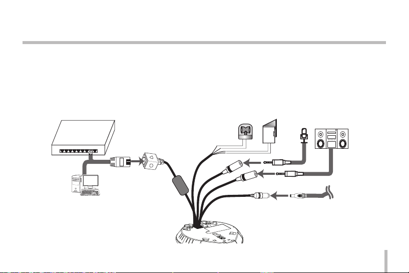
Connection Overview
PoE Device
(IEEE802.3af)
11
Connections
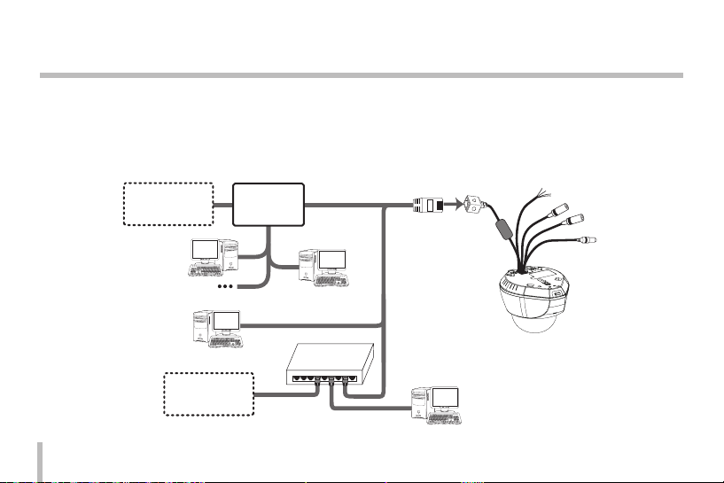
Connecting Network
You can control and monitor the system via network. With the remote control (monitoring), you can change the system configuration or monitor the image via network. After the installation, check the network settings for the remote control and
monitoring work.
Connect the IP camera to your network using a standard RJ-45 network cable as shown below.
12
Broadband
Service
Broadband
Service
Router
PoE Device
(IEEE802.3af)
Connections
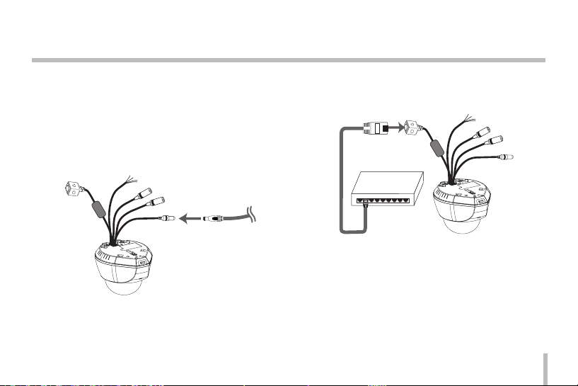
Connecting Power Source
Connect power, using one of the methods listed below:
To use the power adapter
Connect a DC 12 V power source to the power input
terminal as shown below.
(Connect to the DC 12 V UL Listed, Class 2 Power
Supply only on the unit.)
To use the PoE (Power over Ethernet) device
Connect the PoE cable to the LAN port on the unit.
You must use the “IEEE802.3af” standard PoE device.
PoE Device
PoE Device
(IEEE802.3af)
(IEEE802.3af )
Note:
If the camera doesn't work properly after connect PoE
device, please check if the PoE device is supplying enough
power.
13
Connections
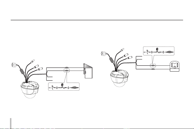
Connecting Alarm Device
Alarm terminals are used to connect the alarm (relay)
devices such as sensors, door switches, etc.
ALARM IN / ALARM IN RETURN (Sensor Input )
Connect the sensor device to the sensor input
terminal.
GREEN
BLACK
14
Sensor
Device
ALARM OUT(R) / ALARM OUT RETURN (Relay
Output)
Connect the alarm (relay) device to the relay output
terminal. Alarm signal is outputted at an event
occurrence.
RED
WHITE
Note:
The Photo MOS Relay is rated for 100 mA at 20 V DC or
100 mA at 28 V AC.
Alarm (relay)
Device
Connections
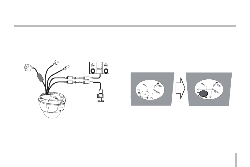
Connecting Microphone and
Speaker Device
Optionally connect an active speaker and/or external
microphone with a built-in amplifier.
Note:
Keep the microphone away from the speaker to avoid
howling.
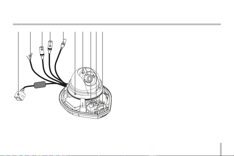
Mounting the camera
Follow the instructions below to surface mount the camera.
1. Use the installation guide template to check the
mounting location. Face the front of the label toward
the area of interest. Using the template as a guide,
make a hole through the ceiling.
15
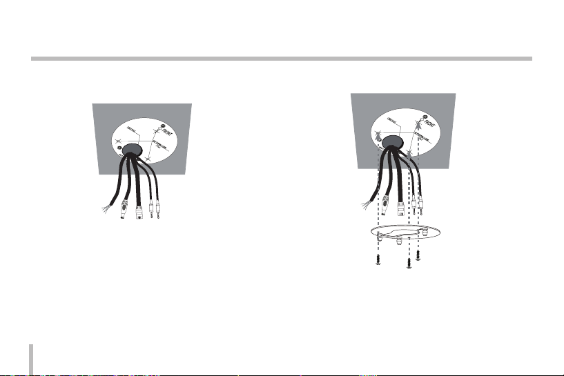
Connections
2. Pass the connection cable through the inner side of
the ceiling.
16
3. Install the camera mounting bracket to the ceiling.
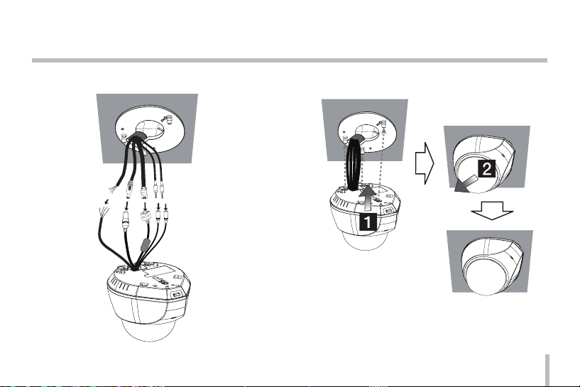
Connections
4. Connect the cables to the cable jacks of the camera
body.
5. Assemble the camera and mounting bracket. Connect
the unit by following step a and b.
17

Operation and settings
Before using the system
• Before using the LG IP device make sure the connections are correct and verify whether proper power
supply is used.
• Check the connections of the LG IP device for the correct conditions.
• Check that the LG IP device is(are) connected to the
network and that power is supplied.
• Once the connections are made you need to install the
LG client program to the PC from which you want to
access the device. The LG Smart Web Viewer program
is automatically installed when you connect the LG IP
device.
The LG Smart Station and the LG Smart Web Viewer
program are the network program of the LG Video
Server and the LG IP cameras.
• JRE (Java Runtime Environment) is a pre requisite for
LG Smart Web Viewer program. If this is missing in the
PC please install the same manually from "http://java.
sun.com" website. (Version1.6.0.11 or later)
18
• The Layouts and the Live view pages may differ with
different OS (Operating Systems) and Web Browsers.
• Care needs to be taken not to run any other applications when the Client Program is running as it may
cause memory shortage.
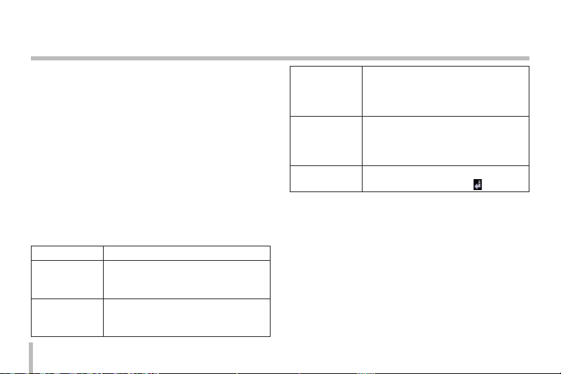
Recommended PC Requirements
The LG IP device can be used with most standard operating
systems and browsers.
Items Requirements
Operating
System
CPU
Web Browser Microsoft Internet Explorer 6.0 or 7.0
DirectX DirectX 9.0 or above
Memory 2 GB or above RAM
Graphics Card 256 MB or above Video RAM
Resolution 1280 x1024 (with 32 bit color) or higher
Windows XP Professional or above
Intel Core2 Quard Q6700 (2.66 GHz) or
above

Operation and settings
Accessing the LG IP device
You can access the LG IP device by following the below
steps.
1. Copy the IP Utility to your PC
1.1 Insert the Client Program CD.
1.2 Find and Copy IP Utility folder to your PC.
2. Discover LG IP device using the IP Utility
The IP Utility can automatically discover and display
LG IP devices on your network. The IP Utility shows the
MAC address, IP address, Model name and so on.
Note:
The computer running the IP Utility must be on the
same network segment (physical subnet) as the LG IP
device.
2.1 Run the IP Utility program.
2.2 Click the [Search] icon or select the [Search]
option in the Device search menu.
After a few seconds the found LG IP devices will
be displayed in the IP Utility window.
3. Logging in to the LG Smar t Web Viewer
The LG Smart Web Viewer can be used with most
web browsers. The recommended browser is Internet
Explorer with Windows.
3.1 Run the IP Utility and find the LG IP devices.
3.2 When the LG IP devices appear in the IP Utility
window, double-click IP address or right click on
the same IP address and select "Connect to Web
Page" to start the LG Smart Web Viewer. When
accessing the LG Smart Web Viewer, the authentication dialog appears on the screen.
3.3 Enter the user name and password. (Note that the
default administrator user name and password
are “admin”.)
3.4 Click the [OK] button and then the LG Smart Web
Viewer is displayed in your browser.
Notes:
• You can also access the LG Smart Web Viewer as
shown below.
3.1 Start your Web browser.
19
Operation and settings
3.2 Enter the IP address of the LG IP device in
the address bar of the browse.
3.3 Enter the user name and password set by the
administrator.
3.4 Click the [OK] button and then the LG Smart
Web Viewer is displayed in your browser.
• The LG Smart Web Viewer needs more time to dis-
play it according to the network conditions.
• If the login window is not displayed, check the
pop-up blocker. If you set the pop-up blocker, the
login window is not displayed. You must allow
the pop-ups.
• If you connect the LG Smart Web Viewer for
the first time, the Security Warning window is
displayed to install the LG Smart Web Viewer program. You must install the LG Smart Web Viewer
program for using the LG IP device.
• If your computer or network is protected by a
proxy or firewall, the proxy or firewall settings
can prevent the LG Smart Web Viewer program.
Change the proxy or firewall settings to activate
the LG Smart Web Viewer program.
20
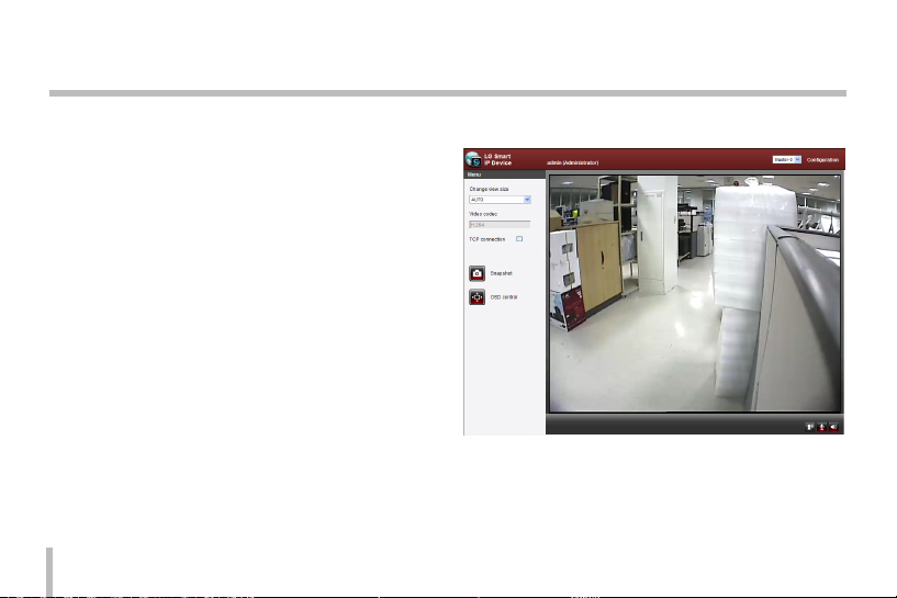
LG Smart Web Viewer Overview
Operation and settings
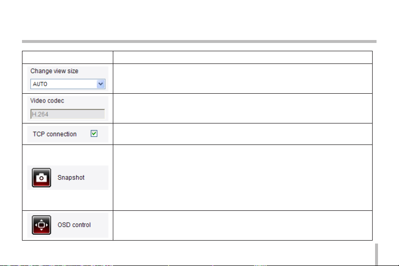
Item Description
Select the video image size from the drop-down list. (AUTO, D1 or CIF)
The initial view size is set to AUTO. The AUTO option sets the view size according to the
Server’s resolution.
Displays the current video codec of the selected video stream (Master or Slave).
Check this option as the network connection type ( TCP or UDP). If you check it, the client
connects to the server using TCP connection.
Click to save the current image in JPEG format on your computer.
1. Click the [Snapshot] button and then the Snapshot window is displayed.
2. Click the [Save] button in the Snapshot window.
3. Enter the file name (JPEG format) and select the folder to save it.
4. Click the [Save] button to confirm it.
5. Click the [Close] button in the Snapshot window to close it.
Displays the Camera OSD control window. Use these buttons to setup the Camera. This
button does not appear on the screen if the login is other than the administrator.
21
Operation and settings
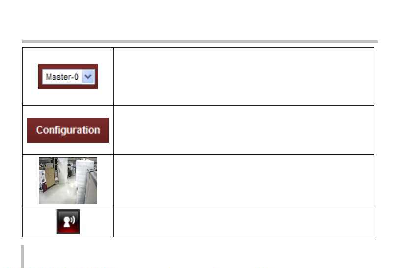
Select the video stream. From the Live view drop-down list, select the desired video
image source between [Master-0] and [Slave-0].
Note:
Master and Slave are output video streams. You can set the stream configurations independently for either Master or Slave stream. This would facilitate the user to set the live
view at his comfort.
Provides all the necessary tools for setting up the device to your requirements. The user
will need administrator level to do this.
Note:
If you want to exit the Configuration menu, select one of the video stream in the Live
view drop-down list.
Displays the current surveillance live screen.
You can monitor the camera image on the live view window of the LG Smart Web Viewer.
Click this button to connect or disconnect the audio communication between the LG IP
device and the connected PC.
(Color icon: On, Gray scale icon: Off.)
22
 Loading...