

LG LDT779 Series, LDP567 Series, LDP679 Series, LDT566 Series, LDF554 Series Owner's Manual

FRANÇAISENGLISH
OWNER'S MANUAL
DISHWASHER
Read this owner's manual thoroughly before operating the appliance
and keep it handy for reference at all times.
LDT779#** LDP679#**
LDP567#** LDT566#**
LDF554#**
MFL69261716
Rev.03_021817
www.lg.com
Copyright © 2017 LG Electronics Inc. All Rights Reserved.

11INSTALLATION
ENGLISH
INSTALLATION
Installation Parts and Tools
Parts not Provided
Electrical cable Water supply tube Fittings for tube Coupler Teon™ tape
Air gap Wire nuts for
16-gauge wiring
Hose clamp ⅞" UL approved
strain relief
Electrical tape
Tools Needed
Flat-blade
screwdriver
Phillips
screwdriver
Hole saw
min. 2½" bit
Electrical drill Gloves
Safety glasses Adjustable wrench Tape measure Utility knife Level
Tubing cutter Nipper Pliers Wire stripper ¼" Square
drive wrench
12 INSTALLATION
Installation Overview
Preparing Cabinet Opening
Preparing Electrical Wiring
Preparing Water Supply Connection
Preparing the Dishwasher
Removing Lower Cover
Sliding the Dishwasher into Cabinet
Leveling the Dishwasher
Securing the Dishwasher to Countertop
Connecting the Drain Hose
Connecting Water Supply
Connecting Power
Final Check
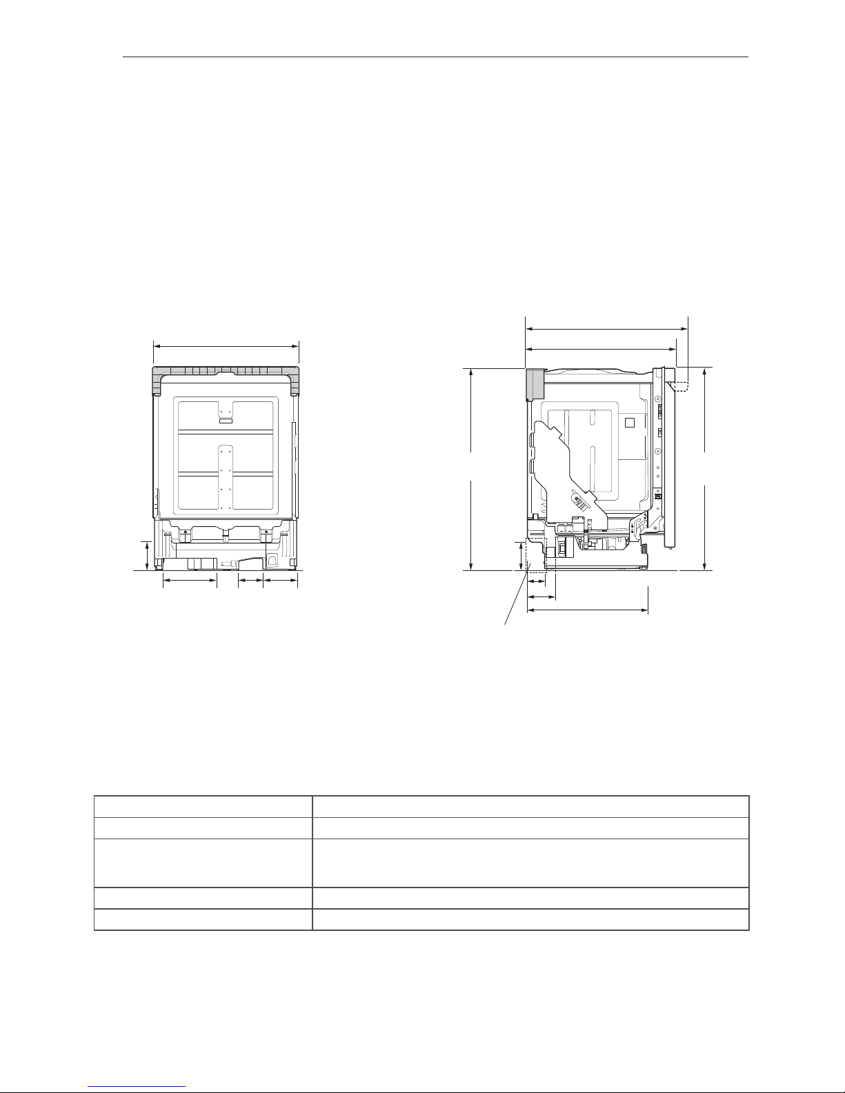
Product Dimensions
Back view Side view
33 /16"
(846 mm)
5
23 /4" (603 mm)
3
4 /2"
(115 mm)
1
33 /8"
(854 mm)
5
2 /16" (75 mm)
15
20 /16" (512 mm)
3
24 /8" (625 mm)
5
4 /4" (120 mm)
3
9 /8"
(238 mm)
3
4 /16"
(119 mm)
5
/4"
(134 mm)
11
1
4 /2"
(115 mm)
1
26 /8 - 26 /16" (676 - 681 mm)
5 13
Water supply hose, drain hose and electric cable should be passed
through this area.
NOTE
• For easiest installation, see marked areas above for water and electrical clearances in base of dishwasher.
Product Specications
The appearance and specications listed in this manual may vary due to constant product improvements.
Electrical requirement 120 V, 60 Hz AC only, minimum 15 A circuit breaker
Water pressure 20 - 80 psi (140 - 550 kPa)
Dimensions
23
3
/4"(W) X 24 5/8"(D) X 33 5/8"(H)
603 mm(W) X 625 mm(D) X 854 mm(H)
Inlet water temperature 120 °F (49 °C) minimum, 149 °F (65 °C) maximum
Net weight 72 - 89 lbs. (33 - 40 kg)
13INSTALLATION
ENGLISH
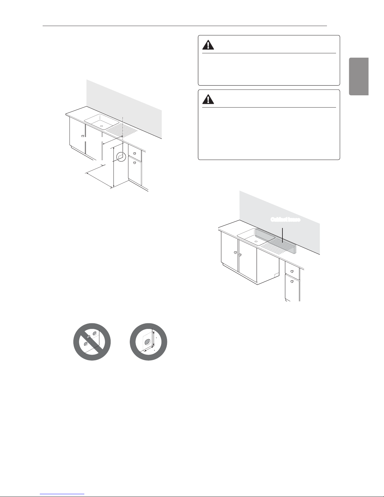
Preparing Cabinet Opening
This dishwasher is designed to t a standard
dishwasher opening. An opening may be needed
on both sides to route plumbing and electrical
connections.
24" (610 mm) min.
33 /
2" (851 mm) min.
1
24" (610 mm) min.
1
Select a location as close to the sink as possible
for easy connections to water and drain lines.
2
To ensure proper drainage, install the
dishwasher no more than 12 ft. (3.65 m) from
the sink.
3
If installing the dishwasher in a corner, leave a
minimum of 2" (50 mm) between the dishwasher
and the adjacent wall.
4
To allow for proper clearance of plumbing and
electrical, use the template included with the
literature to determine the clearance on the side
of the cabinet where the cabinet meets the back
wall. Using a 2
1
/2" diameter hole saw, drill a hole
in the target area as shown on the template.
9
4
WARNING
• Don't use existing holes unless they are in the
target area. Otherwise, the water supply and
drain hose may be damaged by being crushed
or kinked.
CAUTION
• Failure to properly locate the hole for the water
and drain lines may prevent the dishwasher from
installing ush with the cabinets and could result
in kinked or damaged lines. Installation damage
is not covered by the warranty, and leaks caused
by improper installation may result in property
damage.
For ush installations only, you may remove the
cabinet brace inside the cabinet.
Cabinet brace
 Loading...