

Page 1

P/No. : MFL37554802
Page 2

DISHWASHER
SERVICE MANUAL
BEFORE SERVICING THE UNIT, PLEASE READ THIS MANUAL CAREFULLY
FOR SAFETY AND CORRECT SERVICES.
NOTE
MODEL : LDF9810(ST,WW,BB), LDF9810 (ST,WW,BB) / 01
Page 3

1. CAUTION......................................................................................................................... 3
2. SPECIFICATION.............................................................................................................. 4
3. WIRING DIAGRAM........................................................................................................ 5
4. FEATURES & TECHNICAL EXPLANATION ................................................................... 6
5. PARTS NAME ................................................................................................................ 11
6. PROGRAM CHART ..................................................................................................... 12
7. HOW TO DISASSEMBLE ............................................................................................ 13
8. TROUBLE SHOOTING METHODS.............................................................................. 22
A. TROUBLE SHOOTING ACCORDING TO DISPLAYED ERROR MESSAGE ......... 22
B. STEAM GENERATOR ERROR MESSAGE............................................................. 24
C. TROUBLE DIAGNOSES AND REPAIR BY SYMPTOM........................................... 25
9. INSTALLATION INSTRUCTION ................................................................................... 29
10. EXPLODED VIEW ...................................................................................................... 36
11. REPLACEMENT PART LIST ....................................................................................... 42
CONTENTS
- 2 -
Page 4

- 3 -
DISCONNECT POWER CORD BEFORE SERVICING
RECONNECT ALL GROUNDING DEVICES
IMPORTANT SAFETY NOTICE !
This service information is intended for individuals
possessing adequate backgrounds of electrical,
electronic and mechanical experience.
Any attempt to repair this appliance may result in
personal injury and property damage.
The manufacturer or seller can not be responsible
for the interpretation of this information, nor can it
assume any liability in connection with its use.
CAUTION
Page 5
- 4 -
Rated Voltage / Frequency AC 120V/60Hz
Installation Built-In
Place Settings 14
Product Dimension(in) 23 7/8
〃x 25〃x 33 7/8〃
Product Weight(lbs) 128lbs
Door Color White, Black, Stainless
Tub Material Stainless Steel
Control Electronic
Rated Power(Watt) 1,350
Heater Power(Watt) 1,200
Programs 6 Cycle
Upper Rack Position Adjustable
Lower Rack 50% Fold down
Cutlery Rack Yes
Water Consumption
10-26 (Normal)
Power Consumption(kWh/year) 285~310
Operating Time (min) 101-135 (Normal)
Fan Dry System Yes
Steam Generator Yes
Delay Start Function Yes
Auto-Off Power Switch Yes
Process Monitor Yes
Wash Level 5
Racks Nylon Coating
Operating Water Pressure (Bar) 20-120 (140-830kPa)
ITEM
SPECIFICATION
2. SPECIFICATION
Page 6
- 5 -
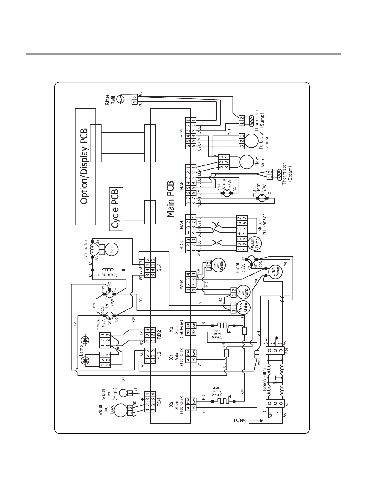
1. LDF9810 series
3. WIRING DIAGRAM
Page 7
- 6 -
4. FEATURES & TECHNICAL EXPLANATION
4-1. Product Features
If you raise the upper rack, you can load large dishes (Max. 14 in.) in the lower
rack. The tall tub provides the clearance to handle large dishes as well as
overall large capacity. LG dishwashers let you load very large items in the
upper and lower racks.
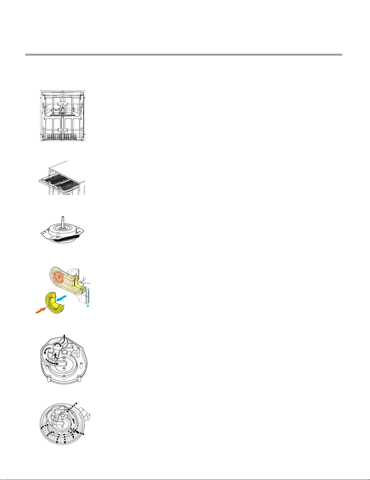
The new
Slim Direct Motor
TM
is inverter-controlled. Wash power is controlled
based on program selection. It also offers high energy efficiency to minimize
energy use.
This is one of the best performance solutions for drying dishes because it
minimizes venting humid air to the outside of the dishwasher. In addition, this
system ensures better drying results compared to the condensing drying
system while minimizing energy consumption.
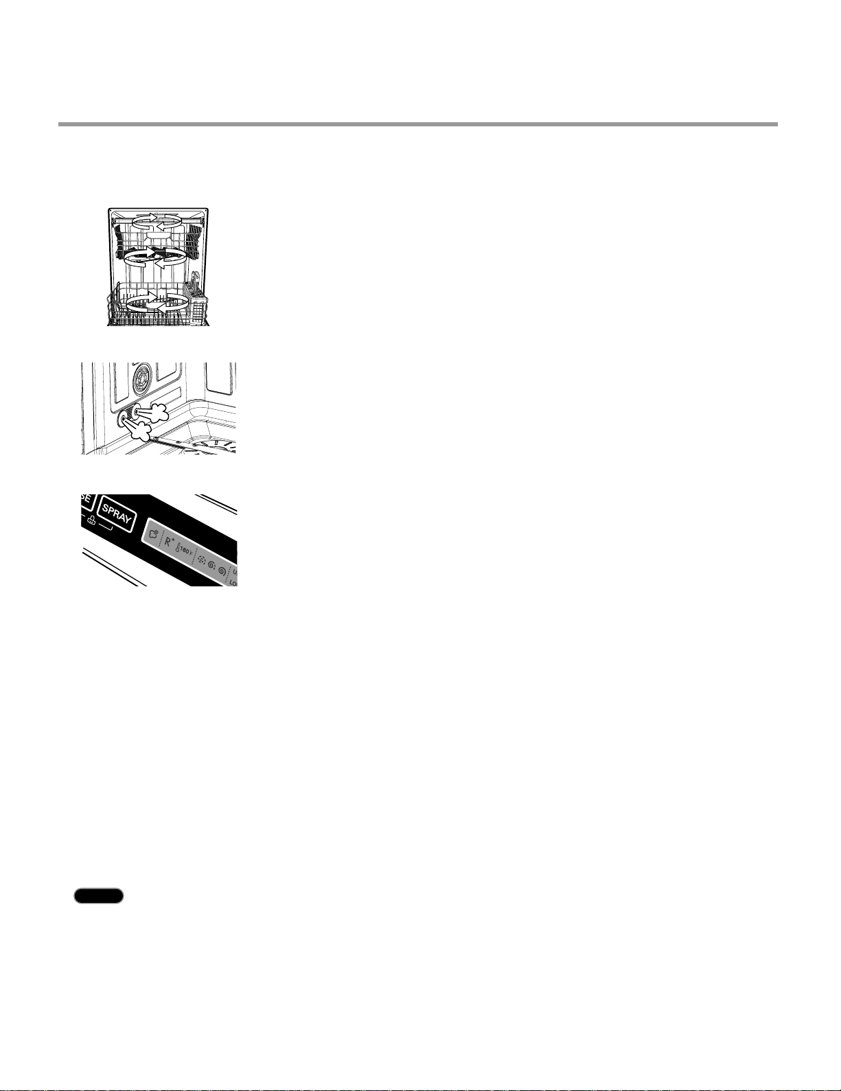
Because the water spray is alternated between the upper and lower
racks, all the power from the motor is directed to only one rack at a time which
allows superior performance and reduced consumption of water and
electricity.
For best wash results, the self-cleaning filter system continuously cleans the
water as it circulates. Your LG dishwasher has a self-cleaning filter that grinds
food into small particles before it goes down the drain.
■■
Ultra Large Capacity
■■
Slim Direct Motor
TM
■■
Hybrid Drying System
■■
Vario Spray System
■■
Self-Cleaning Filter
Third level cutlery rack makes it easy to load and unload flatware and cooking
utensils.
Trays can be adjusted or removed to make more room for regular upper rack
items.
■■
Removable Cutlery Rack
Moist
Air
Dry
Air
Mixed
Air
to
Upper
Arm
to
Lower
Arm
Soil Sensor
Fine Mesh
to Drain
Page 8
- 7 -
4-2. How To Use Dual Intensity™
Adding STEAM to the wash cycles enhances wash performance with very little
additional water or energy consumption. The SteamDelicate™ cycle can be
used for cleaning delicate item such as china or stem ware.
■■
Steam Washing and Steam Delicate™
The light touch buttons on the control panel make selections easy and
convenient, while the blue LCD display clearly displays the selected cycle and
options.
■■
Light Touch Buttons and Blue LCD
The spray intensity of the upper and lower racks is programmable by the
consumer. You can select wash power based on soil level. For example, by
selecting Soft Spray for the upper rack and Strong Spray for the lower rack,
you can wash delicate items like stemware on the upper rack
while washing pots and pans on the lower rack.
■■
Dual Intensity
TM
Wash Cycle
4-3. Auto-Off
When the power is turned on, if you don’t select program or if you don’t close the door after selecting a
program, your dishwasher will automatically turn off in 10 minutes.
1. Select the desired wash cycle.
2. Press and hold the
SPRAY key for 3 seconds. Both the UPPER and LOWER indicators will be
illuminated indicating that both racks will be washed. The UPPER indicator will be blinking to show this
is the rack selected for adjustment of the spray intensity.
3. Press the SPRAY key repeatedly to set the desired spray intensity for the UPPER rack
(Strong/Medium/Soft).
4. Press the HALF LOAD key to switch to the LOWER rack. The LOWER rack indicator will now be blinking.
5. Press the SPRAY key repeatedly to set the desired spray intensity for the LOWER rack
(Strong/Medium/Soft).
6. Select other options as desired.
7. Close the door to start the dishwasher.
8. To cancel the Dual Intensity™ wash option, simply press one of the cycle keys. The default settings for
that cycle will be displayed.
NOTE Once the cycle has started, cycles and options cannot be changed.
Page 9
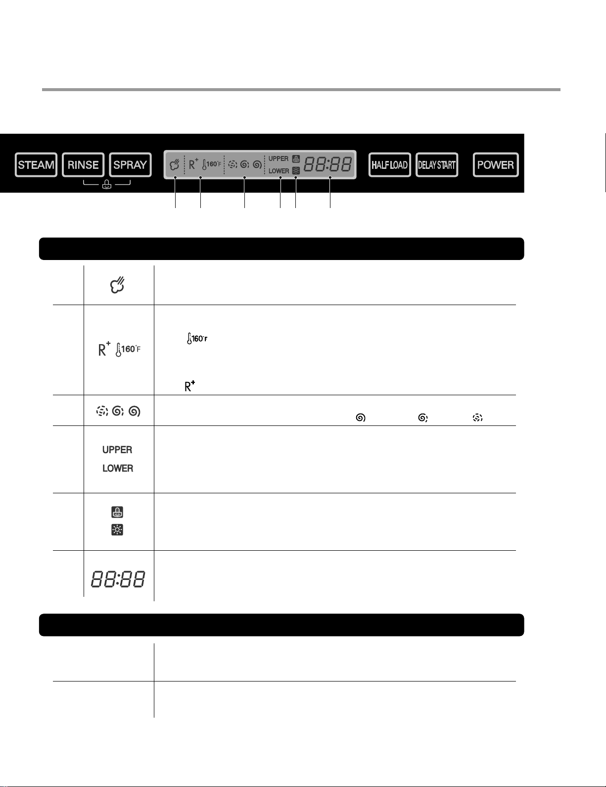
- 8 -
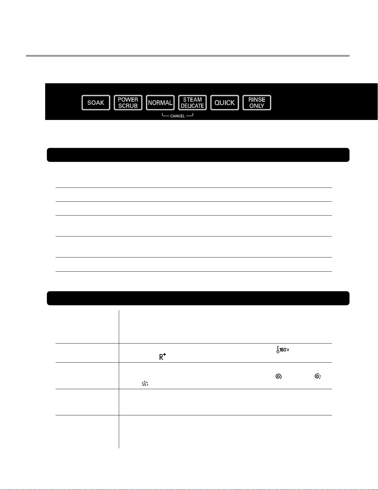
4-4. Display Panel
This cycle is for very heavily soiled loads including pots, pans,
and casserole dishes, which may have cooked on food.
Press the STEAM button to add steam to the selected cycle for added cleaning
power.
NOTE : Steam can only be added to the following cycles:
SOAK, POWER SCRUB, NORMAL.
Repeated pressing of the RINSE key will select Sanitary( ),
Extra Rinse( ) or both.
Select the spray intensity that matches your cleaning needs.
Repeated pressing of the SPRAY key will select Strong ( ), Medium ( ) or
Soft ( ).
For smaller loads, use this option to wash only the upper or lower rack to save
energy.
Press
HALF LOAD repeatedly to select either the upper or lower rack.
Use this option to start the dishwasher at a later time.
Press
DELAY START repeatedly to delay the beginning of the selected cycle.
Each press of the button will increase the delay time by one hour. Maximum
delay is 24 hours.
This cycle is for normally soiled, every day loads.
This cycle is for normally soiled, every day loads.
This cycle is for washing delicate items like china or stemware.
This cycle is for quick wash of lightly soiled, recently used dishes, and
cutlery.
This cycle is just for rinsing dishes quickly. No detergent is used.
SOAK
STEAM
RINSE
SPRAY
HALF LOAD
DELAY START
POWER SCRUB
NORMAL
STEAM DELICATE
QUICK
RINSE ONLY
CYCLE
OPTION
Page 10
- 9 -
To cancel a running cycle, open the door, then press and hold the STEAM
DELICATE and NORMAL buttons together for 3 seconds.
The drain pump will be activated and the cycle will be canceled.
To lock/unlock the buttons, press SPRAY and RINSE simultaneously for 3 seconds.
When CHILD LOCK is set, the CHILD LOCK indicator will appear and all buttons are
disabled.
CANCEL
CHILD LOCK
CANCEL & CHILD LOCK
STEAM OPTION INDICATOR
Indicates that the STEAM option has been selected. The symbol will blink while
steam is being injected into the dishwasher.
RINSE INDICATOR
It shows configuration of rinse option.
The ( ) symbol indicates that sanitary rinse has been selected.
The symbol blinks during the cycle if the sanitary temperature has been achieved.
Once the cycle has ended, the symbol will be steady if the sanitary temperature has
been achieved. (See NOTE below.)
The ( ) symbol indicates that an extra rinse has been added to the selected cycle.
SPRAY INDICATOR
Indicates the selected spray intensity: Strong ( ), Medium ( ) or Soft ( ).
HALF LOAD INDICATOR
Each press of the HALF LOAD key cycles between upper rack only and lower rack
only.
When DUAL INTENSITY is selected, both lights will be and one will be blinking. The
spray intensity for the blinking rack can be adjusted independently.
CHILD LOCK
This symbol will be visible when Child Lock is activated.
RINSE AID
The symbol will be activated when the rinse aid needs to be refilled
TIME REMAINING
Indicates normal run time for the cycle selected.
During the cycle, the estimated time remaining for the selected cycle will be
displayed
INDICATOR
Page 11
- 10 -
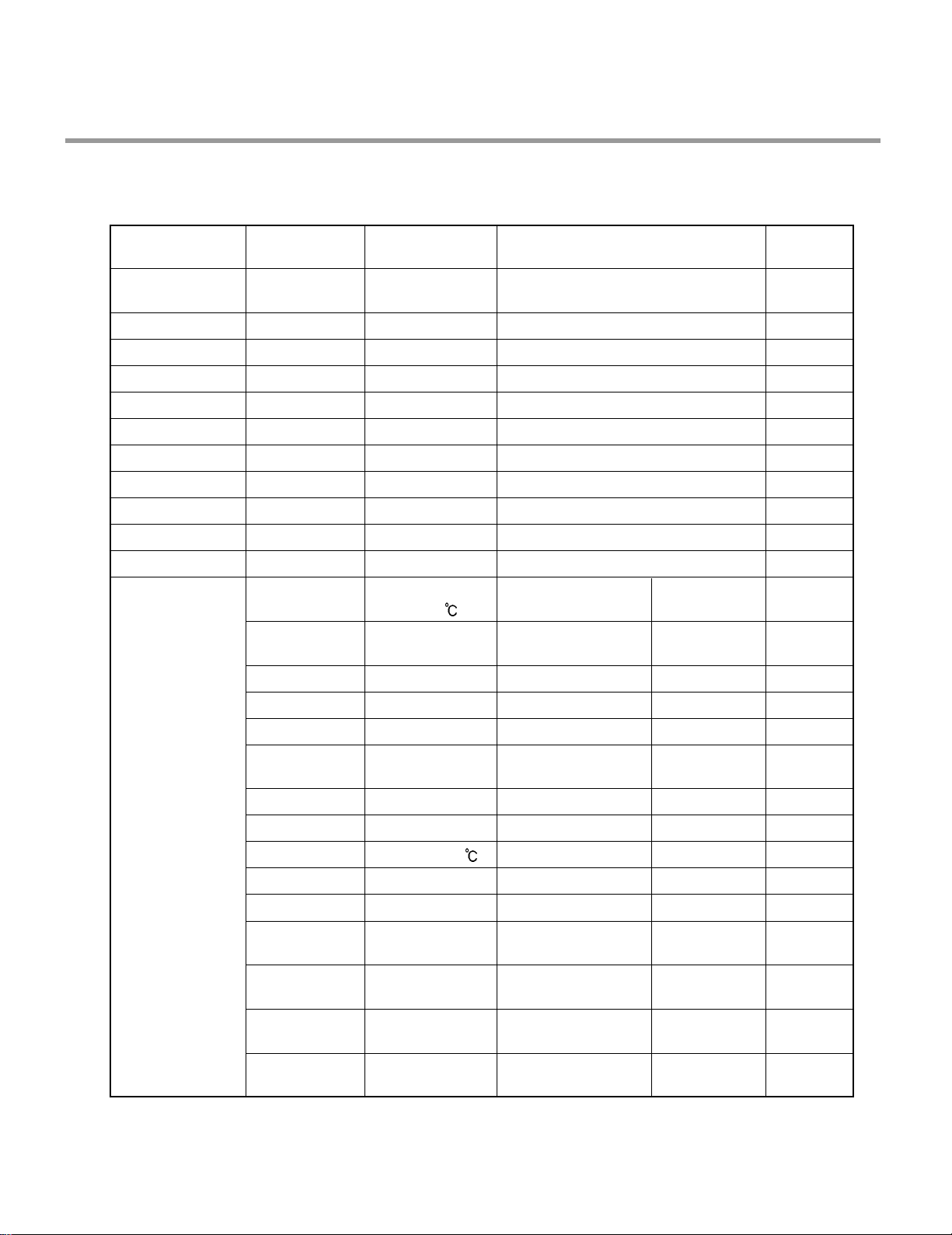
4-5. TEST MODE
CHECK PROGRAM
BUTTON
The number of
pushing button
Top
Display
Load and Checking points
Door open/
closed
Rinse + Spray
+ Power
Soak
Power Scrub
Normal
Steam Delicate
Quick
Rinse Only
Steam
Rinse
Spray
Half Load
Delay start
Normal water level : 270 ~ 275
Pure water : more than 130
H: High water level / L: Low water level
1 TIME
1 TIME
1 TIME
1 TIME
1 TIME
1 TIME
1 TIME
1 TIME
1 TIME
1 TIME
1 TIME
1 TIME
2 TIME
3 TIME
4 TIME
5 TIME
6 TIME
7 TIME
8 TIME
9 TIME
10 TIME
11 TIME
12 TIME
13 TIME
14 TIME
15 TIME
Steam generator
Temp(
)
0n:H1
0n:33
Frequency
0n:35
0n:36
0n:37
0n:38
Sump Temp(
)
Soil level
0n:3b / Motor RPM
Steam generator
Water level
0n:3d
0n:3E
0n:3F
(RPM, Frequency)
0n:3H/0U:00
00:00
11:11
22:22
33:33
44:44
55:55
66:66
77:77
88:88
99:99
Steam generator
Thermistor
Steam generator
Heater (for 1.2 sec)
Drain Pump
Inlet Valve
Dispenser
Sump Heater
(for 10 sec)
Fan Motor
Sump Thermistor
Soil sensor
Wash Pump
H170/L170
Lower Nozzle
(Vario)
Upper Nozzle
(Vario)
W/Pump+Vario+
Heater (for 1min)
All LEDs
All LEDs
All LEDs
All LEDs
All LEDs
All LEDs
All LEDs
All LEDs
All LEDs
All LEDs
All LEDs
All LEDs
All LEDs
All LEDs
All LEDs
All LEDs are lighting Both
All LEDs are lighting
All LEDs are lighting
All LEDs are lighting
All LEDs are lighting
All LEDs are lighting
All LEDs are lighting
All LEDs are lighting
All LEDs are lighting
All LEDs are lighting
All LEDs are lighting
Both
Both
Both
Both
Both
Both
Both
Both
Both
Both
Both
Closed
Both
Closed
Closed
Closed
Closed
Closed
Both
Both
Closed
Both
Closed
Closed
Closed
※ Steam Demo mode : Steam + Power
Page 12

- 11 -
5. PARTS NAME
The appearance and specifications may be varied without notice according to localities.
INSTALL BRACKET WOOD SCREW LEVELING KIT
LDF 9810 Series
Control Panel
Door Handle
Front Cover
Lower Cover
Leveling Foot
Side Cabinet
Base
Top Spray Arm
Upper Spray Arm
Removable Tines
Steam Nozzle
Lower Spray Arm
Detergent & Rinse Aid Dispenser
Vapor Vent Cover
Tub Lamp (IllumiTubTM)
Cutlery Rack
Upper Rack
Cutlery Basket
Lower Rack
Blue LCD Display
Power Button
Page 13
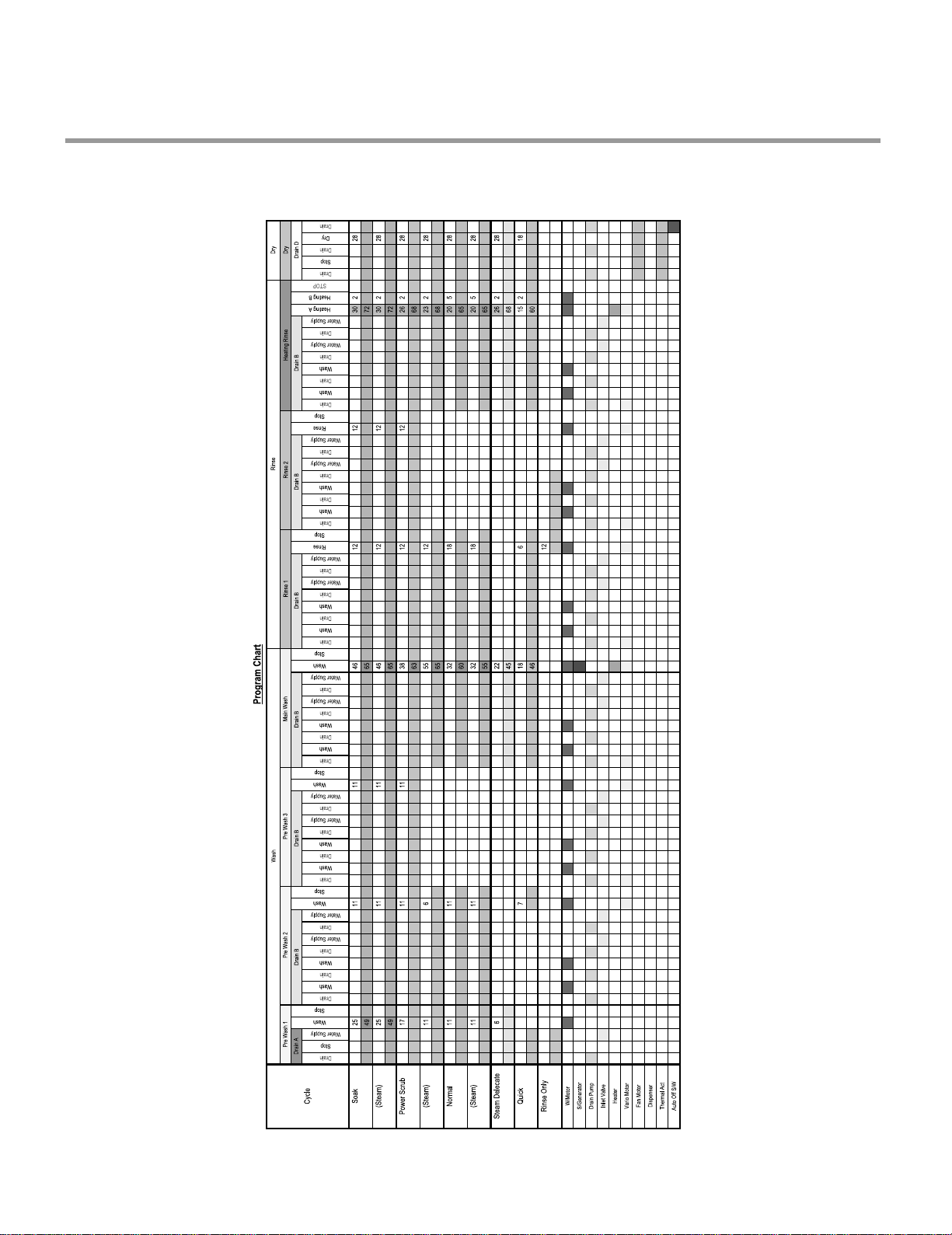
- 12 -
6. PROGRAM CHART(SCHEMATIC DIAGRAM)
LDF 9810 Series
Page 14
- 13 -
BEFORE DISASSEMBLING THE DISHWASHER ;
1) Remove the cord from electric outlet to avoid electric shock.
2) Close the Water Tap (faucet).
3) Remove all dishes and items in the dishwasher.
4) Remove the Lower Rack and the Upper Rack.
5) Remove the inlet hose and drain hose connetion to avoid the hose damages.
6) Prepare some towels to avoid floor wet by the water left in the dishwasher.
7. HOW TO DISASSEMBLE
7-1. FULL DISASSEMBLE
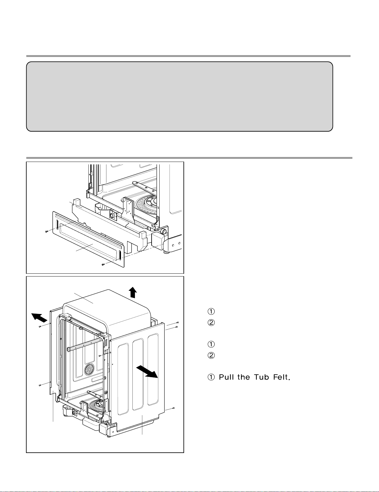
1. Lower Cover and Lower Felt
1) Remove the front 2 screws.
2) Pull the Felt.
3) Remove the Inlet Hose and Power Supply
Cable.
2. Cabinet and Tub Felt
1) Cabinet-R
Remove front 2 screws.
Remove rear 3 screws.
2)
Cabinet-L
Remove front 2 screws.
Remove rear 3 screws.
3)
Tub Felt
Lower Felt
Lower Cover
Cabinet-L
Tub Felt
Cabinet-R
Page 15
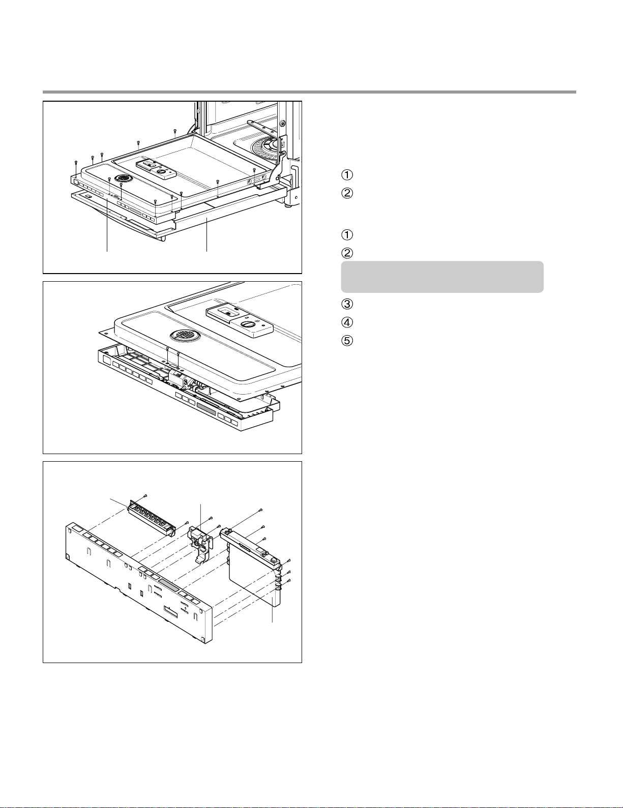
Control Panel Front Cover
C
3. Door Assembly
(LDF 6810/7811/7810/8812 Series)
1) Front Cover
Open the door.
Remove 12 screws(stainless).
2) Control Panel Assembly
Remove 2 screws(Stainless).
Remove the wire connections.
Be sure the wiring should not be
changed in reassembling
Remove the Latch assembly.
Remove the Front Display.
Remove 8 screws for Controller.
- 14 -
ontroller
Latch Assembly
Controller
Page 16
- 15 -
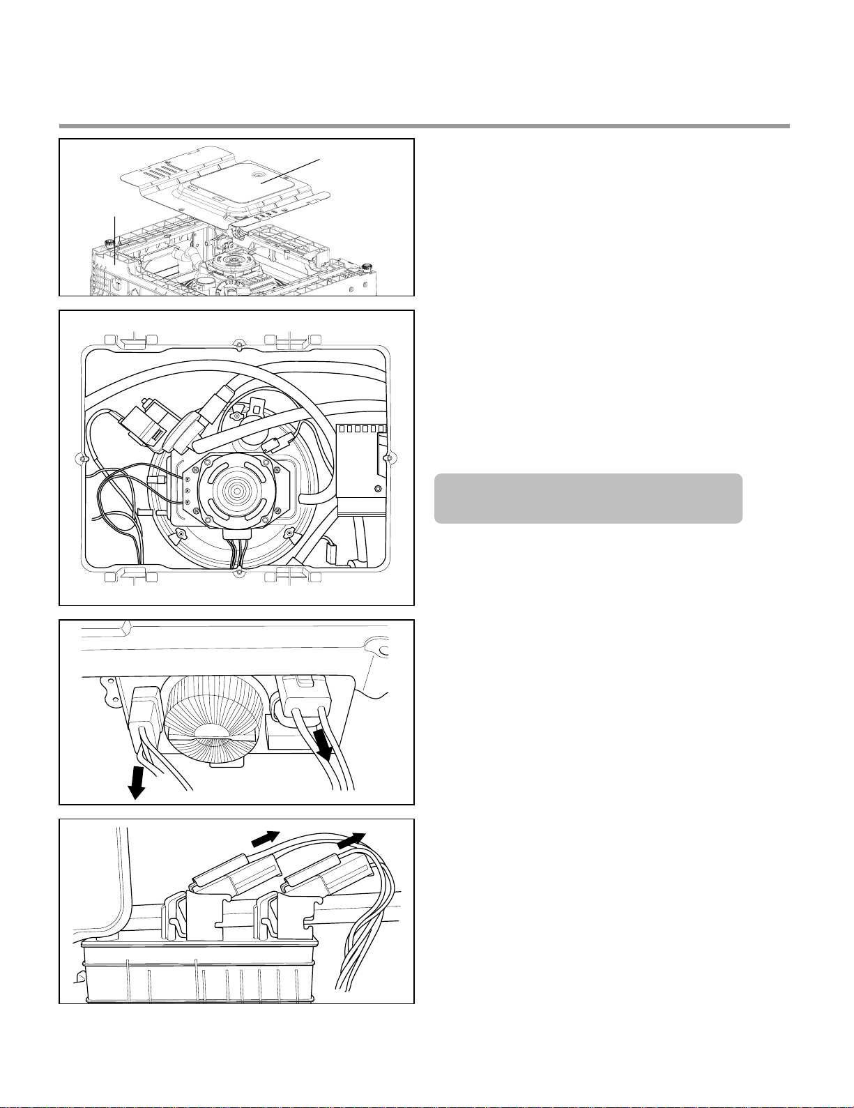
H
H
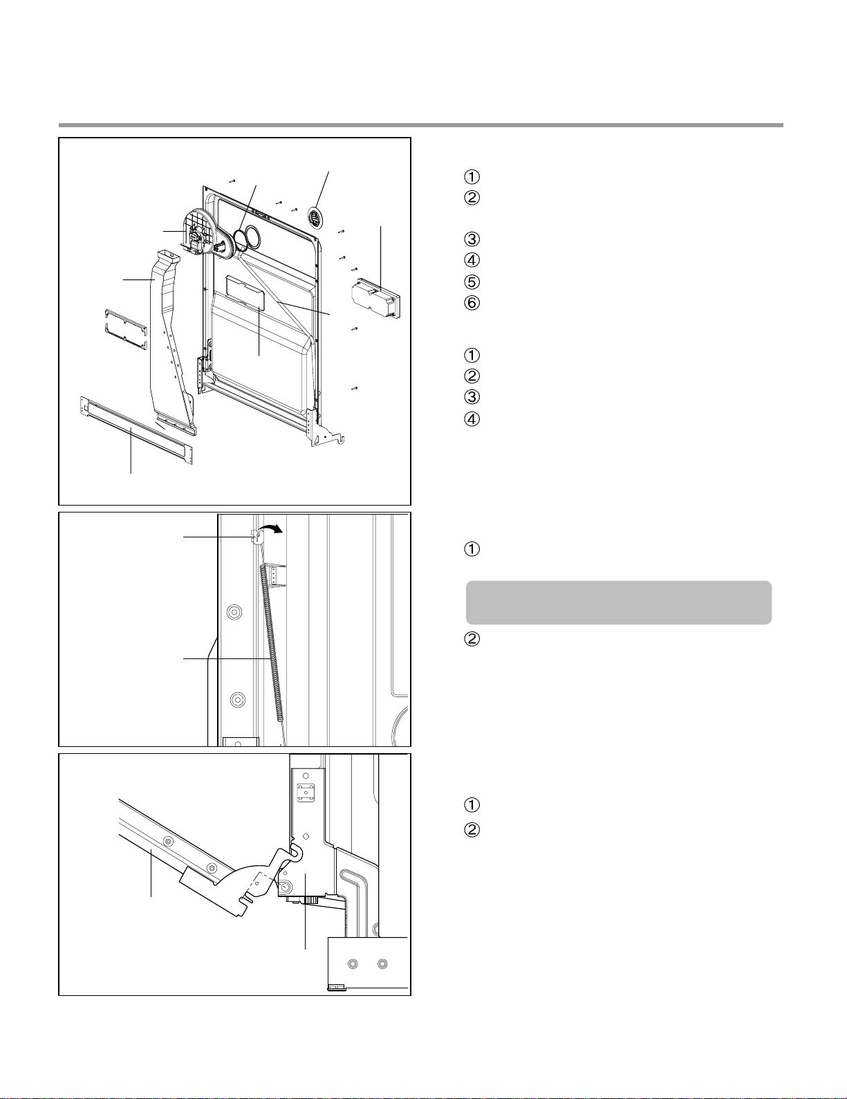
3) Fan Assembly
Open the Door.
Remove 4 screws and a earth screw for
Door Bracket.
Remove the wire connector.
Ramove the Air Duct.
Ramove Hose with Clamp.(Some Moels)
Turn the Inner Cover counterclockwise.
4) Detergent Dispenser
Close the door
Remove the wire connections.
Remove 6 screws with brackets.
Push the Detergent slowly pulling up the
the Flange by Standard Screwdriver.
5) Door Spring (Right & Left)
Push the Spring upwards and take it off
from the Hinge Bracket.
Be careful not to be injured by the
sharpedge of Tub.
Take off the Hinge Link from the Hinge.
6) Door Liner
Open the door.
Pull the Door Liner and take it off from
the Hinge Supporter.
Door Liner Assembly
Hinge Supporter
Fan Assembly
Air Vent
Door Bracket
Frange
Hose
Gasket
Inner Cover
Detergent
Dispenser
inge Bracket
inge Spring
Page 17
- 16 -
Lead Wire Holer Hook
Lead Wire Holer
Lower Frame
D
H
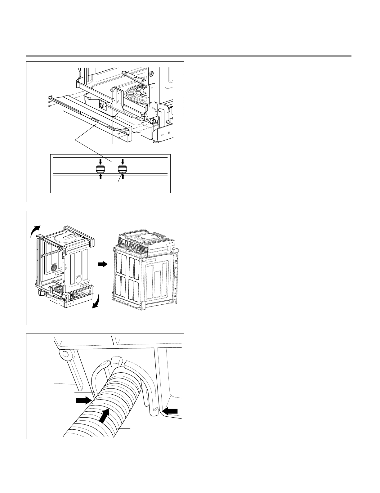
4. Lower Frame
1) Press the holder hook as shown in figure.
2) Remove 4 screws.
6. Drain Hose Holder
1) Press the holder hook as shown in figure.
2) Pull the Drain Hose and remove the Drain
Hose Holder.
5. Put the Dishwasher upside down.
rain Hose
older
Drain Hose
Page 18
- 17 -
7. Base Cover
1) Remove 2 screws.
2) Pull the Base Cover out.
8. Harness & Hose Assembly
1) Remove the wiring connections.
2) Remove the Hose connections from
Sump Assembly.
You can see the information of Wiring
Diagram at the back of Lower Cover.
Cabinet Base
Base Cover
Page 19

- 18 -
9. Cabinet Base
1) Remove 8 screws.
2) Lift it upward.
Cabinet Base
Float Assembly
WaterLevel
Sensor (High)
Thermistor
Heater
Water Level
Sensor (Low)
10. Float Assembly
1) Press the Float hook.
2) Pull the Float Assembly
11. Steam Generator
1) Disconnect the 3 hoses assembly.
2) You can disassemble the Steam generator
by removing the 2 screws.
Steam
Generator
CAUTION
Be cautious in case of the generator is hot
temperature.
Page 20

- 19 -
12. Inlet Valve
1) You can disassemble the lnlet Valve by
removing the 2 screws.
13. Air Braker Assembly
1) Disconnect the 3 hoses assembly.
2) Turn the Air Braker Nut counterclockwise.
Be careful the o-ring should not be lost.
Cabinet Base
Inlet Valve
Air Braker
Nut
Gasket
Air Braker
Assembly
Page 21

- 20 -
Sump Holder
Hook
Sump
Assembly
1) Heater & Drain Motor
Pull the Heater out of the Sump after
releasing the nut.
Remove 3 screws.
2) Vario Motor
Remove 2 screws for Vario Motor.
Pull the Vario Motor and Micro S/W.
3) Soil Sensor
Pull the Soil Sensor.
14. Sump Assembly
Remove 2 screws.
Remove the Sump Holder and push the
Sump Assembly down with pulling aside
Hook.
Be careful not to drop the Sump
Assembly to the bottom.
Drain Pump
Heater
Vario Motor
Micro
S/W
Soil
Sensor
Page 22

- 21 -
15. Holder Supporter, Tub Packing
and Hinge Supporter Assembly.
When you reassemble the Sump Assembly, be
careful not to kink, tear and take off the seals.
You must take off Stopper Roller(F117) by –
screwdriver to change the Rail Assembly.
(Stopper Roller could be broken while you are
taking off. So you should be careful not to be
hurt and have extra stopper rollers ready at
servicing at all times)
Cutlery Rack Rail
Upper Rack Rail
1. Pull the upper rack out until it stops.
2. Squeeze the tab of the stopper and pull out.
Be careful the upper rack does not fall off
the rail while pulling out the stopper.
3. Pull the upper rack out of the slides.
Rotate the screwdriver, after slide it into the
gap between Stopper Roller and Rail Roller.
Squeeze Tab
Page 23

- 22 -
A. TROUBLE SHOOTING ACCORDING TO DISPLAYED ERROR MESSAGE
ERROR MESSAGE
POSSIBLE CAUSE
REMEDY
FOR ERROR OCCURRENCE
The Water Supply Tap is closed.
The Water Supply is shut off.
The Inlet Hose is kinked.
The Water Pressure is very low.
(below 10 psi)
Inlet Valve is OK?
The filter of Inlet Valve is clogged
by impure water.
The Hall sensor is OK?
The Impeller of Air Guide is bound.
The Drain Hose kinked or blocked.
Wiring connection is OK?
The drain outlet of sump is
blocked.
The Drain Pump/Motor or circuit is
troubled.
Water leakage in Hose connections.
Water is leaked by damages.
The Motor Water Seal leakage of
Sump assembly.
The height of Drain Hose connection
(sink-Drain Hose) is not over 20″
.
Impeller of the Washing Pump is
worn away.
Remove the cause of kink or block.
Check the wiring connection.
Measure the electric resistance of
Drain Motor. (20-40
)
Replace the Drain Motor or repair
the Circuit.
Replace the connections of Hose.
Check the point of damages and
repair or replace the related parts.
Read the Installation Instructions
(page 9) and fix it to the
recommended Height.
Replace the Impeller of the
Washing Pump.
Take action on Water Supply
device.
Measure the electric resistance of
Inlet Valve. (950-1300
)
Clean the filter of Inlet Valve.
Check the frequency of Inlet Water
by the Test Mode.
Replace the Air Braker.
Not reached to the normal water level in spite
of 10 min. water supply
INLET ERROR
displayed
Condition
Not fully drained out in
spite of 5 min. drain
operation
The excessive RPM of
Washing Motor
happened during Wash
cycle due to water
leakage.
DRAIN ERROR
displayed
Condition
LEAKAGE ERROR
displayed
Condition
8.TROUBLE SHOOTING METHODS
Page 24

- 23 -
ERROR MESSAGE
POSSIBLE CAUSE
REMEDY
FOR ERROR OCCURRENCE
The Inlet Valve is troubled.
The Controller is troubled.
The Inlet Water Temperature is
very high. (over 194
)
Wiring connection is OK?
The Thermistor is OK?
Wiring connection is OK?
The Impeller of Washing Pump is
locked.
The rotor of Washing Motor is
locked.
The Blade is locked.
Check the temperature. (Test Mode)
If the temperature is displayed,
adjust the Inlet Water
Temperature to 120 .
If the temperature is not
displayed,
check the wiring connection.
check the electric resistance
of Thermistor.
(11~14k
at 77 )
Replace the PCB.
Replace the Inlet Valve.
Repair or replace the Controller.
Excessive water is supplied than normal water
level.(Automatically drain
Pump operated.)
EXCESS ERROR
displayed
Condition
The resistance of thermistor not normally out put.
THERMAL ERROR
displayed
Condition
Check the wiring connection.
Replace the cause of restriction.
Replace the Washing Motor.
Replace the PCB.
The Motor is working
abnormally.
MOTOR ERROR
displayed
Condition
Page 25

- 24 -
B. STEAM GENERATOR ERROR MESSAGE
The normal condition
The generator heater temperature
is high. (over 239
℉ )
The water leveling sensor is working
abnormally.
Not reached to the normal water
level.
The generator heater temperature
is low. (lower than 158
℉ )
The normal condition
Check the water level sensor and
thermistor check.
Check the wiring connection and
water level sensor.
Check the inlet valve and sensor
connection.
Check the heater and thermistor.
00 : E0
00 : E1
00 : E2
00 : E3
00 : E4
00 : E5
ERROR MESSAGE CONDITION REMEDY
Steam Generator Error mode is not displayed in normal condition and it can be confirmed
by following additional operation.
To confirm steam generator error, press the DELAY START and RINSE ONLY buttons
simultaneously.
When Steam Generator is out of order, dishwasher operates the selected cycle without
steam.
Page 26

- 25 -
No Power on when the power button pressed.
The Power connection
is correctly connected.
The Fuse or
Circuit Breaker
of house is O.K?
The Power Switch or
the Circuit is O.K?
• Re-connect the Powr connection.
• Check the electricity is failed or not.
• Replace the Fuse or Circuit Breaker of house.
• Check the Power Switch or the circuit and repair it.
Check the Controller.(Power Circuit)
C. TROUBLE DIAGNOSES AND REPAIR BY SYMPTOM
NO
NO
YES
YES
YES
NO
Page 27

- 26 -
The Wash Pump/Motor does not run.
The Door is tightly
closed?
The Wiring connections
is OK?
The Blade is not locked
by a small and sharp
object?
• close the Door tightly.
• Check the Door Switch in Latch Handle.
• Re-connect the wiring connections related to the
Washing Motor.
• Remove the cause of lock or replace the Blade.
Replace the Wahing Pump/Motor
NO
NO
NO
YES
YES
YES
Page 28

- 27 -
Washing Results are not Satisfactory
After washing, are there still
White deposits or streaks on
the dishes?
NO
After washing, are there still
food soils on the dishes?
YES
Check that : - the amount of detergent Correctly used or not
- Filters clogged or not.
- the holes of spray arms blocked or not.
- Utensils are correctly arranged or not.
- Utensils are overloaded or not.
- the spray arm rotating is obstructed or not.
- the program is correctly selected or not.
Reduce the amount of Rinse-Aid
(for Streak)
YES
Dry Results are not satisfactory
Increase the amount of Rinse-Aid.(Set the number higher)
Select the Program that the Rinse temperature is higher.
Page 29

- 28 -
Power Button not automatically off after operation.
Check the button is blocked by foreign materials.
Check the Power Switch.(Replace it, if necessary.)
Check the Controller.(Replace it, if necessary.)
Page 30

- 29 -
9. INSTALLATION INSTRUCTION
Step 1: PREPARE CUPBOARD OPENING
1. This dishwasher is designed to fit a standard dishwasher opening as shown below.
2. Select a location as close to sink as possible for easy connections to water and drain lines.
3. The dishwasher should not be installed more than 10 ft. (3m) from the sink for proper
drainage.
4. If dishwasher is to be installed in a corner, a minimum of 2 in. (50mm) is required between
the dishwasher and an adjacent a wall.
■ Ensure the floor under the dishwasher is at the same level as the rest of the room to
allow for any service requirements.
If dishwasher will sit directly on
subflooring, subfloor should be
sealed with a waterproof paint or
sealer to prevent damage from
steam.
Drill a 1-1/2″″(38mm) dia hole or cut
out for drain hose, inlet hose and
electrical cables on either side.
approx. 4″″(100mm, W) X 4″″(100mm, H)
These openings must be within 4
″″
(100mm) from the floor and 1-5/8″
(40mm) from the back wall. If there is
a floor in the cabinet under the sink,
it will also be necessary to drill or cut
through the floor to connect the
water and drain under the sink.
1. This dishwasher is designed to fit a standard dishwasher opening as shown below.
2. Select a location as close to sink as possible for easy connections to water and drain lines.
3. The dishwasher should not be installed more than 10 ft. (3m) from the sink for proper
drainage.
4. If dishwasher is to be installed in a corner, a minimum of 2 in. (50mm) is required between
the dishwasher and an adjacent a wall.
Page 31

- 30 -
For personal safety, remove house fuse or open circuit breaker before installation.
Do not use an extension cord or adapter plug with this dishwasher.
Electrical and grounding connections must comply with the national electrical
code/provincial and municipal code and/or other local codes.
Figure A
Step 2: PREPARE THE ELECTRICAL WIRING
1. This appliance must be operated with correct voltage as shown in this manual and on the
rating plate, and connected to an individual, properly grounded branch circuit, protected
by time delay fuse. Wiring must be 3 wires including ground.
2. The wiring or cord should be in an accessible location adjacent to, and not behind the
dishwasher and within 4 ft. (1.2m) of the dishwasher side.
3. The wiring or cord must be grounded properly, if in doubt, have it checked by a qualified
electrician. No other appliance shall be connected to the same outlet by a double adapter
or similar plug.
4. The wiring or cord must be oriented as shown in Figure A below.
5. Check the dishwasher for any damage before trying to install it.
6. Make sure water line and Electrical line are oriented in the bottom channels as shown in
the figure below.
If you find any damage to the dishwasher, Please contact your dealer or builder
immediately.
WWAARRNNIINNGG
Page 32

- 31 -
Step 3: PREPARE THE WATER SUPPLY CONNECTION
1. This dishwasher may be connected to either hot or cold water. If the water can not be
maintained below 149(65), the dishwasher must be connected to cold water.
2. When connecting the dishwasher water line, sealing tape or compound should be used to
avoid leaks.
3. When connecting the dishwasher water line, the house supply should be shut off.
4. The Water Supply Tube must be oriented as shown in Figure A on page 6.
Step 4: PREPARE DISHWASHER FOR INSTALLATION
1. Adjust the legs to the required height to fit properly under the countertop as shown below.
2. Check the level of dishwasher by using level.
Page 33

- 32 -
1. Remove the Lower Cover and orient dishwasher as shown below.
2. Before sliding the dishwasher into the cupboard opening, make all necessary height
adjustments using the legs.
3. Slide the dishwasher into the cabinet opening carefully. Make sure that the drain hose
inside the cabinet is not kinked.
4. Follow the instruction as in Figure B.
Step 5: INSTALL THE DISHWASHER IN CUPBOARD
Page 34

- 33 -
Step 6: DRAIN LINE CONNECTION
1. If the end of the drain hose does not fit to the drain line, use an adapter (not supplied) that
must be resistant to heat and detergent and may be obtained from a plumbing shop.
2. There are 2 typical connections as shown in Figures C & D.
There may be other options than shown here for connection the drain hose. The drain
connection must meet local plumbing regulations.
The S trap spigot must be drilled out cleanly and free of obstruction to its maximum
internal diameter, if used for drainage.
To prevent syphoning, one of the following instruction methods must be followed:
�Follow local codes and ordinances.
�Do not exceed 10 ft. (3m) distance
to drain.
�Do not connect drain lines from
other devices to the dishwasher
drain hose.
Drain Requirements
Figure C:
Connection to Disposer or waste Tee.
Figure D:
Connection to Air Gap.
Page 35

- 34 -
Step 7: WATER SUPPLY CONNECTION
1. When connecting, sealing tape or
sealing compound should be
used to avoid water leaks.
2. Before connecting, turn off the water
supply.
3. After fitting the Elbow into the
Inlet Valve, slide the Flexible
Stainless Tube or Copper Tube
into the Elbow.
4. Tighten the nut and make sure
that the line is not kinked or
sharply bent.
W
1. Before beginning, turn off electrical
power to the unit at the circuit breaker.
2. Remove the Junction Cover and then
Install the Strain Relief.
3. Twist Wire Connectors tightly on the
wires. Wrap each connection with
Electrical tape.
4. Check again and make sure that all
wires are connected correctly, black to
black, white to white, green to green
(ground to ground).
5. Replace the Junction Cover.
W
Step 8: ELECTRICAL POWER CONNECTION
Inlet V alve
Elbow
ater Supply Tube
ire Connector
Junction Case
Strain Relief
Junction Cover
black to black
green to green
(ground to ground)
white to white
Page 36

- 35 -
Step 9: FINAL CHECKS
1. Turn electrical power back on at the circuit breaker.
2. Turn house water supply back on.
3. Operate the dishwasher through one cycle (Quick cycle is recommended) to check for
water leaks and operating conditions.
4. Replace the Lower Cover.
Page 37

A008
A007
F240
F101
*005
E010
A005
A020
A040
A003
A130
A010
A006
ACCESSORIES
*005
F001
Check the Rating
Model No. and refer
Appendix.B
- 36 -
EXPLODED VIEW
10. EXPLODED VIEW
Page 38

- 37 -
A301
F040
F060
F050
F022
F230
F300
F042
F041
F011
F171
F014
F122
F123
F013
M005
M006
F121
F011
F013
F121 F122
F123
F132
F144
F143
F110
F113
F112
F113
F210
F111
F117
F111
F118
F117
UPPER RACK RAIL - RIGHT
UPPER RACK RAIL - LEFT
EXPLODED VIEW - TUB ASSEMBL Y
Page 39

M500
M210
M300
M270
M261
M262
M260
A160
M090
F043
F045
M086
A050
F191
F192
F004
F005
A070
A060
A074
A073
M301
- 38 -
EXPLODED VIEW - BASE ASSEMBL Y
EXPLODED VIEW - NOZZLE ASSEMBL Y
Page 40

A158
A140
A157
A157
A151
A149
A144
A148
A141
A142
A110
A147
A101
A102
A103
A156
A159
A155
A172
A171
A173
A174
A175
A080
A146
A165
A145
A150
A170
- 39 -
EXPLODED VIEW - RACK ASSEMBL Y
Page 41

- 40 -
A120
K030
K010
K005
K002
K001
K122
K110
K100
LDF9810ST / 01
LDF9810ST
K121
K101
F174
K002
K001
K141
K122
K302
K110
K121
K101
K124
F174
F141
K301
K304
F142
F141
F142
K124
EXPLODED VIEW - DOOR ASSEMBL Y
K100
K110
K124
4937DD1001B
5835ED2002D
MJZ36939301
4937DD1001C
ABT35083801
MJZ39902101
Serial No.
SVC Model
~ 711#####
LDF9810ST
712#####~
LDF9810ST / 01
*Check the Rating Model No.
and refer Appendix.A
Page 42

- 41 -
K200
K220
K253
K260
K207
K215
K207
K252
K251
K303
Check the Rating
Model No. and refer
Appendix.B
EXPLODED VIEW - P ANEL ASSEMBL Y
Page 43

- 42 -- 42 -
M001
M110
M038
M025
M035
M130
M036
M007
M087
M060
M081
M120
M034M088
M027
M028
M026
M050
M031
M220
M305
M303
M302
M304
EXPLODED VIEW - SUMP ASSEMBL Y
Page 44

- 43 -
11. REPLACEMENT PART LIST
*001 MANUAL ASSEMBLY,OWNERS AFN31666719 1
*002 BOX,CARTON 3890DZ3015A 1
*003 MANUAL,SERVICE MFL37554802 1
*005 ACCESSORY ASSEMBLY 5001DD4001A 1
A003 DAMPER ASSEMBLY ACV34326901 1
A005 BRACKET,TOP 4810DD4002B 2
A006 SUPPORTER,HOLDER 4980ED2015A 1
A007 SUPPORTER,HOLDER 4980ED2014A 1
A008 SUPPORTER,HOLDER 4980ED2018B 1
A010 CABINET 3090ED1001F 1
A020 CABINET ASSEMBLY 3091DD1001F 1
A040 COVER ASSEMBLY,LOWER 3551DD2001E 1
A050 NOZZLE ASSEMBLY AGB32598301 LOWER NOZZLE 1
A060 NOZZLE ASSEMBLY 5249DD1001A UPPER NOZZLE 1
A070 GUIDE ASSEMBLY 4975DD1002A UPPER NOZZLE 1
A073 WASHER,COMMON 1WZZDD3001A 1
A074 SHAFT,NOZZLE 4370ED3007A 1
A080 RACK MGR38994301 CUP SHELF 1
A101 DECO, HANDLE MEB38945801 STS 2
A102 HANDLE MEB38945901 FRONT 2
A103 HANDLE MEB38946001 REAR 2
A110 BASKET ASSEMBLY,SPOON 5005DD1001B 1
A120 HARNESS,MULTI EAD38156501 1
A130 HOSE ASSEMBLY,DRAIN AEM30700301 INNER PHI 15, 21 1
A140 RACK ASSEMBLY AHB33839701 LOWER RACK 1
A141 RACK MGR38994701 1
A142 ROLLER ASSEMBLY 4581DD3003B 8
A144 RACK 3750DD2003A 2
A145 HOLDER 4930ED3003D 1
A146 HOLDER 4930ED3004D 1
A147 HOLDER 4930DD3006A 2
A148 RACK 3750DD1001A 1
A149 RACK 3750DD1002A 1
A150 RACK ASSEMBLY AHB33839501 UPPER RACK 1
A151 RACK MGR38994101 1
A155 GUIDE ASSEMBLY AEC32598702 RIGHT 1
A156 GUIDE ASSEMBLY AEC32598602 LEFT 1
A157 HOLDER 4930DD3003B 2
A158 HOLDER 4930DD3005A 2
A159 RACK 3750DD2002A 1
A160 FILTER ASSEMBLY 6201EC1006A 1
A165 RACK MGR38994201 TINE 1
A170 RACK ASSEMBLY AHB33839401 CUTLERY RACK 1
A171 TRAY MJS38945601 CUTLERY RACK 1
A172 RACK MGR38994001 CUTLERY RACK 1
DESC PART No. COMMENTS
QTYLOC
LG MODEL: D1401TB
YOUR MODEL: LDF9810ST
Run_Date : 2007-06-20
SPECIFICATION: 120V 60Hz
CAUTION : BEFORE REPLACING ANY OFTHESE COMPONENTS.
READ CAREFULLY THE SAFETY PRECAUTIONS IN THIS MANUAL
NOTE : S(SAFETY PARTS), AL(ALTERNATIVE PARTS)
Page 45

A173 GUIDE ASSEMBLY AEC33858601 CUTLERY RACK/RIGHT 1
A174 GUIDE ASSEMBLY AEC33858701 CUTLERY RACK/LEFT 1
A175 HOLDER MEG38945701 CUTLERY RACK 2
A301 SCREW,TAPTITE 1SBF0402418 LATCH LOCK 1
E010 BUSH 4830ED4001A 2
F001 FRAME ASSEMBLY 3211DD1001A 1
F004 NOZZLE ASSEMBLY 5249DD2001A TOP NOZZLE 1
F005 SHAFT,NOZZLE 4370ED3006A TOP NOZZLE 1
F011 SPRING,HINGE 4970ED4004G 2
F013 CONNECTOR ASSEMBLY 4933DD3001A 2
F014 BRACKET,HINGE 4810ED4004A 2
F022 SENSOR ASSEMBLY 6501DD2001A 1
F040 GUIDE ASSEMBLY 4975ED1005B 1
F041 HOSE ASSEMBLY,CONNECTOR AEM34434401 INLET TO AIRGUIDE 1
F042 HOSE,CONNECTOR 5214DD3003A 1
F043 HOSE,CONNECTOR MEJ39603301 1
F045 COVER,PROTECT 3550DD2001A 1
F050 NUT,COMMON 4020FD3641C 1
F060 GASKET 4986DD3001A 1
F101 PACKING 3920DD3002A 1
F110 ROLLER ASSEMBLY 4581DD3001A 3RD RACK LEFT 2
F111 RAIL 5218ED3001A 3RD RACK RAIL 2
F112 STOPPER,ROLLER 4620ED3002A 3RD RACK RAIL LEFT 1
F113 ROLLER 4580ED4002A RAIL 4
F117 STOPPER,ROLLER 4620ED3001A RAIL ROLLER STOPPER 2
F118 STOPPER,ROLLER 4620ED3003A 3RD RACK RAIL RIGHT 1
F121 STOPPER,ROLLER MJB32864101 UPPER RACK RAIL 4
F122 RAIL MGT32863801 UPPER RACK RAIL 2
F123 HOUSING ASSEMBLY,BEARING AEN32597901 UPPER RACK RAIL 2
F132 PACKING 3920DD3005A TUB PACKING 1
F141 HINGE ASSEMBLY 4775DD2002A DOOR RIGHT 1
F142 HINGE ASSEMBLY 4775DD2001A DOOR LEFT 1
F143 HINGE ASSEMBLY 4775ED3004A TUB RIGHT 1
F144 HINGE ASSEMBLY 4775ED3003A TUB LEFT 1
F171 LOCKER,LOCK 4026DD3001A 1
F174 BRACKET,HINGE 4810DD1001A DOOR FRAME 1
F191 GUIDE,WATER MEA36937101 1
F192 GUIDE,NOZZLE 4974DD3001A 1
F210 ROLLER ASSEMBLY 4581DD3001B 3RD RACK RIGHT 2
F230 BRACKET,TUB 4810DD4005A FIX STEAM NOZZLE TO TUB 2
F240 LAMP 6913ER4001B 2
F300 NOZZLE ASSEMBLY AGB33696301 STEAM NOZZLE 1
K001 DISPENSER 4924FD2123E 1
K002 BRACKET ASSEMBLY 4810FD3805A
FIX DISPENSER TO DOOR LINER
2
K005 HANDLE ASSEMBLY AED33189701 1
K010 COVER,FRONT 3550ED0001J 1
K030 COVER ASSEMBLY,FRONT 3551DD1003K 1
K100 DOOR LINER ASSEMBLY 4937DD1001B
DOORLINER+CASING+VENT+DISPENSER
1
K101 PARTS ASSEMBLY AGM34891601
DOORLINER+DAMPING SHEET+GASKET
1
K110 CASING ASSEMBLY 5835ED2002D BLOWER 1
K121 GASKET 4986DD3003A BLOWER GASKET 1
PART NAME PART No. SPEC&COLOR
Q'tyNo.
- 44 -
Page 46

- 45 -- 45 -
K122 COVER,BLOWER 3550ED3011A 1
K124 VENT MJZ36939301 1
K200 PANEL ASSEMBLY,CONTROL AGL33667101 1
K207 COVER,GUIDE MCK40133201 CYCLE 7
K215 COVER,GUIDE MCK40228201 DISPLAY 5
K220 NAME PLATE ASSEMBLY AFZ34353901 1
K251 PCB ASSEMBLY,MAIN EBR38144401 1
K252 PCB ASSEMBLY,DISPLAY EBR38145001 DISPLAY 1
K253 PCB ASSEMBLY,DISPLAY EBR38145201 CYCLE 1
K260 LOCKER ASSEMBLY 4027ED3002D 1
K301 SCREW,CUSTOMIZED 4000FD4268A DOOR LINER ~ HINGE 4
K302 SCREW,CUSTOMIZED 1SZZED3001A
DOOR LINER~PANEL~FRONT COVER
6
K303 SCREW,CUSTOMIZED 1SZZED3002A LATCH~PANEL 2
K304 SCREW,CUSTOMIZED 1SZZED3003A
DOOR LINER~FRONT COVER
6
M001 HOLDER 4930DD3002A 1
M005 GASKET MDS37912401 SUMP GASKET 1
M006 SUMP ASSEMBLY AJH31248603 1
M007 SUMP AJH32598001 1
M025 VALVE,CHECK MJX32862501 VARIO 1
M026 MOTOR ASSEMBLY,AC,DRAIN 4681ED3001B VARIO MOTOR 1
M027 SWITCH,MICRO 3W40025C
CHECK THE POSITION OF THE VARIO(CAM)
1
M028 CAM,SWITCH MBJ32856401 1
M031 PACKING 3920ED4009B VARIO PACKING 1
M034 BLADE 5832DD4001A 1
M035 PACKING MFZ32863101 1
M036 HOLDER 4930DD3008A SUMP ASM ~ TUB LOW 2
M038 HOLDER 4930DD3012A WATER GUIDE ~ SUMP 1
M050 MOTOR ASSEMBLY,AC 4681EA2002D DRAIN MOTOR 1
M060 MOTOR ASSEMBLY,DC 4681ED1004A WASHING MOTOR 1
M081 HEATER ASSEMBLY 5301DD1001A 1
M086 SWITCH,MICRO 3W40025P 2
M087 SENSOR ASSEMBLY 6501ED2002F SOIL SENSOR 1
M088 COVER 3740ED3003A HOLDER HEATER 1
M090 FLOAT ASSEMBLY 4769DD2001B 1
M110 FILTER ASSEMBLY,MESH ADQ32598202 1
M120 CASE ASSEMBLY ABQ32598101 PUMP CASE 1
M130 IMPELLER ASSEMBLY 5911ED3003A 1
M210 VALVE ASSEMBLY,INLET AJU33450701 1
M220 VALVE,CHECK 5220ED4004A DRAIN 1
M221 COVER MCK32863301 1
M260 BASE,CABINET MAM34326301 1
M261 COVER ASSEMBLY,BASE ACQ31707201 1
M262 CASE 3110DD3002A JUNCTION BOX 1
M270 LEG 4778DD3001A 4
M300 ACCESSORY ASSEMBLY 5001DD2001C LEVELING KIT 1
M301 SCREW,CUSTOMIZED 4W51229F BASE + HINGE SUPPORT 4
M302 SCREW,CUSTOMIZED 1SZZED3005A SUMP FILTER 8
M303 SCREW,CUSTOMIZED 1SZZED3006A IMPELLER 1
M304 SCREW,CUSTOMIZED 1SZZFA4305A SUMP ~ DRAIN PUMP 3
M305 SCREW,CUSTOMIZED 4W51194D SUMP ~ MOTOR 4
M500 GENERATOR ASSEMBLY ADZ32992801 STEAM GENERATOR 1
PART NAME PART No. SPEC&COLOR
Q'tyNo.
Page 47

- 46 -- 46 -
*001 MANUAL ASSEMBLY,OWNERS AFN31666719 1
*002 BOX,CARTON 3890DZ3015A 1
*003 MANUAL,SERVICE MFL37554802 1
*005 ACCESSORY ASSEMBLY 5001DD4001A 1
A003 DAMPER ASSEMBLY ACV34326901 1
A005 BRACKET,TOP 4810DD4002B 2
A006 SUPPORTER,HOLDER 4980ED2015A 1
A007 SUPPORTER,HOLDER 4980ED2014A 1
A008 SUPPORTER,HOLDER 4980ED2018B 1
A010 CABINET 3090ED1001F 1
A020 CABINET ASSEMBLY 3091DD1001F 1
A040 COVER ASSEMBLY,LOWER 3551DD2001E 1
A050 NOZZLE ASSEMBLY AGB32598301 LOWER NOZZLE 1
A060 NOZZLE ASSEMBLY 5249DD1001A UPPER NOZZLE 1
A070 GUIDE ASSEMBLY 4975DD1002A UPPER NOZZLE 1
A073 WASHER,COMMON 1WZZDD3001A 1
A074 SHAFT,NOZZLE 4370ED3007A 1
A080 RACK MGR38994301 CUP SHELF 1
A101 DECO, HANDLE MEB38945801 STS 2
A102 HANDLE MEB38945901 FRONT 2
A103 HANDLE MEB38946001 REAR 2
A110 BASKET ASSEMBLY,SPOON 5005DD1001B 1
A120 HARNESS,MULTI EAD38156501 1
A130 HOSE ASSEMBLY,DRAIN AEM30700301 INNER PHI 15, 21 1
A140 RACK ASSEMBLY AHB33839701 LOWER RACK 1
A141 RACK MGR38994701 1
A142 ROLLER ASSEMBLY 4581DD3003B 8
A144 RACK 3750DD2003A 2
A145 HOLDER 4930ED3003D 1
A146 HOLDER 4930ED3004D 1
A147 HOLDER 4930DD3006A 2
A148 RACK 3750DD1001A 1
A149 RACK 3750DD1002A 1
A150 RACK ASSEMBLY AHB33839501 UPPER RACK 1
A151 RACK MGR38994101 1
A155 GUIDE ASSEMBLY AEC32598702 RIGHT 1
A156 GUIDE ASSEMBLY AEC32598602 LEFT 1
A157 HOLDER 4930DD3003B 2
A158 HOLDER 4930DD3005A 2
A159 RACK 3750DD2002A 1
A160 FILTER ASSEMBLY 6201EC1006A 1
A165 RACK MGR38994201 TINE 1
A170 RACK ASSEMBLY AHB33839401 CUTLERY RACK 1
A171 TRAY MJS38945601 CUTLERY RACK 1
A172 RACK MGR38994001 CUTLERY RACK 1
DESC PART No. COMMENTS
QTYLOC
LG MODEL: D1401TB
YOUR MODEL: LDF9810ST / 01
Run_Date : 2007-12-03
SPECIFICATION: 120V 60Hz
CAUTION : BEFORE REPLACING ANY OFTHESE COMPONENTS.
READ CAREFULLY THE SAFETY PRECAUTIONS IN THIS MANUAL
NOTE : S(SAFETY PARTS), AL(ALTERNATIVE PARTS)
Page 48

- 47 -
A173 GUIDE ASSEMBLY AEC33858601 CUTLERY RACK/RIGHT 1
A174 GUIDE ASSEMBLY AEC33858701 CUTLERY RACK/LEFT 1
A175 HOLDER MEG38945701 CUTLERY RACK 2
A301 SCREW,TAPTITE 1SBF0402418 LATCH LOCK 1
E010 BUSH 4830ED4001A 2
F001 FRAME ASSEMBLY 3211DD1001A 1
F004 NOZZLE ASSEMBLY 5249DD2001A TOP NOZZLE 1
F005 SHAFT,NOZZLE 4370ED3006A TOP NOZZLE 1
F011 SPRING,HINGE 4970ED4004G 2
F013 CONNECTOR ASSEMBLY 4933DD3001A 2
F014 BRACKET,HINGE 4810ED4004A 2
F022 SENSOR ASSEMBLY 6501DD2001A 1
F040 GUIDE ASSEMBLY 4975ED1005B 1
F041 HOSE ASSEMBLY,CONNECTOR AEM34434401 INLET TO AIRGUIDE 1
F042 HOSE,CONNECTOR 5214DD3003A 1
F043 HOSE,CONNECTOR MEJ39603301 1
F045 COVER,PROTECT 3550DD2001A 1
F050 NUT,COMMON 4020FD3641C 1
F060 GASKET 4986DD3001A 1
F101 PACKING 3920DD3002A 1
F110 ROLLER ASSEMBLY 4581DD3001A 3RD RACK LEFT 2
F111 RAIL 5218ED3001A 3RD RACK RAIL 2
F112 STOPPER,ROLLER 4620ED3002A 3RD RACK RAIL LEFT 1
F113 ROLLER 4580ED4002A RAIL 4
F117 STOPPER,ROLLER 4620ED3001A RAIL ROLLER STOPPER 2
F118 STOPPER,ROLLER 4620ED3003A 3RD RACK RAIL RIGHT 1
F121 STOPPER,ROLLER MJB32864101 UPPER RACK RAIL 4
F122 RAIL MGT32863801 UPPER RACK RAIL 2
F123 HOUSING ASSEMBLY,BEARING AEN32597901 UPPER RACK RAIL 2
F132 PACKING 3920DD3005A TUB PACKING 1
F141 HINGE ASSEMBLY 4775DD2002A DOOR RIGHT 1
F142 HINGE ASSEMBLY 4775DD2001A DOOR LEFT 1
F143 HINGE ASSEMBLY 4775ED3004A TUB RIGHT 1
F144 HINGE ASSEMBLY 4775ED3003A TUB LEFT 1
F171 LOCKER,LOCK 4026DD3001A 1
F174 BRACKET,HINGE 4810DD1001A DOOR FRAME 1
F191 GUIDE,WATER MEA36937101 1
F192 GUIDE,NOZZLE 4974DD3001A 1
F210 ROLLER ASSEMBLY 4581DD3001B 3RD RACK RIGHT 2
F230 BRACKET,TUB 4810DD4005A
FIX STEAM NOZZLE TO TUB
2
F240 LAMP 6913ER4001B 2
F300 NOZZLE ASSEMBLY AGB33696301 STEAM NOZZLE 1
K001 DISPENSER 4924FD2123E 1
K002 BRACKET ASSEMBLY 4810FD3805A
FIX DISPENSER TO DOOR LINER
2
K005 HANDLE ASSEMBLY AED33189701 1
K010 COVER,FRONT 3550ED0001J 1
K030 COVER ASSEMBLY,FRONT 3551DD1003K 1
K100 DOOR LINER ASSEMBLY 4937DD1001C
DOORLINER+CASING+VENT+DISPENSER
1
K101 PARTS ASSEMBLY AGM34891601
DOORLINER+DAMPING SHEET+GASKET
1
K110 CASING ASSEMBLY ABT35083801 BLOWER 1
PART NAME PART No. SPEC&COLOR
Q'tyNo.
Page 49

- 48 -
K121 GASKET 4986DD3003A BLOWER GASKET 1
K122 COVER,BLOWER 3550ED3011A 1
K124 VENT MJZ39902101 1
K140 HOSE 5214ER4001S HOSE, NEW BLOWER 1
K141 CLAMP 4861FR3068M HOSE ~ BLOWER 1
K200 PANEL ASSEMBLY,CONTROL AGL33667101 1
K207 COVER,GUIDE MCK40133201 CYCLE 7
K215 COVER,GUIDE MCK40228201 DISPLAY 5
K220 NAME PLATE ASSEMBLY AFZ34353901 1
K251 PCB ASSEMBLY,MAIN EBR38144401 1
K252 PCB ASSEMBLY,DISPLAY EBR38145001 DISPLAY 1
K253 PCB ASSEMBLY,DISPLAY EBR38145201 CYCLE 1
K260 LOCKER ASSEMBLY 4027ED3002D 1
K301 SCREW,CUSTOMIZED 4000FD4268A DOOR LINER ~ HINGE 4
K302 SCREW,CUSTOMIZED 1SZZED3001A
DOOR LINER~PANEL~FRONT COVER
6
K303 SCREW,CUSTOMIZED 1SZZED3002A LATCH~PANEL 2
K304 SCREW,CUSTOMIZED 1SZZED3003A
DOOR LINER~FRONT COVER
6
M001 HOLDER 4930DD3002A 1
M005 GASKET MDS37912401 SUMP GASKET 1
M006 SUMP ASSEMBLY AJH31248603 1
M007 SUMP AJH32598001 1
M025 VALVE,CHECK MJX32862501 VARIO 1
M026 MOTOR ASSEMBLY,AC,DRAIN 4681ED3001B VARIO MOTOR 1
M027 SWITCH,MICRO 3W40025C
CHECK THE POSITION OF THE VARIO(CAM)
1
M028 CAM,SWITCH MBJ32856401 1
M031 PACKING 3920ED4009B VARIO PACKING 1
M034 BLADE 5832DD4001A 1
M035 PACKING MFZ32863101 1
M036 HOLDER 4930DD3008A SUMP ASM ~ TUB LOW 2
M038 HOLDER 4930DD3012A WATER GUIDE ~ SUMP 1
M050 MOTOR ASSEMBLY,AC 4681EA2002D DRAIN MOTOR 1
M060 MOTOR ASSEMBLY,DC 4681ED1004A WASHING MOTOR 1
M081 HEATER ASSEMBLY 5301DD1001A 1
M086 SWITCH,MICRO 3W40025P 2
M087 SENSOR ASSEMBLY 6501ED2002F SOIL SENSOR 1
M088 COVER 3740ED3003A HOLDER HEATER 1
M090 FLOAT ASSEMBLY 4769DD2001B 1
M110 FILTER ASSEMBLY,MESH ADQ32598202 1
M120 CASE ASSEMBLY ABQ32598101 PUMP CASE 1
M130 IMPELLER ASSEMBLY 5911ED3003A 1
M210 VALVE ASSEMBLY,INLET AJU33450701 1
M220 VALVE,CHECK 5220ED4004A DRAIN 1
M221 COVER MCK32863301 1
M260 BASE,CABINET MAM34326301 1
M261 COVER ASSEMBLY,BASE ACQ31707201 1
M262 CASE 3110DD3002A JUNCTION BOX 1
M270 LEG 4778DD3001A 4
M300 ACCESSORY ASSEMBLY 5001DD2001C LEVELING KIT 1
M301 SCREW,CUSTOMIZED 4W51229F BASE + HINGE SUPPORT 4
M302 SCREW,CUSTOMIZED 1SZZED3005A SUMP FILTER 8
PART NAME PART No. SPEC&COLOR
Q'tyNo.
Page 50

- 49 -
M303 SCREW,CUSTOMIZED 1SZZED3006A IMPELLER 1
M304 SCREW,CUSTOMIZED 1SZZFA4305A SUMP ~ DRAIN PUMP 3
M305 SCREW,CUSTOMIZED 4W51194D SUMP ~ MOTOR 4
M500 GENERATOR ASSEMBLY ADZ32992801 STEAM GENERATOR 1
PART NAME PART No. SPEC&COLOR
Q'tyNo.
Page 51

- 50 -
Appendix. A
CHANGED PART FROM DEC. 2007
MJZ36939301
5835ED2002D
4937DD1001B
BEFORE
(LDF9810ST, S/N : ~1DD10001)
MJZ39902101
K124
VENT
*Vent was chang
ed to Im pr ove Dr
yi ng per for m ance
ABT35083801
K11 0
CASING ASS
EMBLY
*Casing ASM w
as changed to Im
prove D r ying per
form ance
4937DD1001C
K001
DOORLINER
ASSEMBLY
*Casing ASM &
Vent w ere chang
ed to Im prove Dr
yi ng per for m ance
*H ose added
AFTER
(LDF9810ST / 01, S/N : 1DD10001~)
Page 52

- 51 -
Appendix. B
MODIFIED PART FROM DEC. 2007
- Check original parts & replace or modify with new parts(Refer Appendix. A)
Page 53

- 52 -
Appendix. B
B-1. Modified parts to improve drying performance.
- Check original parts & replace (or modify) with new parts to improve drying performance.
4766DD1001B
4810DD1001A
AGL33667101
BEFORE
4766DD1001AFELT
(In Frontcover)
*Felt was modif ied to
av oid interf erence with
new vent
4810DD1001AF1 7 4
HINGE BRACKET
*Hinge bracket was
modif ied to include a
new vent mounting hole
AGL33667101F0 0 1
FRAME ASSEMBLY,
LOWER
*Frame was modif ied to
av oid interf erence with
new vent
AFTER
Square Hole added
(Jan. 2007~ )
Hole added
(Aug. 2007~
)
Trim
(Dec. 2007~
)
Page 54

- 53 -
Appendix. B
B-2. Modified parts to improve drying performance.
- Check original parts & replace (or modify) with new parts to improve drying performance.
AGL32599304
S
T
AGL32599306
B
B
AGL32599305
AGL32586503
S
T
AGL32586502
B
B
AGL32586501
3550DD1004C
S
T
3550DD1004B
B
B
3550DD1004A
BEFORE
W
W
K200
(LDS5 811 Series
ONLY)
CONT ROL PANEL
ASSEMBLY
*Control panel was
modif ied to av oid
interf erence with new
blower assembly
W
W
K010
(LDS5 811 Series
Only)
Front Cover
*Front Cov er was
modif ied to av oid
interf erenc
e with new
blower
assembly
W
W
AGL32598401
Part Numbers
K200
(LDF6810 Series
ONLY)
CONT ROL PANEL
ASSEMBLY
*Control panel was
modif ied to av oid
interf erence with new
blower assembly
K200
(LDF8812ST ONLY)
CONT ROL PANEL
ASSEMBLY
*Control panel was
modif ied to av oid
interf erence with new
blower assembly
AFTER
Trim
(Aug. 2007~ )
Trim
(Aug. 2007~ )
Trim
(Aug. 2007~ )
NOTE: It i s not recommended to modify this par t — replace part if installi ng
new drying system on semi model.
Trim
(Dec. 2007~
)
NOTE: It is
not
recom mended
to modify this
part — replace
part if
instal ling new
drying system
on sem i
model.
Page 55

- 54 -
Appendix. C
※ If it is necessary to retrofit an earlier model with the new drying system,
please follow the instructions below for modifying or replacing parts.
1) Remove front door panel & control panel.
2) Remove old blower & vent.
3) Cut the door liner w hite felt pad as show n*. Scissors work best for cutting the
felt. (See Appendix C for part number if felt is to be replaced.)
*NOTE:
The w hite felt can be marked with a felt pen using the new v ent as a template.
Cut out areas as shown
for blower clearance
(LDF9810xx shown)
FRONT VIEW
REAR VIEW
Disc a rd
Cut line
4) Assemble and m ount the new blower & vent.
5) The control panel frame must be modified or replaced. If it is to be modified for
blower clearance, cut out areas shown in the photos below*. Test fit panel to
door liner prior to assembly to make sure panel does not touch blower motor
or housing as this could cause excess noise.
*NOTE: I t is not recommended to modify the se mi- control panel or front door pa ne l. Retrofit of
the new drying system to LDS5811xx models s hould only be done by replacing the front
door panel and control panel. ( see Appendix C for parts)
Page 56

- 55 -
Appendix. C
※ Retrofit instructions continued
7) Attach one end of the rubber drain hose to the fitting on the bottom of the blow er
housing and secure w ith the clamp. Route the drain hose down the right side
of the door behind the screw and foam so it can drain into the tub.
8) Secure the drain hose in position w ith the retaining wire at the dispenser or a
piece of tape as needed.
Clamp
(K141)
Hose(K140)
9) Reassemble control panel and front door panel. Test for proper operation.
Clam p
Rou ti ng
6) Using the new vent as a template, drill a new hole* for mounting the vent. Attach
the vent using the black screw from the old vent. Align the bottom of the vent
with the bottom of the door panel when assembling vent.
* NOTE:
Be careful not to damage the door liner when dr illing the hole.
Mark the l ocation to drill the
hole. Make sure the bottom of
the vent will align with the
bottom of the front door
panel.
Drill the pilot hole. Be careful
not to damage the door liner
when drilling the hole.
CAUTION
Page 57

- 56 -
MEMO
Page 58

- 57 -
MEMO
 Loading...