

Page 1

DISHWASHER
SERVICE MANUAL
NOTE
BEFORE SER VICING THE UNIT, PLEASE READ THIS MANUAL CAREFULL Y
FOR SAFETY AND CORRECT SER VICES.
For Authorized Service Technician
MODEL : LDF8874ST
LDF8764ST
LDF7774ST/WW/BB
LDS5774ST
LDT9965BD
Page 2

Page 3

For Authorized Service Technician
CONTENTS
CONTENTS
1. CAUTION......................................................................................................................... 4
2. SPECIFICATIONS ........................................................................................................... 5
3. FEATURES & TECHNICAL EXPLANATION ................................................................... 6
4. PARTS NAME ................................................................................................................ 15
5. PROGRAM CHART ..................................................................................................... 16
6. HOW TO DISASSEMBLE ............................................................................................ 18
7. TROUBLE SHOOTING METHODS.............................................................................. 27
A. TROUBLE SHOOTING ACCORDING TO DISPLAYED ERROR MESSAGE...........27
B. STEAM GENERATOR ERROR MESSAGE............................................................ 29
C. TROUBLE DIAGNOSES AND REPAIR BY SYMPTOM .......................................... 42
8. INSTALLATION INSTRUCTION ................................................................................... 46
9. EXPLODED VIEW .......................................................................................................53
10. WIRING DIAGRAM
........................................................................................................
67
- 3 -
Page 4

For Authorized Service Technician
CAUTION !
DISCONNECT POWER CORD BEFORE SERVICING
RECONNECT ALL GROUNDING DEVICES
IMPORTANT SAFETY NOTICE !
This service information is intended for individuals
possessing adequate backgrounds of electrical,
electronic and mechanical experience.
Any attempt to repair this appliance may result in
personal injury and property damage.
The manufacturer or seller can not be responsible
for the interpretation of this information, nor can it
assume any liability in connection with its use.
- 4 -
Page 5

2. SPECIFICATION
)1
lE
2. SPECIFICATION
For Authorized Service TechnicianFor Authorized Service Technician
ITEM
Rated Voltage / FrequencyAC 120V/60Hz
Installation Built-In
Place Settings 14
Product Dimension(in) 23 3/4"x 24 5/8"x 33 1/2"
Product Weight(lbs
Door Color White, Black, Stainless, Black Diamond
Tub Material Stainless Steel
Contro
Rated Power(Watt) 1,350
Heater Power(Watt) 1,200
Programs6 (LDS5774 : 7), (LDT9965 : 5)
Upper Rack Position Adjustable
Lower Rack 100 % Fold down
Water Consumption
SPECIFICATION
14lbs
lectronic
6.5 – 20.5 (Normal)
Power Consumption(kWh/year) 258 (Nomal)
Operating Time (min) 110 – 130 (Normal)
Fan Dry System Yes
Delay Start Function Yes
Auto-Off Power Switch Yes
Process Monitor Yes
Wash Level 5
Racks Nylon Coating
Operating Water Pressure (Bar) 20-120 (140-830kPa)
- 5 -
Page 6
For Authorized Service Technician
3. FEATURES & TECHNICAL EXPLANATION
3-1. Product Features
LARGE CAPACITY
HYBRID DRYING SYSTEM
LG dishwashers allow
you to load very large
items in both the upper
and lower racks. The
tall tub provides extra
overall capacity and the
clearance to accommodate large dishes. Extra
large items (max. 14 in.)
may be loaded in the
lower rack by raising the
upper rack.
This system eectively
dries dishes without the
use of a heating element
that would increase energy consumption.
STEAM WASHING (not available on all models)
Steam technology provides better cleaning
performance than regular wash systems. Steam
is the most energy efcient gentle care for
your nest china and
stemware.
VARIABLE SPRAY SYSTEM
Because the water spray
alternates between the
upper and lower racks,
all of the power from
the motor is directed
to one rack at a time.
This concentrates all the
cleaning power of the
motor on each rack in
turn.
- 6 -
LIGHT TOUCH BUTTONS
The light touch buttons
on the control panel
make selections easy
and convenient.
Page 7

3-2. Display Panel
<ZI][M:MNZM[P;\MIUၦხཅ૬ᅰ
CONTROL PANEL (steam models)
Steam Models (LDF8874, LDF8764)
For Authorized Service TechnicianFor Authorized Service Technician
LDF8874 / LDF8764
Cycles
Select your desired cycle.
Auto
This cycle senses the load size, soil amount and soil toughness. This cycle is optimized to achieve the best cleaning.
Heavy
This cycle is for heavily and hard soiled dishes. Heavy defaults
to the highest spray intensity and uses the power of steam to
wash heavily soiled dishes.
Delicate
This cycle adds the gentle power of steam to boost the cleaning power of the delicate cycle. The cycle is intended for effectively cleaning delicate items such as ne china and stemware.
Dual Control
This cycle washes the upper and lower racks at dierent spray
intensities. The default setting for this cycle washes the lower rack with strong spray intensity and the upper rack with
soft spray intensity. This provides optimum cleaning performance for mixed loads, including ne china and stemware. If
other combinations are desired, use the steps listed below to
change the intensities or to use the Half Load feature.
How To Use Dual Control:
1. Select Dual Control.
2. Press the Spray button to toggle between Soft, Medium
and Strong for the upper spray arm.
3. After making your selection for the upper spray arm, press
the Half Load button.
4. Press the Spray button to toggle between Soft, Medium
and Strong for the lower spray arm.
5. Close the door to start the cycle.
Normal
This cycle is for normally soiled, everyday loads.
Quick & Dry
This is a shortened c ycle that is intended for washing and dr ying recently used dishes or lightly soiled loads. During this
cycle, both spray arms will run at the same time.
CHIME ON/OFF
To enable or disable the chime, rst, turn on the dishwasher.
Press and hold the Delicate and Quick&Dry Buttons simultaneously for approximately three seconds.
TO CANCEL A CYCLE
To cancel a cycle, open the door and then press and hold the
Delicate and Dual Control Buttons together for approximately three seconds. The drain pump will activate and the cycle
will cancel. The display will show “dr” and the dishwasher will
drain the water. After the dishwasher is drained, the power
will turn o.
If the power is turned on and no cycle has been selected, the
dishwasher will power o within four minutes.
Cycle Options
(Refer to the control panel on the next page)
Press the desired cycle and then select the options for that
cycle.
Extra Dry
Select the Extra Dry option for better drying performance.
This option adds 60 minutes of extra drying time to the cycle.
The Extra Dry button will illuminate when the option has
been selected.
Rinse
Repeated pressing of the Rinse button will select the desired
Rinse option. The Sanitary, Extra Rinse, or Sanitary and Extra
Rinse lights will show in the bottom left portion of the display.
Sanitary ( )
This high-temperature rinse sanitizes dishes and glassware in
accordance with NSF/ANSI Standard 184 for residential dishwashers. Certied dishwashers are not intended for licensed
food establishments.
Extra Rinse ( R+ )
The Extra Rinse symbol indicates that an extra rinse has been
added to the cycle. An extra rinse can help reduce hard water
spotting on dishes. To add an extra rinse, press the Rinse button repeatedly until the Extra Rinse symbol appears in the
display.
Rinse Only (LDF****)
This cycle is a quick rinse for dishes that will not be washed
immediately. This cycle will rinse dishes that have excess soil
to soften dried on residue. Rinsing the dishes will help prevent odors in the dishwasher. No detergent should be used.
To select the Rinse Only cycle, turn the dishwasher on, and
press the Rinse button once without pressing any other cycle
buttons.
cycles.
The Rinse Only cycle is not available with any other
- 7 -
Page 8

CONTROL PANEL (non-steam models)
<ZI][M:MNZM[P;\MIUၦხཅ૬ᅰ
<ZI][M:MNZM[P6WV[\MIUၦხཅ૬ᅰ
Display varies by model (LDF7774)
For Authorized Service Technician
LDF7774 / LDS5774
Display varies by model (LDS5774)
Cycles
Select your desired cycle.
Auto
This cycle senses the load size, soil amount and soil toughness. This cycle is optimized to achieve the best cleaning.
Heavy
This cycle is for heavily and hard soiled dishes.
Delicate
The cycle is intended for eectively cleaning delicate items
such as ne china and stemware.
Dual Control
This cycle washes the upper and lower racks at dierent spray
intensities. The default setting for this cycle washes the lower rack with strong spray intensity and the upper rack with
soft spray intensity. This provides optimum cleaning performance for mixed loads, including ne china and stemware. If
other combinations are desired, use the steps listed below to
change the intensities or to use the Half Load feature.
How To Use Dual Control:
1. Select Dual Control.
2. Press the Spray button to toggle between Soft, Medium
and Strong for the upper spray arm.
3. After making your selection for the upper spray arm, press
the Half Load button.
4. Press the Spray button to toggle between Soft, Medium
and Strong for the lower spray arm.
5. Close the door to start the cycle.
Normal
This cycle is for normally soiled, everyday loads.
Quick & Dry
This is a shortened c ycle that is intended for washing and dr ying recently used dishes or lightly soiled loads. During this
cycle, both spray arms will run at the same time.
Rinse Only (LDS5774)
This cycle is a quick rinse for dishes that will not be washed
immediately. This cycle will rinse dishes that have excess soil
to soften dried on residue. Rinsing the dishes will help prevent odors in the dishwasher. No detergent should be used.
CHIME ON/OFF
To enable or disable the chime, rst, turn on the dishwasher.
Press and hold the Delicate and Quick&Dry Buttons (LDS5774:
Spray and Delay Start) simultaneously for approximately
three seconds.
TO CANCEL A CYCLE
To cancel a cycle, open the door and then press and hold the
Delicate and Dual Control Buttons (LDS5774: Spray and Half
Load) together for approximately three seconds. The drain
pump will activate and the cycle will cancel. The display will
show “dr” and the dishwasher will drain the water. After the
dishwasher is drained, the power will turn o.
If the power is turned on and no cycle has been selected, the
dishwasher will power o within four minutes.
- 8 -
Page 9

CONTROL PANEL
Display varies by model (LDF8874, LDF8764)
Display varies by model (LDF7774)
For Authorized Service TechnicianFor Authorized Service Technician
LDF8874 / LDF8764 / LDF7774
Spray (INTENSITY)
First, select the desired cycle. Press the Spray button repeatedly until the desired spray intensity is selected.
Soft ( ), Medium ( ), Strong ( )
Half Load
For small loads, you may use just the upper or lower rack to
save energy. Each press of the Half Load button cycles between upper rack only and lower rack only.
Delay Start
The Delay Start feature allows you to delay the start of a selected cycle. Each time the Delay Start button is pressed, the
delay time will increase an hour. The delay start time can be
set from 1 to 19 hours, in one-hour increments.
High Temp ON/OFF
Raises the main wash temperature to improve cleaning.
Press and hold the Extra Dry and Rinse buttons simultaneously for approximately three seconds.
Child Lock
The Child Lock feature helps prevent your settings from being changed during a cycle. Selecting this feature locks all
of the buttons, except for the POWER button, on the control
panel. This feature does not lock the door.
To activate the Child Lock:
1. Open the dishwasher door.
2. Press the POWER button.
3. Select the cycle (and desired options).
4. Press and hold the Rinse and Spray buttons for three seconds. The Child Lock indicator will illuminate in the display
once the Child Lock is activated.
5. Close the door to begin the cycle.
Digital Display
The Digital Display on the control panel shows the ESTIMATED cycle time. When the dishwasher is powered up, the display will be blank. When the cycle and options are selected,
the display will show the total estimated time to complete
those selections. During operation, the display shows the remaining estimated operating time.
NOTE
• The estimated time shown in the display does not include delay times for heating water, etc.
• If Delay Start is selected, the display shows the delay
time in hours.
• Time may vary depending on the soil level of your load.
Energy Saving
The Energy Saving option saves energy by using less water.
This option should only be used with light to medium soiled
dishes.
NOTE
The RINSE AID symbol
needs to be relled.
POWER
• Press the POWER button to turn on the control panel. If no
cycle is selected within four minutes, the dishwasher will
power o.
• After the cycle is complete, the power automatically turns
o for purposes of safety and economy.
• If there is a power surge, power outage, or disruption of
any kind, the PF indicator will display and power will be automatically turned o for safety. The cycle will need to be
restarted.
Smart Diagnosis
Should you experience any problems with your dishwasher,
it has the capability of transmitting data to your Smart Phone
using the LG Smart Laundry & DW Application or via your
telephone to the LG call center.
indicates that the rinse aid
WARNING
Steam can cause burns. Use caution in the area of the steam nozzle, on the left side of the dishwasher, if the door is opened during
the steam portion of a cycle. Contact with the steam or the steam
nozzle can cause burns.
- 9 -
Page 10

CONTROL PANEL
Display varies by model (LDS5774)
For Authorized Service Technician
LDS5774
Cycle Options
Press the desired cycle and then select the options for that
cycle.
Extra Dry ( )
Select the Extra Dry option for better drying performance.
This option adds 60 minutes of extra drying time to the cycle.
The Extra Dry button will illuminate when the option has
been selected.
Press and hold the Rinse and Spray but tons for three seconds.
Rinse
Repeated pressing of the Rinse button will select the desired
Rinse option. The Sanitary, Extra Rinse, or Sanitary and Extra
Rinse lights will show in the bottom left portion of the display.
Sanitary ( )
This high-temperature rinse sanitizes dishes and glassware in
accordance with NSF/ANSI Standard 184 for residential dishwashers. Certied dishwashers are not intended for licensed
food establishments.
Extra Rinse ( R+ )
The Extra Rinse symbol indicates that an extra rinse has been
added to the cycle. An extra rinse can help reduce hard water
spotting on dishes. To add an extra rinse, press the Rinse button repeatedly until the Extra Rinse symbol appears in the
display.
Child Lock
The Child Lock feature helps prevent your settings from being
changed during a cycle. Selecting this feature locks all of the
buttons, except for the POWER button, on the control panel.
This feature does not lock the door.
To activate the Child Lock:
1. Press the POWER button.
2. Select the cycle (and desired options).
3. Press and hold the Half Load and Delay Start buttons for
three seconds. The Child Lock indicator will illuminate in
the display once the Child Lock is activated.
4. Close the door to begin the cycle.
Digital Display
The Digital Display on the control panel shows the ESTIMATED
cycle time. When the dishwasher is powered up, the display
will be blank. When the cycle and options are selected, the
display will show the total estimated time to complete those
selections. During operation, the display shows the remaining
estimated operating time.
NOTE
• The estimated time shown in the display does not include delay times for heating water, etc.
• If Delay Start is selected, the display shows the delay
time in hours.
• Time may vary depending on the soil level of your load.
Spray (INTENSITY)
First, select the desired cycle. Press the Spray button repeatedly until the desired spray intensity is selected.
Soft ( ), Medium ( ), Strong ( )
Half Load ( )
For small loads, you may use just the upper or lower rack to
save energy. Each press of the Half Load button cycles between upper rack only and lower rack only.
Delay Start
The Delay Start feature allows you to delay the start of a selected cycle. Each time the Delay Start button is pressed, the
delay time will increase an hour. The delay start time can be
set from 1 to 19 hours, in one-hour increments.
- 10 -
POWER
• Press the POWER button to turn on the control panel. If no
cycle is selected within four minutes, the dishwasher will
power o.
• After the cycle is complete, the power automatically turns
o for purposes of safety and economy.
• If there is a power surge, power outage, or disruption of any
kind, the PF indicator will display and power will be automatically turned o for safety. The cycle will need to be restarted.
Smart Diagnosis
Should you experience any problems with your dishwasher, it
has the capability of transmitting data to your Smart Phone
using the LG Smart Laundry & DW Application or via your telephone to the LG call center.
Page 11

CONTROL PANEL
For Authorized Service TechnicianFor Authorized Service Technician
LDT9965
Cycles
Select your desired cycle.
Auto
This cycle senses the load size, soil amount and soil toughness. This cycle is optimized to achieve the best cleaning.
Heavy
This cycle is for heavily and hard soiled dishes. Heavy defaults
to the highest spray intensity and uses the power of steam to
wash heavily soiled dishes.
Delicate
This cycle adds the gentle power of steam to boost the cleaning power of the delicate cycle. The cycle is intended for effectively cleaning delicate items such as ne china and stemware.
Dual Wash
This cycle washes the upper and lower racks at dierent spray
intensities. The default setting for this cycle washes the lower
rack with strong spray intensity and the upper rack with soft
spray intensity. This provides optimum cleaning performance
for mixed loads, including ne china and stemware.
Normal
This cycle is for normally soiled, everyday loads.
Quick & Dry
This is a shortened c ycle that is intended for washing and dr ying recently used dishes or lightly soiled loads. During this
cycle, both spray arms will run at the same time.
CHIME ON/OFF
To enable or disable the chime, rst, turn on the dishwasher.
Press and hold the Delicate and Quick&Dry Buttons simultaneously for approximately three seconds.
TO CANCEL A CYCLE
To cancel a cycle, open the door and then press and hold the
Delicate and Dual Wash Buttons together for approximately
three seconds. The drain pump will activate and the cycle
will cancel. The display will show “dr” and the dishwasher will
drain the water. After the dishwasher is drained, the power
will turn o.
If the power is turned on and no cycle has been selected, the
dishwasher will power o within four minutes.
Cycle Options
(Refer to the control panel on the next page)
Press the desired cycle and then select the options for that
cycle.
Extra Dry
Select the Extra Dry option for better drying performance.
This option adds 60 minutes of extra drying time to the cycle.
The Extra Dry button will illuminate when the option has
been selected.
Rinse
Repeated pressing of the Rinse button will select the desired
Rinse option. The Sanitary, Extra Rinse, or Sanitary and Extra
Rinse lights will show in the bottom left portion of the display.
Sanitary ( )
This high-temperature rinse sanitizes dishes and glassware in
accordance with NSF/ANSI Standard 184 for residential dishwashers. Certied dishwashers are not intended for licensed
food establishments.
Extra Rinse ( R+ )
The Extra Rinse symbol indicates that an extra rinse has been
added to the cycle. An extra rinse can help reduce hard water
spotting on dishes. To add an extra rinse, press the Rinse button repeatedly until the Extra Rinse symbol appears in the
display.
Rinse Only
This cycle is a quick rinse for dishes that will not be washed
immediately. This cycle will rinse dishes that have excess soil
to soften dried on residue. Rinsing the dishes will help prevent odors in the dishwasher. No detergent should be used.
To select the Rinse Only cycle, turn the dishwasher on, and
press the Rinse button once without pressing any other cycle
buttons.
cycles.
The Rinse Only cycle is not available with any other
- 11 -
Page 12

CONTROL PANEL
For Authorized Service Technician
LDT9965
Half Load
For small loads, you may use just the upper or lower rack to
save energy. Each press of the Half Load button cycles between upper rack only and lower rack only.
Delay Start
The Delay Start feature allows you to delay the start of a selected cycle. Each time the Delay Start button is pressed, the
delay time will increase an hour. The delay start time can be
set from 1 to 19 hours, in one-hour increments.
High Temp ON/OFF
Raises the main wash temperature to improve cleaning.
Child Lock
The Child Lock feature helps prevent your settings from being changed during a cycle. Selecting this feature locks all
of the buttons, except for the POWER button, on the control
panel. This feature does not lock the door.
To activate the Child Lock:
1. Open the dishwasher door.
2. Press the POWER button.
3. Select the cycle (and desired options).
4. Press and hold the Rinse and High Temp buttons for three
seconds. The Child Lock indicator
play once the Child Lock is activated.
5. Close the door to begin the cycle.
will illuminate in the dis-
NOTE
• The estimated time shown in the display does not include delay times for heating wat
• If Delay Start is selected, the display shows the delay
time in hours.
• Time may vary depending on the soil level of your load.
er, etc.
Energy Saving
The Energy Saving option saves energy by using less water.
This option should only be used with light to medium soiled
dishes.
NOTE
The RINSE AID symbol
POWER
• Press the POWER button to turn on the control panel. If no
cycle is selected within four minutes, the dishwasher will
• After the cycle is complete, the power automatically turns
• If there is a power surge, power outage, or disruption of
any kind, the PF indicator will display and power will be au-
restarted.
indicates that the rinse aid
Digital Display
The Digital Display on the control panel shows the ESTIMATED cycle time. When the dishwasher is powered up, the display will be blank. When the cycle and options are selected,
the display will show the total estimated time to complete
those selections. During operation, the display shows the re-
maining estimated operating time.
Smart Diagnosis
Should you experience any problems with your dishwasher,
it has the capability of transmitting data to your Smart Phone
using the LG Smart Laundry & DW Application or via your
telephone to the LG call center.
WA RNING
Steam can cause burns. Use caution in the area of the steam nozzle, on the left side of the dishwasher, if the door is opened during
the steam portion of a cycle. Contact with the steam or the steam
nozzle can cause burns.
- 12 -
Page 13

3-3. TEST MODE
CHECK PROGRAM
For Authorized Service TechnicianFor Authorized Service Technician
LDT9965/LDF8874/LDF8764
BUTTON
Auto+
Heavy+POWER
DELAY START
The number of
pushing button
1 TIME
1 TIME
2 TIME N02 Fan Motor All LEDs Closed
3 TIME N03 Dispenser All LEDs Closed
4 TIME Soil Level Soil Sensor All LEDs Closed
5 TIME
6 TIME
7 TIME N07
8 TIME Pump RPM Drain Pump All LEDs Either
9 TIME Frequency Inlet Valve All LEDs Closed
Top Display
N03/U00/D00
(Version)
Steam
Generator
Temp(℃)
Steam
Generator
Water Level
Sump
Temp(℃)
Load and Checking points
Load LED lighting
All LEDs are lighting
Steam
Generator
Thermistor
Water Level All LEDs Closed
Sump
Thermistor
Steam
Generator
Inlet Valve
All LEDs Closed
All LEDs Closed
All LEDs Closed
Door open/
closed
Either
Remark
10 TIME Motor RPM Washing Pump All LEDs Closed
11 TIME
12 TIME - Auto O All LEDs Closed
Normal water level : 170~260
Pure water : more than 130
H: High water level / L: Low water level
Un
Cr LO
Vario Valve All LEDs Closed
- 13 -
Page 14

CHECK PROGRAM
For Authorized Service Technician
LDF7774/LDS5774
Button
Auto+ Heavy+
POWER
HALF LOAD +
DELAY START
+ POWER
Delay Start
The number of
pushing button
1 TIME
1 TIME
1 TIME N01 Fan Motor All LEDs Closed
2 TIME N02 Dispenser All LEDs Closed
3 TIME Soil Level Soil Sensor All LEDs Closed
4 TIME
5 TIME Pump RPM Drain Pump All LEDs Either
6 TIME Frequency Inlet Valve All LEDs Closed
Top Display
No3/U01/D01
(Version)
No3/U02/D01
(Version)
Sump
Temp(℃)
Load and Checking points
Load LED lighting
All LEDs are
lighting
All LEDs are
lighting
Sump
Thermistor
All LEDs Closed
Door open/
closed
Either
Either
Remark
LDF7774
Series only
LDS5774
Series only
7 TIME Motor RPM Washing Pump All LEDs Closed
8 TIME Un → Cr → LO Vario valve All LEDs Closed
9 TIME
Normal water Level : 170 ~ 260
①
Pure water : more than 130
②
-
Auto Off All LEDs Closed
- 14 -
Page 15

5. PARTS NAME
4. PARTS NAME
1
For Authorized Service TechnicianFor Authorized Service Technician
14
6
15
7
2
3
4
5
1. CONTROL PANEL
2. DOOR HANDLE
3. FRONT COVER
4. LOWER COVER
5. LEVELING FEET
6.
7. BASE
20
8
9
10
11
12
13
16
17
18
19
Mesh filter
Outer filter
Upper STS
filter
SignaLight (front display)
When a cycle is running, the SignaLight will illuminate for the
active stage.
Model with 4 LEDs : WASH – RINSE – DRY – CLEAN
Models with 2 LEDs : OPERATING - CLEAN
Models with 1 LED : OPERATING (Flickering) / CLEAN
(Lighting)
Once the cycle is complete, the CLEAN light will illuminate for
four minutes.
To keep the CLEAN light on until the door is open, turn the
power on, and then press and hold the EXTRA DRY and HALF
On appears in the display. The dishwasher will remember this
setting until manually changed.
- 15 -
8. TOP SPRAY ARM
9. UPPER SPRAY ARM
10.
11. LOWER SPRAY ARM
12. DETERGENT AND RINSE AID DISPENSER
13. DRYING VENT COVER
14.
15. UPPER RACK
16. SILVERWARE BASKET
17. LOWER RACK
18. TOP DISPLAY
19. POWER BUTTON
20. FILT RATION SYSTEM
on steam models)
some models)
Page 16

For Authorized Service Technician
5. PROGRAM CHART
(SCHEMATIC DIAGRAM)
LDT9965/LDF8874/LDF8764
Program Chart
- 16 -
Page 17

For Authorized Service TechnicianFor Authorized Service Technician
LDF7774/LDS5774
Program Chart
- 17 -
Page 18

6. HOW TO DISASSEMBLE
7. HOW TO DISASSEMBLE
BEFORE DISASSEMBLING THE DISHWASHER ;
1) Remove the cord from electric outlet to avoid electric shock.
7-1. FULL DISASSEMBLE
2) Close the Water Tap (faucet).
3) Remove all dishes and items in the dishwasher.
4) Remove the Lower Rack and the Upper Rack.
5) Remove the inlet hose and drain hose connetion to avoid the hose damages.
6) Prepare some towels to avoid floor wet by the water left in the dishwasher.
1. Lower Cover and Lower Felt
1) Remove the front 2 screws.
2) Remove the Inlet Hose and Power Supply
Cable.
For Authorized Service Technician
Lower Cover
2. Tub Felt
1) Tub Felt
- 18 -
Page 19

Control Panel Front Cover
For Authorized Service Technician
(LDT**** Series, LDF**** Series)
3. Door Assembly
1) Front Cover
Open the door.
Remove 2 screws at the bottom.
Remove 12 screws(stainless).
2) Control Panel Assembly
Remove 2 screws(Stainless).
Controller
Remove the wire connections.
Be sure the wiring should not be
changed in reassembling
Remove the Latch assembly.
Remove the Front Display.
Remove 8 screws for Controller.
Latch Assembly
Controller
- 19 -
Page 20

For Authorized Service Technician
3-1. Door Assembly
1) Front Cover
①
Open the door.
②
Remove 2 screws at the bottom.
③
Remove 6 screws(stainless).
(LDS**** Series)
Control Panel
Front Cover
Controller
Latch
Assembly
2) Control Panel Assembly
①
Remove 8 screws(Stainless).
②
Remove the wire connections.
Be sure the wiring should not
be changed in reassembling.
③
Remove the Latch assembly.
④
Remove 7 screws for Controller.
Controller
- 20 -
Page 21
For Authorized Service TechnicianFor Authorized Service Technician
Fan Assembly
Air Duct
Door Bracket
Flange
Inner CoverGasket
Open the door.
3) Fan Assembly
Detergent
Dispenser
Remove 4 screws and a earth screw for
Door Bracket.
Remove the wire connetions.
Remove the Air Duct.
Turn the Inner Cover counterclockwise.
Hose
4) Detergent Dispenser
Close the door
Remove the wire connections.
Door Hinge
Remove 6 screws with brackets.
Push the Detergent slowly pulling up the
the Flange by Standard Screwdriver.
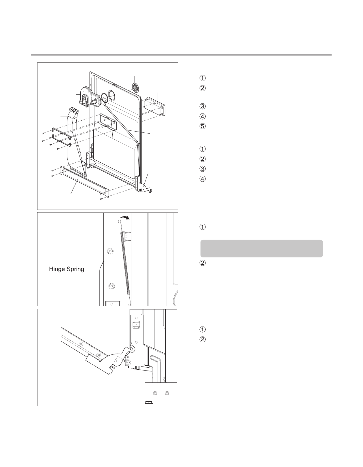
5) Door Spring (Right & Left)
Push the Spring upwards and take it off
from the the slot.
Be careful not to be injured by the
sharpedge of Tub.
Door Liner Assembly
Take off the Hinge Link from the Hinge.
6) Door Liner
Open the door.
Pull the Door Liner and take it off from
the Hinge Supporter.
Hinge Supporter
- 21 -
Page 22

Lower Frame
For Authorized Service Technician
4. Lower Frame
1) Press the holder hook as shown in figure.
2) Remove 4 screws.
3) Hold the lower frame by one hand.
Push the base cabinet inside from other hand.
Pull the lower frame out.
Lead Wire Holer
Lead Wire Holer Hook
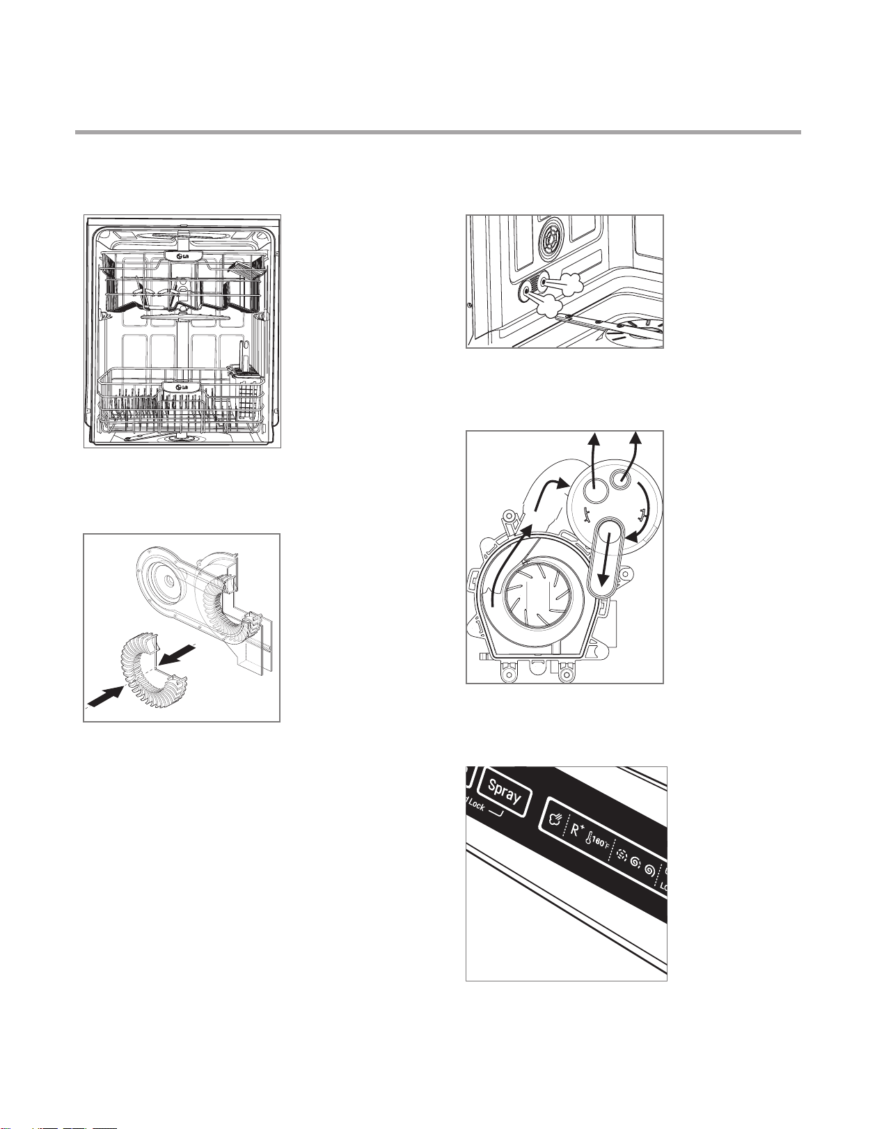
5. Tub Assembly
1) Rack
① Remove the top rack and the
upper / lower rack
2) Nozzle and Water Guide
① Pull up the nozzle.
② Remove the water guide form
the tub bracket. (Top & Rear)
.
- 22 -
Page 23

For Authorized Service TechnicianFor Authorized Service Technician
3) Sump Assembly
① Remove the wire connections.
② Remove 2 hoses assembly.
③ Rotate 2 holders between sump and tub.
④ Lift up sump assembly.
⑤ Remove the wire connections in the back
of the sump assembly.
4) Air guide Nut
.
① Turn the air guide nut counterclockwise.
(Special tool might be needed.)
Be careful the rubber packing of
air guide assembly should not be lost.
5) Tub Sub Assembly
① Remove Side 4 screws.
② Remove rear 4 screws.
③ Disconnect 1 hose assembly of left side.
(Steam nozzle hose)
④ Lift tub assembly upward.
Be careful not be injured or scratch floor
by the sharp edge of tub.
- 17 -- 17 -
- 23 -
Page 24

For Authorized Service Technician
6) Steam Nozzle
① Remove side 4 screws.
② Push the steam nozzle.
7) Holder Supporter, Tub Packing
and Hinge Supporter Assembly.
Rotate the screwdriver, after slide it into the
gap between Stopper Roller and Rail Roller.
- 24 -
Page 25

Nut
Foot
Holder
Leg Adjust
Shaft Assembly
Shaft Assembly
For Authorized Service TechnicianFor Authorized Service Technician
7) Foot & Nut
Pull the Foot twisting
Pull the Nut pushing the hook.
8) Rear Leg Adjustment System
Remove 2 screws.
Pull the Holder.
Pull the Leg Adjust.
Pull the Shaft Assembly
.
- 25 -
Page 26

For Authorized Service Technician
7. Sump Assembly
- 21 -- 21 -
1) Heater
① Remove the wire connections.
② Pull the heater out of the sump after
releasing the nut.
2) Pressure Switch & Soil Sensor
① Remove the wire connections.
② Disconnect 1 hose assembly.
③ Remove 1 screw.
④ Pull up Pressure Switch and Soil Sensor.
3) Impeller & Washing Motor
① Remove 4 screws & 1 hose assembly.
② Lift up pump assembly.
③ Remove 6 screws.
④ Remove 1 screw under a motor.
⑤ Lift up 2 pump cases.
⑥ Remove 1 screw.
⑦ Lift up impeller.
⑧ Remove 1 screw under a motor.
⑨ Lift up pump cover.
4) Vario Valve
① Remove 6 screws on the nozzle holders.
② Lift up nozzle holders.
③ Lift up Vario Valve.
5) Vario Motor & Vaio Cam
① Remove 2 screws for Vario Motor.
② Pull the Vario Motor/Cam and Micro switch.
- 26 -
Page 27

For Authorized Service TechnicianFor Authorized Service Technician
8.TROUBLE SHOOTING METHODS
7. TROUBLE SHOOTING METHODS
A. TROUBLE SHOOTING ACCORDING TO DISPLAYED ERROR MESSAGE
ERROR MESSAGE
INLET ERROR
displayed
Condition
Not reached to the normal water level in spite
of 10 min. water supply
DRAIN ERROR
displayed
Condition
Not fully drained out in
spite of 5 min. drain
operation
POSSIBLE CAUSE
FOR ERROR OCCURRENCE
The Water Supply Tap is closed.
The Water Supply is shut off.
The Inlet Hose is kinked.
The Water Pressure is very low
(below 10 psi) or high(above 120 psi)
Inlet Valve is OK?
The filter of Inlet Valve is clogged
by impure water.
The Hall sensor is OK?
The Impeller of Air Guide is bound.
The Drain Hose kinked or blocked.
Wiring connection is OK?
The drain outlet of sump is
blocked.
The Drain Pump/Motor or circuit is
troubled.
No drainage though drain pump is
working properly? Air in the
impeller of the drain pump might
cause this case.
The Air gap is clogged.
Knockout plug of garbage disposal
not removed.
Take action on Water Supply
device.
Measure the electric resistance of
Inlet Valve. (23~27
Clean the filter of Inlet Valve.
Check the frequency of Inlet Water
by the Test Mode.
Replace the Air Braker.
Remove the cause of kink or block.
Check the wiring connection.
Measure the electric resistance of
Drain Motor. (20-40
Replace the Drain Motor or repair
the Circuit.
Remove all the water remained in
the drain hose that is connected to
the drain pump / motor.
Keep the unit upright, don't lay it
down.
Cautious about leaking on the floor.
Clean the air gap.
Remove knock out plug.
REMEDY
)
)
LEAKAGE ERROR
or
displayed
Condition
The excessive RPM of
Washing Motor
happened during Wash
cycle due to water
leakage.
Water leakage in Hose connections.
Water is leaked by damages.
The Motor Water Seal leakage of
Sump assembly
The height of Drain Hose connection
(sink-Drain Hose) is not over 20
Impeller of the W
worn away
The float assembly is not working.
The lower tub gasket came
loose or fell off.
.
.
ashing Pump is
.
- 27 -
Replace the connections of Hose.
Check the point of damages and
repair or replace the related parts.
Read the Installation Instructions
(page 44) and fix it to the
recommended Height.
Replace the Impeller of the
Washing Pump.
Change the float assembly.
Replace the lower tub gasket.
※ Remove water near the Float
ASM before the repair.
Page 28

For Authorized Service Technician
ERROR MESSAGE
EXCESS ERROR
displayed
Condition
Excessive water is supplied than normal water
level.(Automatically drain
Pump operated.)
THERMAL ERROR
displayed
Condition
The resistance of thermistor not normally out put.
POSSIBLE CAUSE
FOR ERROR OCCURRENCE
The Inlet Valve is troubled.
The Controller is troubled.
The float assembly is not working
The Inlet Water Temperature is
very high. (over 194
Wiring connection is OK?
The Thermistor is OK?
)
REMEDY
Replace the Inlet Valve.
Repair or replace the Controller
Change the float assembly.
Check the temperature. (Test Mode)
If the temperature is displayed,
adjust the Inlet Water
Temperature to 120
If the temperature is not
displayed,
check the wiring connection.
check the electric resistance
of Thermistor.
(11~14k
Replace the PCB.
at 77 )
.
.
MOTOR ERROR
displayed
Condition
The Motor is working
abnormally
.
HEATER ERROR
displayed
Condition
The water is not heated or
the temperature in the Tub
is overheated to over 194ßF
VARIO ERROR
displayed
Condition
The position of vario cam is
not properly.
Wiring connection is OK?
The Impeller of Washing Pump is
locked.
The rotor of Washing Motor is
locked.
The Blade is locked.
The Circuit of Heater is troubled.
The Thermistor is troubled.
The Heater is shorted.
The Relay Circuit is troubled.
Wiring connection is OK?
Does the vario S/W assembled
properly?
Is the vario motor operated
properly?
(range is 12~15Ω)
Check the wiring connection.
Replace the cause of restriction.
Replace the Washing Motor.
Replace the PCB.
Repair the Circuit of Heater.
Replace the Thermistor.
Replace the Heater.
Repair the Relay Circuit..
Check the wiring connection.
Reassemble vario S/W.
Replace the vario motor.
.
- 28 -
Page 29

For Authorized Service TechnicianFor Authorized Service Technician
B. STEAM GENERATOR ERROR MESSAGE
Steam Generator Error mode is not displayed in normal condition and it can be confirmed
by following additional operation.
To confirm steam generator error, press the SPRAY and HALF LOAD buttons
When Steam Generator is out of order, dishwasher operates the selected cycle without
steam.
ERROR MESSAGE CONDITIONREMEDY
simultaneously.
SE0
SE1
SE3
SE4
The normal condition
The generator heater temperature
is high. (over 239
Not reached to the normal water
level.
The generator heater temperature
is low. (lower than 158
)
)
Check the water level sensor and
thermistor check.
Check the inlet valve and sensor
connection.
Check the heater and thermistor.
.
- 29 -
Page 30

7. TROUBLE SHOOTING METHODS
For Authorized Service Technician
Inlet Error
The water is supplied.
Frequency is not increased
Is the connector connected to
main PCB assembly disconnected
or disassembled? (NA8)
No
Is displayed?
Ye s
Does the water supplied?
Check the frequency of Inlet Water by
the Test Mode.
Reconnect or
Ye s
repair the connector.
Condition.
Not reached to the normal water level
in spite of 10 min. water supply.
The water is not
supplied.
Is the water tap opened? Open the water tap.
No
Ye s
Is the inlet hose kinked?
No
Repair the inlet hose.
Ye s
Is the water pressure
very low or high?
(below 0.5kgf/㎠(20bar),
above12kgf/㎠(120bar))
Ye s
Install the pressure pump.
Is the voltage between connectors
out of range? (NA8 pin1 ~ pin2)
- After remove terminal position
assurance (TPA) of connector,
check the voltage when water is injected.
(The voltage is 2.5V AC (±15%)
Is the resistance vales between
connectors out of range?
(range is over 5MΩ)
(White 8P, Pin1~Pin2)
No
Ye s
Replace the main
PCB assembly
Is the lter of inlet valve
clogged by impure water?
Is the Inlet sensor operate properly?
Blue 6P 1-2 is 12V
Inlet Valve 25±5% (Ω)
No
No
Ye s
a) Close the water tap.
b) Unscrew the inlet hose.
(Inlet valve side)
c) Clean the lter of inlet valve.
No
Replace the inlet valve
- 30 -
Page 31

Drain Error
Is displayed?
Ye s
For Authorized Service TechnicianFor Authorized Service Technician
Condition.
Not fully drained out in spite of 5 min.
drain operation.
Motor rpm is not increased.
Is the connector connected to
main PCB assembly disconnected
or disassembled? (YL3)
Ye s Ye s
No
Is the voltage between connectors
out of range? (YL3 pin1~pin2~pin3)
- After remove terminal position
assurance (TPA) of connector,
check the voltage when water is
drained. (The voltage is over 12V DC)
Ye s
Is the resistance vales between
connectors out of range?
(range is 4~5Ω)
(Yellow 3P, pin1~pin2~pin3)
Does the drain motor operate?
Check the rpm of drain motor by the
test Mode.
Reconnect or
repair the connector.
No
Replace the main
PCB assembly.
No
Replace the drain
motor
Is the lter clogged? Clean the lter
Is the outer drain hose
kinked or blocked or frozen?
Is the inner drain hose
and drain case
kinked or blocked or frozen?
Motor rpm is
increased.
No
No
Ye s
Ye s
Remove the cause of kink
or block.
Remove the cause of kink
or block.
Ye s
Is the connector connected to
drain motor disconnected
or disassembled?
Ye s
Reconnect or
repair the connector.
- 31 -
Page 32

Leakage Error
Water is not ooded
in the base.
Is or
displayed?
Ye s
Is the water ooded
in the base?
How to check.
Disassembly the lower cover.
For Authorized Service Technician
Condition.
The water level in Tub goes down
during operation or standby mode.
Water is ooded
in the base.
Is the oat assembled properly?
Replace or
Ye s Ye s
repair the oat.
Tilt the machine and drain
water in the base.
And nd the cause of
leakage.
Remove the cause of leakage.
- 32 -
Page 33

Excess Error
Is displayed?
For Authorized Service TechnicianFor Authorized Service Technician
Condition.
Excessive water is supplied than normal water
level. (Automatically drain Pump operated.)
No
Is the connector connected to
main PCB assembly disconnected
or disassembled? (NA8)
No
Is the voltage between connectors
out of range? (NA8 pin1 ~ pin2)
- After remove terminal position
assurance (TPA) of connector,
check the voltage when water is
injected.
(The voltage is 2.5V AC (±15%)
Is the water supplied when
the machine is shut down?
Ye s
Reconnect or
repair the connector.
No
Replace the main
PCB assembly
Yes
(Close the water tap.)
Does the inlet valve
working properly?
(damaged or operating
abnormally)
Ye s
Replace the inlet valve
Is the resistance vales between
connectors out of range?
(range is over 5MΩ)
(White 8P, Pin1~Pin2)
Is the Inlet sensor operate properly?
(red+black range is 8~10kΩ)
(white+black range is 15~30MΩ)
Ye s
- 33 -
Replace the inlet valve
No
Page 34

Thermal Error
Is displayed?
Ye s
For Authorized Service Technician
Condition.
The resistance of thermistor not
normally out put.
Is the connector
connected to main PCB
assembly disconnected or
disassembled? (RD6)
No
Is the resistor between
connectors out of range?
(RD6 pin2 ~ pin3)
- After remove the
connector from the PCB,
check the resistor.
(range is 12~13kΩ)
Reconnect
Ye s Yes
or repair the
connector.
Is the connector
connected to heater
assembly disconnected or
disassembled?
No
Ye s
Replace the
main PCB
assembly.
Is the thermistor operated
properly?
(range is 12~13kΩ)
Ye s
Reconnect
or repair the
connector.
Replace the
thermistor.
No
- 34 -
Page 35

Heater Error
Ye s
Is displayed?
Ye s
Is the heater resistance
Measured properly?
(range is 11~12.5Ω)
For Authorized Service TechnicianFor Authorized Service Technician
Condition.
The water is not heated
or the temperature
in the inner tub is
overheated to over 95℃
No
Is the connector connected
to main PCB assembly
disconnected or
disassembled?
(X1 : stand-by relay,
X2 : Sump Heater relay,
RD6 : Thermistor )
No
When door is closed, check
the resistor between
X1 4pin and X2 4pin.
`
Ye s
No
Reconnect or
repair the
connector.
Reconnect or
repair the
trans cable.
Does the inlet valve
working properly?
(damaged or operating
abnormally)
Ye s
- 35 -
Page 36

For Authorized Service Technician
Does the PCB assembly
working properly?
When door is closed, check
the resistor between X1 4pin
and X2 4pin.
-. Heater working
: 120V AC 15%
-. Heater stop : 0~1V
Ye s
Is the pressure S/W
operating properly?
No
Ye s
Replace the PCB
assembly
Replace the pressure S/W.
- 36 -
Page 37

Locked motor Error
Is displayed?
Ye s
For Authorized Service TechnicianFor Authorized Service Technician
Condition.
The revolution of washing motor is
not increased.
Check the connectors below.
Is the connector disconnected or
disassembled?
Main PCB assembly : RD3
Main PCB assembly : WH4
Ye s
No No
Reconnect
or repair the
connector.
Is the resistance values
in the range of 15 to 20Ω?
※ 1-2, 2-3, 3-1 pin
( After pull out the RD3 connector,
check the terminal of the connector
in wire. (Red 3P, male)
Ye s
Is the voltage between connectors
out of range?
(WH4 pin1 ~ WH4 pin4)
- After remove terminal
position assurance (TPA)
of connector, check the voltage,
when just power
on. (The voltage is 8~15V)
Ye s
Check or
replace the
motor.
Replace the
main PCB
assembly.
Is the resistance vales
short? (0~50Ω)
(After pull out the RD3
connector, check the
housing connector
(Pin1~Pin2, Pin2~Pin3,
Pin3~Pin1) individually.
No
Ye s
Replace the
main PCB
assembly.
- 37 -
No
Is the motor blocked?
No
Replace the motor.
Ye s
Remove the
cause of
block or
replace the
motor.
Page 38

Nozzle(Vario) Error
Is displayed?
Ye s
For Authorized Service Technician
Condition.
The position of vario cam is not
properly.
Check the connectors below.
Is the connector
disconnected or disassembled?
(BL4 : vario motor,
NA8 : Vario S/W sensing)
Ye s
Does the PCB assembly working
properly?
When Door is closed,
check the voltage between
BL4 pin1 and BL4 pin4.
-. Vario motor stop working
: 120V AC
-. Vario motor stop stop : 0~1V
No
Reconnect
or repair the
connector.
Does the vario S/W assembled properly?
No
Is the vario motor operated properly?
(range is 12~15K Ω)
Ye s
Ye s
Reassemble
vario S/W.
Replace the
vario motor.
Ye s
- 38 -
Page 39

No Power
For Authorized Service TechnicianFor Authorized Service Technician
Is the supplied voltage
120V AC(+10%, -15%)
Ye s
Is the current rating of multi-outlet power
strip enough?
(Avoid connecting several electric devices )
Check the
No No
fuse or reset
the circuit
breaker.
Is the connector connected to Main PCB
Assembly disconnected or disassembled?
Ye s
No
No
Alternate
with
explanation.
Is LED on while the power is on?
Reconnect
or repair the
connector.
Replace the
main PCB
assembly.
Ye s
Is nine pin wire of display
PCB Assembly broken? (CON1)
No
Ye s
Replace the
display PCB
assembly.
- 39 -
Ye s
Is the connector connected to PCB/Noise
lter disconnected or disassembled?
No
Reconnect
or repair the
connector.
Page 40

Washing result is not satisfactory.
For Authorized Service Technician
After washing, is there
any white deposits
on the dishes or inner tub?
No
After washing, is there
any streaks on the dishes
or inner tub?
No
After washing, is there
small particles (food) on the
dishes of inner tub?
No
Is the washing result of
cups & glasses not
satisfactory? (Upper basket)
No
Ye s
Ye s
Ye s
Ye s
Using a wash booster will help
remove spots, residue and hard
water (white) lm.
Reduce the amount of Rinse aid.
a) Wash lter assembly.
b) Check the rotation of spray arms.
(lower, upper, top nozzle)
a) Does the upper nozzle t properly
to the water guide?
Reassemble or replace
→
the upper nozzle or water guide
b) Does the water guide t properly
to the sump?
Reassemble or replace
→
the water guide.
Is the washing result of
utensils not satisfactory?
(Top basket)
Ye s
a) Does the top nozzle t properly
to the water guide?
Reassemble or replace
→
the top nozzle or water guide
b) Does the water guide t properly
to the sump?
Reassemble or replace
→
the water guide.
- 40 -
Page 41

Drying result is not satisfactory.
For Authorized Service TechnicianFor Authorized Service Technician
After washing, is there
any streaks on the dishes
or inner tub?
No
After washing, is there
water drops on the dishes
or inner tub?
No
Is the drying result of
cups & glasses not
satisfactory? (Upper basket)
No
Is the drying result of
utensils not satisfactory?
(Top basket)
Ye s
Ye s
Ye s
Ye s
Reduce the amount of Rinse aid.
Increase the amount of Rinse aid.
a) Does the upper nozzle t properly
to the water guide?
Reassemble or replace
→
the upper nozzle or water guide
b) Does the water guide t properly
to the sump?
Reassemble or replace
→
the water guide.
a) Does the top nozzle t properly
to the water guide?
Reassemble or replace
→
the top nozzle or water guide
b) Does the water guide t properly
to the sump?
Reassemble or replace
→
the water guide.
- 41 -
Page 42

For Authorized Service Technician
C. TROUBLE DIAGNOSES AND REPAIR BY SYMPTOM
No Power on when the power button pressed.
The Power connection
is correctly connected.
YES
The Fuse or
Circuit Breaker
of house is O.K?
YES
The Power Switch or
the Circuit is O.K?
NO
NO
NO
• Re-connect the Powr connection.
• Check the electricity is failed or not.
• Replace the Fuse or Circuit Breaker of house.
• Check the Power Switch or the circuit and repair it.
YES
Check the Controller.(Power Circuit)
- 42 -
Page 43

The Wash Pump/Motor does not run.
For Authorized Service TechnicianFor Authorized Service Technician
The Door is tightly
closed?
YES
The Wiring connections
is OK?
YES
The Blade is not locked
by a small and sharp
object?
NO
NO
NO
• close the Door tightly.
• Check the Door Switch in Latch Handle.
• Re-connect the wiring connections related to the
Washing Motor.
• Remove the cause of lock or replace the Blade.
YES
Replace the Wahing Pump/Motor
- 43 -
Page 44

Washing Results are not Satisfactory
For Authorized Service Technician
After washing, are there still
White deposits or streaks on
the dishes?
NO
After washing, are there still
food soils on the dishes?
YES
Check that : - the amount of detergent Correctly used or not
- Filters clogged or not.
- the holes of spray arms blocked or not.
- Utensils are correctly arranged or not.
- Utensils are overloaded or not.
- the spray arm rotating is obstructed or not.
- the program is correctly selected or not.
YES
Reduce the amount of Rinse-Aid
(for Streak)
Dry Results are not satisfactory
Increase the amount of Rinse-Aid.(Set the number higher)
Select the Program that the Rinse temperature is higher.
- 44 -
Page 45

For Authorized Service TechnicianFor Authorized Service Technician
Power Button not automatically off after operation.
Check the button is blocked by foreign materials.
Check the Power Switch.(Replace it, if necessary.)
Check the Controller.(Replace it, if necessary.)
- 45 -
Page 46

For Authorized Service Technician
9. INSTALLATION INSTRUCTION
Figure A
Step 2: PREPARE THE ELECTRICAL WIRING
1. This appliance must be operated with correct voltage as shown in this manual and on the
rating plate, and connected to an individual, properly grounded branch circuit, protected
by time delay fuse. Wiring must be 3 wires including ground.
2. The wiring or cord should be in an accessible location adjacent to, and not behind the
dishwasher and within 4 ft. (1.2m) of the dishwasher side.
3. The wiring or cord must be grounded properly, if in doubt, have it checked by a qualified
electrician. No other appliance shall be connected to the same outlet by a double adapter
or similar plug.
4. The wiring or cord must be oriented as shown in Figure A below.
5. Check the dishwasher for any damage before trying to install it.
6. Make sure water line and Electrical line are oriented in the bottom channels as shown in
the figure below.
If you find any damage to the dishwasher, Please contact your dealer or builder
immediately.
WARNING
For personal safety, remove house fuse or open circuit breaker before installation.
Do not use an extension cord or adapter plug with this dishwasher.
Electrical and grounding connections must comply with the national electrical
code/provincial and municipal code and/or other local codes.
8. INSTALLATION INSTRUCTION
Step 1: PREPARE CUPBOARD OPENING
1. This dishwasher is designed to fit a standard dishwasher opening as shown below.
2. Select a location as close to sink as possible for easy connections to water and drain lines.
3. The dishwasher should not be installed more than 10 ft. (3m) from the sink for proper
drainage.
4. If dishwasher is to be installed in a corner, a minimum of 2 in. (50mm) is required between
the dishwasher and an adjacent a wall.
If dishwasher will sit directly on
subflooring, subfloor should be
sealed with a waterproof paint or
sealer to prevent damage from
steam.
Drill a 1-1/2 (38mm) dia hole or cut
out for drain hose, inlet hose and
electrical cables on either side.
approx. 4 (100mm, W) X 4 (100mm, H)
These openings must be within 4
(100mm) from the floor and 1-5/8
(40mm) from the back wall. If there is
a floor in the cabinet under the sink,
it will also be necessary to drill or cut
through the floor to connect the
water and drain under the sink.
Ensure the floor under the dishwasher is at the same level as the rest of the room to
allow for any service requirements.
- 46 -
Page 47

For Authorized Service TechnicianFor Authorized Service Technician
Step 2: PREPARE THE ELECTRICAL WIRING
WARNING
For personal safety, remove house fuse or open circuit breaker before installation.
Do not use an extension cord or adapter plug with this dishwasher.
Electrical and grounding connections must comply with the national electrical
code/provincial and municipal code and/or other local codes.
1. This appliance must be operated with correct voltage as shown in this manual and on the
rating plate, and connected to an individual, properly grounded branch circuit, protected
by time delay fuse. Wiring must be 3 wires including ground.
2. The wiring or cord should be in an accessible location adjacent to, and not behind the
dishwasher and within 4 ft. (1.2m) of the dishwasher side.
3. The wiring or cord must be grounded properly, if in doubt, have it checked by a qualified
electrician. No other appliance shall be connected to the same outlet by a double adapter
or similar plug.
4. The wiring or cord must be oriented as shown in Figure A below.
5. Check the dishwasher for any damage before trying to install it.
6. Make sure water line and Electrical line are oriented in the bottom channels as shown in
the figure below.
If you find any damage to the dishwasher, Please contact your dealer or builder
immediately.
Figure A
- 47 -
Page 48

For Authorized Service Technician
1. Remove the Lower Cover and orient dishwasher as shown below.
2. Before sliding the dishwasher into the cupboard opening, make all necessary height
adjustments using the legs.
3. Slide the dishwasher into the cabinet opening carefully. Make sure that the drain hose
inside the cabinet is not kinked.
4. Follow the instruction as in Figure B.
Step 5: INSTALL THE DISHWASHER IN CUPBOARD
Step 3: PREPARE THE WATER SUPPLY CONNECTION
1. This dishwasher may be connected to either hot or cold water. If the water can not be
maintained below 149
2. When connecting the dishwasher water line, sealing tape or compound should be used to
avoid leaks.
3. When connecting the dishwasher water line, the house supply should be shut off.
4. The Water Supply Tube must be oriented as shown in Figure A on page 6.
Step 4: PREPARE DISHWASHER FOR INSTALLATION
(65 ), the dishwasher must be connected to cold water.
1. Adjust the legs to the required height to fit properly under the countertop as shown below.
2. Check the level of dishwasher by using level.
Left side – turn the
adjusting screw
counterclockwise to lower
the leg and raise the rear
of the dishwasher.
Right side – turn the
adjusting screw clockwise
to lower the leg and raise
the rear of the dishwasher.
Front feet can be adjusted
from the top using a 1/4
square drive wrench.
- 48 -
Page 49

For Authorized Service TechnicianFor Authorized Service Technician
Step 5: INSTALL THE DISHWASHER IN CUPBOARD
1. Remove the Lower Cover and orient dishwasher as shown below.
2. Before sliding the dishwasher into the cupboard opening, make all necessary height
adjustments using the legs.
3. Slide the dishwasher into the cabinet opening carefully. Make sure that the drain hose
inside the cabinet is not kinked.
4. Follow the instruction as in Figure B.
- 49 -
Page 50

For Authorized Service Technician
Step 7: WATER SUPPLY CONNECTION
1. When connecting, sealing tape or
sealing compound should be
used to avoid water leaks.
2. Before connecting, turn off the water
supply.
3. After fitting the Elbow into the
Inlet Valve, slide the Flexible
Stainless Tube or Copper Tube
into the Elbow.
4. Tighten the nut and make sure
that the line is not kinked or
sharply bent.
Inlet Valve
Water Supply Tube
Elbow
1. Before beginning, turn off electrical
power to the unit at the circuit breaker.
2. Remove the Junction Cover and then
Install the Strain Relief.
3. Twist Wire Connectors tightly on the
wires. Wrap each connection with
Electrical tape.
4. Check again and make sure that all
wires are connected correctly, black to
black, white to white, green to green
(ground to ground).
5. Replace the Junction Cover.
Junction Box
Junction Cover
Step 8: ELECTRICAL POWER CONNECTION
Step 6: DRAIN LINE CONNECTION
1. If the end of the drain hose does not fit to the drain line, use an adapter (not supplied) that
must be resistant to heat and detergent and may be obtained from a plumbing shop.
2. There are 2 typical connections as shown in Figures C & D.
There may be other options than shown here for connection the drain hose. The drain
connection must meet local plumbing regulations.
The S trap spigot must be drilled out cleanly and free of obstruction to its maximum
internal diameter, if used for drainage.
To prevent syphoning, one of the following instruction methods must be followed:
Figure C:
Connection to Disposer or waste Tee.
Figure D:
Connection to Air Gap.
Drain Requirements
Follow local codes and ordinances.
Do not exceed 10 ft. (3m) distance
to drain.
Do not connect drain lines from
other devices to the dishwasher
drain hose.
- 50 -
Page 51

Step 7: WATER SUPPLY CONNECTION
1. When connecting, sealing tape or
sealing compound should be
used to avoid water leaks.
2. Before connecting, turn off the water
supply.
3. After fitting the Elbow into the
Inlet Valve, slide the Flexible
Stainless Tube or Copper Tube
into the Elbow.
4. Tighten the nut and make sure
that the line is not kinked or
sharply bent.
Water Supply Tube
Inlet Valve
For Authorized Service TechnicianFor Authorized Service Technician
Elbow
Step 8: ELECTRICAL POWER CONNECTION
1. Before beginning, turn off electrical
power to the unit at the circuit breaker.
2. Remove the Junction Cover and then
Install the Strain Relief.
3. Twist Wire Connectors tightly on the
wires. Wrap each connection with
Electrical tape.
Junction Cover
4. Check again and make sure that all
wires are connected correctly, black to
black, white to white, green to green
(ground to ground).
5. Replace the Junction Cover.
Junction Box
- 51 -
Page 52

For Authorized Service Technician
Step 9: FINAL CHECKS
1. Turn electrical power back on at the circuit breaker.
2. Turn house water supply back on.
3. Operate the dishwasher through one cycle (Quick cycle is recommended) to check for
water leaks and operating conditions.
4. Replace the Lower Cover.
- 52 -
Page 53

10. EXPLODED VIEW
9. EXPLODED VIEW
For Authorized Service TechnicianFor Authorized Service Technician
“The following parts are not illustrated"
Printed
materials
*Owner’s Manual
*Service Manual
Description
- 53 -
Loc No.
G001
G004
Page 54

EXPLODED VIEW
EXPLODED VIEW
For Authorized Service Technician
LDT9965/LDF8874
E005
F101
F001
A040
E010
A003
A130
E005
M050
- 54 -
M051
M052
M053
M054
Page 55

EXPLODED VIEW
EXPLODED VIEW
For Authorized Service TechnicianFor Authorized Service Technician
LDF8764
F101
F001
E005
E010
A040
A003
E005
M050
- 55 -
M051
M052
A130
M053
M054
Page 56

EXPLODED VIEW
EXPLODED VIEW
For Authorized Service Technician
LDF7774 / LDS5774
F001
E005
E010F101
A040
ACCESSORIES
A003
E005
M050
- 56 -
M051
M052
A130
M053
M054
Page 57

EXPLODED VIEW - TUB ASSEMBLY
EXPLODED VIEW - TUB ASSEMBLY
For Authorized Service Technician
LDT9965/LDF8874
F110
F060
F022
F041
F171
F011
F013
F144
F040
F050
F230
F300
F112
F118
F113
F117
F111
F117
F111
F210
F113
F132
F105
M006
F137
F117
F166
M071
M070
F138
- 57 -
F165
F011
F013
F143
F117
F215
Page 58

EXPLODED VIEW - TUB ASSEMBLY
EXPLODED VIEW - TUB ASSEMBLY
For Authorized Service Technician
LDF7774 / LDS5774
F110
F060
F040
F050
F022
F041
F171
F011
F013
F144
F112
F118
F113
F117
F111
F117
F111
F210
F113
F132
F105
M006
F137
F117
F166
M071
M070
F138
F165
- 58 -
F143
F117
F215
F011
F013
Page 59

EXPLODED VIEW - TUB ASSEMBLY
EXPLODED VIEW - TUB ASSEMBLY
F060
F040
For Authorized Service TechnicianFor Authorized Service Technician
LDF8764
F041
F171
F011
F013
F132
F022
F144
F137
F050
F230
F300
F143
F105
M006
F117
M071
F166
F138
M070
- 59 -
F165
F011
F013
F117
F215
Page 60

EXPLODED VIEW - BASE ASSEMBLY
EXPLODED VIEW - BASE ASSEMBLY
For Authorized Service Technician
LDT9965/LDF8874/LDF8764
F047
M500
M210
M100
F046
M090
A160
M260
M105
F148
F149
M266
- 60 -
Page 61

EXPLODED VIEW - BASE ASSEMBLY
EXPLODED VIEW - BASE ASSEMBLY
For Authorized Service TechnicianFor Authorized Service Technician
LDF7774 / LDS5774
F148
M210
M100
M105
M090
A160
M260
F149
M266
- 61 -
Page 62

EXPLODED VIEW - RACK ASSEMBLY
EXPLODED VIEW - RACK ASSEMBLY
For Authorized Service Technician
A159
A156
A151
A157
A158
A145
A070
A101
A102
A103
A150
A060
A165
A080
A155
F192
F004
F005
A141 A147 A146 A142
A140
- 62 -
A050
F191
A110
Page 63

EXPLODED VIEW - CUTLERY RACK ASSEMB LY
LDT9965/LDF8874/LDF7774/LDS5774
EXPLODED VIEW - CUTLERY RACK ASSEMBLY
A170
A171
For Authorized Service Technician
A172
A152
- 63 -
Page 64

LDT9965/LDF8874/LDF8764/LDF7774
EXPLODED VIEW - PANEL / DOOR ASSEMBLY
K260
K207
K280
K270
For Authorized Service Technician
K215
K280
K222
K005
K010
K254
K230
K100
K124
K002
K110
K121
K251
K122
K101
K001
K141
K140
F142
F141
K030
F174
- 64 -
Page 65

EXPLODED VIEW - PANEL / DOOR ASSEMBLY
For Authorized Service TechnicianFor Authorized Service Technician
LDS5774
K200
K030
K212
K006
K100
K262
K254
K280
K110
K121
K260
K252
K251
K122
K101
K001
K217
K124
K002
K
F174
K141
K140
F142
F141
- 65 -
Page 66

EXPLODED VIEW - SUMP ASSEMBLY
For Authorized Service Technician
A120
M071
M081
M089
M091
M072
M074
M075
M070
M125
M120
M025
M126
M087
M031
M028
M006
M060
M130
M131
M132
M026
M027
M030
M088
M133
M134
- 66 -
Page 67

For Authorized Service Technician
10. WIRING DIAGRAM
BN
YL
BL
RD
NO NO
NO NO
COM COM
X3
X2
1 2 3 4 5 6 7 8 9
NA9
1 2 3 4 5 6 7 8 9
1 2 3 4 5 6 7 8 9
10 9 8 7 6 5 4 3 2 1
BK
WH
NO NO
COM COM
COM COM
X1
RD6
1 2 3 4 5 6
NA8
1 2 3 4 5 6 7 8
GY
BK
1 2 3
WH
RD
BK
BL
1 2 3 4 5 6
YL
Float
S/W
YL
1 2 3 4 5 6 7 8
120 ± 10%
SB
BN
WH
BK
BL
VT
3 2 1
BL
(LDT9965,LDF8874,LDF8764 Series)
YL
BN
5 Vdc
Sensor
Turbidity
RD6
BL to RD
(Sump)
2 1
BK
1 2
Vac
Vario
2 1
Flow
Meter
12~13
Thermistor
RD
Rinse
Refill
Vac
S/W
120 ± 10%
(Steam)
49 ± 5%
Thermistor
NA8
12 Vdc
7~13
VT to BL
BL to VT
BL(2) to BL(3)
RD
BL
BK
Vac
S/W
Pressure
120 ± 10%
BK
YL
11 ~ 12.5 Ω
Sump Heater
X1 WH to X2 BL
Stop : 0 ~ 1 V ac
Working : 120 ± 10% V ac
BK
Vac
S/W
Pressure
120 ± 10%
BK
BN
BK
Steam Heater
BN
120 ± 10% Vac
L
N
1
3
2
1
3
2
BK
WH
Error Message
• IE – INLET ERROR
• OE – DRAIN ERROR
• AE or E1 – LEAKAGE ERROR
• FE – EXCESS ERROR
• tE - THERMAL ERROR
• LE – MOTOR ERROR
• HE – HEATER ERROR
• nE – VARIO ERROR
RD1
0 Ω
Fuse
Noise Filter
Test Mode
WH1 BK to RD1 BK
WH1 WH to RD1 BN
Component Tests
WH1
• Ohm Tests wit h connectors removed
• Press Del ay Start 1Time to 12Times
• Voltage Tests wi th connectors installed
• Press Auto & Heavy & POWER
NOTES
Power Code
120 Vac / 60Hz
WH
YL3
1 2 3
11 10 9 8 7 6 5 4 3 2 1
Main PCB
PK
WH
GY
VT
BL
GN
YL
OR
RD
BN
1 2 3 4 5 6 7 8 9 10 11
BK
GY WH
VT
BL
GN
YL
OR
RD
BN
1 2 3 4 5 6 7 8 9 10
BK
Display PCB Display PCB
Power Button
BK
BN
RD
OR
YL
6 5 4 3 2 1
GN
NA6
1 2 3 4 5 6
1 2 3 4 5 6
LED Supporter
BL6
1 2 3 4 5 6
BL4 WH4
1 2 3 4
YL4
1 2 3 4
1 2 3 4
RD3
1 2 3
Note : All Switch are Normally Closed / Press Butt on & Switch OPENS!
U V W
BL
1 2 3
1 2 3 4 5 6
1 2 3 4
YL/
1 2 3 4
1 2 3 4
1 2 3
1 2 3
SB
GY
YL
BL
OR
RD
BL
GY
RD
1
VT
GN
BL
RD
SB
BL
WH
1 2
YL3
4~5 Ω
Drain
BLDC
Motor
U V W
Inlet V/V
BL
1 2 1 2
Inlet V/V
)
5 Vdc 5 Vdc
Level
Wash
Steam
(High
Level
Wash
(Low)
Steam
WH
SB to BL
BL to WH
WH to SB
COM
Door
S/W
(1/2)
120 ± 10%
-ser
1 2
Dispen
RD
BL6
12 Vdc
OR to BL
(Sump)
(Steam)
RD
25 ± 5% Ω
BL6
12 Vdc
RD to BL
25 ± 5% Ω
RD
RD
NO
NC
Vac
NO
COM
BN
NC
Vac
Door
S/W
(2/2)
120 ± 10%
BL
YL
GY
Vario
1 2
Motor
12 ~ 15
Working : 120 ± 10% V ac
Fan
Motor
120± 5% Ω
120 ± 10% Vac
RD
Vcc
N
BK
GY
VT
BL
SB
1 2 3 4 5 6 7
U V W Ha Hb G
WH
Wiring Color Legend
BK – Black BL – Blue BN – Brown GN – Green GY – Gray
OR – Orange PK – Pink RD – Red SB – Sky Blue WH – W hite
V – V iolet YL - Yellow
BL4
RD to BL
Stop : 0 ~ 1 V ac
osition
D
Wash
motor
Function Test while operating;
WH4
8 ~ 15 Vdc
RD3
5~20 Ω
Press Auto & Dual Control = Water Temp.
Press Auto & Heavy = Water Supply Frequency
Press Auto & Delicate = Steam Temp.
Press Auto & Delicate & Power = IPM Temp.
Press Dual Cont rol & Heavy = Wash Motor RPM
Press Quick & Dry & Extra Dry = Drain Motor RPM
VT to BK (Pulsing Signal)
RD to BK (Voltage Input)
GY to BK (Pulsing Signal )
BL to SB
WH to BL
SB to WH
Press Dual Cont rol & Normal = Vario P
- 67 -
Page 68

For Authorized Service Technician
(LDF7774, LDS5774 Series)
BN
BN
BL
NO NO
X2
NA9
1 2 3 4 5 6 7 8 9
1 2 3 4 5 6 7 8 9
10 9 8 7 6 5 4 3 2 1
11 10 9 8 7 6 5 4 3 2 1
Main PCB
BK
WH
NO NO
COM COM
COM COM
X1
RD6
1 2 3 4 5 6
7 8
NA8
1 2 3 4 5 6
YL3
1 2 3
BL6
1 2 3 4 5 6
GY
5 Vdc
Sensor
BK
1 2 3
Turbidity
WH
RD
BK
2 1
BK
BL
1 2 3 4 5 6
YL
Float
S/W
YL
SB
7 8
BN
BL
VT
1 2 3 4 5 6
1 2 3
1 2 3 4 5 6
3 2 1
BL
WH
BL
SB
GY
YL
Rinse
1 2
Vac
Vario
S/W
120 ± 10%
Flow
Meter
12 Vdc
BLDC
Drain
Motor
1 2 3
U V W
BL
OR
RD6
BL to RD
(Sump)
12~13
Thermistor
Refill
RD
Vac
120 ± 10%
NA8
7~13
VT to BL
BL to VT
BL(2) to BL(3)
YL3
4~5 Ω
SB to BL
BL to WH
WH to SB
-ser
1 2
Dispen
BL6
12 Vdc
1 2
OR to BL
(Sump)
25 ± 5% Ω
Inlet V/V
BL
BK
Pressure
BK
Sump Heater
BK
Pressure
BK
WH
COM
NC
Vac
Door
S/W
(1/2)
120 ± 10%
NO
RD
RD
Door
S/W
(2/2)
BN
Error Message
• IE – INLET ERROR
• OE – DRAIN ERROR
BK
BN
L
N
1
3
S/W
Vac
120 ± 10%
11 ~ 12.5 Ω
X1 WH to X2 BL
Stop : 0 ~ 1 Vac
Working : 120 ± 10% Vac
Vac
S/W
120 ± 10%
RD
NO
COM
NC
Vac
120 ± 10%
2
RD1
0 Ω
Fuse
Noise Filter
WH1 WH to RD1 BN
WH1
1
3
2
BK
WH
Power Code
120 Vac / 60Hz
BN
• AE or E1 – LEAKAGE ERROR
Test Mode
WH1 BK to RD1 BK
• Press Half Load & Delay Start & POWER
NOTES
• Press Auto & Heavy & POWER
Wiring Color Legend
BK – Black BL – Blue BN – Brown GN – Green GY – Gray
OR – Orange PK – Pink RD – Red SB – Sky Blue WH – White
• FE – EXCESS ERROR
• tE - THERMAL ERROR
• LE – MOTOR ERROR
• HE – HEATER ERROR
• nE – VARIO ERROR
Component Tests
• Press Delay S tart 1Time to 9Times
• Voltage Tests with connectors installed
• Ohm Tests with connectors removed
V – Violet YL - Yellow
PK
WH
GY
VT
BL
GN
YL
OR
3 4 5 6 7 8 9 10 11 1 2 3 4 5 6 7 8 9
RD
BN
BK
GY WH
VT
BL
GN
YL
OR
RD
BN
1 2 3 4 5 6 7 8 9 10 1 2
BK
Display PCB Display PCB
Power Button
BK
BN
RD
OR
YL
6 5 4 3 2 1
GN
NA6
1 2 3 4 5 6
1 2 3 4 5 6
LED Supporter
BL4 WH4
RD3
Note : All Switc h are Normally Closed / Press Button & Switch OPENS!
BL
GY
1 2 3 4
1 2 3 4
RD
1 2 3 4
1 2 3 4
SB
BL
1 2 3
1 2 3
U V W
WH
BL
1 2
YL
GY
RD
BK
GY
VT
BL
SB
WH
BL4
Vario
Fan
1 2 3 4 5 6 7
RD to BL
Motor
12 ~ 15
Stop : 0 ~ 1 Vac
Working : 120 ± 10% Vac
Motor
120 ± 5% Ω
120 ± 10% Vac
Vcc
N
D
Wash
motor
U V W Ha Hb G
Function Test while operating;
WH4
8 ~ 15 Vdc
RD3
5~20 Ω
Press Auto & Dual Control = Water Temp.
Press Auto & Heavy = Water Supply Frequency
Press Dual Control & Heavy = Wash Motor RPM
Press Quick & Dry & Extra Dry = Drain Motor RPM
Press Dual Control & Normal = Vario Position
VT to BK (Pulsing Signal)
RD to BK (Voltage Input)
GY to BK (Pulsing Signal)
BL to SB
WH to BL
SB to WH
Press Auto & Delicate & Power = IPM Temp.
- 68 -
Page 69

For Authorized Service TechnicianFor Authorized Service Technician
- 69 -
Page 70

For Authorized Service Technician
- 70 -
P/No. : MFL37554813
 Loading...