

LG LD-2120WHU, LD-2140WHU, LD-2140WMHU, LD-2143WTHU, LD-2143WHU Service Manual
...
DISHWASHER
SERVICE MANUAL
BEFORE SERVICING THE UNIT, PLEASE READ THIS MANUAL CAREFULLY
FOR SAFETY AND CORRECT SERVICES.
NOTE
MODEL : LD-2120W(M)HU
LD-2140W(M)HU
LD-2143W(
T
)HU

- 3 -
1. CAUTION......................................................................................................................... 4
2. SPECIFICATIONS........................................................................................................... 5
3. FEATURES & TECHNICAL EXPLANATION ................................................................... 6
4. PARTS NAME................................................................................................................ 10
5. WIRING DIAGRAM...................................................................................................... 11
6. PROGRAM CHART (SCHEMATIC DIAGRAM)............................................................ 12
7. HOW TO DISASSEMBLE ............................................................................................ 13
8. TROUBLE SHOOTING METHODS.............................................................................. 23
A. TROUBLE SHOOTING ACCORDING TO DISPLAYED ERROR MESSAGE.......... 23
B. TROUBLE DIAGNOSES AND REPAIR BY SYMPTOM........................................... 25
9. INSTALLATION INSTRUCTION ................................................................................... 29
10. EXPLODED VIEW .......................................................................................................33
CONTENTS

- 4 -
DISCONNECT POWER CORD BEFORE SERVICING
RECONNECT ALL GROUNDING DEVICES
IMPORTANT SAFETY NOTICE !
This service information is intended for individuals
possessing adequate backgrounds of electrical,
electronic and mechanical experience.
Any attempt to repair this appliance may result in
personal injury and property damage.
The manufacturer or seller can not be responsible
for the interpretation of this information, nor can it
assume any liability in connection with its use.
CAUTION !
- 5 -
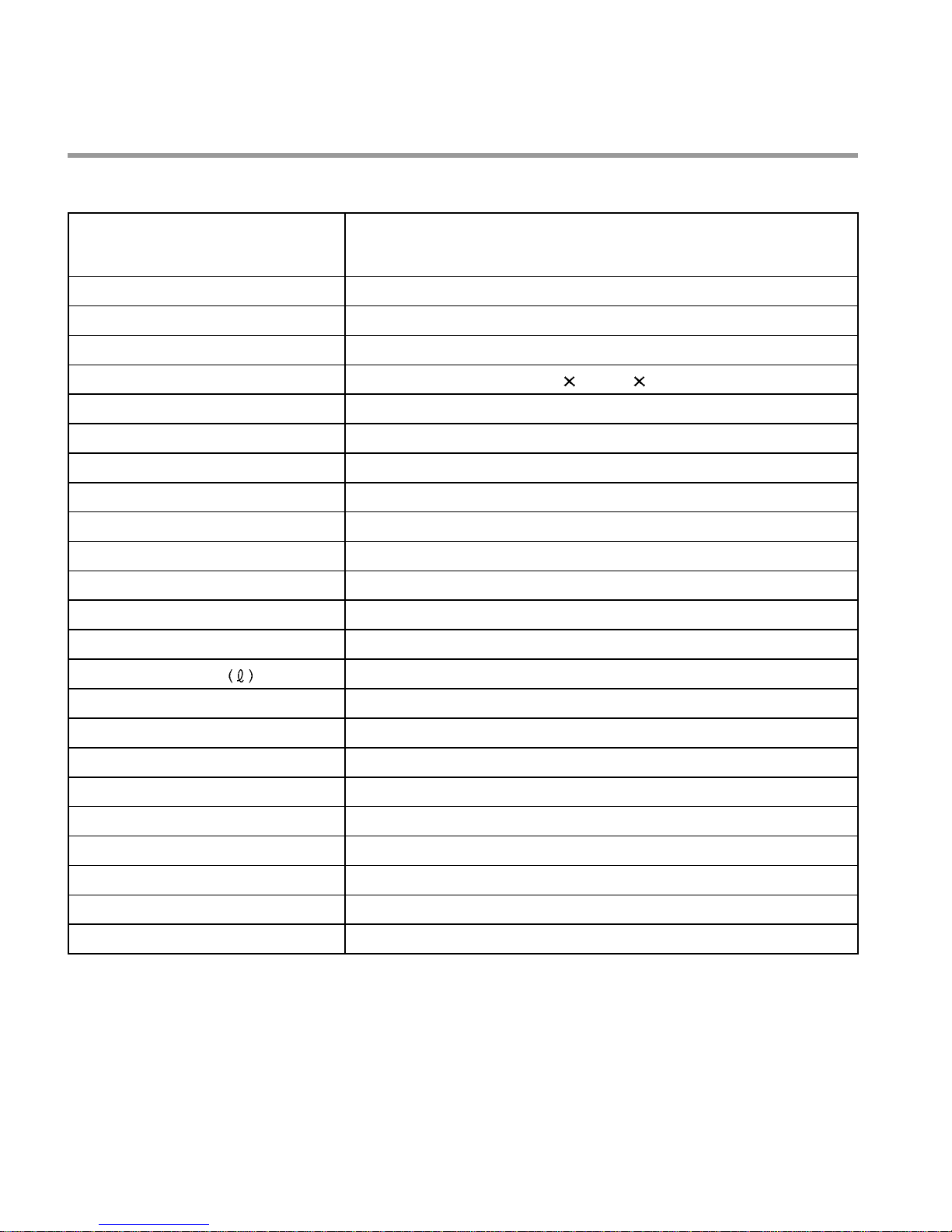
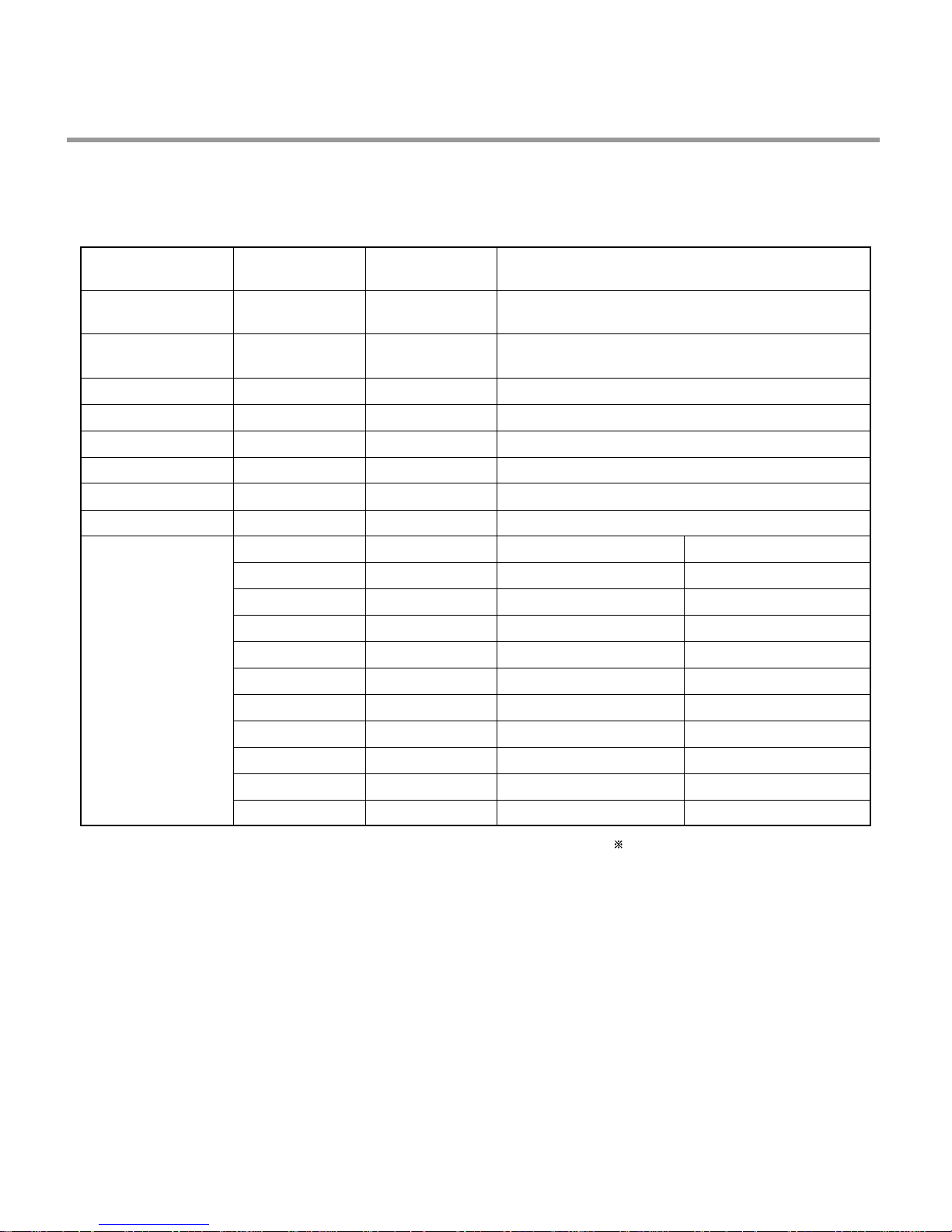
2. SPECIFICATION
Rated Voltage / Frequency AC 230V/50Hz
Installation Built-under
Place Settings 12
Product Dimension(mm) 598(W)
580(D) 817(H)
Product Weight(Kg) 48
Door Colour White / Silver / Titanium
Tub Material Stainless Steel
Control Electronic
Rated Power(Watt) 2,210
Heater Power(Watt) 2,100
Programs 212 series : 4 / 214 series : 5
Upper Rack Position Adjustable
Lower Rack 50% Fold down
Water Consumption
15 (Eco)
Power Consumption (kWh) 1.05 (Eco)
Operating Time (min) 115(Except Drying):Eco
Fan Dry System Yes
Delay Start Function Yes
Auto-Off Power Switch Yes
Process Monitor No
Wash Level 5
Racks Nylon Coating
Operating Water Pressure (Bar) 0.5 ~ 8
ITEM
SPECIFICATION
- 6 -
3. FEATURES & TECHNICAL EXPLANATION
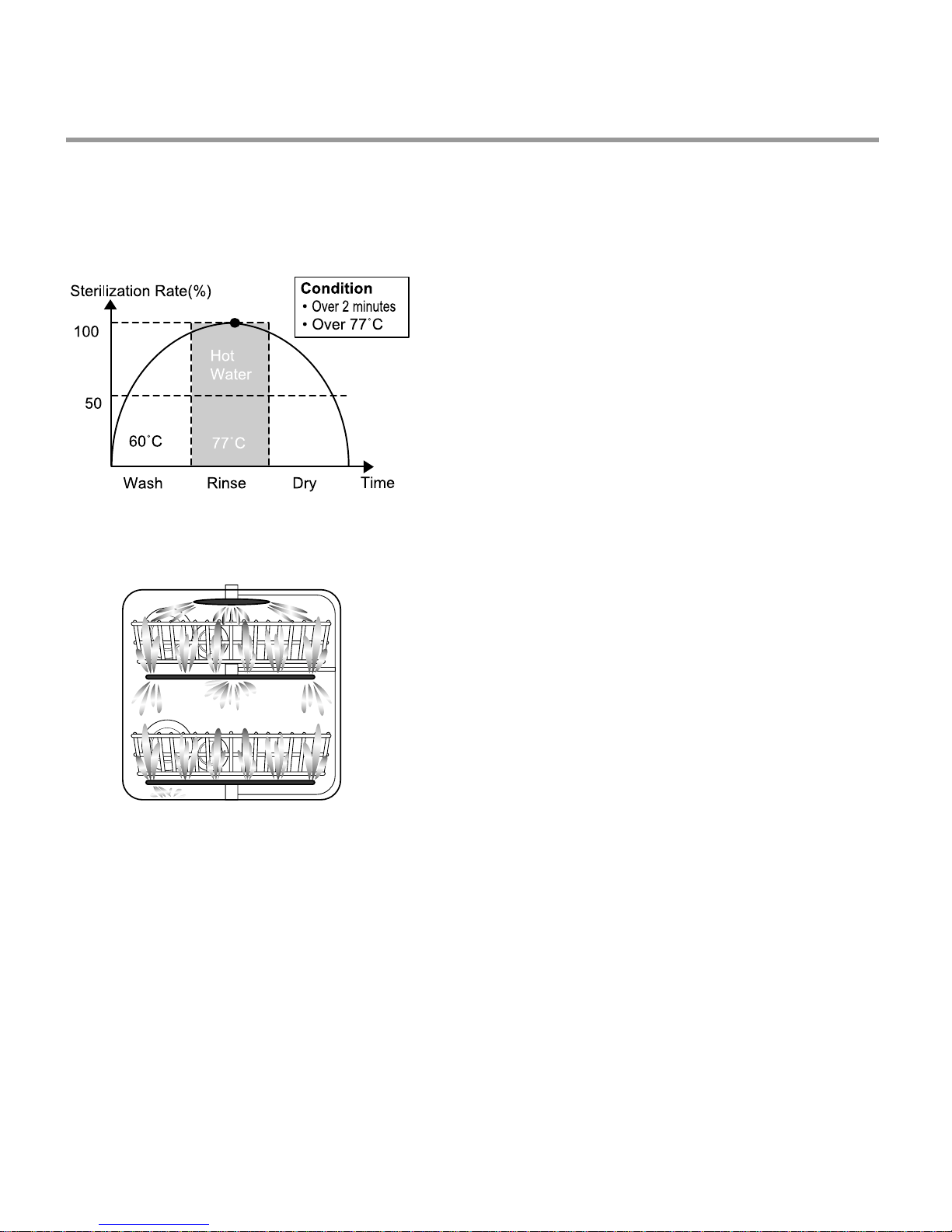
3-1 New Technology Introduction
• During the high temp. Rinse course, water
temperature in an dishwasher reaches 77°C,
considerably higher than the average rinse
temperature in conventional
dishwashers(65°C). This is how Rinse 77°C
can eliminate some bacteria such as
salmonella.
3-1-1. High Temperature Rinsing (LD-213/214 series only)
• Turbo Spray System is elaborately designed to
achieve a more powerful and efficient wash.
You can see the excellent 3 rotating spray arm
with 5 directional waterjet.
3-1-2. Turbo Spray System
- 7 -
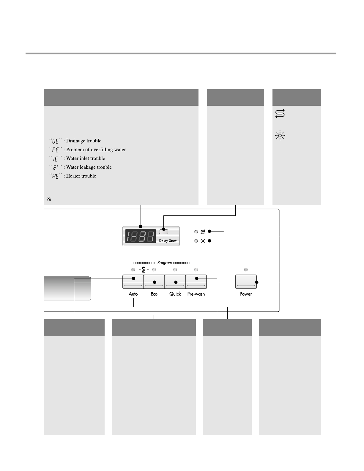
3-2. Display Panel
3-2-1. LD-212 Series
TIME LEFT
• Before starting, the display window shows the running time of
the selected program.
• After starting, the display window shows the remaining time.
• If the dishwasher has a trouble, the trouble type is displayed.
If this error letters are displayed, please refer to the trouble
shooting guide page 26~27 and follow the guide.
“ ” : No error message (See page 27)
DELA Y START
• If you want to delay
the start of selected
program, press this
button before
pressing program
button.
• Pressing the delay
time will increase
time by 1 hour.
• The delay start time
can be adjusted from
1 hour to 19 hours.
INDICATOR
• Refill with
special salt
• Refill with
rinse aid
CHILD LOCK
• Used to lock or unlock
the control buttons to
prevent all the setting
from being changed
by a
child.automatically
canceled when power
failure occur.
• For locking/
unlocking, press Auto
and Eco button for a
few seconds
simultaneously .
BEEP ON/OFF
• The dishwasher must be
switched off.
• The beep on/off function can be
set by pressing the Quick and
Pre-wash button
simultaneously for a few
seconds. then, a “on” will appear
in the time display .
• The beep on/off function is
automatically canceled when
power failure occur.
PROGRAM
• When you want
to select
program, press
each button.
POWER
• For operating, press
this button first for
power on.
• After operating, this
button automatically
switches off for safety
and energy saving.
• In case of irregular
surge disturbance to
the machine, the power
may be automatically
turned off for safety.
- 8 -
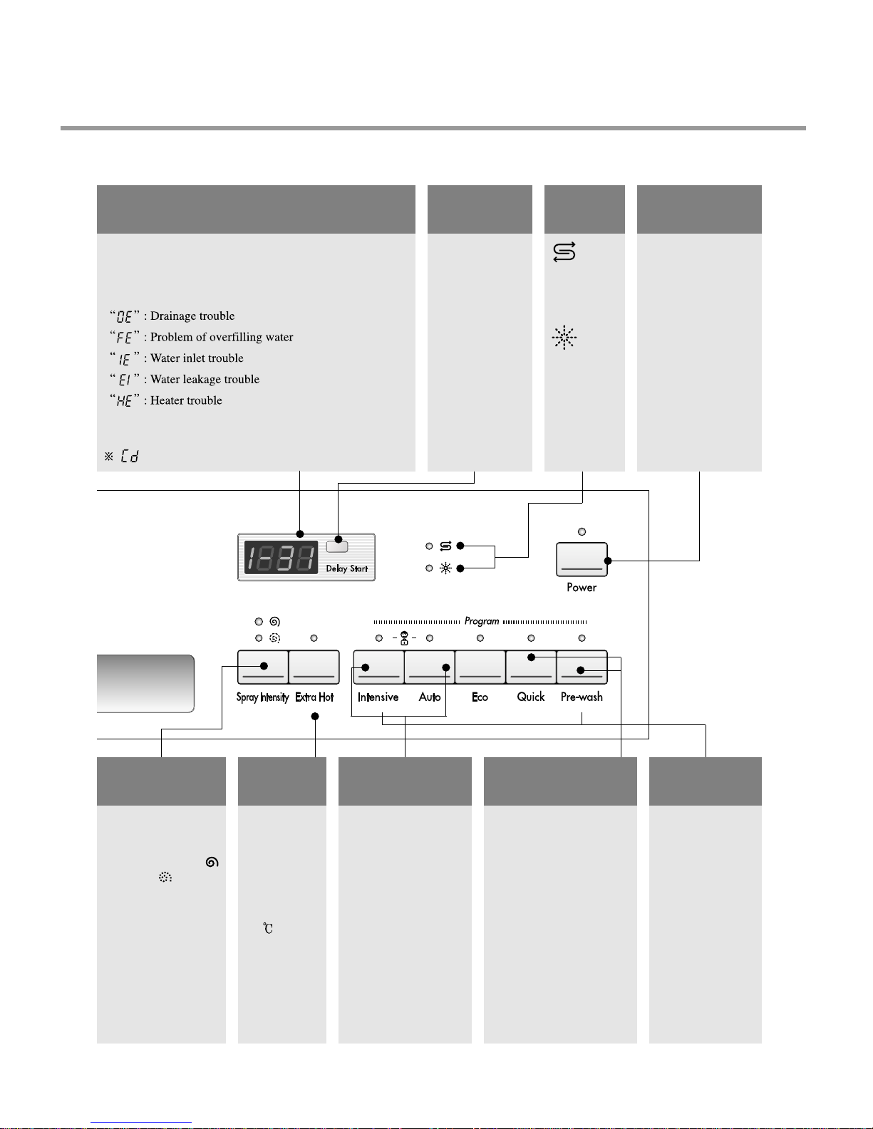
3-2-2. LD-214 Series
TIME LEFT
• Before starting, the display window shows the running time of
the selected program.
• After starting, the display window shows the remaining time.
• If the dishwasher has a trouble, the trouble type is displayed.
If this error letters are displayed, please refer to the trouble
shooting guide page 26~27 and follow the guide.
“ ” : No error message (See page 27)
DELAY
START
• If you want to
delay the start of
selected program,
press this button
before pressing
program button.
• Pressing the delay
time will increase
time by 1 hour.
• The delay start
time can be
adjusted from 1
hour to 19 hours.
SPRAY
INTENSITY
• With each press, the
level of water jet is
changed to “Strong- ”
and “Soft- ”
EXTRA
HOT
• When select
Extra Hot
function, the
operating
temperature
will be up to
77 .
BEEP ON/OFF
• The dishwasher must be
switched off.
• The beep on/off function
can be set by pressing the
Quick and Pre-wash
button simultaneously for a
few seconds. then, a “on”
will appear in the time
display .
• The beep on/off function is
automatically canceled when
power failure occur.
PROGRAM
• When you want to
select program,
press each button.
POWER
• For operating, press
this button first for
power on.
• After operating, this
button automatically
switches off for safety
and energy saving.
• In case of irregular
surge disturbance to
the machine, the
power may be
automatically turned
off for safety.
INDICA
TOR
• Refill
with
special
salt
• Refill
with
rinse
aid
CHILD LOCK
• Used to lock or unlock
the control buttons to
prevent all the setting
from being changed by
a child.automatically
canceled when power
failure occur.
• For locking/ unlocking,
press Intensive and
Auto button for a few
seconds simultaneously.
3.3 TEST MODE
CHECK PROGRAM(START IN THE STATE OF THE CLOSED DOOR)
BUTTON
The number of
pushing button
DISPLAY Load and Checking points
Auto + Quick +
POWER S/W
Half Load KEY
(Spray Intensity Key)
Extra Hot KEY
Intensive
Auto KEY
Eco KEY
Quick KEY
Pre-wash KEY
Time Delay Key
1 TIME
1 TIME
1 TIME
1 TIME
1 TIME
1 TIME
1 TIME
1 TIME
1 TIME
2 TIME
3 TIME
4 TIME
5 TIME
6 TIME
7 TIME
8 TIME
9 TIME
10 TIME
11 TIME
n : 0H
11 : 11
12 : 22
13 : 33
14 : 44
15 : 55
16 : 66
17 : 77
n : 01
n : 02
n : 03
Frequency
n : 05
n : 06
Temperature
n : 08
n : 09
n : 0A
n : 0b
All LEDs are lighting
All LEDs are lighting
All LEDs are lighting
All LEDs are lighting
All LEDs are lighting
All LEDs are lighting
All LEDs are lighting
All LEDs are lighting
None
Washing motor
Drain pump
Inlet valve
Dispenser
Heater(for 10 sec.)
Fan motor
Regeneration Valve
Lower Nozzle
Upper Nozzle
Auto OFF S/W
Salt Refill
Rinse Refill
Upper(Strong)
Lower(Soft)
Extra Hot
Intensive
Auto
Eco
Quick
Pre-wash
Micro S/W must be ON to operate HEATER
- 9 -
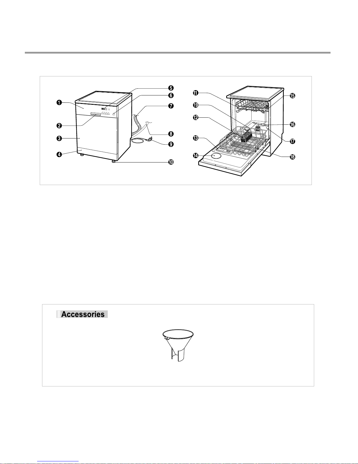
4. PARTS NAME
- 10 -
1. Control Panel
2. Door Handle
3. Front Cover
4. Lower Cover
5. Process Monitor
6. Power Switch
7. Drain hose
8. Inlet hose
9. Power Cord
10. Adjust Leg
11. Upper Rack
12. Cutlery Rack
13. Detergent & Rinse Aid Dispenser
14. Vapor Vent Cover
15. Upper Spray Arm
16. Lower Spray Arm
17. Filter ASM
18. Lower Rack
19. Salt Container Cap
※ The appearance and specifications may be varied without notice according to localities.
Funnel
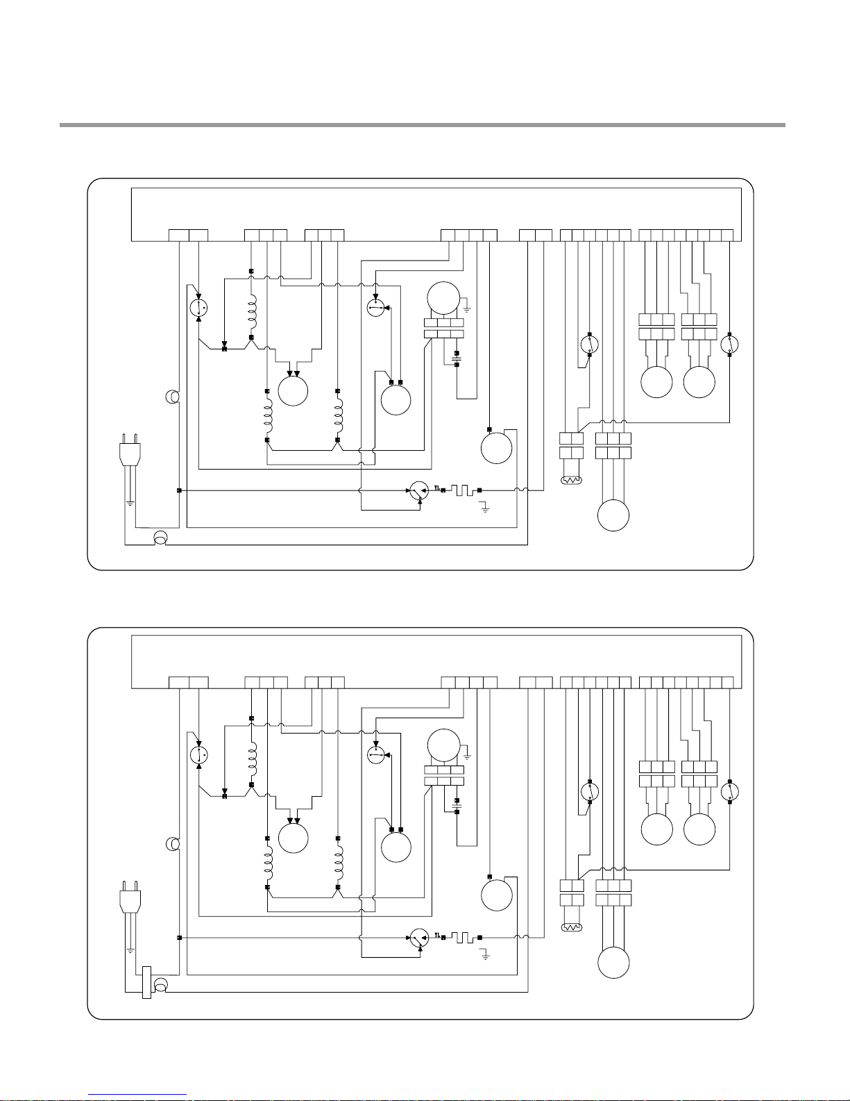
5. WIRING DIAGRAM
CONTROLLER
RD YL BL BL WH WH
Tap Relay
YL
WH
INLET VALVE
FERRITE CORE
REGEN. VALVE
RD
RD
GY
GY
FAN
VT
BL
BL
BL
BN
BN
BN
GN/YL
WH
OR
BK
BK
RDRDWH WHBK BK
BK BK BKRDWH
THERMISTER
TURBIDITY
SENSOR
SOFTENER
FLOAT
FLOW
METER
YL
WH BL RD
DOOR
S/W
VARIO
S/W
VARIO
MOTOR
CAPACITOR
RINSE+
FLOAT SWITH
WASH
PUMP
DRAIN
PUMP
HEATER
HEATER S / W
DISPENSER
FERRITE CORE
BN BL OR OR VT WH BL BLORBN BN YL BK
BK
RD RD
RD
OR
WH WHGY
GY
GY
BL BL BLGY
111 1
1
12 1
123 123
123 123
23
12 123
23
123
1 123456782345622 233 34No
Com
2
1. LD-212 Series
CONTROLLER
RD YL BL BL WH WH
Tap Relay
YL
WH
INLET VALVE
FERRITE CORE
NOISE FILTER
REGEN. VALVE
RD
RD
GY
GY
FAN
VT
BL
BL
BL
BN
BN
BN
GN/YL
WH
OR
BK
BK
RDRDWH WHBK BK
BK BK BKRDWH
THERMISTER
TURBIDITY
SENSOR
SOFTENER
FLOAT
FLOW
METER
YL
WH BL RD
DOOR
S/W
VARIO
S/W
VARIO
MOTOR
CAPACITOR
RINSE+
FLOAT SWITH
WASH
PUMP
DRAIN
PUMP
HEATER
HEATER S / W
DISPENSER
FERRITE CORE
BN BL OR OR VT WH BLORBN BN YL BK
BK
RD RD
RD
OR
WH WHGY
GY
GY
BL BL BLGY
111 1
1
12 1
123 123
123 123
23
12 123
23
123
1123456782345622 233 34No
Com
2
2. LD-214 Series
- 11 -
- 12 -
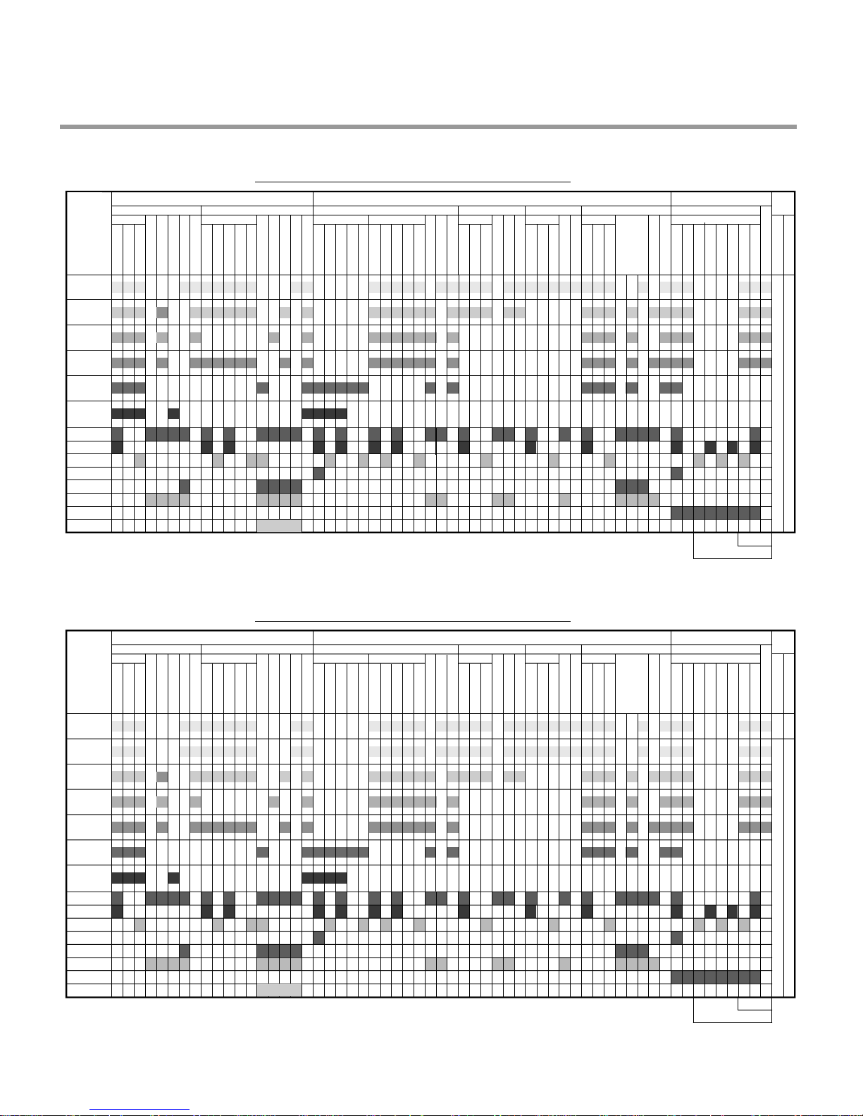
6. PROGRAM CHART(SCHEMATIC DIAGRAM)
Program chart (LD-212 Series)
Regen. Valve
Dispenser
Vario Motor
Fan Motor
Heater
Inlet Valve
Quick
Pre-Wash
Eco
Auto(Ⅲ)
Auto(Ⅱ)
Auto(Ⅰ)
Program
50 70 70
65
69
69
40
60
55
45
35
Wash
Pre Wash Main Wash Rinse 1 Rinse 2 Rinse 3 Heating Rinse Dry
Drain A Drain C Drain D Drain E Drain A Drain A Drain A Drain B
Water Supply
Water Supply
Water Supply
Water Supply
Water Supply
Water Supply
Water Supply
Water Supply
Water Supply
Water Supply
Water Supply
Wash
Wash
Wash
Wash
Wash A
Wash B
Wash C
Wash D
Rinse
Rinse
Rinse
Rinse
Heating A
Heating B
Buzz
OFF
Stop
Stop
Stop
Stop
Rinse
Stop
Stop
Stop
Stop
Stop
Stop
Stop
Stop
Stop
Drain
Drain
Drain
Drain
Drain
Drain
Drain
Drain
Drain
Drain
Water Supply
Drain
Water Supply
keeping
Drain
Dry
Drain
Drain
Rinse Dry
Finish
Drain Pump
W/ Moter
After 1 min.
H1-H4
H5-H7
Program chart (LD-214 Series)
Regen. Valve
Dispenser
Vario Motor
Fan Motor
Heater
Inlet Valve
Quick
Pre-Wash
Eco
Auto(Ⅲ)
Auto(Ⅱ)
Auto(Ⅰ)
Program
50 70 70
Intensive
50 70 70
65
69
69
40
60
55
45
35
Wash
Pre Wash Main Wash Rinse 1 Rinse 2 Rinse 3 Heating Rinse Dry
Drain A Drain C Drain D Drain E Drain A Drain A Drain A Drain B
Water Supply
Water Supply
Water Supply
Water Supply
Water Supply
Water Supply
Water Supply
Water Supply
Water Supply
Water Supply
Water Supply
Wash
Wash
Wash
Wash
Wash A
Wash B
Wash C
Wash D
Rinse
Rinse
Rinse
Rinse
Heating A
Heating B
Buzz
OFF
Stop
Stop
Stop
Stop
Rinse
Stop
Stop
Stop
Stop
Stop
Stop
Stop
Stop
Stop
Drain
Drain
Drain
Drain
Drain
Drain
Drain
Drain
Drain
Drain
Water Supply
Drain
Water Supply
keeping
Drain
Dry
Drain
Drain
Rinse Dry
Finish
Drain Pump
W/ Moter
After 1 min.
H1-H4
H5-H7
- 13 -
BEFORE DISASSEMBLING THE DISHWASHER ;
1) Remove the plug from electric outlet to avoid electric shock.
2) Close the Water Tap(faucet).
3) Remove all dishes and items in the dishwasher.
4) Remove the Lower Rack and the Upper Rack.
5) In case of the water softner assembly model, open the water softner cap to flow out the
water to sump and drain to avoid the floor wet.
6) If necessary, remove the inlet hose and drain hose to avoid the hose damages.
7) Prepare some towels to avoid floor wet by the water left in the dishwasher.
7. HOW TO DISASSEMBLE
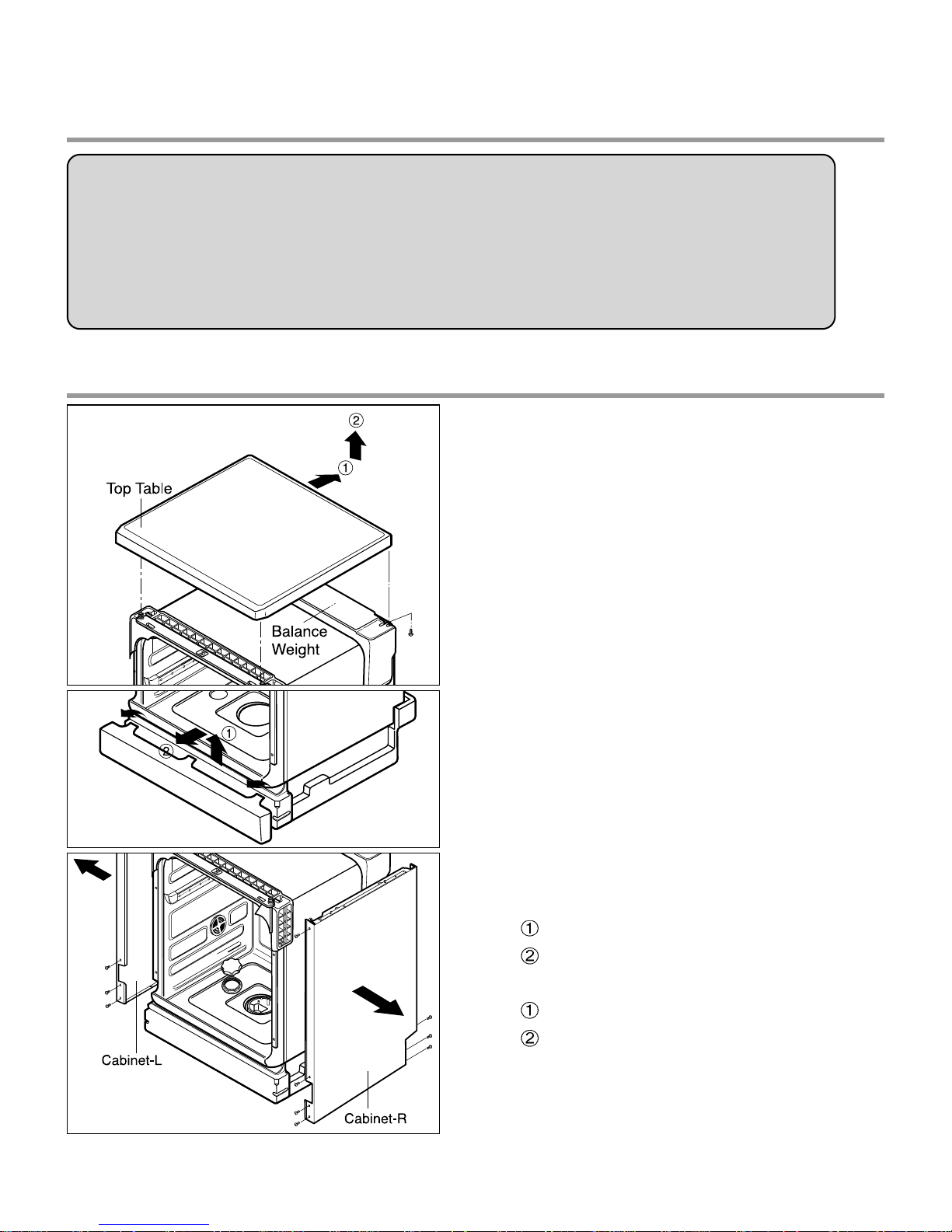
7-1. FULL DISASSEMBLE
1. Top Table
1) Remove the rear 2 screws.
2) Pull and lift the top table.
2. Low Cover
3. Cabinet-R/L
1) Cabinet-R
Remove front 4 screws.
Remove rear 3 screws.
2) Cabinet-L
Remove front 4 screws.
Remove rear 3 screws.
- 14 -
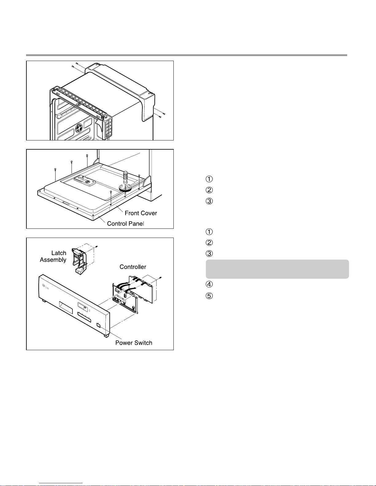
4. Balance weight
1) Remove side 4 screws.
2) Lift the balance weight.
5. Door Assembly
1) Front Cover
Open the door.
Remove 6 screws(stainless).
Close the door slowly and remove front
cover downwards.
2) Control Panel Assembly
Open the door.
Remove 4 screws(stainless).
Remove wire connection.
Be sure the wiring should not be
changed in reassembling.
Remove 3 screws for Latch assembly
Remove 3 screws for Controller.
 Loading...