

LG LD-4050W, LD-14AW2, LD-14AT2, LD-14AW3, LD-14AT3 Service Manual

DISHWASHER
SERVICE MANUAL
NOTE
BEFORE SERVICING THE UNIT, PLEASE READ THIS MANUAL CAREFULLY
FOR SAFETY AND CORRECT SERVICES.
MODEL : LD-4050W
LD-14AW2 / LD-14AT2
LD-14AW3 / LD-14AT3

CONTENTS
1. CAUTION....................................................................................................................................4
2. SPECIFICATIONS.....................................................................................................................5
3. FEATURES & TECHNICAL EXPLANATION.....................................................................6
4. PARTS NAME.........................................................................................................................11
5. WIRING DIAGRAM...........................................................................................................13
6. PROGRAM CHART (SCHEMATIC DIAGRAM)............................................................15
7. HOW TO DISASSEMBLE ...................................................................................................17
8. TROUBLE SHOOTING METHODS.....................................................................................27
A. TROUBLE SHOOTING ACCORDING TO DISPLAYED ERROR MESSAGE.........27
B. TROUBLE DIAGNOSES AND REPAIR BY SYMPTOM ..........................................29
9. INSTALLATION INSTRUCTION.....................................................................................33
10. EXPLODED VIEW ..............................................................................................................38
11. REPLACEMENT PART LIST ............................................................................................44
- 3 -

CAUTION !
�
DISCONNECT POWER CORD BEFORE SERVING
�
RECONNECT ALL GROUNDING DEVICES
IMPORTANT SAFETY NOTICE !
This service information is intended for individuals
possessing adequate backgrounds of electrical,
electronic and mechanical experience.
Any attempt to repair this appliance may result in
personal injury and property damage.
The manufacturer or seller can not be responsible
for the interpretation of this information, nor can it
assume any liability in connection with its use.
- 4 -
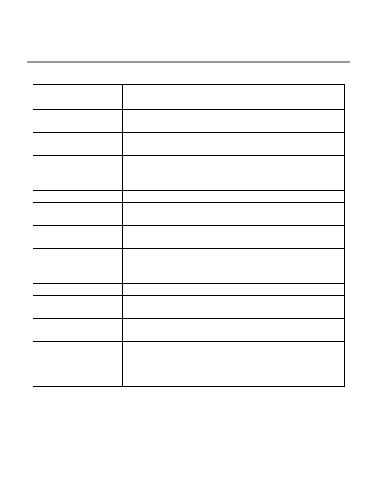
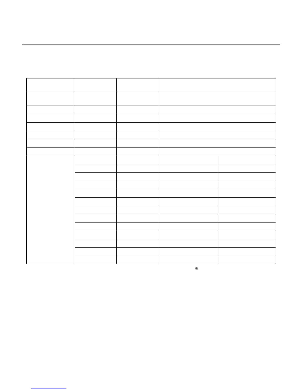
2. SPECIFICATION
ITEM
Model
Rated Voltage / Frequency
Installation
Place Settings
Product Dimension(mm)
Product Weight(Kg)
Door Colour
Tub Material
Control
Rated Power(Watt)
Heater Power(Watt)
Programs
Upper Rack Position
Lower Rack
LD-4050W LD-14AW2LD-14AT2
AC 240V/50Hz
Free Standing / built-In
14
600(W)× 600(D)× 850(H)
52
White
Stainless Steel
Electronic(Fussy)
2,210
2,100
6
Sliding Adjustable
100% Fold down
SPECIFICATION
AC 240V/50Hz
Free Standing / built-In
14
600(W)× 600(D)× 850(H)
52
Stainless Steel
Stainless Steel
Electronic
2,210
2,100
6
Sliding Adjustable
100% Fold down
AC 240V/50Hz
Free Standing / built-In
14
600(W)× 600(D)× 850(H)
52
White
Stainless Steel
Electronic
2,210
2,100
6
Adjustable
50% Fold down
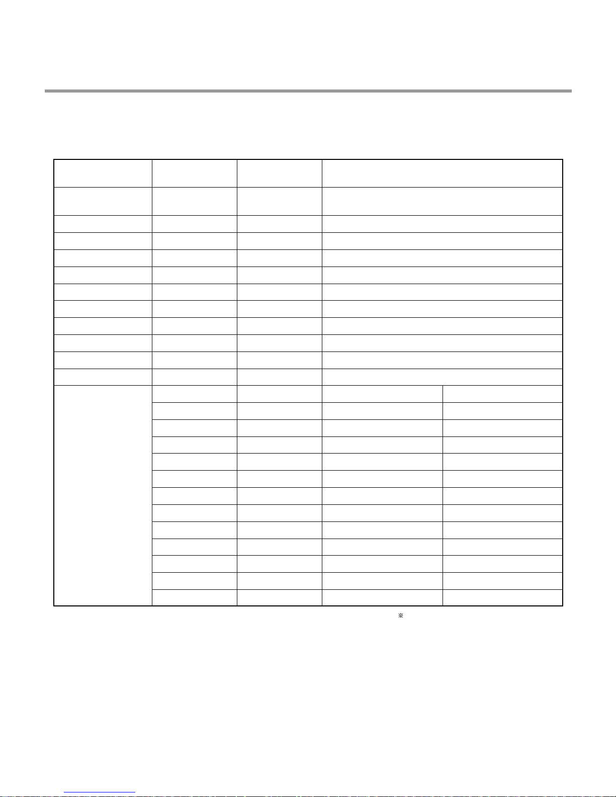
Water Consumption(ℓ)
Power Consumption (kWh)
Operating Time (min)
Fan Dry System
Delay Start Function
Auto-Off Power Switch
Process Monitor
Wash Level
Racks
Operating Water Pressure (Bar)
18 (Economy)
0.7 (Economy)
84 (Economy)
Yes
Yes
Yes
Yes
5
Nylon Coating
0.5 ~ 8
18 (Economy)
0.7 (Economy)
84 (Economy)
Yes
Yes
Yes
Yes
5
Nylon Coating
0.5 ~ 8
18 (Economy)
0.7 (Economy)
84 (Economy)
Yes
Yes
Yes
Yes
5
Nylon Coating
0.5 ~ 8
- 5 -
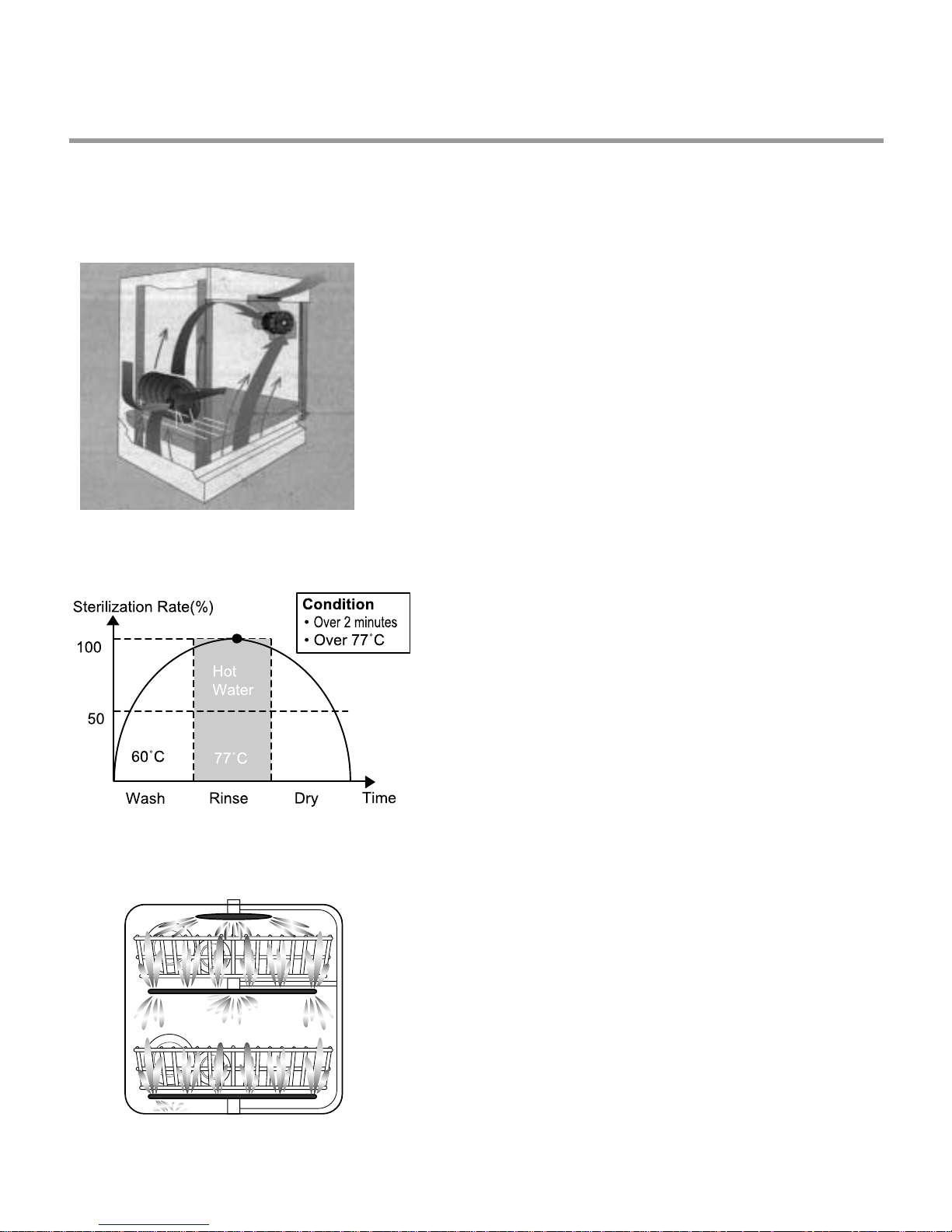
3. FEATURES & TECHNICAL EXPLANATION
3-1 New Technology Introduction
3-1-1. Turbo Fan Drying System
• Turbo fan drying system expels out hot and
humid air to enhance quick and effective
drying.
3-1-2. High Temperature Rinsing
3-1-3. Turbo Spray System
• During the high temp. Rinse course, water
temperature in an dishwasher reaches 77°C,
considerably higher than the average rinse
temperature in conventional
dishwashers(65°C). This is how Rinse 77°C
can eliminate some bacteria such as
salmonella.
• Turbo Spray System is elaborately designed to
achieve a more powerful and efficient wash.
You can see the excellent 3 rotating spray arm
with 5 directional waterjet.
- 6 -
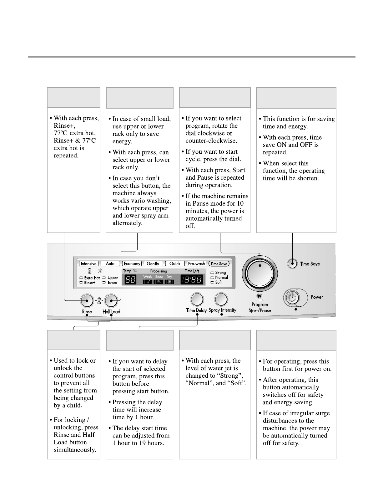
3-2. Display Panel
LD-4050W
RINSE /
EXTRA HOT
HALF LOAD
DIAL (PROGRAM &
START / PAUSE)
TIME SAVE
CHILD LOCK TIME DELAY SPRAY INTENSITY POWER
- 7 -
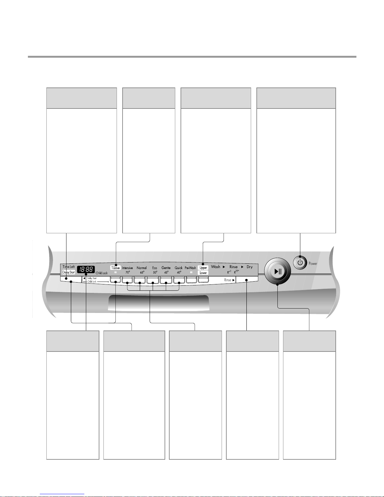
3-2. Display Panel
LD-14AW2 / LD-14AT2
DELAY START
BUTTON
• If you want to delay the
start of selected program,
press this button before
pressing start button.
• Pressing the delay time
will increase time by
1 hour.
• The delay start time can
be adjusted from 1 hour
to 19 hours.
TIME SAVE
• This function is
for saving time
and energy .
• With each press,
time save ON and
OFF is repeated.
• When select this
function, the
operating time will
be shorten.
HALF LOAD
• In case of small load, use
upper or lower rack only
to save energy .
• With each press, can
select upper or lower rack
only .
• In case you don’t select
this button, the machine
always works vario
washing, which operate
upper and lower spray
arm alternately .
POWER SWITCH
BUTTON
• For operating, press this
button first for power on.
• After operating, this button
automatically switches off for
safety and energy saving.
• If case of irregular surge
disturbances to the machine,
the power may be
automatically turned
off for safety .
REMAINING
TIME
• Indication of
remaining time
• Self diagnosis
and error
message display
CHILD LOCK
• Used to lock or
unlock the control
buttons to prevent
all the setting from
being changed by a
child.
• For
locking/unlocking,
press Delay Start
and T-Save button
simultaneously.
PROGRAM
• When power is
on, program is
automatically set
to normal.
• If you want to
change the
program, press
the button and
set the program
you want to.
- 8 -
RINSE/SANI
• With each press,
rinse+, rinse+ &
77。C sani rinse,
77。C sani rinse
is repeated.
START/PAUSE
BUTTON
• With each press,
Start and Pause
is repeated
during
operation.
• If the machine
remains in
Pause mode for
10 minutes, the
power is
automatically
turned off.
3.3 TEST MODE
CHECK PROGRAM(START IN THE STATE OF THE CLOSED DOOR)
LD-4050W
BUTTON
Half Load+Time
Delay+POWER S/W
Rinse
Half Load
Time Delay
Multi Spray
Time Save
Dial knob
Start/Pause
The number of
pushing button
1 TIME
1 TIME
1 TIME
1 TIME
1 TIME
1 TIME
1 Rotation
1 TIME
2 TIME
3 TIME
4 TIME
5 TIME
6 TIME
7 TIME
8 TIME
9 TIME
10 TIME
11 TIME
12 TIME
13 TIME
DISPLAY Load and Checking points
n : 0H
11 : 11
12 : 22
13 : 33
14 : 44
15 : 55
11 : 11 ~ 16 : 66
n : 01
Frequency
n : 03
n : 04
n : 05
n : 06
n : 07
n : 08
n : 09
Temperature
n : 11
n : 12
Water level sensor
Washing motor
Drain pump
Inlet valve
Dispenser
Heater(for 10 sec.)
Fan motor
Thermister
Lower Nozzle
Upper Nozzle
All LEDs are lighting
All LEDs are lighting
All LEDs are lighting
All LEDs are lighting
All LEDs are lighting
All LEDs are lighting
The LED of each course is lighting
None
None
AUTO OFF S/W
Micro S/W must be ON to operate HEATER
Intensive
Auto
Economy
Gentle
Quick
Pre-wash
Time Save
Wash
Rinse
Dry
Lower
Upper
- 9 -
3.3 TEST MODE
CHECK PROGRAM(START IN THE STATE OF THE CLOSED DOOR)
LD-14AT2/LD-14AW2
BUTTON
Normal+Eco
+POWER S/W
Delay Start Key
T-Save Key
Intensive Key
Normal Key
Eco Key
Gentle Key
Quick Key
Pre-Wash Key
Half & Vario Key
Rinse Key
Start/Pause
The number of
pushing button
1 TIME
1 TIME
1 TIME
1 TIME
1 TIME
1 TIME
1 TIME
1 TIME
1 TIME
1 TIME
1 TIME
1 TIME
2 TIME
3 TIME
4 TIME
5 TIME
6 TIME
7 TIME
8 TIME
9 TIME
10 TIME
11 TIME
12 TIME
13 TIME
DISPLAY Load and Checking points
n : 0H
11 : 11
12 : 22
13 : 33
14 : 44
15 : 55
11 : 11 ~ 16 : 66
17 : 77
18 : 88
19 : 99
10 : 00
n : 01
Frequency
n : 03
n : 04
n : 05
n : 06
n : 07
n : 08
n : 09
Temperature
n : 11
n : 12
Water level sensor
Washing motor
Drain pump
Inlet valve
Dispenser
Heater(for 10 sec.)
Fan motor
Thermister
Lower Nozzle
Upper Nozzle
All LEDs are lighting
All LEDs are lighting
All LEDs are lighting
All LEDs are lighting
All LEDs are lighting
All LEDs are lighting
All LEDs are lighting
All LEDs are lighting
All LEDs are lighting
All LEDs are lighting
All LEDs are lighting
None
None
AUTO OFF S/W
Micro S/W must be ON to operate HEATER
Time Save
Intensive
Normal
Eco
Quick
Pre-wash
Wash 1
Wash 2
Rinse 1
Rinse 2
Dry
- 10 -

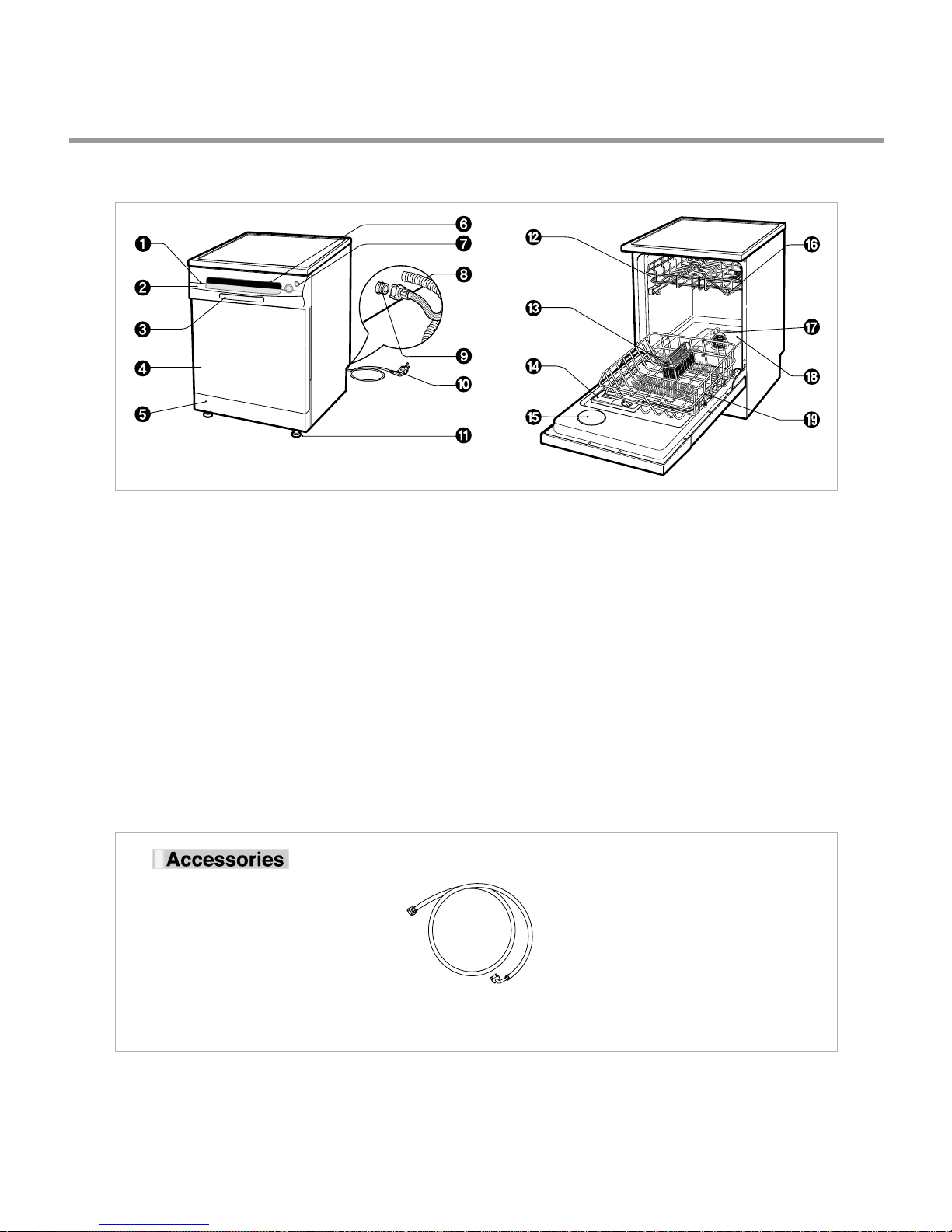
4. PARTS NAME
LD-4050W
1. Control Panel
2. Vapor vent
3. Door Handle
4. Front Cover
5. Lower Cover
6. Process Monitor
7. Power Switch
8. Drain hose
9. Inlet valve ASM
10. Power Cord
11. Adjust Leg
12. Upper Rack
13. Cutlery Rack
14. Detergent & Rinse Aid Dispenser
15. Vapor Vent Cover
16. Upper Spray Arm
17. Lower Spray Arm
18. Filter ASM
19. Lower Rack
Inlet Hose
- 11 -
4. PARTS NAME
LD-14AT2/LD-14AW2
1. Vapor vent
2. Control Panel
3. Door Handle
4. Front Cover
5. Lower Cover
6. Process Monitor
7. Power Switch
8. Inlet valve ASM
9. Drain Hose Connector
10. Power Cord
11. Adjust Leg
12. Upper Rack
13. Cutlery Rack
14. Detergent & Rinse Aid Dispenser
15. Vapor Vent Cover
16. Upper Spray Arm
17. Lower Spray Arm
18. Filter ASM
19. Lower Rack
Inlet Hose
- 12 -
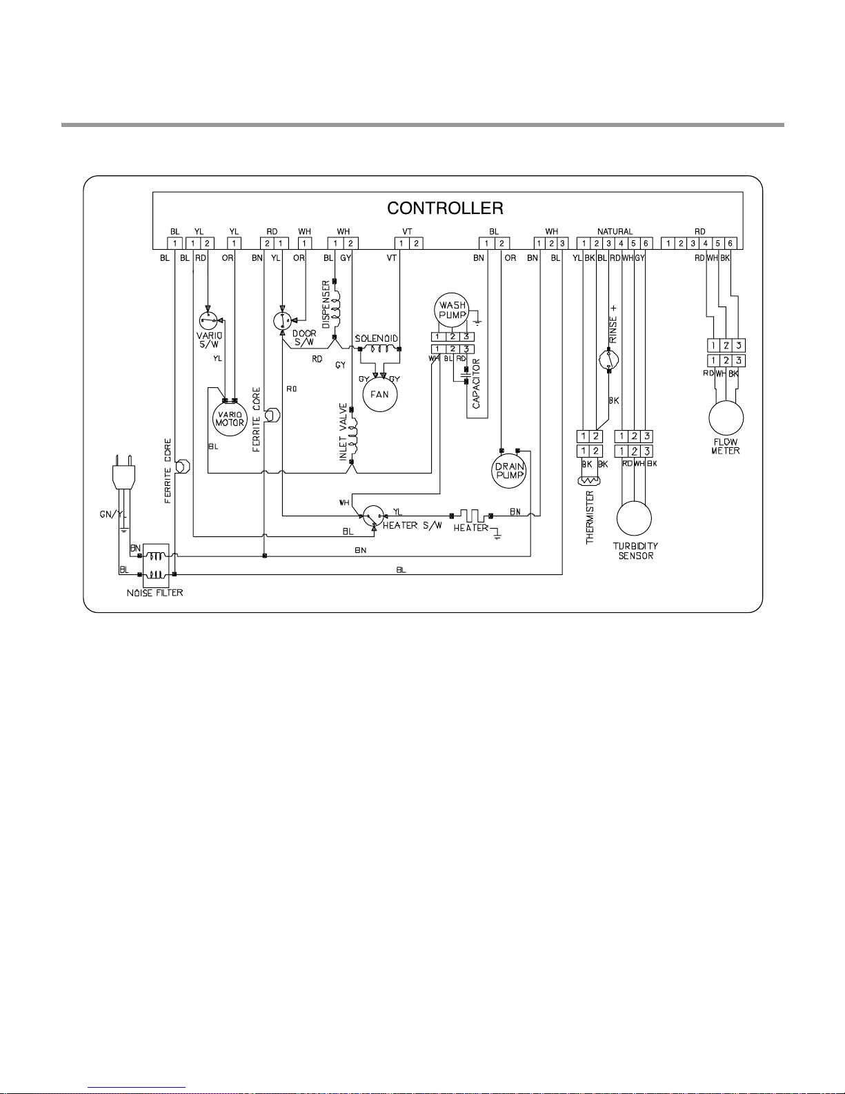
5. WIRING DIAGRAM
LD-4050W
- 13 -

5. WIRING DIAGRAM
LD-14AW2
LD-14AT2
- 14 -
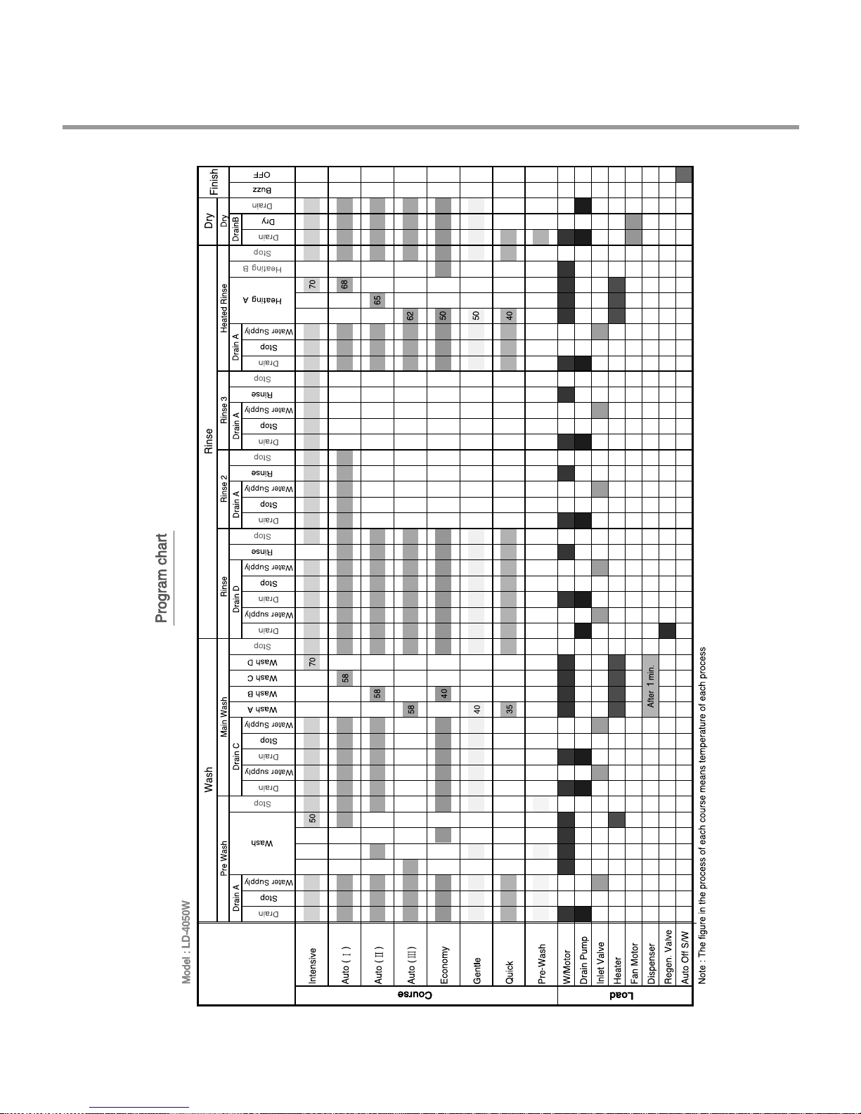
6. PROGRAM CHART(SCHEMATIC DIAGRAM)
- 15 -
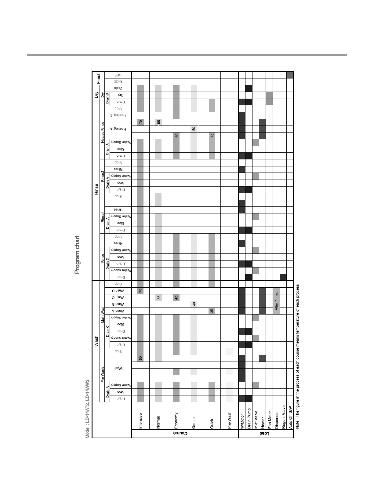
6. PROGRAM CHART
(PGM TIME Flow-Default, Vario)
- 16 -
7. HOW TO DISASSEMBLE
BEFORE DISASSEMBLING THE DISHWASHER ;
1) Remove the plug from electric outlet to avoid electric shock.
2) Close the Water Tap(faucet).
3) Remove all dishes and items in the dishwasher.
4) Remove the Lower Rack and the Upper Rack.
5) If necessary, remove the inlet hose and drain hose to avoid the hose damages.
6) Prepare some towels to avoid floor wet by the water left in the dishwasher.
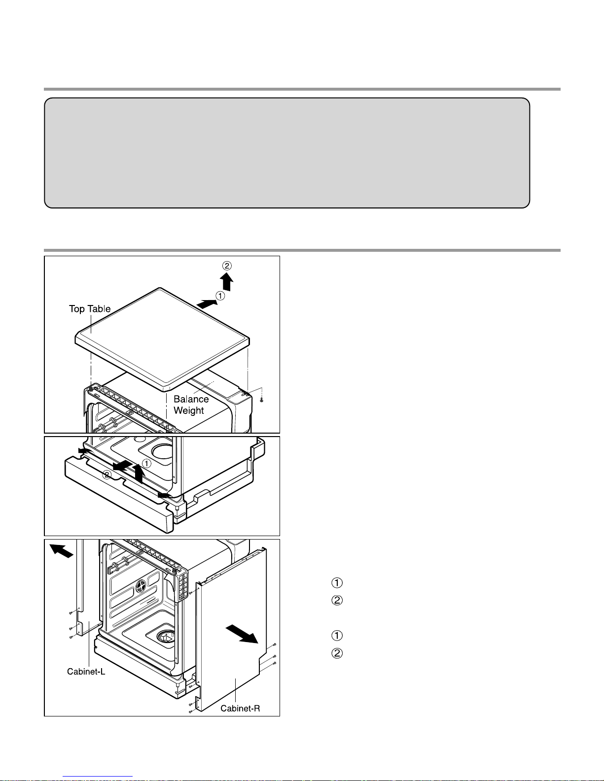
7-1. FULL DISASSEMBLE
1. Top Table
1) Remove the rear 2 screws.
2) Pull and lift the top table.
2. Low Cover
3. Cabinet-R/L
1) Cabinet-R
Remove front 4 screws.
Remove rear 3 screws.
2) Cabinet-L
Remove front 4 screws.
Remove rear 3 screws.
- 17 -
 Loading...