

LG RCWW, LCWW Maintenance Manual
www.lge.com
OPERATION & MAINTENANCE MANUAL
Water-Cooled SCREW Chiller
Model : RCWW, LCWW
Please read this installation manual completely for safety before installing the product.
The purpose of this manual is to keep the user safe and to prevent any property damage.
After reading this installation manual, please retain it for future reference thoroughly
Installation work must be performed in accordance with this installation manual by
authorized personnel only.
ENGLISH

2
ENGLISH
For your records
Staple your receipt to this page in case you need it to prove the date of purchase or for warranty
purposes. Write the model number and the serial number here:
Model number :
Serial number :
You can find them on a label on the side of each unit.
Dealer’s name :
Date of purchase :

1. CAUTIONS FOR SAFETY _ WARNING/CAUTION
3
1. CAUTIONS FOR SAFETY _ WARNING/CAUTION
It can be dangerous when moving, installing and placing the system for its high pressure, electric
devices and heavy weight especially when lifting the unit in a limited space(rooftop, lifted structure, etc.).
Please read carefully the warnings and cautions on this manual and the labels attached on the
unit, and follow the instructions.
Please follow the following instructions to prevent any injury or property damage
It may result in an injury or damages when neglecting the instructions on in this manual.
The seriousness of the result can be classified as the following signs.
• Please note that any failure of system resulted by user’s careless maintenance, natural disaster
or the failure of the power cable shall not be warranted regardless of the warranty period.
• Please note that any part of this manual can be revised without notice for the product improvement.
WARNING
It can result in serious injury or death when the directions are ignored.
CAUTION
It can result in minor injury or product damage when the directions are ignored.
This is the symbol to call attention for the issues and operations that may cause danger.
To prevent the occurrence of the danger, read carefully and follow the instructions.
This is the symbol showing the how-to-use instruction in order to prevent danger.
1-1. Warning
• Have all electric work done by a licensed electrician according to "Electric Facility Engineering Standard" and "Interior
Wire Regulations" and the instructions given in this manual and always use a special circuit.
-
If the power source capacity is inadequate or electric work is performed improperly, electric shock or fire may result.
• Ask the dealer or an authorized technician to install the chiller unit.
- Improper installation by the user may result in water leakage, electric shock, or fire.
• For re-installation of the installed product, always contact a dealer or an Authorized Service Center.
- There is risk of fire, electric shock, explosion, or injury.
• Make sure to equip the circuit breaker and fuse.
- Improper wiring or installation may cause fire or electric shock.
• Do not disassemble, repair or reconfigure the unit.
- LG Electronics is not responsible for the any damage or loss from the arbitrary disassembly, repair or reconfigura-
tion of the unit.
• Make sure to ground the unit properly.
- There is risk of fire or electric shock.
• Do not store or use flammable gas or combustibles near the chiller unit
- There is risk of fire or failure of product.
• Do not reconstruct to change the settings of the protection devices.
- If the pressure switch, thermal switch, or other protection device is shorted and operated forcibly, or parts other
than those specified by LGE are used, fire or explosion may result.
• Install the unit on a foundation where the heavy weight can be supported.
- Insufficient strength of the foundation to support the chiller operation may cause the unit failure or injury.
• Installing the product in small space requires separate measures to keep the leakage of the refrigerant within the
safety limits in case of any leakage.
- Consult the authorized dealer for appropriate measures to prevent the refrigerant leakage from exceeding the
safety limits. The leakage of refrigerant exceeding the safety limit may result in dangerous situations due to the
lack of oxygen level in the room.
!
!
!
ENGLISH

4
1. CAUTIONS FOR SAFETY _ WARNING/CAUTION
ENGLISH
• Securely install the cover of control box and the panel.
-
If the cover and panel are not installed securely, dust or water may enter the unit and fire or electric shock may result.
• Do not operate the unit arbitrarily.
- Incorrect operation of the unit may cause dangerous situations such as unit defects, leakage or electric shock. Always consult the authorized dealer.
• Do not use damaged circuit breaker or fuse works correctly all the time.
- It may cause fire, electric shock or injury.
• Keep the control panel from any water getting in. Do not wash the control panel with water.
- It can cause electric shock or defects.
• When the product is soaked (flooded or submerged), contact an Authorized Service Center.
- There is risk of fire or electric shock.
• Use a dedicated outlet for this unit.
- There is risk of fire or electric shock.
• When installing and moving the chiller unit to another site, do not charge it with a different refrigerant from the refrigerant specified on the unit.
- If a different refrigerant or air is mixed with the original refrigerant, the refrigerant cycle may malfunction and the
unit may be damaged.
• Do not touch the power switch with wet hands.
- There is risk of fire, electric shock, explosion, or injury.
• Ventilate before operating the chiller unit when gas leaked out.
- Do not use a phone or operate the power switch at this time. It may cause fire or explosion.
• Do not put any heavy object on the top of the unit or climb on the unit.
- It may cause defects or injury.
• Be careful with the rotating part.
- Do not put your finger or a stick in the rotating part. It may cause injury.
• Use fuse and leakage breaker of rated capacity.
- It may cause fire and defects.
• Redesigning the control box is prohibited.
- Lock the control box with possible locking device and if you need to open the control box inevitably, turn off the
main power first.
• Do not touch the wiring or a parts inside the panel.
- It may cause electric shock, fire or defects.
PRECAUTIONS BEFORE INSTALLATION
• Follow the permitted pressure level
- Follow the regulated pressure for cold water, cooling water, refrigerant etc.
• Do not change the set values.
- Do not change the set values of the controller and safety devices. Operating with inappropriate setting can cause
damages. When changing the setting values, please consult with the specialist.
• Be careful of fire, earthquake and lightening.
- In case of any natural disaster such as fire, earthquake or lightening, immediately stop operating the unit. If you
continue to operate the unit, it can cause a fire or electronic shock.
• Follow all safety code.
- When operate the chiller, follow the precautions on the manual, tag, sticker and label.
• Use of undesignated refrigerant and oil is prohibited.
- Do not use undesignated refrigerant, freezer oil and brine. It may cause serious effect to the compressor and
parts defect.
• During the installation and service, shut down the power supply.
- Electric shock can cause injury and death. Mark and check all switches so that the power is not recovered until
the work is completed.
• Wear safety equipment
- Wear safety glasses and work gloves. Be careful when installing or operating the chiller and operating the electrical components.
• Always run fluid through heat exchangers when adding or removing refrigerant charge.
-
Potential damage of the tube within the heat exchanger can be prevented. Use Appropriate brine solution in cooler fluid
loops to prevent the freezing of heat exchangers when equipment is exposed to temperature below 0°C.

1. CAUTIONS FOR SAFETY _ WARNING/CAUTION
5
• Do not vent refrigerant relief valves within a building.
-
Outlet from relief valves must be vented outdoors in accordance with the latest edition of ANSI/ASHRAE(American National Standards Institute/American Society of Heating, Refrigeration and Air Conditioning Engineers) 15 (Safety Code for
Mechanical Refrigeration). The accumulation of refrigerant in an enclosed space can displace oxygen and cause asphyxiation. Provide adequate ventilation in enclosed or low overhead areas. Inhalation of high concentrations of refrigerant
gas is harmful and may cause heart irregularities, unconsciousness or death. Misuse can be critical. Refrigerant gas is
heavier than air and reduces the level of oxygen. It can cause irritation to eyes and skin.
• Be careful of water leakage.
- In case of any water leakage in the pump or pipe, immediately stop operating the unit. It may cause electric
shock, electricity leakage or defects.
• Be careful of electric shock.
- Always ground the chiller during installation. It may cause electric shock.
• Do not leave refrigerant system open to air any longer than necessary.
- If the repair cannot be completed, seal the circuits to prevent any contamination or rust within the product, and
charge dry nitrogen.
• Do not reuse compressor oil.
- It can damage the product.
• During installation, make the specified grounding before supplying the power, and during the dismantling, remove
the grounding line at the end of the task.
• Use appropriate meters for measurement. Otherwise, it may cause injury or electric shock.
• Check all power connected to the control panel or starter panel to be shut off while applying the power.
- It may cause electric shock.
• Make sure to discharge the electric current before inspection or repair work.
- It may cause injury or electric shock.
• Do not open the 2nd phase side of the current transformer when power is on.
- High voltage could be discharged causing an electric shock.
• Remove foreign objects(working tools, wires, bolts, washers) after installation, inspection, and repair work.
- They may cause injury, fire, or damage.
• When using a condenser, make sure to verify the complete discharge before applying the power again. (Re-powering within 5 min. is prohibited.)
- It may cause electric shock, fire, damage, or malfunction.
• Change the condenser in case that the expansion exceeds the recommended limit.
It may cause electric shock, fire, damage, or malfunction.
1-2. Caution
Operation & Maintenance
• Always check for gas(refrigerant) leakage after installation or repair of product.
- Low refrigerant levels may cause failure of product.
• Do not install the unit where combustible gas may leak.
- There is risk of fire or failure of product
• Keep level even when installing the product.
- Unleveled refrigerant can cause problems to the product.
•
Do not use the product for special usage or location such as preserving animal/plant, precision machine, artifact, etc.
- It may cause property damage.
• Use exclusive wire for the product. Use power cables of sufficient current carring capacity and rating.
- It may cause fire and electric shock.
•
When installing the unit in a hospital, communication station, or similar place, provide sufficient protection against noise.
- The inverter equipment, private power generator, high-frquency medical equipment, or radio communication
equipment may cause the chiller to operate erroreously, or fail to operate. On the other hand, the chiller may affect such equipment by creating noise that disturbs medical treatment or image broadcasting.
• To protect the product from corrosion, do not install the product where it is exposed to sea wind(salt spray) directly.
If necessary, please install shield.
- It may cause product deformation and defects.
• Make the connections securely so that the outside force of the cable may not be applied to the termianls.
- Inadequate connetion and fastening may generate heat and cause fire. If the power cable got damaged, do not directly replace it, but call the service center for replacement first.
• Do not use the product in special environments.
- Oil, steam and sulfuric steam can deteriorate the product performance or cause damage to the parts.
• Be careful when transporting the product.
- When carrying the chiller, always consult with the specialized expert. When transporting the chiller, always follow
the methods described in the manual. If not, it can cause overturn, fall etc.
ENGLISH

6
1. CAUTIONS FOR SAFETY _ WARNING/CAUTION
• Be sure the installation area does not deteriorate with age
- If the base collapses, the chiller could fall with it, causing property damage, product failure, or personal injury.
• Be sure to dispose the packing materials safely.
- Packing materials, such as nails and other metal or wooden parts, may cause stabs or other injuries. Tear apart
and throw away plastic packing bags so that children may not play with them. If children play with a plastic bag
which was not torn apart, they face the risk of suffocation.
• Do not touch any of the refrigerant piping during and after operation.
- Pipe during and after the operation can be hot or cold depending on the condition of the refrigerant flowing
through the refrigerant pipe, compressor and refrigerant cycle parts. Touching the pipes at this time can cause
burns or frostbites.
• Turn on the main power 12 hours before starting to operate the product.
- If you operate the product immediately after turning on the main power, it can severely damage the internal parts.
Keep the main power on while operating.
• Do not immediately turn off the main power after the product stops operating.
- Wait at least 5 minutes before turning off the main power. If not, it may cause water leakage or other problems.
• Do not operate the product with the panel or safety devices removed.
- Rotating parts or high temperature/pressure parts can cause safety accidents.
• Be careful when disposing the product.
- When disposing the chiller, request to the specialized expert.
• Use a firm stool or ladder when cleaning or maintaining the chiller.
- It may cause an injury.
• Be careful of high temperature.
- Be careful not to make body contact to the parts of the chiller in high temperature. It may cause a burn.
• Be careful of high voltage.
- Install separate wiring for the power and always install and use dedicated power supply and circuit breaker. It can
cause electric shock and fire.
• Be careful of chiller installation.
- Keep enough clearance around the product for service and especially for air cooling type, install the product at well
ventilated location where there is no obstacle.
• Harsh chemical, household bleach or acid cleaner should not used to clean outdoor or indoor coils of any kind.
- These cleaners can be very difficult to rinse out of the coil and can accelerate corrosion at the fin/tube interface
where dissimilar materials are in contact. Use environment friendly cleaner.
• Be careful when restarting the product.
- When a safety device is triggered, remove the cause and then restart the product. Repeating the operation arbi-
trarily can cause fire and defect.
• Use appropriate tools.
- Use tools appropriate for the repair work and calibrate the measuring devices accurately before using. Using inap-
propriate tools can cause an accident.
• Be careful of sound and odor.
- If you hear a weird sound or smell an odor, immediately stop operating the system and contact the service center.
It may cause fire, explosion or injury.
• Be careful of injury.
- Check the safety label of the safety device. Follow the above precautions and the contents in the label. It may
cause fire and injury. To prevent the formation of the condensed water, the pipe connected to the evaporator as
well as the evaporator itself should be well insulated.
• Check.
- Perform periodic checks. If any problem occurs, stop the operation and contact the service center. Insufficient
check may cause fire, explosion or error.
• Do not attempt to bypass or alter any of the factory wiring.
- Any compressor operation in the reverse direction will result in a compressor failure that will require compressor
replacement.
• Do not use jumpers or other tools to short out components, or bypass the parts differently from recommended procedures.
-
Short-circuiting the control board ground line with other wires can damage the electric module or electric components.
• Water must be within design flow limits, and should be treated cleanly.
- This make it possible to ensure proper machine performance and reduce the potential of tubing damage due to
corrosion, scaling, erosion and algae. LG Electronics is not responsible for any damage caused by cooling water
not treated or improperly treated.
• Consult a water treatment specialist for proper treatment procedures.
- Hard scale may require chemical treatment for its prevention or remove.
ENGLISH

1. CAUTIONS FOR SAFETY _ WARNING/CAUTION
7
ENGLISH
• Do not overcharge refrigerant to the system.
- Refrigerant overcharging results in higher discharge pressure with higher cooling fluid consumption. Also it can
damage the compressor and increase the power consumption. Also it can damage the compressor and increase
the power consumption.
• Do not add different type of oil.
- It may cause abnormal operation of chiller.
• Turn controller power off before service work.
- It secures safety and prevents damage to the controller.
• Maintain the compressor oil pressure to normal level.
- Use proper safety precautions whem relieving pressure.
• Welding the evaporator head or nozzle part is not recommended.
- If the part requires welding, remove the chilled water flow switch and entering/leaving fluid thermistors before
welding. After the welding is completed, reinstall the flow switch and thermistors. Failure to remove these devices may cause component damage.
• Do not open the circuit breaker arbitrarily during the operation.
- It may cause damage or malfunction.
• Do not operate with wet hand.
- It may cause electric shock.
• During maintenance work, check whether all of the power lines connected to the control panel or starter panel are
interrupted.
- It may cause electric shock.
• When power is on, do not open the door of control panel or starter panel, and protective cover.
- It may cause electric shock.
• Do not open the circuit breaker without permission while running.
- It may cause damage or malfunction.
• Tighten bolts and screws with the specified torque.
- Otherwise, it may cause fire, damage, or malfunction.
• Do not change electric or control devices arbitrarily.
- It may cause fire, damage, or malfunction.
• Only the persons who have sufficiently studied the user's manual should operate the control panel or starter panel.
- Otherwise, it may cause injury, fire, malfunction, or damage.
• Do not perform welding work near cables connected to the main unit.
- Otherwise, it may cause fire or damage.
• Connect only the input/output signal cables specified in the drawing to the control panel or starter panel.
- Otherwise, it may cause malfunction or damage.
• Use the rated electrical cables.
- If not, it may cause fire or damage.
• Use specified parts for repair.
- If not, it may cause fire or damage.
• Install the machine, control panel, and starter panel at a place where there is no combustible material.
- Otherwise, it may cause fire.
• Do not exceed the voltage supply limit described in the relevant manual.
- Otherwise, it may cause damage or malfunction.
• Connect the signal cables connected to the control devices following the circuit diagram.
- It may cause damage or malfunction.
• Do not store the product in a place where is a flooding risk or a lot of moisture.
- Otherwise, it may cause damage or malfunction.
• Do not use the indoor control panel or starter panel outside of the building.
- Otherwise, it may cause damage or malfunction.

8
TABLE OF CONTENTS
ENGLISH
Thank you for purchasing the Water Cooled Centrifugal Chiller of LG Electronics.
Installation as instructed after reading this manual will ensure the safety, convenience and long lifetime of the unit.
• Please read this manual carefully for the correct installation and proper operation of the Centrifugal Chiller unit.
• Once the installation completed, please run the commissioning and inspect according to the operating & maintenance manual.
h This manual describes safety cautions for installation, general information, carrying and installation and wiring infor-
mation of the Water Cooled Centrifugal Chiller.
3 1. CAUTIONS FOR SAFETY
_ WARNING/CAUTION
3 1-1. Warning
5 1-2. Caution
9 2. INTRODUCTION
9 2-1. General introduction
9 2-2. System structure
10 2-3. Nomenclature
10 2-4. Name plate
11 2-5. Main unit conversions
13 3. STRUCTURE OF SCREW
CHILLER
13 3-1. Chiller cycle
14 3-2. Main components of Screw chiller
22 4. CONTROL SYSTEM
22 4-1. Components of control panel and main
parts
29 4-2. Outside view of Startup panel - Stan-
dard Type
30 4-3. Basic control algorithm
31 4-4. BMS support function
32 4-5. Control screen (Product function)
34 4-6. Screw Chiller Timing Sequence –
Run & Stop
70 4-7. Product Protection Function
70 Check points before inspection
73 5. CHECK AND TROU-
BLESHOOTING
74 5-1. Check
74 Check points before inspection
74 Check items after inspection
76 6. Commissioning
76 6-1. Delivery and Installation Check
78 6-2. Preparation for Commissioning
85 6-3. Commissioning and startup
86 6-4. Startup procedure after stopping run
for a long time
87 6-5. Stop running the product
88 7. MAINTENANCE
88 7-1. Maintenance and inspection standard
91 7-2. Periodic inspection
95 7-3. Maintenance during off-season
96 7-4. Periodical maintenance table
98 7-5. Operation Inspection Table
99 7-6. Oil maintenance
100 7-7. General maintenance
104 8. TROUBLESHOOTING
104 8-1. Causes and actions for alarms
115 8-2. Chiller problems and actions
117 8-3. Actions for screw compressor status
118 9. OPERATION RECORD
CHECK
118 9-1. Operation record check list
TABLE OF CONTENTS
2. INTRODUCTION
9
ENGLISH
2-1. General Information
This manual describes the installation of water cooled screw chiller with X30 controller applied.
2-2. System structure
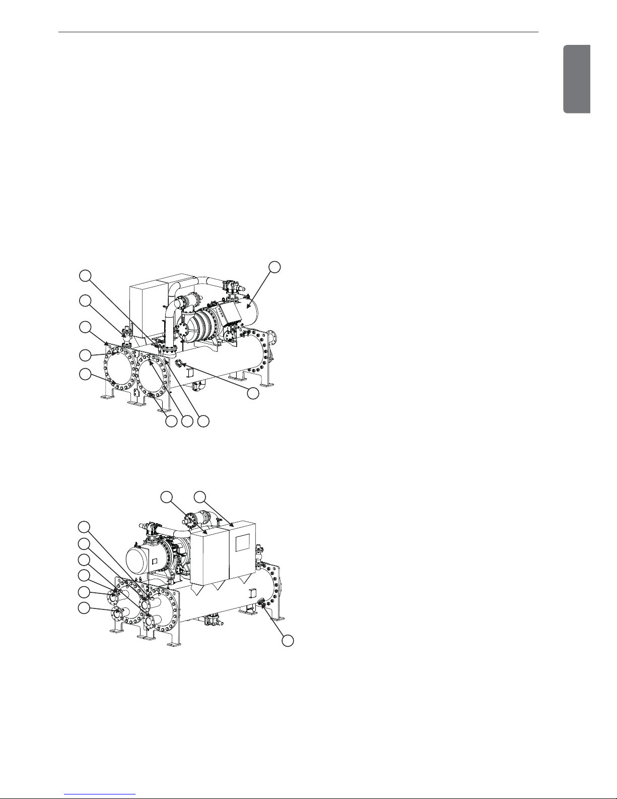
Figure 1 shows the general parts location and components of the water cooled screw chiller.
The location of control panel, type of waterbox, directions of inlet and outlet of the chilled water and cooling water
and some pipes may vary by model or customer order. Please check the approved drawings for the details.
* Prepare and check the approved drawing that fits the site.
1
2
10
4
5
6
7
8
3
9
12 11
13
15
14
16
18
17
19
Part Name
1. Screw compressor
2. Relief valve for condenser
3. Relief valve for evaporator
4. Air vent for cooling water
5. Air vent for chilled water
6. Drain for cooling water
7. Drain for chilled water
8. Lifting hole(4 holes) for condenser
9. Lifting hole(4 holes) for evaporator
10. Sight glass for evaporator
11. Control panel
12. Starter panel
13. Flow switch (Chilled water)
14. Flow switch (Cooling water)
15. Temperature sensor (Chilled water outlet)
16. Temperature sensor (Cooling water outlet)
17. Temperature sensor (Chilled water inlet)
18. Temperature sensor (Cooling water inlet)
19. Sight glass for condenser
Front view
Rear view
Figure 1 General structure of screw chiller
2. INTRODUCTION
10
2. INTRODUCTION
ENGLISH
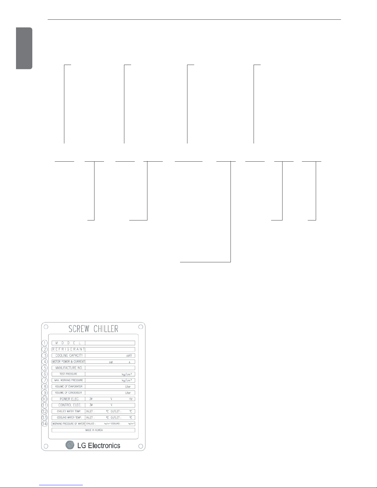
2-4. Name plate
Name plate for the unit is attached on the control panel. General information of the chiller unit can be obtained from
the plate and the information of the unit history can be used for quicker service.
Fig. 3. Product plate
① Model name
② Refrigerant
③ Cooling capacity
④ Power and current required for motor
⑤ Manufacture's serial number
⑥ Internal pressure test pressure
⑦ Maximum working pressure (Design pressure)
⑧ Volume of Evaporator
⑨ Volume of Condenser
⑩ Power electricity
⑪ Control electricity
⑫ Temperatures of Chilled water inlet/outlet
⑬ Temperatures of Cooling water inlet/outlet
⑭ Maximum pressure of chilled water and cooling water
2-3. Nomenclature
The model naming for screw chiller is done as follows.
RCWW030A A 1 1
R : R-134a
Compressor
quantity
C:Chiller
Development sequence
order
W : Screw
compressor
A : Flooded type
B : Direct expansion type
C : Falling film system
M : Ice Storage High Efficiency
R : Heat recovery
N : Nuclear PJT, High Efficiency
W : W type condenser
V : V type Condenser
S : Special
W : Water-cooled
cooling only
K : Water-cooled
heat pump
A : Air-cooled cool-
ing only
Compressor nominal
capacity in Tons(usRT)
10RT ⇨ 001
100RT ⇨ 010
130RT ⇨ 013
1000RT ⇨ 100
Cooling/chilled water maximum working pressures
A : Chilled water 10kg/cm
2
,
Cooling water 10kg/cm
2
B : Chilled water 16kg/cm2,
Cooling water 16kg/cm
2
C : Chilled water 20kg/cm2,
Cooling water 20kg/cm
2
D : Chilled water 8kg/cm2,
Cooling water 8kg/cm
2
E : ETC
Figure 2. Nomenclature
2. INTRODUCTION
11
• °F = (9/5 x °C) + 32
• °C = 5/9 x (°F - 32)
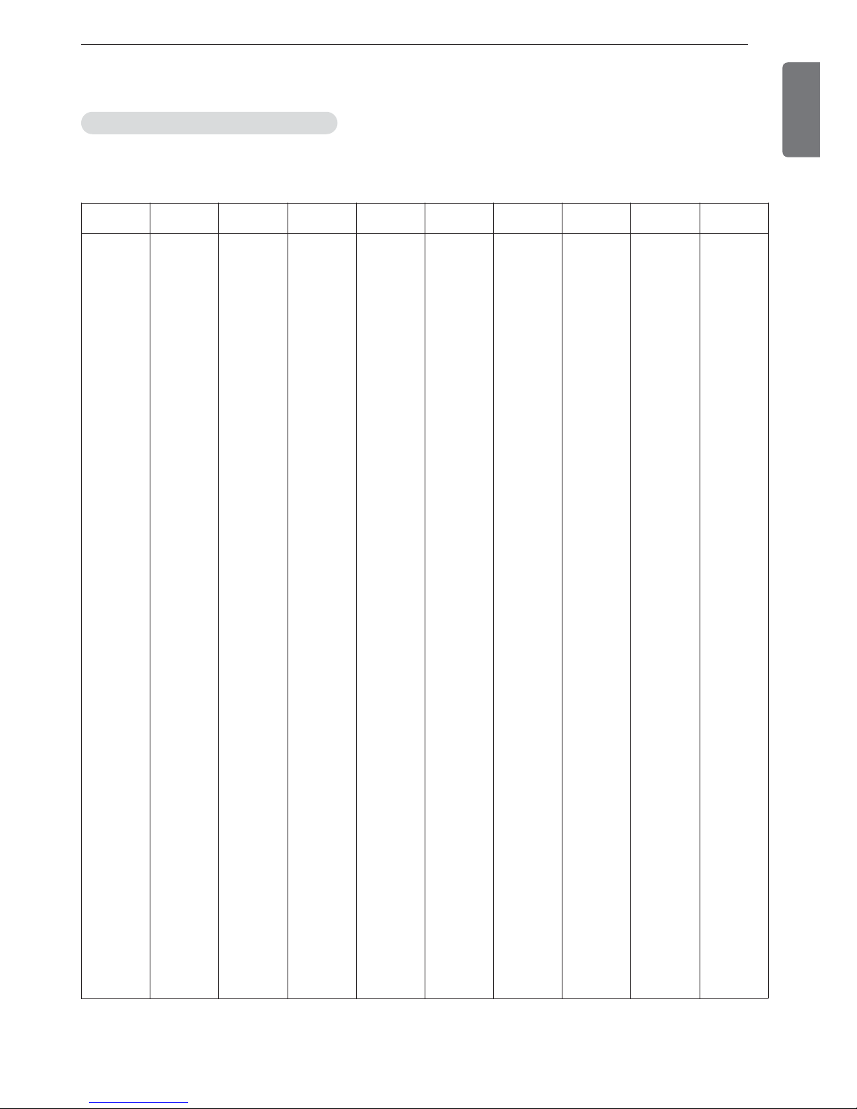
2-5. Main unit conversions
ENGLISH
°F °C °F °C °F °C °F °C °F °C
1
2
3
4
5
6
7
8
9
10
11
12
13
14
15
16
17
18
19
20
21
22
23
24
25
26
27
28
29
30
-17.2
-16.7
-16.1
-15.6
-15.0
-14.4
-13.9
-13.3
-12.8
-12.2
-11.7
-11.1
-10.6
-10.0
-9.4
-8.9
-8.3
-7.8
-7.2
-6.7
-6.1
-5.6
-5.0
-4.4
-3.9
-3.3
-2.8
-2.2
-1.7
-1.1
31
32
33
34
35
36
37
38
39
40
41
42
43
44
45
46
47
48
49
50
51
52
53
54
55
56
57
58
59
60
-0.6
0
0.6
1.1
1.7
2.2
2.8
3.3
3.9
4.4
5.0
5.6
6.1
6.7
7.2
7.8
8.3
8.9
9.4
10.0
10.6
11.1
11.7
12.2
12.8
13.3
13.9
14.4
15.0
15.6
61
62
63
64
65
66
67
68
69
70
71
72
73
74
75
76
77
78
79
80
81
82
83
84
85
86
87
88
89
90
16.1
16.7
17.2
17.8
18.3
18.9
19.4
20.0
20.6
21.1
21.7
22.2
22.8
23.3
23.9
24.4
25.0
25.6
26.1
26.7
27.2
27.8
28.3
28.9
29.4
30.0
30.6
31.1
31.7
32.2
91
92
93
94
95
96
97
98
99
100
101
102
103
104
105
106
107
108
109
110
111
112
113
114
115
116
117
118
119
120
32.8
33.3
33.9
34.4
35.0
35.6
36.1
36.7
37.2
37.9
38.3
38.9
39.4
40.0
40.6
41.1
41.7
42.2
42.8
43.3
43.9
44.4
45.0
45.6
46.1
46.7
47.2
47.8
48.3
48.9
121
122
123
124
125
126
127
128
129
130
131
132
133
134
135
136
137
138
139
140
141
142
143
144
145
146
147
148
149
150
49.4
50.0
50.6
51.1
51.7
52.2
52.8
53.3
53.9
54.4
55.0
55.6
56.1
56.7
57.2
57.8
58.3
58.9
59.4
60.0
60.6
61.1
61.7
62.2
62.8
63.3
63.9
64.4
65.0
65.6
Table 1 Temperature conversion table
Temperature conversion table (°F ↔ °C)
12
2. INTRODUCTION
ENGLISH
• lb/in2= psi
ex) 1 lb/in2 = 0.07030696 kg/cm
2
lb/in
2
kg/cm
2
lb/in
2
kg/cm
2
lb/in
2
kg/cm
2
lb/in
2
kg/cm
2
lb/in
2
kg/cm
2
1
2
3
4
5
6
7
8
9
10
11
12
13
14
15
16
17
18
19
20
21
22
23
24
25
26
27
28
29
30
31
32
33
34
35
36
37
38
39
40
0.070
0.141
0.211
0.281
0.352
0.422
0.492
0.563
0.633
0.703
0.773
0.844
0.914
0.984
1.055
1.125
1.195
1.266
1.336
1.406
1.477
1.547
1.617
1.687
1.758
1.828
1.898
1.969
2.039
2.109
2.180
2.250
2.320
2.390
2.461
2.531
2.601
2.672
2.742
2.812
41
42
43
44
45
46
47
48
49
50
51
52
53
54
55
56
57
58
59
60
61
62
63
64
65
66
67
68
69
70
71
72
73
74
75
76
77
78
79
80
2.883
2.953
3.023
3.094
3.164
3.234
3.304
3.375
3.445
3.515
3.586
3.646
3.726
3.797
3.867
3.987
4.008
4.078
4.148
4.218
4.289
4.359
4.429
4.500
4.570
4.640
4.711
4.781
4.851
4.921
4.992
5.062
5.132
5.203
5.273
5.343
5.414
5.484
5.554
5.625
81
82
83
84
85
86
87
88
89
90
91
92
93
94
95
96
97
98
99
100
101
102
103
104
105
106
107
108
109
110
111
112
113
114
115
116
117
118
119
120
5.695
5.765
5.836
5.906
5.976
6.046
6.117
6.187
6.257
6.328
6.398
6.468
6.539
6.609
6.679
6.750
6.820
6.890
6.968
7.031
7.101
7.171
7.242
7.312
7.382
7.453
7.523
7.593
7.663
7.734
7.804
7.874
7.945
8.015
8.085
8.156
8.226
8.296
8.367
8.437
121
122
123
124
125
126
127
128
129
130
131
132
133
134
135
136
137
138
139
140
141
142
143
144
145
146
147
148
149
150
151
152
153
154
155
156
157
158
159
160
8.507
8.577
8.648
8.718
8.788
8.859
8.929
8.999
9.070
9.140
9.210
9.281
9.351
9.421
9.491
9.562
9.632
9.702
9.773
9.843
9.913
9.984
10.05
10.12
10.19
10.26
10.34
10.41
10.48
10.55
10.62
10.69
10.76
10.83
10.90
10.97
11.04
11.11
11.18
11.25
161
162
163
164
165
166
167
168
169
170
171
172
173
174
175
176
177
178
179
180
181
182
183
184
185
186
187
188
189
190
191
192
193
194
195
196
197
198
199
200
11.32
11.39
11.46
11.53
11.60
11.67
11.74
11.81
11.88
11.95
12.02
12.09
12.16
12.23
12.30
12.37
12.44
12.51
12.58
12.66
12.73
12.80
12.87
12.94
13.01
13.08
13.15
13.22
13.29
13.36
13.43
13.50
13.57
13.64
13.71
13.78
13.85
13.92
13.99
14.06
Table 2. Pressure conversion table
Pressure conversion table (lb/in2↔ kg/cm2)
3. STRUCTURE OF SCREW CHILLER
13
3. STRUCTURE OF SCREW CHILLER
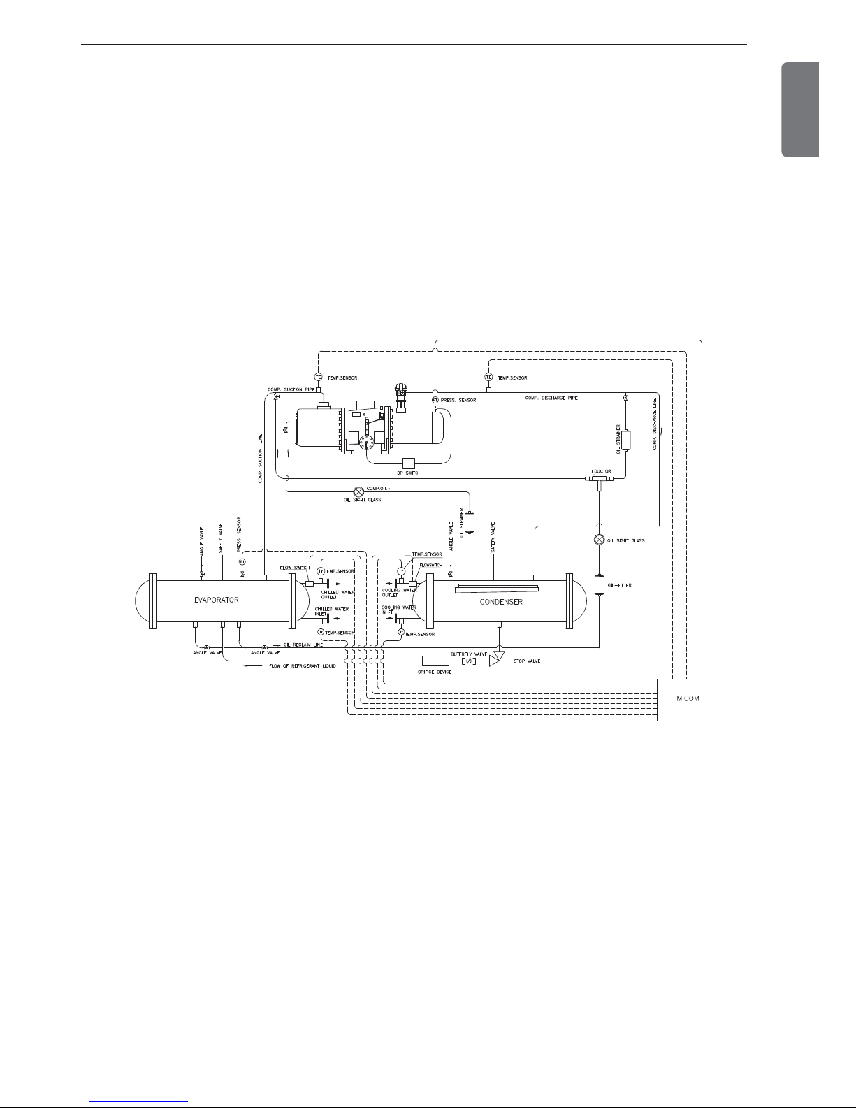
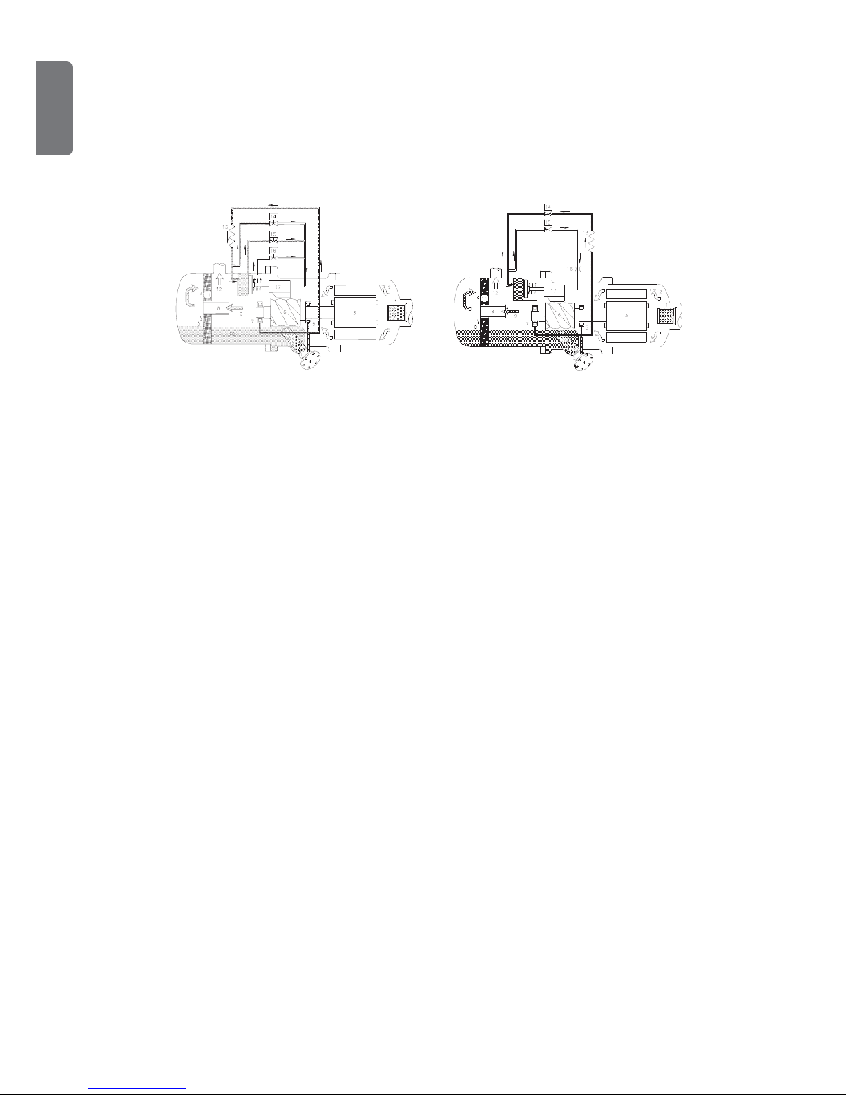
3-1. Chiller cycle
As shown in the chiller cycle figure below, the compressor discharges the high temperature/pressure refrigerant to
the condenser through the exhaust outlet in gas state. The refrigerant in the gas state in the condenser flows outside of the tube, while the cooling water flows inside of the tube. The refrigerant in high temperature and pressure
is condensed as the heat is taken away by the cooling water inside the heat pipe of the condenser. The condensed
refrigerant is gathered in the bottom of the condenser and goes through the dryer filter, orifice or expansion valve
by differential pressure, and into the evaporator. The chilled water is finally obtained in the chiller’s evaporator. During the gasification stage, the refrigerant in liquid state absorbs a large amount of heat from the cooling water and is
converted into gas state. And during the cooling water is getting colder, the refrigerant in gas state is absorbed into
the compressor. There, the gas state refrigerant is compressed by the compressor into high temp/high pressure refrigerant and sent again to the condenser. And the same cycle begins again.
ENGLISH
Figure 4 Chiller cycle(1 cycle)
14
3. STRUCTURE OF SCREW CHILLER
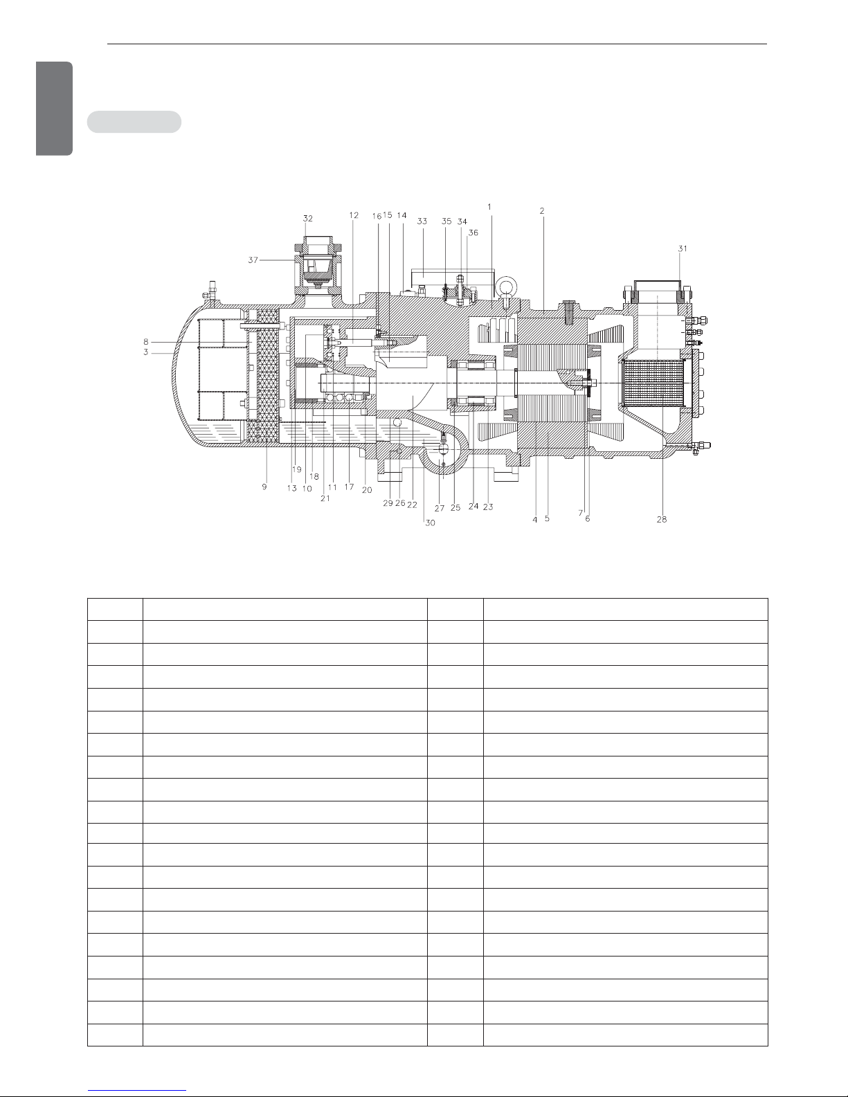
3-2. Main components of Screw chiller
ENGLISH
Compressor
Item Description Item Description
1 Compressor casing 20 α-Balance piston
2 Motor casing 21 Bearing lock nut
3 Oil separator 22 Male rotor
4 Motor rotor 23 Suction side bearings
5 Motor stator 24 Suction side bearings spacer ring
6 Motor rotor washer 25 Oil guide ring
7 Motor rotor spacer ring 26 Oil level sight glass
8 Oil separator baffle 27 Oil filler cartridge
9 Oil separator cartridge 28 Suction filter
10 Piston 29 Oil heater
11 Piston spring 30 Refrigeration lubricant
12 Piston rod 31 Suction flange
13 Bearing seat’s cover plate 32 Discharge flange
14 Solenoid valve 33 Cable box
15 Slide valve 34 Power connection bolt
16 Slide valve key 35 Thermostat terminals
17 Discharge bearings 36 Motor cable cover plate
18 Discharge fixed ring 37 Discharge check valve
19 Disc spring
Figure 5 Screw compressor
In this machine, semi-hermetic twin screw compressor, which was developed especially for air conditioning use, is
installed. The structure of the compressor is shown in the picture below.
3. STRUCTURE OF SCREW CHILLER
15
ENGLISH
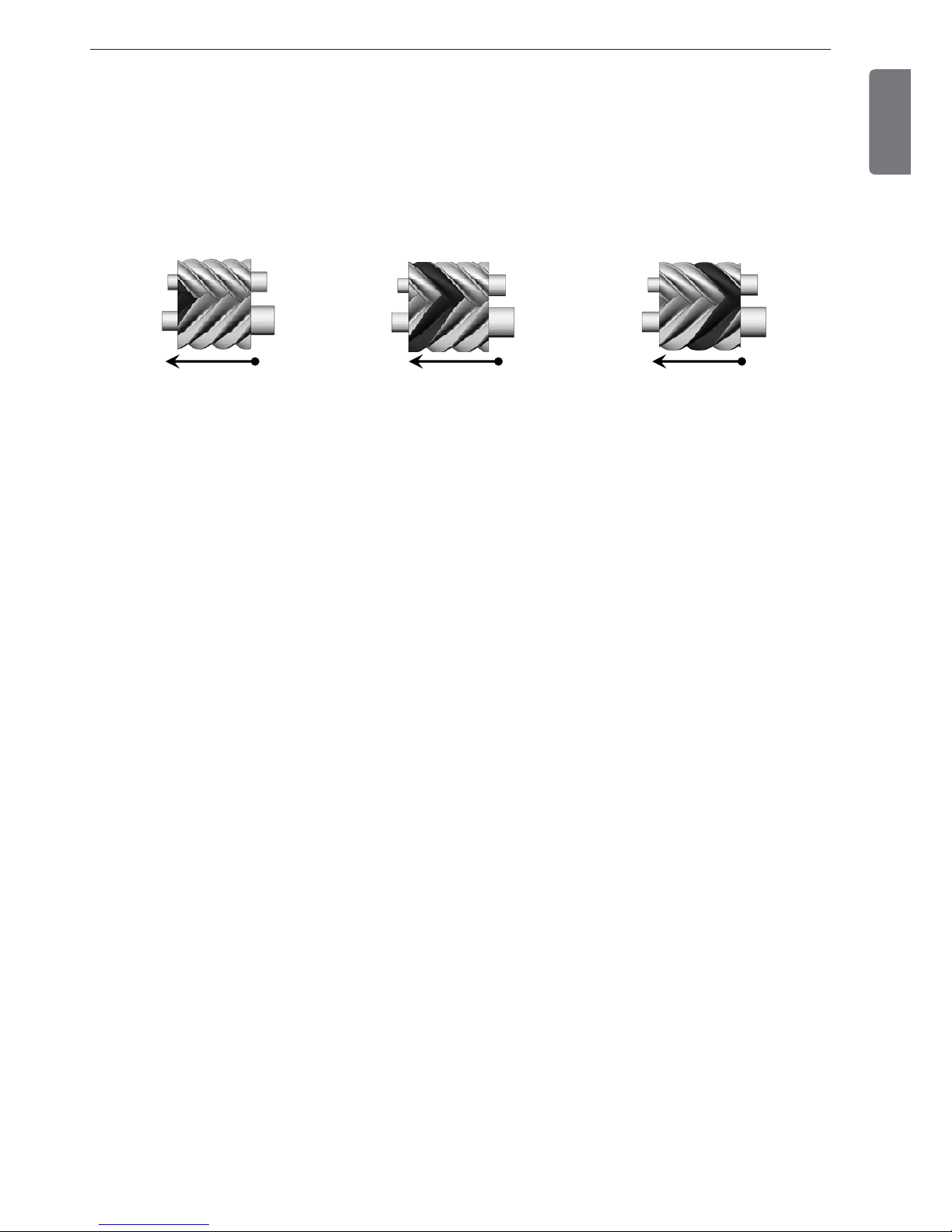
- Compression process
- Capacity control system
As shown in Figure 6 below, during the rotation of the rotors, the absorbed gas is pushed to the discharge side. In other
words, the V-shaped space formed between the male and female rotors is continuously moving to the discharge side.
The gas sealed in the lobe space which is reduced by the discharge side is compressed, and the highly compressed gas at
the end part is discharged to the oil separator. The size and geometry of the outlet port determine the so-called “internal
volume ratio (Vi)” of the compressor. In actual operation, if the compression ratio is either bigger or smaller than this value,
the efficiency will be lowered.
The screw series compressors are equipped with either 3-step/4-step capacity control system or continuous capacity
control system.
The capacity control system consists of slide valve, piston rod, cylinder, piston and piston rings while slide valve and
the piston are connected by the piston rod. The principle of operation is using the oil pressure to drive the piston in
the cylinder as shown in Figure 6, the lubrication oil flows from the oil tank through the oil filter and capillary, then is
charged into the cylinder due to the positive oil pressure which is bigger than the opposite side of spring force plus
the high pressure of the gas.
This pressure difference causes the piston to move toward the right side in the cylinder and the slide valve to move
toward the right side, increasing the amount of compressor outlet, thereby increasing the refrigeration capacity.
Also, when a solenoid valve (in 3-step/4-step capacity control system) is opened, the high pressure oil in the cylinder
is bypassed, which causes the piston and the slide valve to move toward the left side, and some of the refrigerant
gas returns to the suction side. As a result, the discharge amount is reduced and the refrigeration capacity decreases.
When the compressor is stopped, the piston spring pushes the piston back to the original position, thereby reducing
the starting current for the next startup.
If the compressor started at full load capacity it may result in over-current start.
The capillary inhibits the oil flow and makes the piston move smoothly under stepless control or controlled by micom
or temperature switch.
If the oil filter, capillary, or solenoid valves are not working properly, the capacity control system will be operated ab-
normally and make the system useless.
(C) Discharge (B) Compression (A) Suction and sealing
Figure 6 Compression process
16
3. STRUCTURE OF SCREW CHILLER
ENGLISH
4-steps capacity control Step-less capacity control
Figure 7 Capacity control system
Since the compressor should be started at the minimum load condition, the solenoid valve (capacity reducing solenoid valve in stepless control system, or minimum load solenoid valve in the stage control capacity control system)
should be kept open for 20-30 seconds before stopping or starting the compressor so that there is no oil left inside
the cylinder when starting the compressor.
- Lubrication
The main function of the lubrication oil inside the screw compressor is sealing of the inside body, cooling and capacity control. The oil pressure inside the cylinder moves the piston and slide valve which are connected to piston rod inside the compression chamber. Since the screw compressor is designed to include the lubrication system which is
based upon the pressure difference between the high and the low pressure levels, a separate oil pump is not required inside the compressor(such as reciprocating compressor). However, for some special equipment, it is necessary to install an oil pump in the compressor additionally for the safety purpose.
The bearings used in the compressor are of a rather small size, but it needs a definite amount of lubrication oil. The
purpose of feeding oil into the compression chamber is to increase the efficiency and to form oil sealing layer in order
to absorb a part of the compression heat. In order to separate the oil from the refrigerant in which oil is mixed together, the oil separator is designed to allow the oil flow into the system to the minimum. The oil temperature which
is a very important factor to the life of the compressor bearings should be watched very closely.
High oil temperature reduces the oil viscosity and worsens the lubricity and heat absorbability inside the compressor.
It is recommended to keep the oil viscosity above 10mm
2
/s at any temperature. The oil temperature should be kept
above the system condensation temperature in summer season in order to avoid the refrigerant mixed with oil entering into the system. When the outside temperature is low, the oil viscosity rises high, and the compressor which is
of the high durability should be started, thus reducing the oil pressure inside the oil piping which is needed to load oil
into the compressor. A better solution is preheating the oil in order to reach the condensing temperature in a short
period of time.
In the compressor, at least 2 oil level gages are equipped, one is high oil level gage, the other low oil level gage.
The normal amount of oil in the compressor oil tank when the compressor is running, should be in the state that
when the oil level is maintained in the middle range between the top of the low level oil gage and the top of high oil
level gage.
3. STRUCTURE OF SCREW CHILLER
17
ENGLISH
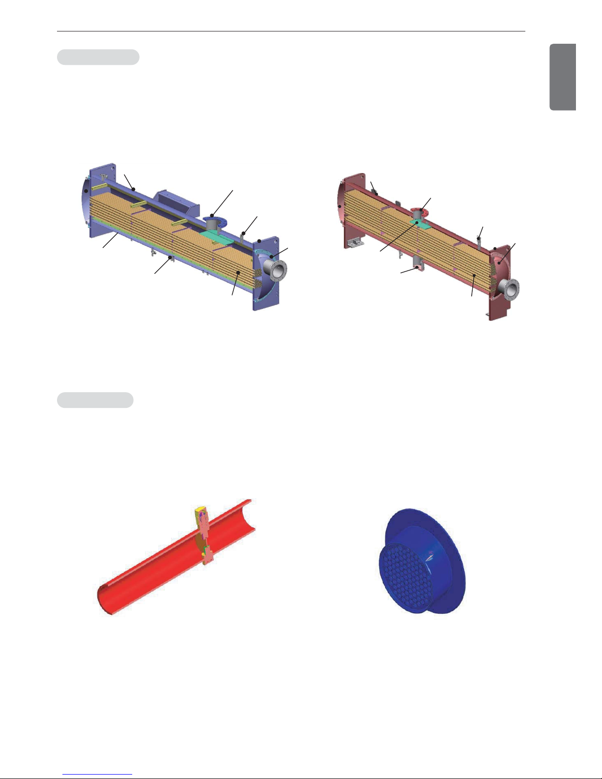
Screw chiller heat exchanger is composed of evaporator and condenser, and has 2 shells which can be conveniently
separated. To maximize the heat exchanging capability, the tube arrangement is optimized, and to prevent the decrease of COP, refrigerant distributor is installed for the even distribution of liquid refrigerant in the entire tubes. And
an efficiency increasing subsidiary cooler is installed for over-cooling of condensed liquid refrigerant.
At the upper part of the heat exchanger, relief valve is installed in cases for abnormal situations.
Heat exchanger
Expansion unit
Safety valve
Refrigerant outlet
Body
Refrigerant distributor
Refrigerant inlet
tube
Refrigerant inlet
Collision
prevention plate
Refrigerant inlet
tube
Safety valve
Inlet
Body
Inlet
Figure 8. Evaporator Figure 9. Condenser
Figure 10. Butterfly valve Figure 11. Orifice
Expansion unit consists of butterfly valve and orifice. At 100% load situation, the pressure loss at the orifice is
smaller than the refrigerant pressure loss in the condenser, thus the super-cooled refrigerant passes through the orifice. At this stage the maximum amount of refrigerant is flowing into the evaporator. As the load reduces gradually,
the circulating amount of refrigerant also reduces and accordingly the refrigerant level in the condenser is getting
low. When the amount of liquid refrigerant reduces, the gas amount in the orifice is getting larger, raising the resistance thus controlling the flow rate.
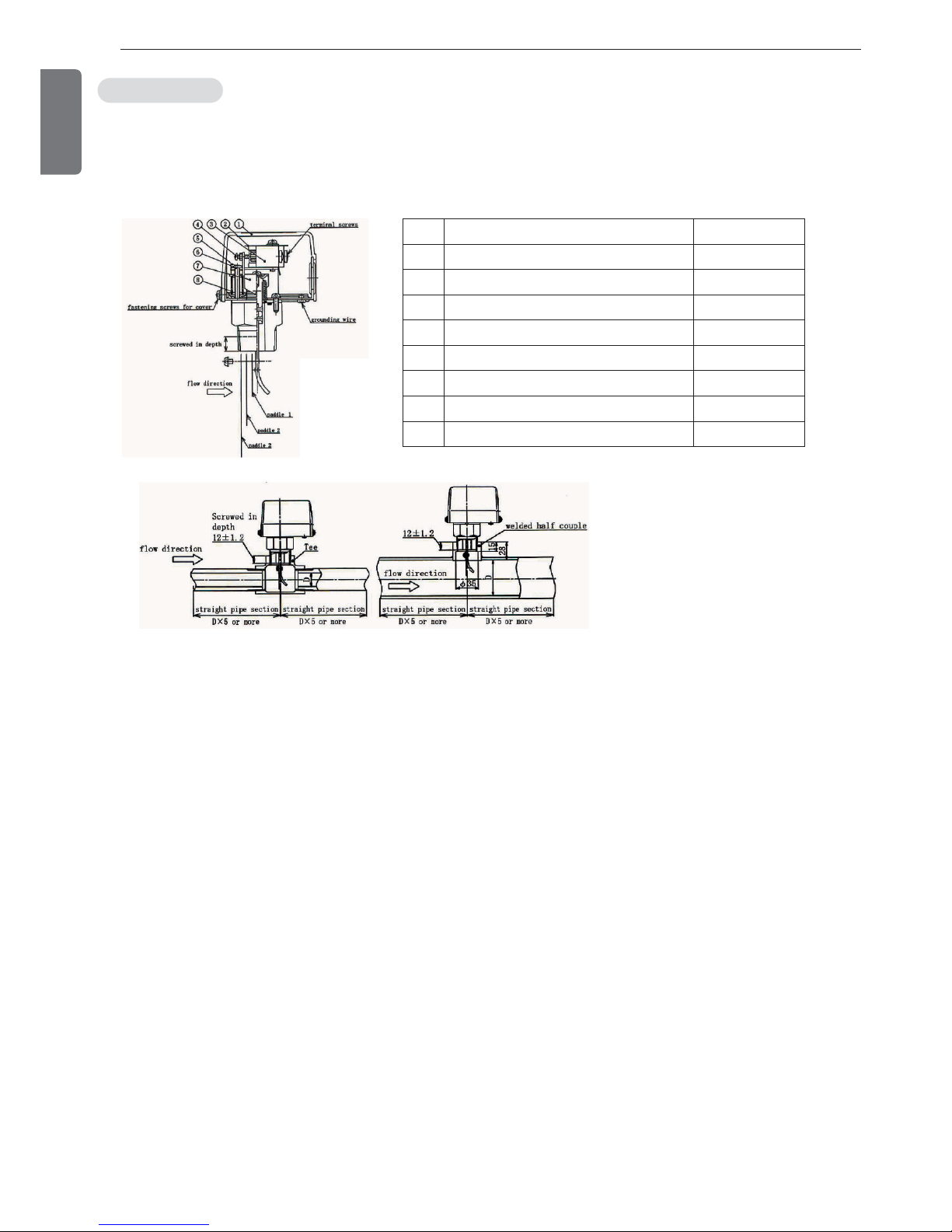
The flow switch is installed at the water outlet nozzles in all equipment as the basic setting. The following figure
shows the flow switch installed in the normal method.
Oil flow switch
Figure 12 Flow switch
18
3. STRUCTURE OF SCREW CHILLER
ENGLISH
Num-
ber
Description Quantity
1 Cover 1
2 Insulation board 1
3 Micro switch 1
4 Adjustment screw 1
5 Metal plate installation for flow control switch 1
6 Flow control screw 1
7 Operation plate 1
8 Adjustment spring 1
3. STRUCTURE OF SCREW CHILLER
19
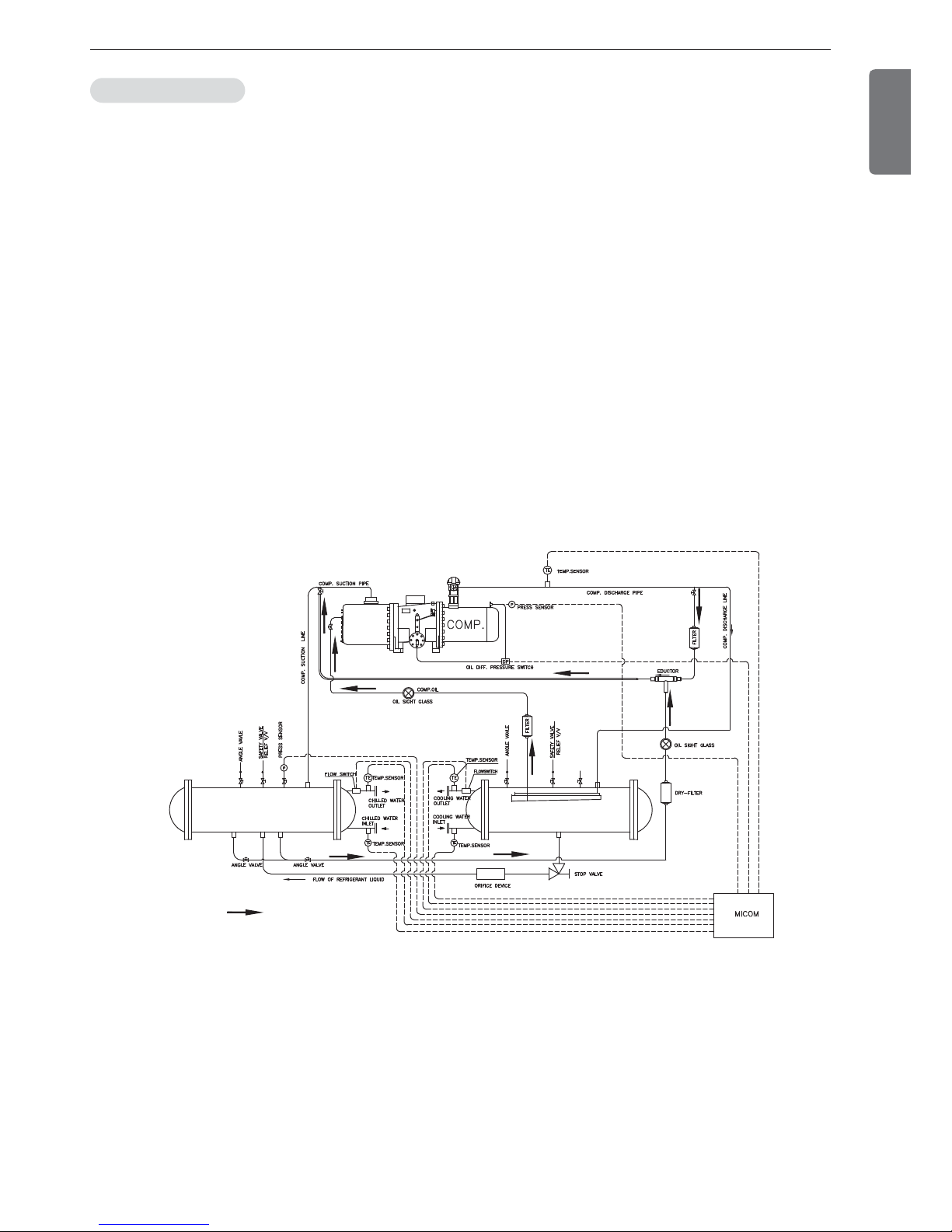
Screw compressor
Oil recovery eductor
Evaporator
Condenser
Oil line
Oil is gathered in the lower part of the compressor casing while all the oil needed for bearings and capacity control is
filtered by passing through the oil filter. After removing the foreign material the oil is sprayed to the bearings after
passing through the internal oil passage, while at the same time sprayed to the capacity control piston after passing
through the capillary in the outside. Oil flows through the capacity control solenoid valve and is discharged to the
compressor inlet side and absorbed into the rotor groove to lubricate the two rotors. The oil moved into the bearings
at the rear side returns to the inlet side.
The oil level of the compressor should be kept at a proper level during the compressor operation, and if the oil
amount is not enough, the oil should be added to the oil tank. If oil amount is insufficient, abrasion occurs at bearings
and rotor, which is the cause of the compressor damage. Oil filter which is to filter the foreign material in oil is easily
disassembled for cleaning.
Oil is filled inside of the compressor.
Depending upon the customer’s need, a different type of oil can be used, but in this case, the following items should
be followed.
- Use of a new oil should be consulted with LG Electronics first.
- The oil inside the compressor should be cleaned before filling the new oil.
- Different types of oil should not be blended together for use.
- After filling the new oil, the moisture content in the oil should be removed by a sufficient vacuum operation.
Oil recovery system
Figure 13 Oil recovery system(1 cycle)
ENGLISH
20
3. STRUCTURE OF SCREW CHILLER
ENGLISH
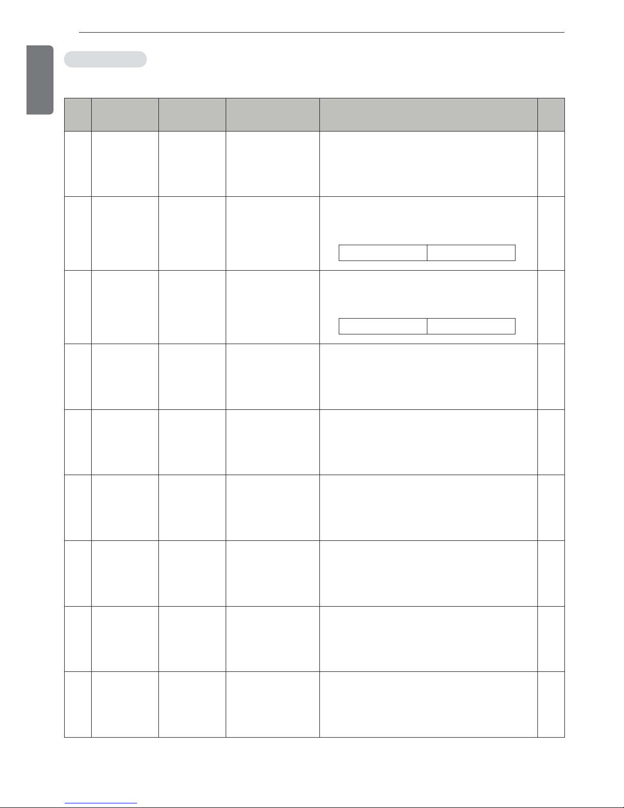
The following devices are installed for safe operation and equipment protection(1 cycle).
Safety devices
No. Item
Installed
location
Measurement
objects
Contents
Quan-
tity
1
Chilled water
low temp.
Chilled water
inlet nozzle
Chilled water inlet
temp.
This function stops the chiller when chilled water
outlet temp. becomes 2.9°C or less to avoid the
danger of freezing of chilled water.
Never change this setting.
1
2
Evaporator refrigerants low
pressure (low
temperature)
Evaporator
shell
Evaporation
pressure (temp.)
If the pressure in the evaporator becomes lower
than the value in the table below, the chiller will
stop.
1
3
Condenser
high pressure
(high tempera-
ture)
Condenser
shell
Condensing
pressure (temp.)
If the pressure in the condenser becomes higher
than the value in the table below, the chiller will
stop.
1
4
Evaporator re-
frigerant low
temperature
Evaporator
inlet
Evaporator
refrigerant temp.
When evaporator pressure is used to protect
compressor motor, and the temperature drops to
1.5 °C or below, the chiller will stop
1
5
Compressor
discharge high
temperature
Compressor
outlet
Compressor dis-
charge temp.
If compressor discharge gas temperature becomes 100 °C or higher, the chiller will stop.
1
6
Refrigerant
high/low pres-
sure difference
low
Evaporator
shell, Con-
denser shell
Pressure difference
between Evapora-
tor/Condenser
If the pressure difference is smaller than 4 bar,
the chiller will stop.
1
7
Chilled water
pump problem
Chilled water
header
Chilled water loss
head
When the chilled water flow amount passing
through evaporator tubes decreases and if water
head loss becomes less than the set value, the
chiller will stop.
1
8
Cooling water
pump problem
Cooling water
header
Over-current
When the cooling water flow amount passing
through condenser tubes decreases and water
head loss becomes less than the set value, the
chiller will stop.
1
9
Current limit
function
Control panel Motor current
Compressor motor current is measured, and according to the excess percentage over the set
current value, different ignore times are applied,
and the chiller stops accordingly .
1
Standard setting 1.90kg/cm
2
Standard setting 10.10kg/cm
2
3. STRUCTURE OF SCREW CHILLER
21
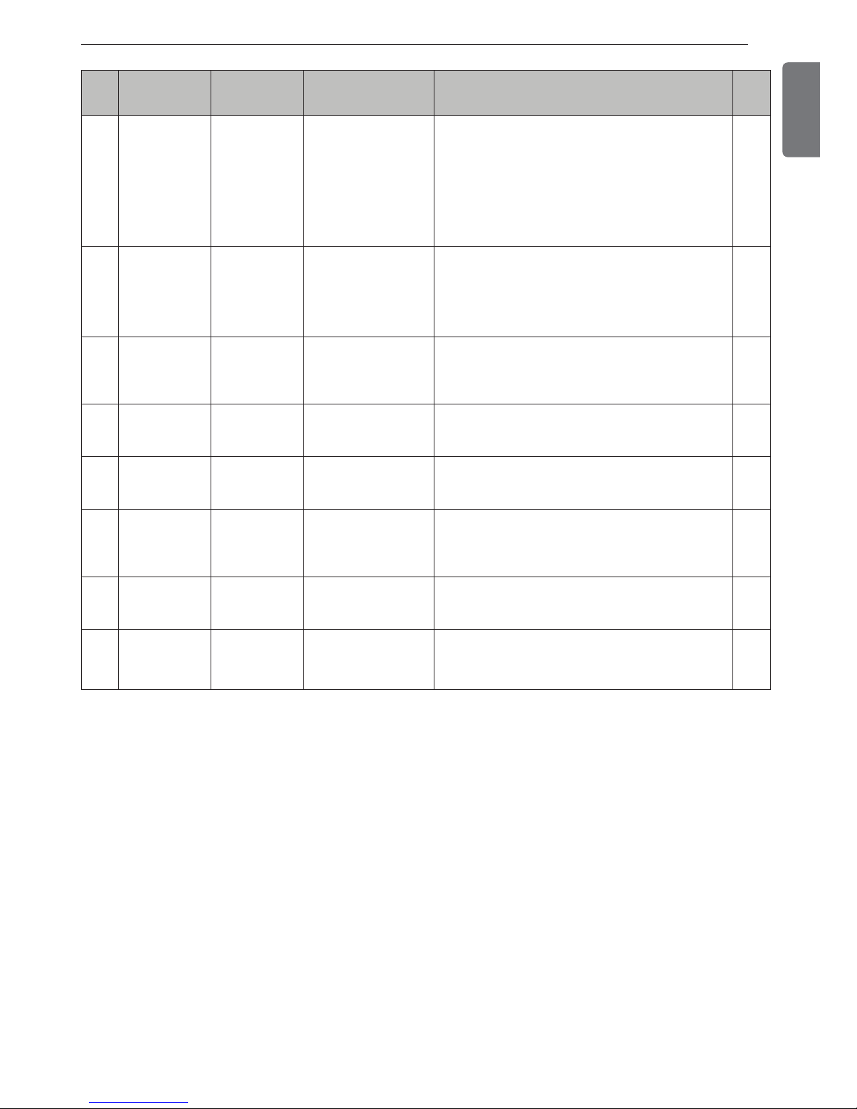
ENGLISH
No. Item
Installed
location
Measurement
objects
Contents
Quan-
tity
10
Temp. sensor
problem
5 places includ-
ing chilled
water nozzle.
Temperature sensors
It shows up when the temperature sensor is not
connected or there is a defect in the temperature
sensor.
5
11
Pressure sen-
sor problem
2 places
including
evaporator
shell
Each pressure sensor
It shows up when pressure sensor is not connected or there is a defect in the pressure sensor.
2
12 Motor status Control panel Motor status When motor has a problem, the chiller will stop. 1
13
Motor power
problem
Control panel Motor power
When there is a problem in the motor power supply, the chiller will stop.
1
14
External
problem
Control panel External fault signal
If a buyer makes a fault signal from the buyer’s
system, the chiller will stop.
1
15
Chilled
water/Cooling
water pump
interlock
Control panel
Chilled water/Cooling
water pump interlock
When chilled water/cooling water pump interlock
has a problem during running, the chiller will
stop.
2
16 Oil status Control panel Oil level When oil level is abnormal, the chiller will stop. 1
17
Refrigerant
pressure
status
Control panel Refrigerant pressure
When refrigerant pressure abnormal switch
makes signal, the chiller will stop.
1
Table 3. Safety devices
22
4. CONTROL SYSTEM
ENGLISH
4. CONTROL SYSTEM
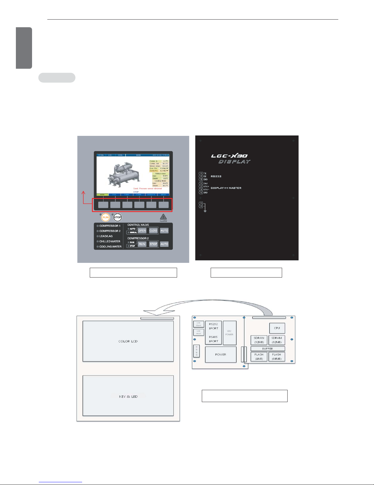
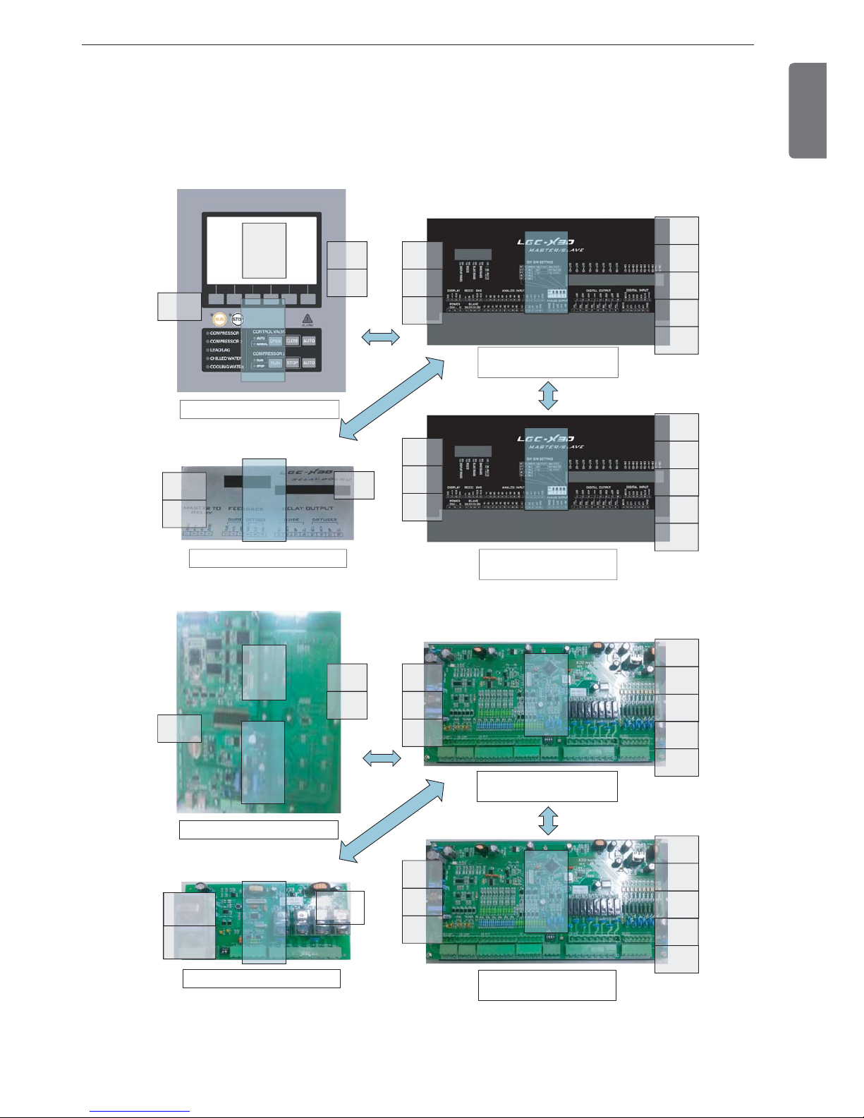
4-1. Components of control panel and main parts
HMI with 7 inch Color LCD is composed as a graphic type.
There are start/stop, control valve 2 and Compressor 2, compressor, lead/lag lamp, and chilled water / coolant flow
lamp keys.
There are ‘function keys’ at the bottom of the screen that change according to the current screen to be able to access lower categories.
Controller
Function keyFunction key
Function key
Figure 14. Controller
Front view of controller Back view of controller
Internal diagram of controller
4. CONTROL SYSTEM
23
ENGLISH
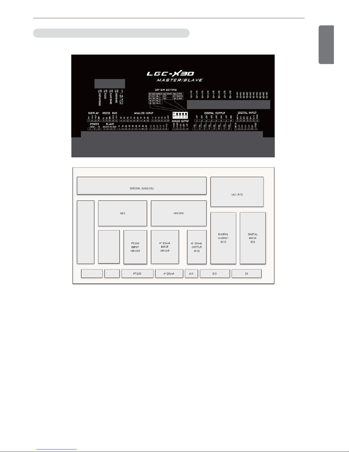
Schematic diagram of the main board(main control unit) - PCB
Figure 15 Internal diagram of Master/Slave boards
Power supply unit
POWER SUPPLY PART
POWER
FILTER
Power input
COMMUN
-ICATION
Communication
Power filter

24
4. CONTROL SYSTEM
ENGLISH
The Control unit of LG chiller controls temperature, pressure, flow rate, current, voltage, power and capacity control
valve using high capacity microprocessor. It is constructed to provide the high reliability chiller operation using LG's
unique optimum control algorithm.
Our controller unit has the following features.
1. 7 inch Color wide LCD Display (800*480 Graphic)
2. Remote operation/stop function which allows the chiller to be operated remotely.
3. Scheduled operaton function which allows setting the operation time period in holiday and weekdays.
4. Soft loading function for the low load startup
5. Various preventive control function for preventing overload, condenser high pressure, evaporator low pressure,
surge, etc.
6. Advanced control function for the optimum control
7. Improved control function to protect the chiller
8. Self diagnosis function for easy checking of abnormal situation
9. Help function describing actions to take when problem occurs
10 Operation data and operaton status(error and control action) saving function
11. Automatic sensor setting function to set the sensors automatically(set by software)
12. Automatic repeat key function for setting values easily
13. Modbus protocol communication function for remote surveillance control
- RS485: Standard installation
- BACnet & RS232C: Optional
14. Graphictrend function showing the chilled water outlet temperature and operation current change in real time.
15. Print function for printing operation or problem data(Optional)
16. Cooling tower fan control function for keeping stable cooling water temperature
17. Interlock check function for checking peripherals and malfunction
18. Time display function showing number of operations and total run time of the pump and motor which are at-
tached to main body.
Features of control unit
25
ENGLISH
Controller system composition diagram
Master, slave, HMI, Relay board communicates with RS485, and in one master/slave board, there are analog
input(temp. 12 channel, current 10 channel), analog output(current 4 channel), digital input(20 channel), digital output(16 channel).
Relay board controls Solenoid valve in 2 comp.
UART
(MAIN)
RS485
RS485
RS485
HMI: Display & Communication
Relay: Solenoid valve
SLAVE: temp. pressure digital
input/output control
Master: temp. pressure digital
input/output control
LCD
DISPLAY
(7inch)
KEY-
PAD
DATA
DOWN
UART
(DISPLAY)
UART
(BMS)
UART
(Slave)
MICOM
PT100
INPUT
4-20mA
INPUT
4-20mA
OUTPUT
DIGITAL
INPUT
DIGITAL
OUTPUT
UART
(BMS)
UART
(Slave)
UART
(DISPLAY)
MICOM
DC 0~5V
INPUT
DIGITAL
OUTPUT
MICOM
UART
(Master)
PT100
INPUT
4-20mA
INPUT
4-20mA
OUTPUT
DIGITAL
INPUT
DIGITAL
OUTPUT
MICOM
(ARM)
RS485
RS485
RS485
DC 0~5V
INPUT
DIGITAL
OUTPUT
UART
(Master)
LCD
DISPLAY
(7inch)
KEY-PAD
MICOM
(ARM)
UART
(MAIN)
DATA
DOWN
UART
(DISPLAY)
UART
(BMS)
UART
(Slave)
MICOM
PT100
INPUT
4-20mA
INPUT
4-20mA
OUTPUT
DIGITAL
INPUT
DIGITAL
OUTPUT
UART
(BMS)
UART
(Slave)
UART
(DISPLAY)
MICOM
PT100
INPUT
4-20mA
INPUT
4-20mA
OUTPUT
DIGITAL
INPUT
DIGITAL
OUTPUT
HMI: screen display and communication
Relay: Solenoid valve
SLAVE: temp. pressure digital
input/output control
Master: temp. pressure digital
input/output control
Figure 16. Controller block diagram
26
4. CONTROL SYSTEM
ENGLISH
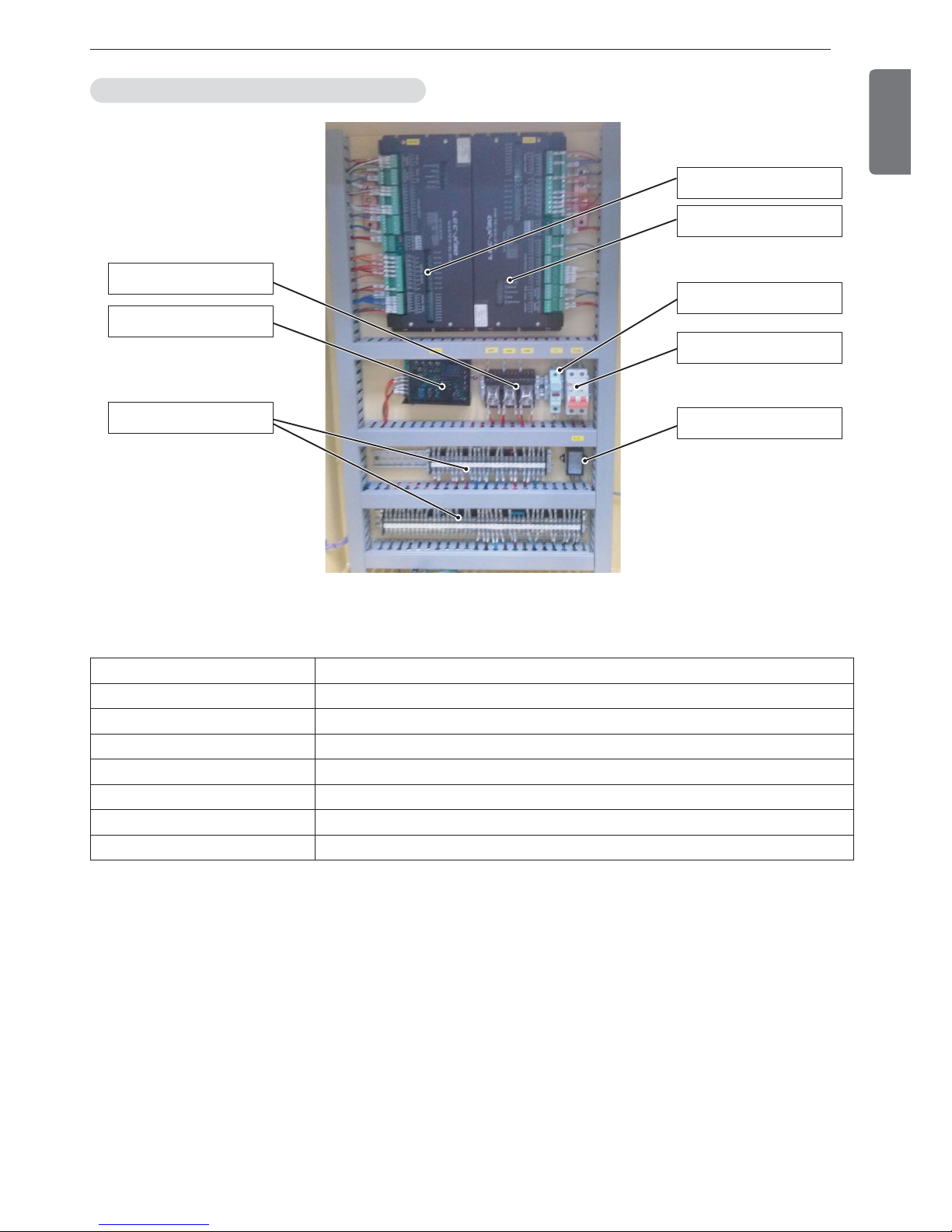
Control panel - Standard type
* The above configuration may change according to design enhancement, type, or user convenience, so please refer
to the approved drawing for details.
4. CONTROL SYSTEM
27
ENGLISH
Micom(Master Board)
Micom(Slave Board)
Fuse
CB
Noise Filter(NF)
Relay(KM1~3)
SMPS
Terminal Block(TB)
Fiqure 17. control panel
h The above configuration may change according to design enhancement, type, or user convenience, so please refer
to the approved drawing for details.
Control panel component layout - Standard type
TAG NAME USE
CB Main power(for wiring) circuit breaker
NF Micom power protection Noise Filter
SMPS Control power supply Transformer
Fuse Control power protection fuse
Realy Auxiliary relay for start
TB Terminal blocks for control signal and main power source
MICOM Control device using micro processor
28
4. CONTROL SYSTEM
ENGLISH
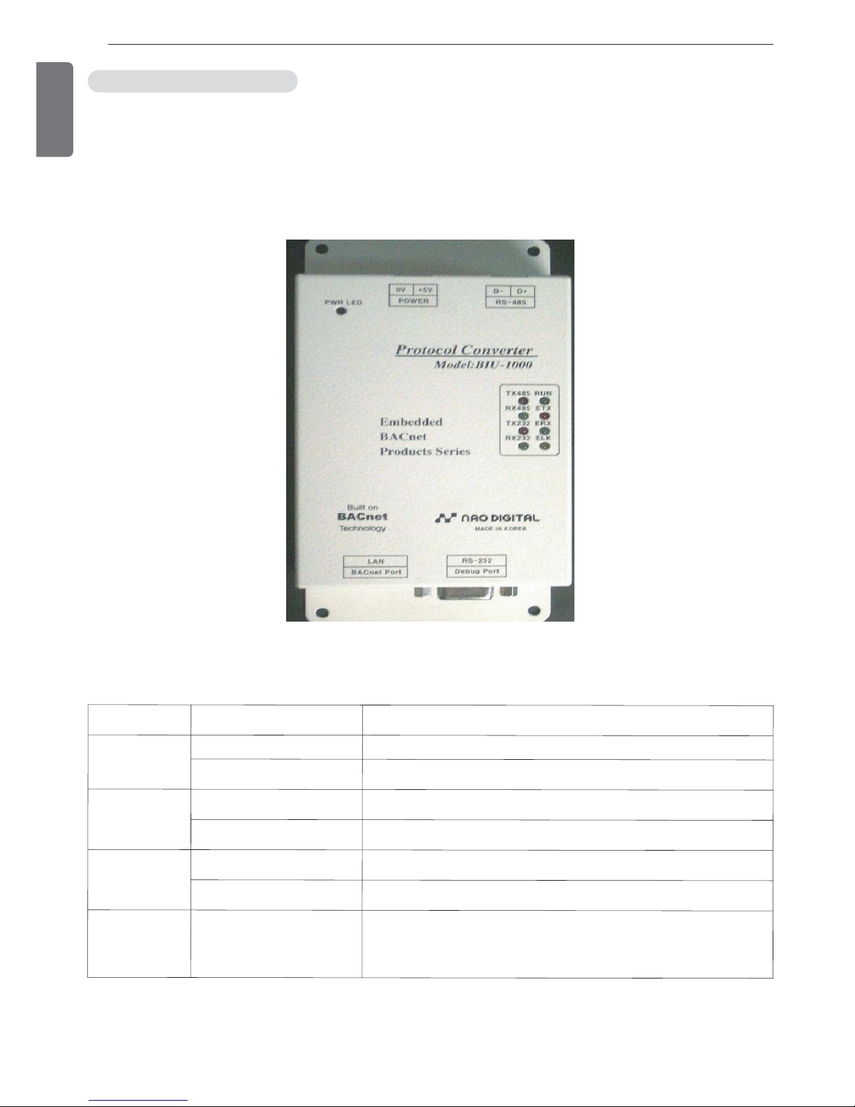
BACnet converter
Our controller basically supports Modbus communication protocol.
If the higher level communication protocol is BACnet, you need to apply a separate BACnet converter to change the
protocol.
Communication converter is attached inside the control panel.
Please refer to the following table for meaning and description of each lamp.
Optional parts related controller
Figure 18. Converter
Table 3 Converter lamp names
LED name Status Description
TX485
RX485
Flashing Normal data communication with micom
Off Error, check communication line
TX232
RX232
Flashing Normal data communication with BACnet
Off Error, check communication line
RUN
Flashing every second Board has finished Power-on test, and is normally operating
Keeping On/Off state Error, press reset button or interrupt power, and on again
ETX
ERX
ELK
Ethernet Line status LED
ELK is always On when LAN cable is connected, and ERX flashes On
when receiving, and ETX flashes On when sending data.
4. CONTROL SYSTEM
29
ENGLISH
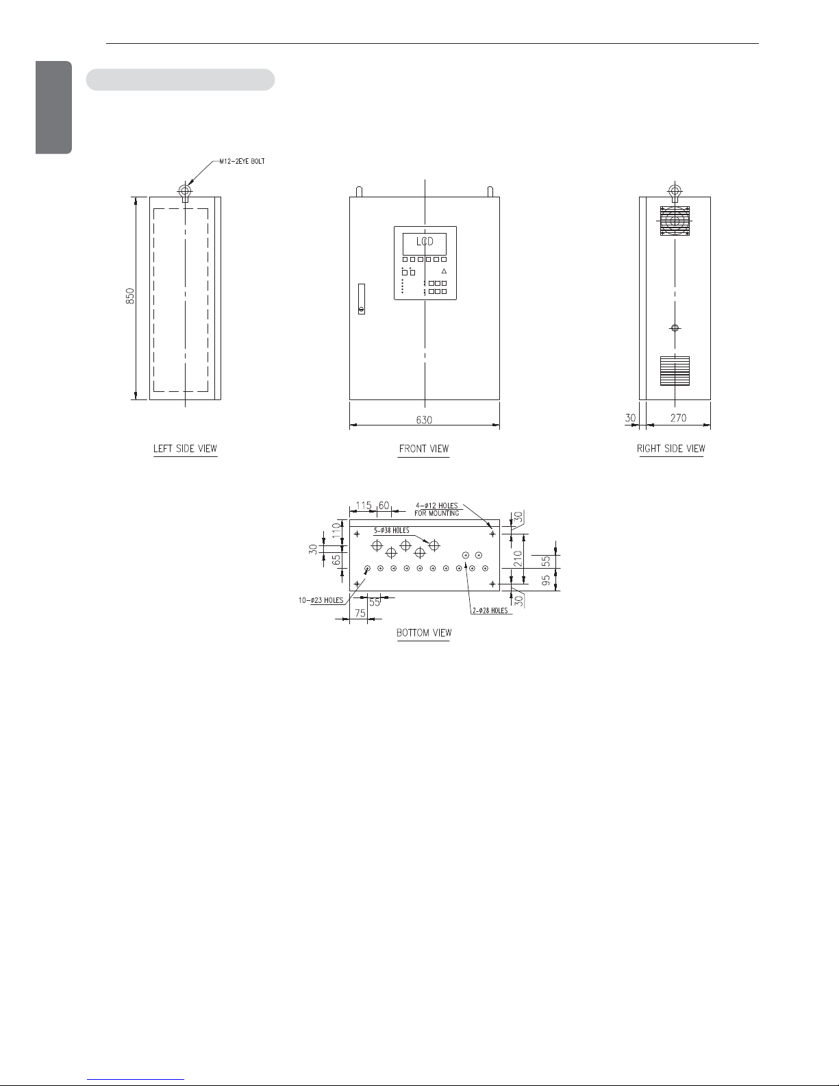
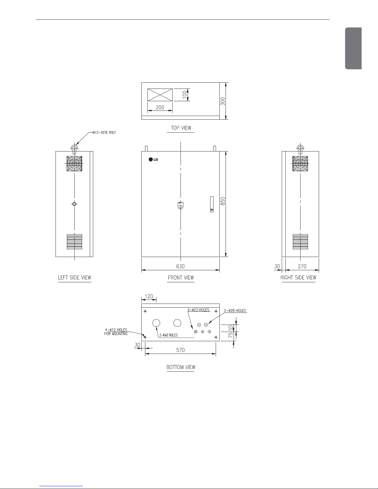
4-2. Outside view of Startup panel - Standard Type
Since the starter panel has various layouts based on starter method, option, etc., please refer to the drawing provided
together with the product.
h The above configuration may change according to design enhancement, type, or user convenience, so please refer
to the approved drawing for details.
30
4. CONTROL SYSTEM
ENGLISH
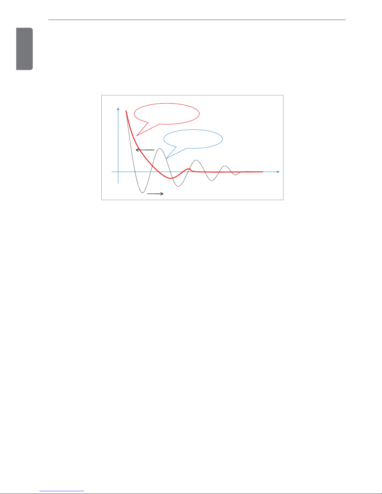
4-3. Basic control algorithm
Unique P(proportional), I(integral), and D(differential) algorithms are applied to chilled water temperature control.
Compared to the conventional method, it allows optimal control by minimizing time to approach the target value, remaining deviation, Under-Shoot and Over-Shoot during initial startup and automatic/manual conversion of operation.
Under-shoot
Over-shoot
LG’s New Control
Algorithm
General Control
Algorithm
Figure 19. Control algorithm
• Soft Loading
- Approach to the control target value with Soft startup
- Solved unnecessary stops caused by voltage change during startup
• Advanced Control
- Advanced high class control algorithm developed for high precision control compared to existing PID control
method.
- Prevention of temperature Cycling phenomenon caused by Overshoot/Undershoot during conversion from manual
mode to automatic mode.
- Reinforced safety control(Intensive Safety Control): By executing preventive control before chiller reaching abnormal stop point, it minimizes unnecessary stops of the chiller.
 Loading...