

LG LCV1100R-DP, LCV1100R-DN Installation Manual
MODELS
LCV1100R-DN / LCV1100R-DP
IR
CAMERA
TOP
COVER
SCREW
& “L”
WRENCH
INSTALLATION
MANUAL
BOTTOM
BASE
6
TEMPLATE
TOP-BALL MOUNT
TOP COVER
BOTTOM BASE
TEMPLATE
CABLE WITH
TERMINAL BLOCK
BOTTOM -
BALL MOUNT
FRONT GLASS
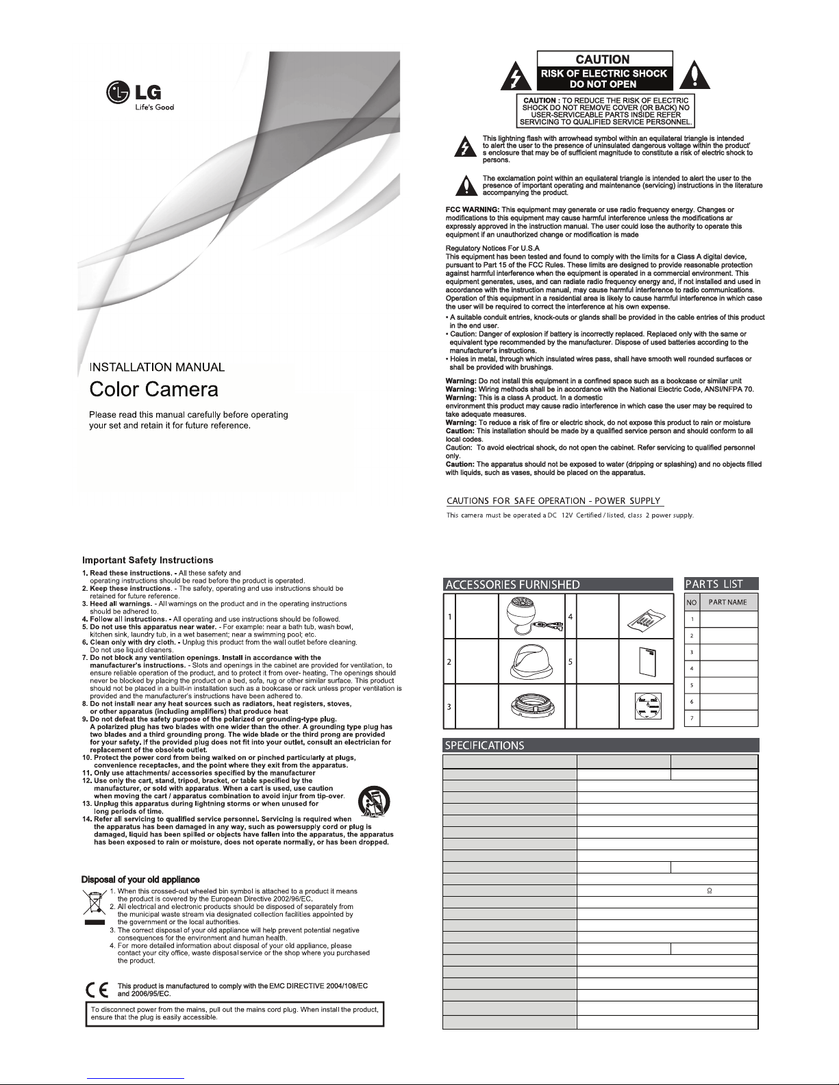
NTSC PAL
520K / 480K 610K / 570K
15.734 KHz / 59.94 Hz 15.625 KHz / 50 Hz
Auto (1/60 ~ 1/100,000) Auto (1/50 ~ 1/100,000)
1/3" 960H Interline Color CCD ( Super HAD II )
650TVL @ Color, 700TVL @ B/W
E.Effio-E
3.6mm
Color : 0.1Lux, B/W : 0 Lux (IR LED ON)
AUTO(Photo Sensor)
Internal
50dB
1Vp-p Composite (75
ש
)
24EA
AUTO
ELC
Auto (1,800 ºK ~ 10,500 ºK)
DC 12V (4.5W)
-10ԕC ~ 50ԕC / 0% ~ 80%RH
-20ԕC ~ 60ԕC / 0% ~ 85%RH
(100 + 70)Ø x 70(H) (mm)
430 g
AUTO
Signal System
Total / Effective Pixels No.
Imaging Sensor
Horizontal Resolution
Image Signal Processor
Lens Type
Minimum Illumination (30 IRE)
Day & Night
Sync. System
Scanning Frequency (H/V)
S/N Ratio
Video Output Signal
IR LED
IR OPTIMIZER
Exposure
Auto Gain Control
Electronic Shutter Speed
White Balance
Power Source
Operating Temperature/Humidity
Storage Temperature/Humidity
Dimension
Weight
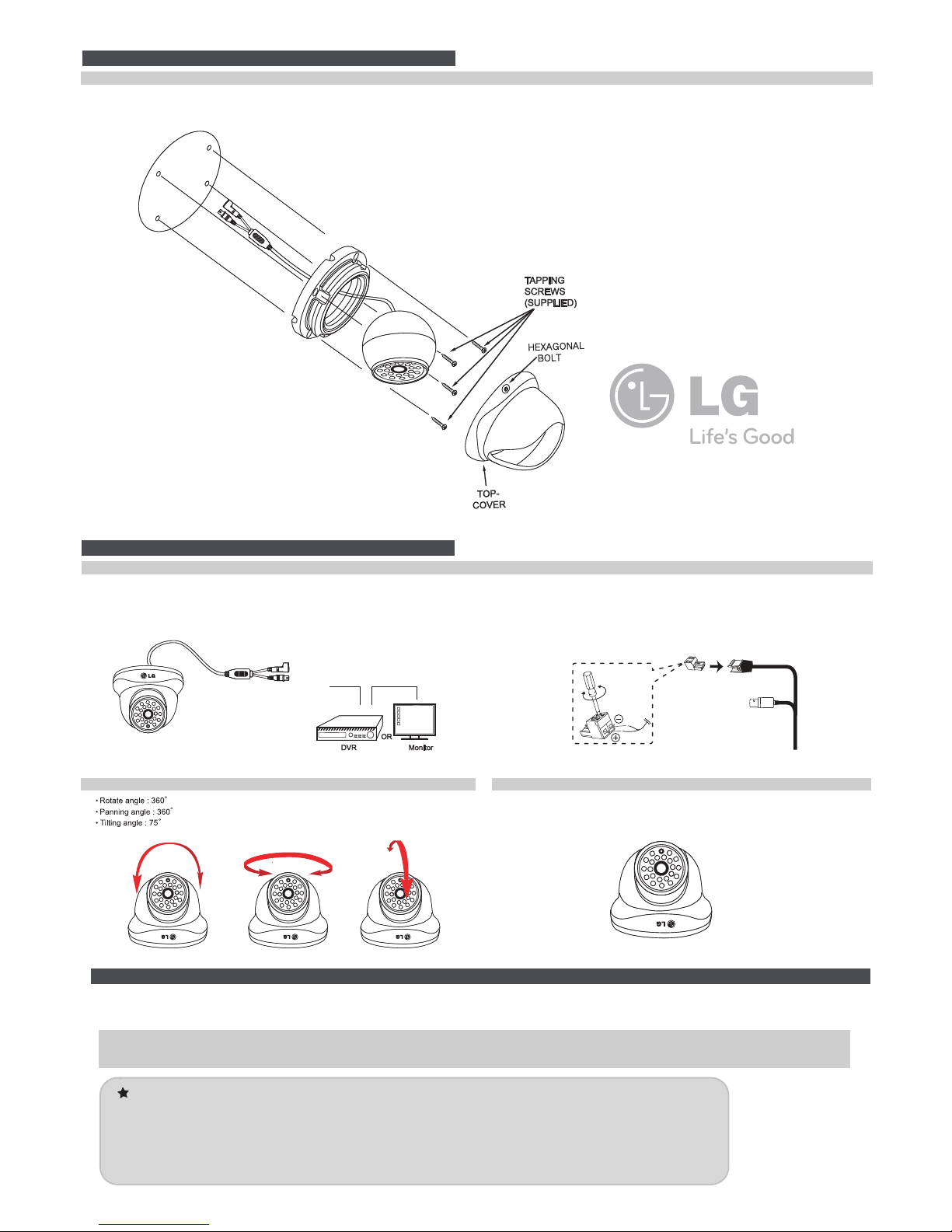
1. Affix the mounting template(supplied) to the mounting surface. 2. Secure the camera mounting base to the position where the camera
should be mounted with the supplied tapping screws.
(Please leave a good position of cable not to interrupt the survelliance
area with it when installing.)
3. Adjust desired scene by turning and moving the direction of he ball
mount camera and cover the top-cover.
4. Then you can fix it to screw-down the hexagonal bolt with the supplied
“L” wrench.
POWER
INPUTDC12V
VIDEO
OUTPUT
ROTATING
PANNING
TILTING
2. Lens Focus Adjustment1. Having a better view , adjust the camera
* The Lens is focused far from 1M when ex-factory.
Therefore we recommend the lens focus as is.
WARNINGS & CAUTIONSWARNINGS & CAUTIONS
The information is provided to ensure your safety and to prevent any losses, financial or otherwise. Please read it
carefully and use the product accordingly.
* For productinquires, please contact the retail shop where you bought the camera. The use of equipment such as
an aerial ladder while providing after-sales service shall be at your expense.
NOTES
* Please make sure the product is installed appropriate places where secured from flood,
such as under the eaves, to operate properly.
* This product is certified as IP66 standard. However, if there is any flood concerns, you shall
ask the service center if it would be OK to install where you want.
P/N : COV00000000
video output
power input
Connect power jack in green to the power supply
and video jack in yellow to the monitor(or DVR if available)
CONNECTION & ADJUSTMENTCONNECTION & ADJUSTMENT
CONNECTION
Connecting power source
Connect a power source to the input terminal correctly. You can see
“+”, “_” on the plug of the cable. You can refer to connect a power source
to the power input terminal as shown below.
INSTALLATION
Installing the camera on a ceiling or wall
 Loading...