

LG LCN380CP, LCU240CP, LCU380CP, LCN240CP Service Manual

LG
Ceiling Cassette
Air Conditioner
SERVICE MANUAL
LG
CAUTION
website http://www.lgservice.com
e-mail http://www.lgeservice.com/techsup.html
• BEFORE SERVICING THE UNIT, READ THE SAFETY
PRECAUTIONS IN THIS MANUAL.
• ONLY FOR AUTHORIZED SERVICE PERSONNEL.

2 Ceiling Cassette Air Conditioner
TABLE OF CONTENTS
Table of contents Page
1. Models List .......................................................................................................................3
2. Safety Precautions ...........................................................................................................4
3. Feature & Benefits ...........................................................................................................8
4. List of Functions .............................................................................................................11
5. Function of Remote Control ...........................................................................................12
6. Specifications .................................................................................................................14
7. Dimensional Drawings ...................................................................................................16
8. Wiring Diagrams.............................................................................................................20
9. Refrigerant Cycle Diagrams ...........................................................................................22
10. Installation ....................................................................................................................23
11. Trouble Shooting Guide................................................................................................33
12. (3-Way)Valve ................................................................................................................49
13. Electronic Control Device.............................................................................................53
14. Exploded View and Replacement Parts List ................................................................54

Models List
Service Manual 3
Nominal Capacity
Indoor Units Outdoor Units Power Supply
Btu/h Type Model Name Model Name Ø,V,Hz
24K Ceiling Cassette LCN240CP LCU240CP
1Ø, 208-230V, 60Hz
38K Ceiling Cassette LCN380CP LCU380CP
1.1 Cooling Only
Models List
Safety Precautions
4 Ceiling Cassette Air Conditioner
Safety Precautions
To prevent injury to the user or other people and property damage, the following instructions must
be followed.
■ Incorrect operation due to ignoring instruction will cause harm or damage. The seriousness is
classified by the following indications.
■ Meanings of symbols used in this manual are as shown below.
This symbol indicates the possibility of death or serious injury.
This symbol indicates the possibility of injury or damage to properties only.
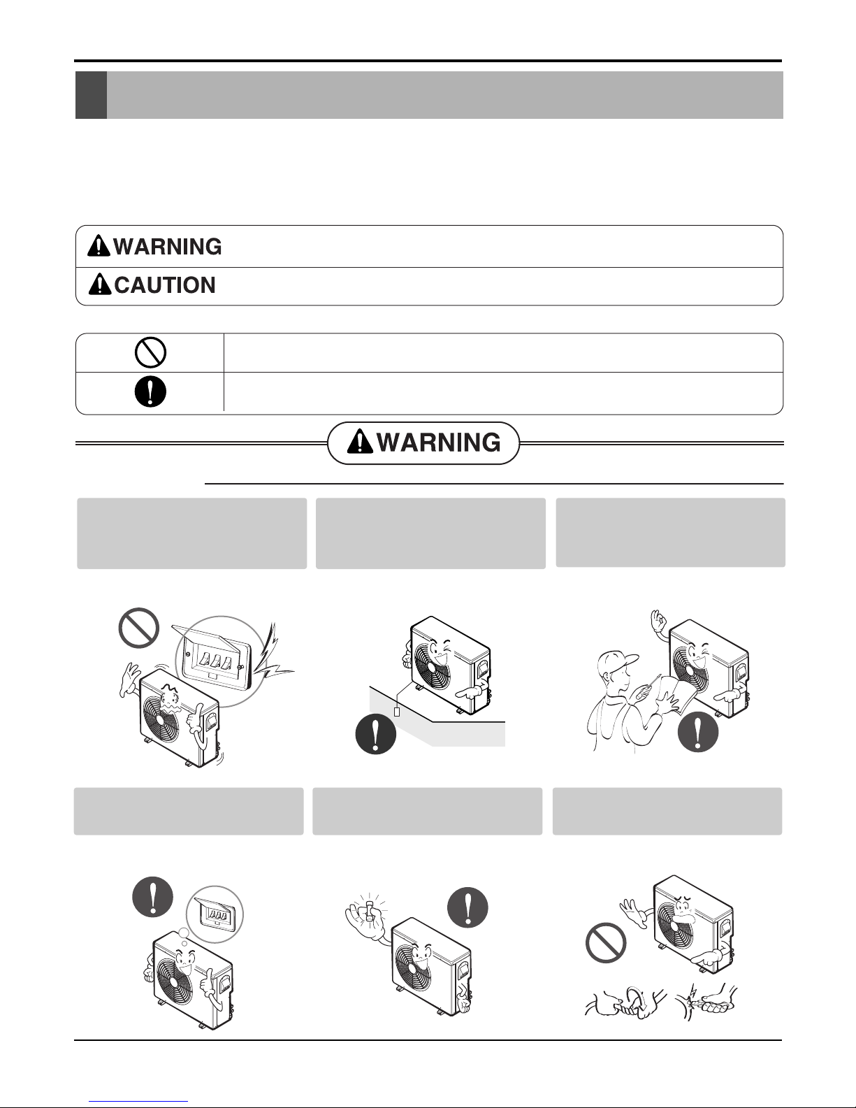
■ Installation
Be sure not to do.
Be sure to follow the instruction.
Do not use a defective or underrated circuit breaker. Use this
appliance on a dedicated circuit.
• There is risk of fire or electric
shock.
Always ground the product.
• There is risk of fire or electric
shock.
Install the panel and the cover
of control box securely.
• There is risk of fire or electric
shock.
Always install a dedicated circuit and breaker.
• Improper wiring or installation may
cause fire or electric shock
Use the correctly rated breaker or fuse.
• There is risk of fire or electric
shock.
Do not modify or extend the
power cable.
• There is risk of fire or electric
shock.
Safety Precautions
Service Manual 5
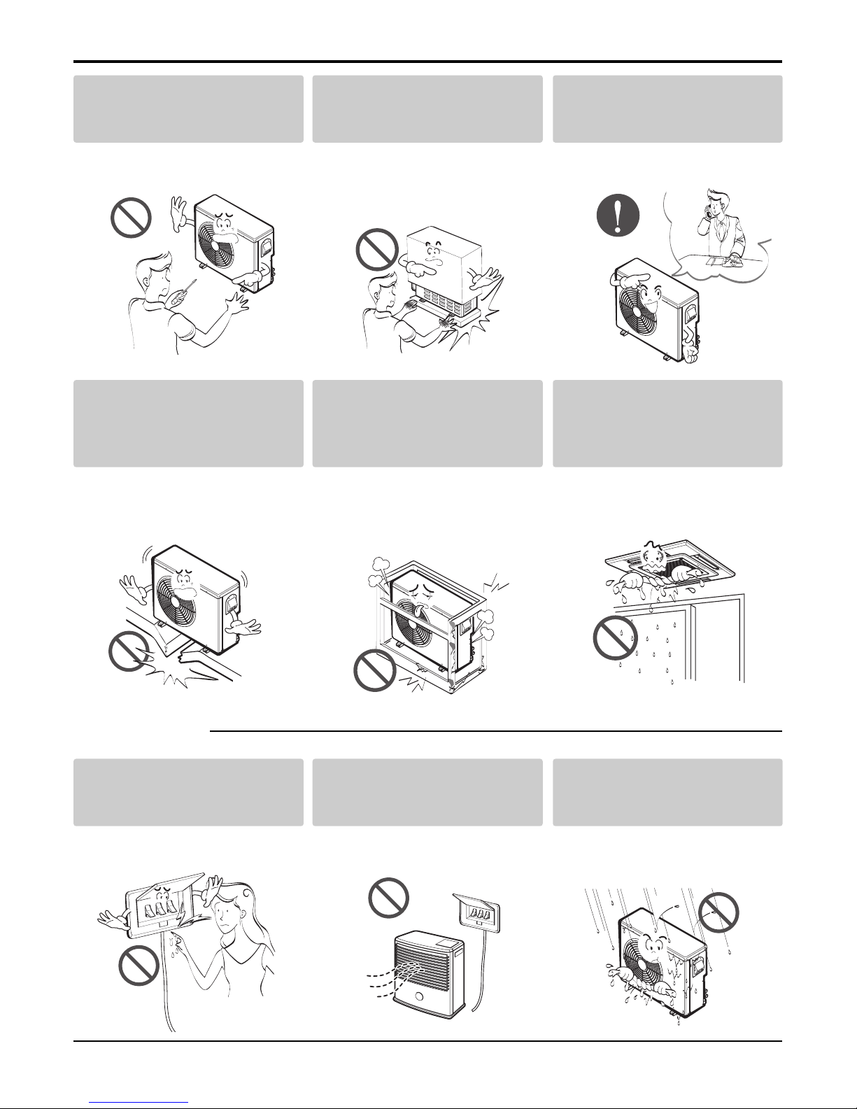
■ Operational
Do not install, remove, or reinstall the unit by yourself
(customer).
• There is risk of fire, electric shock,
explosion, or injury.
Be cautious when unpacking
and installing the product.
• Sharp edges could cause injury.
Be especially careful of the case
edges and the fins on the condenser and evaporator.
For installation, always contact the dealer or an
Authorized Service Center.
• There is risk of fire, electric shock,
explosion, or injury.
Do not install the product on a
defective installation stand.
• It may cause injury, accident, or
damage to the product.
Be sure the installation area
does not deteriorate with age.
• If the base collapses, the air conditioner could fall with it, causing
property damage, product failure,
and personal injury.
Do not let the air conditioner
run for a long time when the
humidity is very high and a
door or a window is left open.
• Moisture may condense and wet or
damage furniture.
Do not touch(operate) the
product with wet hands.
• There is risk of fire or electrical
shock.
Do not place a heater or other
appliances near the power
cable.
• There is risk of fire or electric
shock.
Do not let electric parts of the
product get wet.
• There is risk of fire, failure of the
product, or electric shock.
Safety Precautions
6 Ceiling Cassette Air Conditioner
■ Installation
Do not open the inlet grill of the product during
operation. (Do not touch the electrostatic filter,
if the unit is so equipped.)
• There is risk of physical injury, electric shock, or product failure.
Be cautious that water could not enter the
product.
• There is risk of fire, electric shock, or product damage.
Always check for gas (refrigerant) leakage after
installation or repair of product.
• Low refrigerant levels may cause failure of product.
Install the drain hose to ensure that water is
drained away properly.
• A bad connection may cause water leakage.
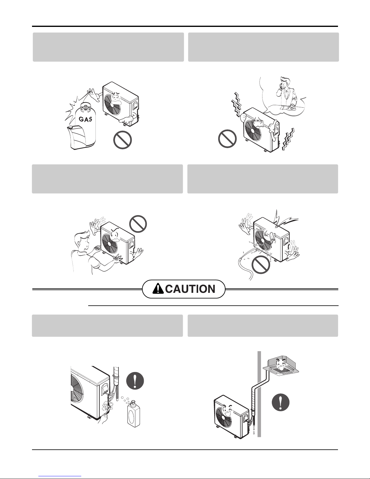
Do not store or use flammable gas or combustibles near the product.
• There is risk of fire or failure of product.
If strange sounds, or small or smoke comes
from product. Turn the breaker off or disconnect the power supply cable.
• There is risk of electric shock or fire.
Gasolin
Safety Precautions
Service Manual 7
Keep level even when installing the product.
• To avoid vibration or water leakage.
Use two or more people to lift and transport
the product.
• Avoid personal injury.
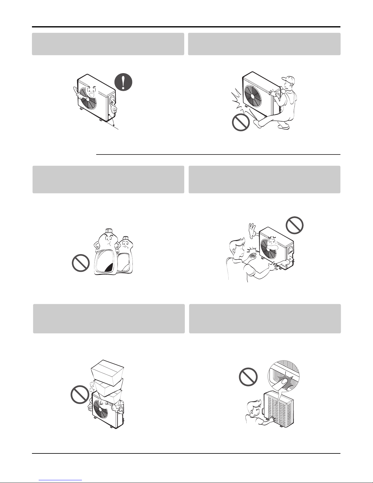
Use a soft cloth to clean. Do not use harsh
detergents, solvents, etc.
• There is risk of fire, electric shock, or damage to the
plastic parts of the product.
Do not touch the metal parts of the product
when removing the air filter. They are very
sharp!
• There is risk of personal injury.
Do not step on or put anyting on the product.
(outdoor units)
• There is risk of personal injury and failure of product.
Do not insert hands or other objects through
the air inlet or outlet while the product is operated.
• There are sharp and moving parts that could cause
personal injury.
90˚
Wax
Thinner
■ Operational
8 Ceiling Cassette Air Conditioner
Features & Benefits
Environment Friendly Refrigerant :
- LG Ceiling Cassette Air Conditioners uses environment friendly refrigerant, which don't do any harm to
the environment.
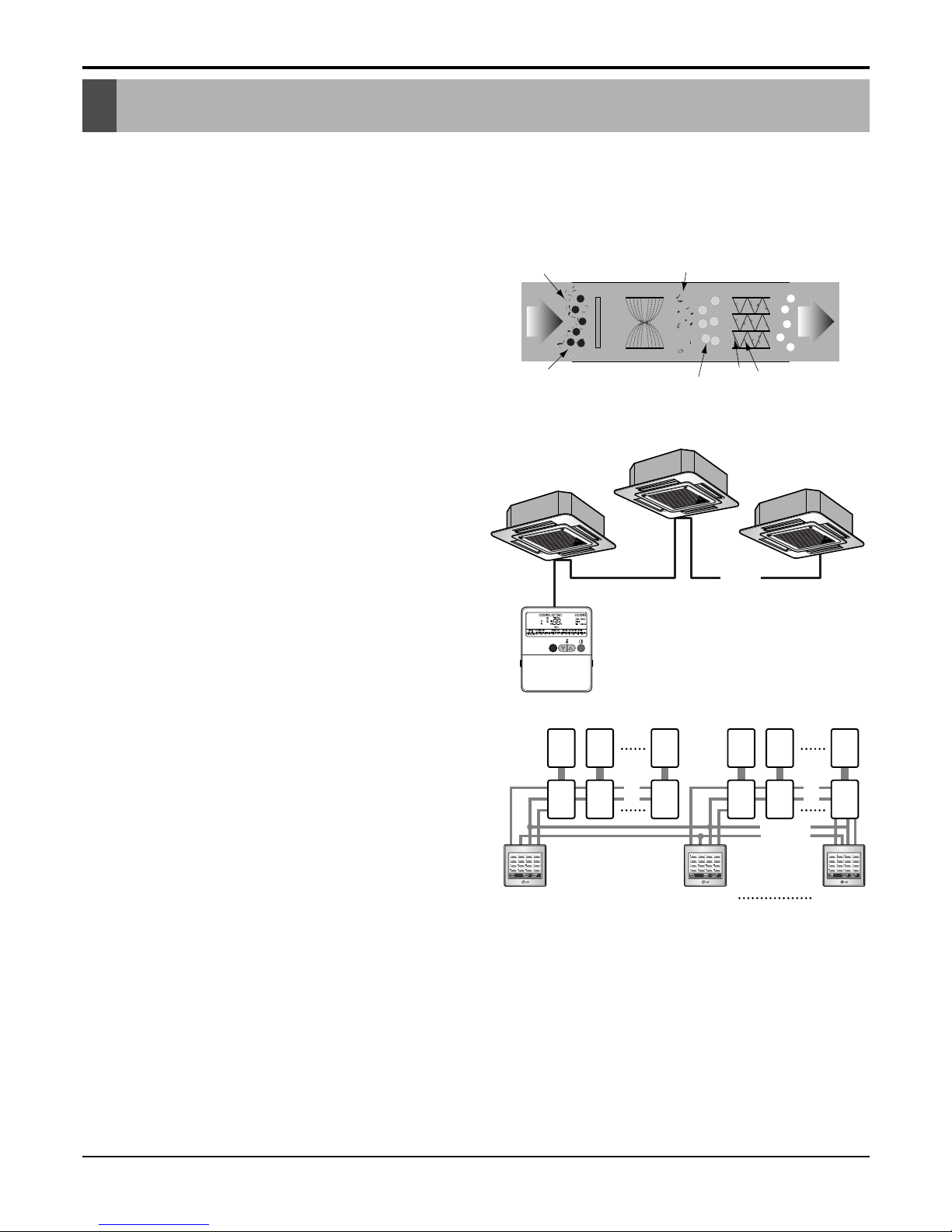
Plasma Air Purifier :
- It removes not only microscopic contaminants &
dust, but also house mites, pollen, and pet fur to help
preventing allergic diseases like asthma.It provides
odor free, dust free and allergy free air.
Group Control :
- It enables to control as much as 16 units with the
help of one wired remote controller. All the units will
follow same setting of temperature & other sub functions.
Central Control :
- It enables to control 16 x 8 = 128 units with the help
of 8 controllers. All units can be put on and off from
one Central Room. For Setting Temperature, Fan
Speed and other sub functions, access the respective LCD wired remote controller of each unit.
Jet Cool :
-In this mode, quick and fast cooling is done. Cold and
high velocity air is supplied to the room till the indoor
temperature reaches 18°C. The unit will continue to
run in jet cool mode till the Indoor temperature reaches 18°C.
12 16........
........
IonizerPre-filter
Dust particles
dusts
Odour
Dust
electrode
discharge
Odor molecule
+6.5KV
discharge
aluminum coated
electrode(-)
(3.25KV discharge)
Generating
plasma
+
+
+
+
+
Dusts Collection
Polluted
Air
Purified
fresh Air
Main
PCB
Controller
# 1
Controller
# 2
Controller
# 8
M
1
Sub
1
M
2
Sub
2
M
16
Sub
16
M
17
Sub
17
M
18
Sub
18
M
128
Sub
128
Features & Benefits
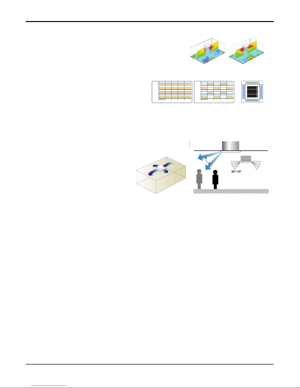
Swirl Swing
- It is the function for comfort cooling/heating operation.
- The diagonal two louvers are opened the
more larger than the other louvers.
After one minute, it is opposite.
Space Control
Vanes angle can be controlled by pair, considering its
installation environment.
- For example direct drafts can be annoying, leading
to discomfort and reduced productivity vane control
helps to eliminate this problem.
- Easily controlled by wired remote control.
- Air Flow can be controlled easily regarding any
space environment.
Auto Restart Operation :
- Whenever there is electricity failure to the unit, and after resumption of the power, unit will start in the same
mode prior to the power failure. Memorized condition are on / off condition, operating mode (cooling/heating),
set temperature and fan speed.The unit will memorize the above conditions and start with same memorized
condition.
Two Thermistor Control :
- There may be a significant difference between the temperature taken at the installed product and indoor temperature. Two thermistor control provides option to control temperature by referring any of the two temperatures. With the help of the slide switch at the back of the LCD wired remote controller, selection of the desired
thermistor for controlling the unit can be done. One thermistor is in the Indoor unit & the other one is in the
LCD wired remote.
Service Manual 9
Features & Benefits
71
Vane 2
Swirl Swing(New)4- Open(Conventional)
Swirl Swing(New)4- Open(Conventional)
2.4% 4.8%100% Improved
Comparison of Air Flow Types
Comparison of Floor
Temp. Distribution(20°C)
Vane 1 Close OpenOpen
Open
Open
Open
Close CloseOpen
Vane 3 Close Open Close CloseOpen
OpenOpen Close CloseOpen
Vane 2
OpenOpen
Time
Close CloseOpen
Vane 4
Vane 1
Vane 3
Vane 2
Time
Vane 4
Vane 3
Vane 4
Vane 1
10 Ceiling Cassette Air Conditioner
Features & Benefits
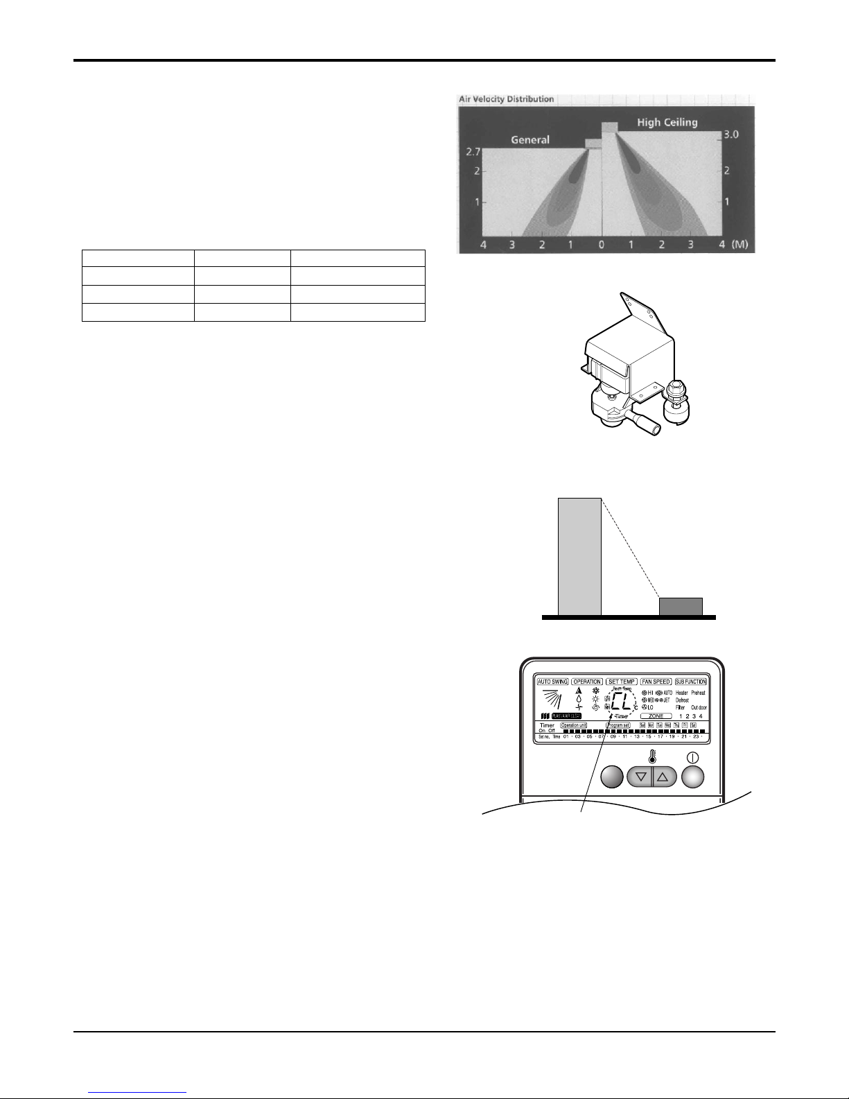
High Ceiling Operation
- According to the height of ceiling installation, it provides variability of indoor fan motor rpm. If the height
of installation is low then you can adjust low rpm of
indoor fan motor. On the other hand if the height of
the installation is high you can adjust high rpm of
indoor fan motor. Selection of speed can be done by
slide switch at the back of the LCD wired remote.
ex:
Water Drain Pump :
- In some of the places natural drainage is not possible. For such places drain pump is very useful. It
removes condensed water from the unit.
Time Delay Safety Function :
- It delays restarting of the compressor by three minutes thereby preventing damage to the compressor.
Zero Standby Power:
- Due to SMPS (Switching Modulation Power Supply)
technology, there is almost zero power consumption
in the standby mode.
Child Lock Function:
-It prevents the children or others from tampering the
control buttons. Unit can be controlled by the wireless
remote controller. This can be easily set by pressing
timer key & Min key simultaneously. After child lock is
set, pressing any key will displaye CL on the LCD for
3 seconds and all the keys will be ineffective.
Self Diagnosis Function:
- This function provides diagnosis of the unit. An
error code will be displayed on the LCD wired
remote controller & diagnosis can be done as per
the code indication. The same is also printed on
key cover of the LCD wired remote controller.
5~6W
Others LG
0.5W
CHILD LOCK
-Display
Selection Height RPM
Lower 2.4m 700/600/500
Standard 2.7m 750/650/550
Higher 3.0m 800/700/600

Service Manual 11
List of Functions
• Ceiling Cassette
Model Ceiling Cassette
Features
Air Discharge Outlet 4 4
Airflow Direction control (left & right) - Airflow Direction control (up & down) Auto Auto
Airflow Steps(Fan / Cool /Heat) 3/4/- 3/4/Auto Changeover - Auto Operation o o
Auto Restart Operation o o
Auto Swing o o
Central Control Accessory Accessory
CHAOS Wind (Auto wind) - Child Lock Function o o
Cooling & Fan Operation o o
Coolling, heating & Fan Operation - Defrost / Deicing - Deodorizing Filter - Drain Pump o o
E.S.P. Control - Electric Heater - Energy Saving Gold Fin - Environment Friendly Refrigerant o o
Fire Alarm Function - Forced Operation o o
Group Control o o
High Ceiling Operation o o
Hot Start - Jet Cool - Low Ambient Control - Plasma Air Purifier Optional Optional
Prefilter(Washable / Anti-fungus) o o
Restart Delay (3-minutes) o o
Self Diagnosis o o
Sleep Mode o o
Soft Dry Operation o o
Swirl Swing o o
Tele Control - Temperature Control o o
Test Function o o
Time Delay Safety function o o
Timer (weekly) o o
Two Thermistor Control o o
Space Control o o
Wired LCD Remote Controller o o
Wireless Remote Controller o o
Zero Standby Power o o
Zone Control - -
LC240CP LC380CP
Notes :
O : Basic
Optional : Factory-Installed
Accessory : Field-Installed
- : Not available on this system
List of Functions
12 Ceiling Cassette Air Conditioner
Function of Remote Control
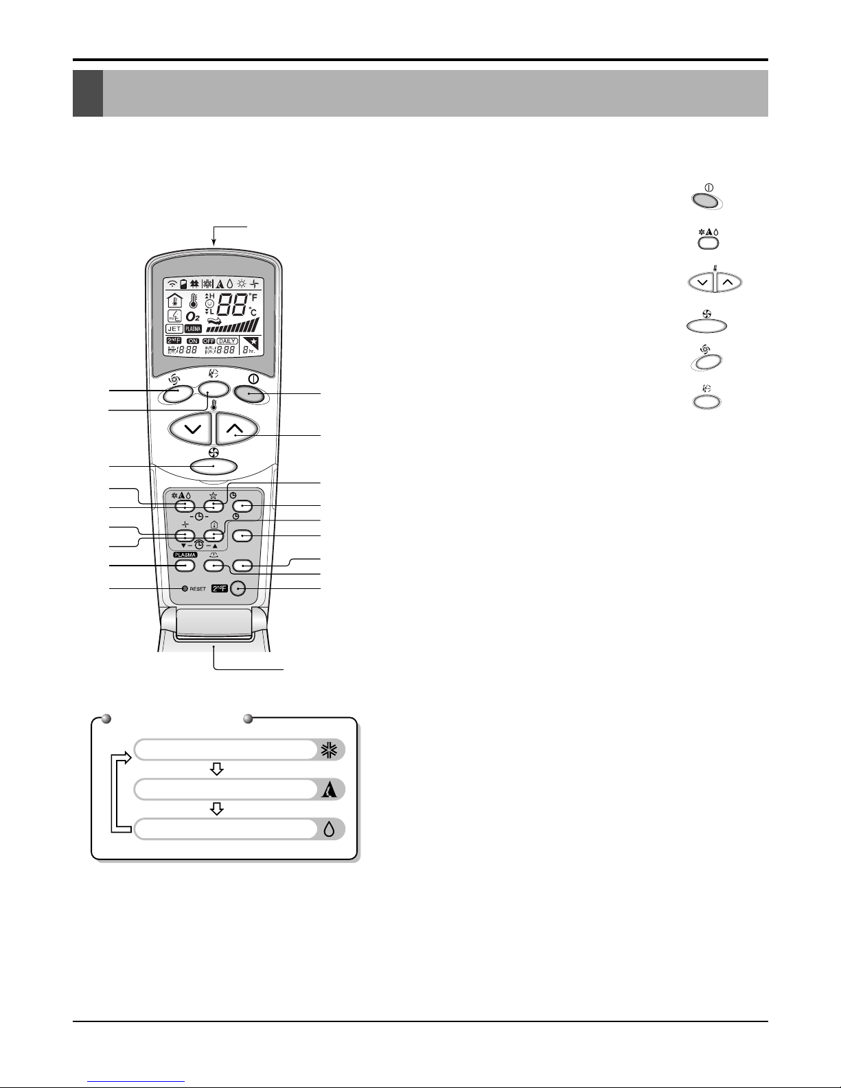
1. Wireless LCD Remote Control
Function of Remote Control
Cooling Operation
Auto Operation
Healthy Dehumidification Operation
Operation Mode
ON
OFF
CANCEL
SET
°C/°F
AUTO CLEAN
1
3
5
4
9
10
12
18
16
7
2
8
13
15
11
6
Flip-up door
(opened)
Signal transmitter
17
14
1. START/STOP BUTTON
Operation starts when this button is pressed and
stops when the button is pressed again.
2. OPERATION MODE SELECTION BUTTON
Used to select the operation mode.
3. ROOM TEMPERATURE SETTING BUTTONS
Used to select the room temperature.
4. INDOOR FAN SPEED SELECTOR
Used to select fan speed in four steps
low, medium and high.
5.
JET COOL
Used to start or stop the speed cooling.(speed cooling
operates super high fan speed in cooling mode.)
6. AUTO SWING BUTTON
Used to stop or start louver movement and set the
desired up/down airflow direction.
7. ON/OFF TIMER BUTTONS
Used to set the time of starting and stopping operation.
8. TIME SETTING BUTTONS
Used to adjust the time.
9. TIMER SET/CANCEL BUTTON
Used to set the timer when the desired time is
obtained and to cancel the Timer operation.
10. SLEEP MODE AUTO BUTTON
Used to set Sleep Mode Auto operation.
11. AIR CIRCULATION BUTTON
Used to circulate the room air without cooling.
12. ROOM TEMPERATURE CHECKING BUTTON
Used to check the room temperature.
13. PLASMA AIR CLEAN BUTTON
Used to start or stop the plasma-purification function.
14. HORIZONTAL AIRFLOW DIRECTION CONTROL
BUTTON (OPTIONAL)
Used to set the desired horizontal airflow direction.
15. RESET BUTTON
Used prior to resetting time.
16. 2nd F Button
Used prior to using modes printed in blue at the bottom of buttons.
17. AUTO CLEAN (OPTIONAL)
Used to set Auto Clean mode.
18. °C/°F SWITCH BUTTON
Used to switch temperature reading from Centigrade
to Fahrenheit.
❈ The wireless remote controller do not operate the swirl mode.❈ The wireless remote controller do not operate the swirl mode.
Service Manual 13
Function of Remote Control
Timer Cancel 2ndF
Program Week
Hour Min
Holiday
Set/Clr
RESET
Plasma
Operation unit
Humidify
AUTO SWING OPERATION
FAN SPEED
Program set
SUB FUNCTION
SET TEMP
Room Temp
HI
MED
LO
Heater
Defrost
Filter
Preheat
Out door
Time
Timer
On
Set no. Time
Off
01 03 05 07 09 11 13 15 17 19 21 23
3
10
12
14
15
11
13
18
16
2
1
5
4
8
9
7
17
1234
ZONE
2ndF
No Func
AUTO
JET
SLo
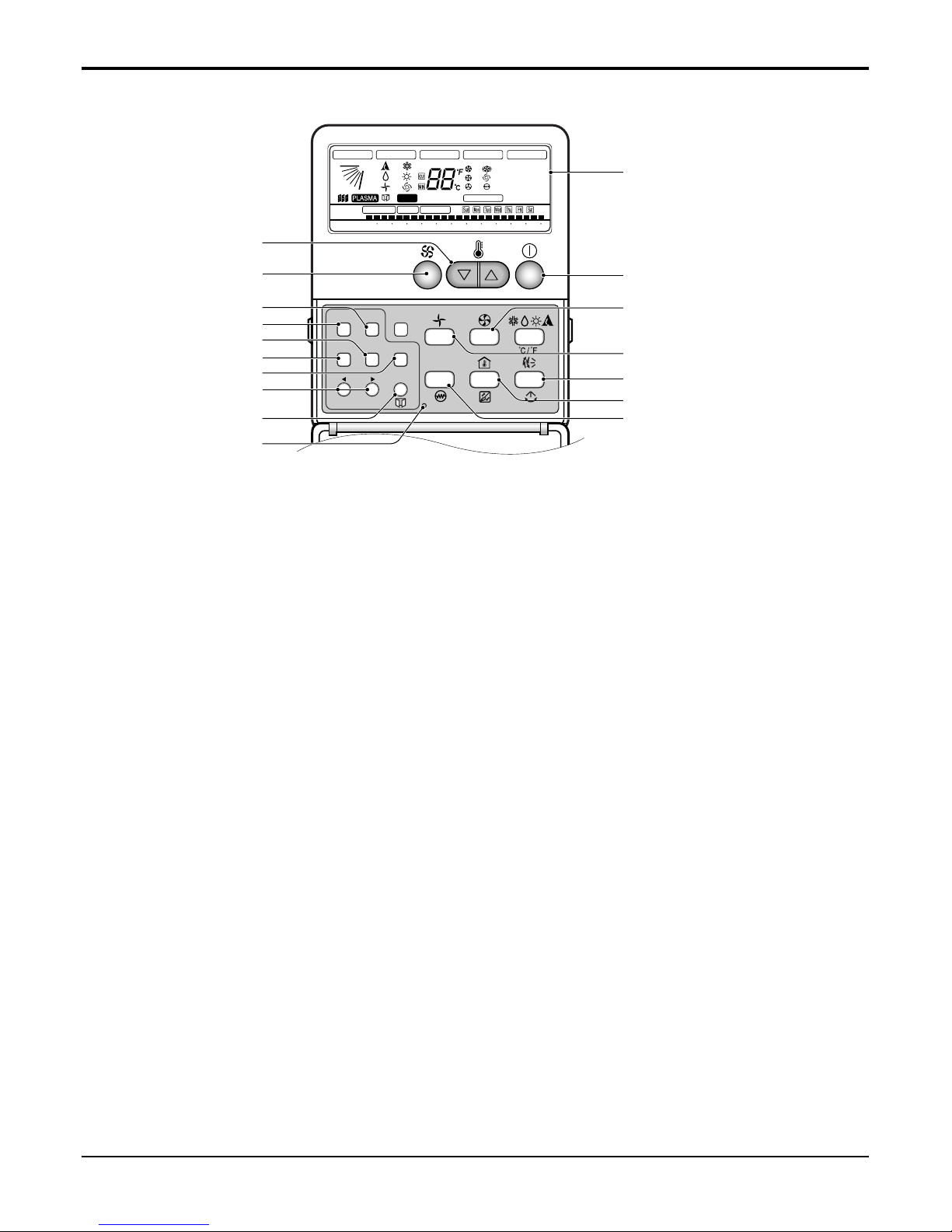
1 Operation display
Displays the operation conditions.
2 On/Off Button
Operation starts when this button is pressed, and
stops when the button is pressed again.
3 Set Temperature Button
Used to set the temperature when the desired temperature is obtained.
4 FAN Operation Button
Used to circulate room air without cooling.
5 Fan Speed & Jet Cool Button
Used to set the desired fan speed and select jet
cool mode.
6 Operation Mode Selection Button
Used to select the operation mode.
• Auto Operation Mode
• Cooling Operation Mode
• Soft Dry Operation Mode
7 Auto Swing Button
Used to swing up and down.
8 Room Temperature Checking Button
Used to check the room temperature.
9 Plasma Air Clean Button
Used to start or stop the plasma-purification function.
10 Timer Cancel Button
Used to cancel the timer.
11 Timer Set Button
Used to set the timer when the desired time is
obtained.
12 Week Button
Used to set a day of the week.
13 Program Button
Used to set the weekly timer.
14 Holiday Button
Used to set a holiday of the week.
15 Time Set Button
Used to set the time of the day and change the
time in the weekly timer Function.
16 Set and Clear Button
Used to set and clear the weekly timer.
17 Swirl Button
Used to select swirl swing mode.
18 Reset Button
Used to set the current time and clear the setting
time.
2. Wired LCD Remote Control
❈ The wireless remote controller do not operate the swirl
mode.
14 Ceiling Cassette Air Conditioner
3 * 2.1
4 * 2.1
1 / 4 (6.35)
1 / 2 (12.7)
7.5
30/15
ø25
-
7,034(6,048)
24000
-
-
2500
11.5
1, 208-230, 60
93
2.81(2.42)
9.6
-
-
18~30(64-86)
3.3
Capillary Tube
LCN240CP
LCU240CP
PT-CFC
Cooling Capacity
W(kcal/h)
Btu/h
Heating Capacity
W(kcal/h)
Btu/h
Input Cooling/Heating W
Running Current Cooling/Heating A
Power Supply ø,V,Hz
Power Factor %
E.E.R Cooling
W/W(kcal/hW)
Btu/hW
C.O.P Heating
W/W(kcal/hW)
Btu/hW
Setting Temperature Range(cool/heat) °C
Dehumidification Rate l/h
Refrigerant Control
Refrigerant Charge g(oz), type
System
Indoor Unit
Outdoor Unit
Decoration Panel
Indoor Unit LCN240CP
Output W
Model
Indoor fan motor
No. of Poles
Input W
Running Current A
Capacitor µF/Vac
Indoor Fan
Type
No. Used / Diameter EA/mm(inch)
Indoor Fan RPM
Cooling(H/M/L) rpm
Heating(H/M/L) rpm
Air Circulation Indoor (H/M/L) CMM(CFM)
Noise Level
(Sound Press,1m)
Indoor(H/M/L) dB(A)±3
Temperature Controller
Tube Size (OD) inch(mm)
Indoor Coil Fins per inch
No. of Rows & Column
Indoor inch(mm)
Dimensions (W*D*H)
Panel inch(mm)
Net Weight Indoor kg(lbs)
Outdoor Unit LCU240CP
Locked Rotor Amp. A
Type
Quantity No.
Model
Maker
Compressor Capacity W(Btu/h)
Motor Type
Motor Input W
Oil Type
Oil Charge cc
O.L.P Type(Model Name)
Tube Size (OD) inch(mm)
Outdoor Coil Fins per inch
No. of Rows & Column
Output W
Model
Outdoor fan motor
No. of Poles
Input W
Running Current A
Capacitor µF/Vac
Type
Outdoor Fan
No. Used / Diameter EA/inch(mm)
Discharge Side / Top
Speed rpm
Air Circulation Outdoor CMM(CFM)
Noise Level
(Sound Press,1m)
Outdoor dB(A)±3
SVC Valve
Liquid
inch(mm)
Gas
Dimensions (W*H*D) Outdoor inch(mm)
Net Weight Outdoor kg(lbs)
Others
Power Supply Cable(With Earth Cable)
No.* mm
2
Conncecting Cable(With Earth Cable)
Connecting Tube
Liquid Side inch(mm)
(ø. Socket Flare)
Gas Side inch(mm)
Length, std m
Max length/elevation m
Drain hose (ID ø)
Indoor Unit mm
Outdoor Unit mm
40.3
6
121
0.53
4.0/ 440
Turbo Fan
1/382(15)
600 / 540 / 480
-
15.0/14.0/13.0(530/494/459)
43/41/39
Thermistor
0.275(7)
21
2R 12C
29.3*29.4*11.5(744*744*292)
33.5*33.5*1.18(850*850*30)
24(52.9)
62
Rotary
2
GK120K
LG
3,531(12,050)
PSC
1220
FVC68D
700
External
0.275(7)
20
2R 36C
67.2
6
120
0.54
6 / 370
Propeller
1/18.1(460)
Side Discharge
850
58(2048)
55
1 / 4 (6.35)
1 / 2 (12.7)
34.2*25.8*12.6(870*655*320)
57(125.6)
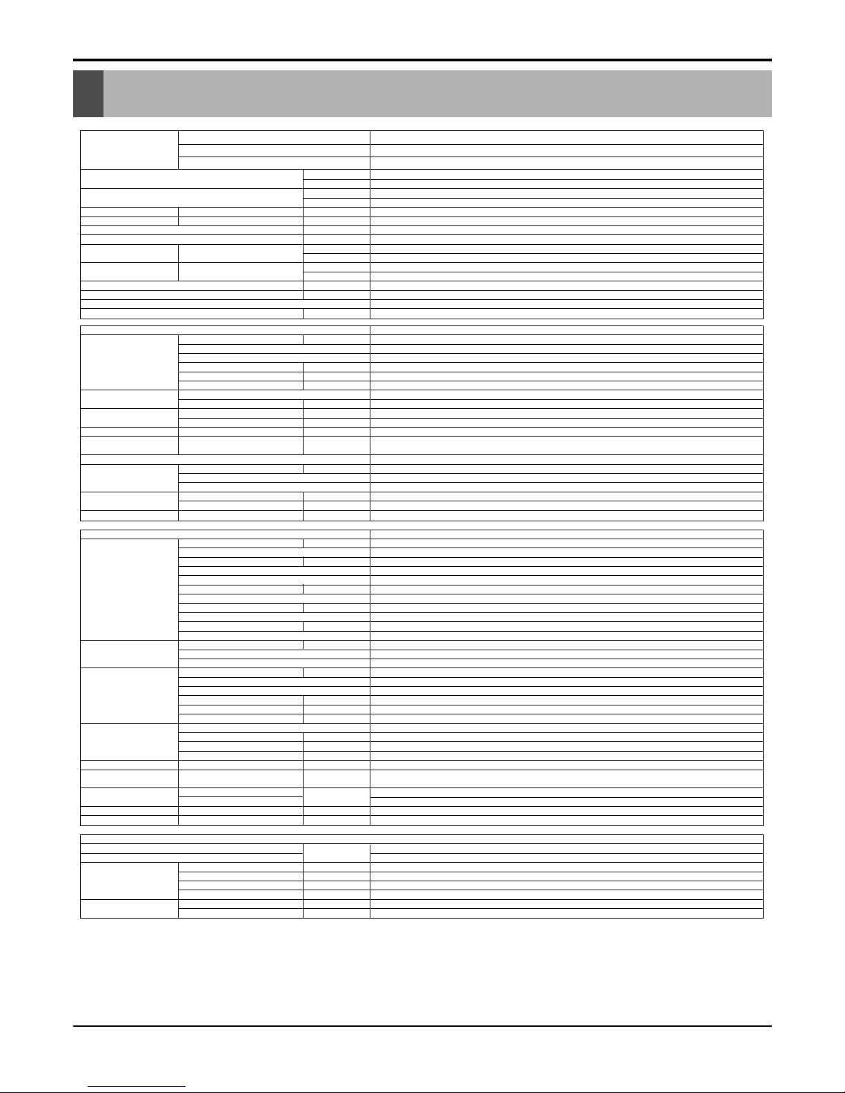
Specifications
Specifications
Notes: 1. Capacities are based on the following conditions:
Cooling: - Indoor Temperature 26.7°C(80.0°F) DB /19.4°C(67.0°F) WB
- Outdoor Temperature 35.0°C(95.0°F) DB /23.9°C(75.0°F) WB
- Interconnecting Piping Length 7.5m
- Level Difference of Zero.
2. Due to our policy of innovation some specifications may be changed without notification.
Service Manual 15
Specifications
LCN380CP
LCU380CP
PT-CDC
Cooling Capacity
W(kcal/h)
Btu/h
Heating Capacity
W(kcal/h)
Btu/h
Input Cooling/Heating W
Running Current Cooling/Heating A
Power Supply ø,V,Hz
Power Factor %
E.E.R Cooling
W/W(kcal/hW)
Btu/hW
C.O.P Heating
W/W(kcal/hW)
Btu/hW
Setting Temperature Range(cool/heat) °C
Dehumidification Rate l/h
Refrigerant Control
Refrigerant Charge g(oz), type
System
Indoor Unit
Outdoor Unit
Decoration Panel
Indoor Unit LCN380CP
Output W
Model
Indoor fan motor
No. of Poles
Input W
Running Current A
Capacitor µF/Vac
Indoor Fan
Type
No. Used / Diameter EA/mm(inch)
Indoor Fan RPM
Cooling(H/M/L) rpm
Heating(H/M/L) rpm
Air Circulation Indoor (H/M/L) CMM(CFM)
Noise Level
(Sound Press,1m)
Indoor(H/M/L) dB(A)±3
Temperature Controller
Tube Size (OD) inch(mm)
Indoor Coil Fins per inch
No. of Rows & Column
Indoor inch(mm)
Dimensions (W*D*H)
Panel inch(mm)
Net Weight Indoor kg(lbs)
52.5
6
175
0.76
4 / 450
Turbo Fan
1/460(18.1)
560 / 520 /480
-
25/23/21(883/812/742)
40/38/36
Thermistor
0.275(7)
21
2R 12C
33.0*33.0*11.3(840*840*288)
37.4*37.4*1.2(950*950*30)
33(72.7)
11,137(9,576)
38000
-
-
4000
18.3
1, 208-230, 60
93
2.78(2394)
9.5
-
-
18~30/(64-86)
4.0
Capillary Tube
5 * 3.3
4 * 2.1
1 / 4 (6.35)
5 / 8 (15.88)
7.5
35/15
ø25
-
63
Rotary
2
GJ176K GJ208K
LG
18100
PSC
FVC68D
500 500
Internal
0.275(7)
18
2R 52C
72
6
151
0.63
6 / 370
Propeller
2/18.1(460)
Side Discharge
880
105(3708)
58
1 / 4 (6.35)
5 / 8 (15.88)
35.4*48.2*14.6(900*1225*370)
93 (205.0)
Outdoor Unit LCU380CP
Locked Rotor Amp. A
Type
Quantity No.
Model
Maker
Compressor Capacity W(Btu/h)
Motor Type
Motor Input W
Oil Type
Oil Charge cc
O.L.P Type(Model Name)
Tube Size (OD) inch(mm)
Outdoor Coil Fins per inch
No. of Rows & Column
Output W
Model
No. of Poles
Outdoor fan motor
Input W
Running Current A
Capacitor µF/Vac
Type
Outdoor Fan
No. Used / Diameter EA/inch(mm)
Discharge Side / Top
Speed rpm
Air Circulation Outdoor CMM(CFM)
Noise Level
(Sound Press,1m)
Outdoor dB(A)±3
SVC Valve
Liquid
inch(mm)
Gas
Dimensions (W*H*D) Outdoor inch(mm)
Net Weight Outdoor kg(lbs)
Others
Power Supply Cable(With Earth Cable)
No.* mm
2
Conncecting Cable(With Earth Cable)
Connecting Tube
Liquid Side inch(mm)
(ø. Socket Flare)
Gas Side inch(mm)
Length, std m
Max length/elevation m
Drain hose (ID ø)
Indoor Unit mm
Outdoor Unit mm
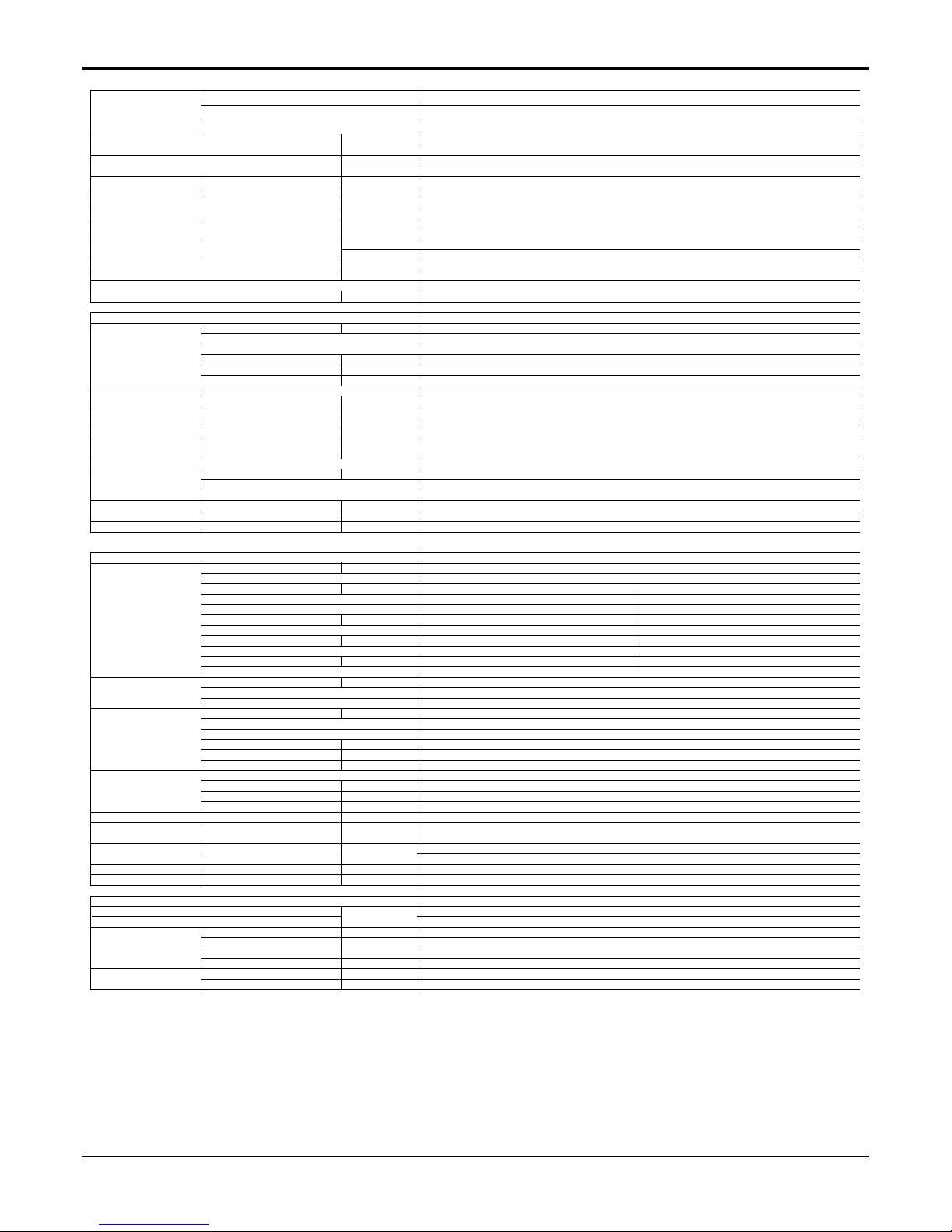
Notes: 1. Capacities are based on the following conditions:
Cooling: - Indoor Temperature 26.7°C(80.0°F) DB /19.4°C(67.0°F) WB
- Outdoor Temperature 35.0°C(95.0°F) DB /23.9°C(75.0°F) WB
- Interconnecting Piping Length 7.5m
- Level Difference of Zero.
2. Due to our policy of innovation some specifications may be changed without notification.
16 Ceiling Cassette Air Conditioner
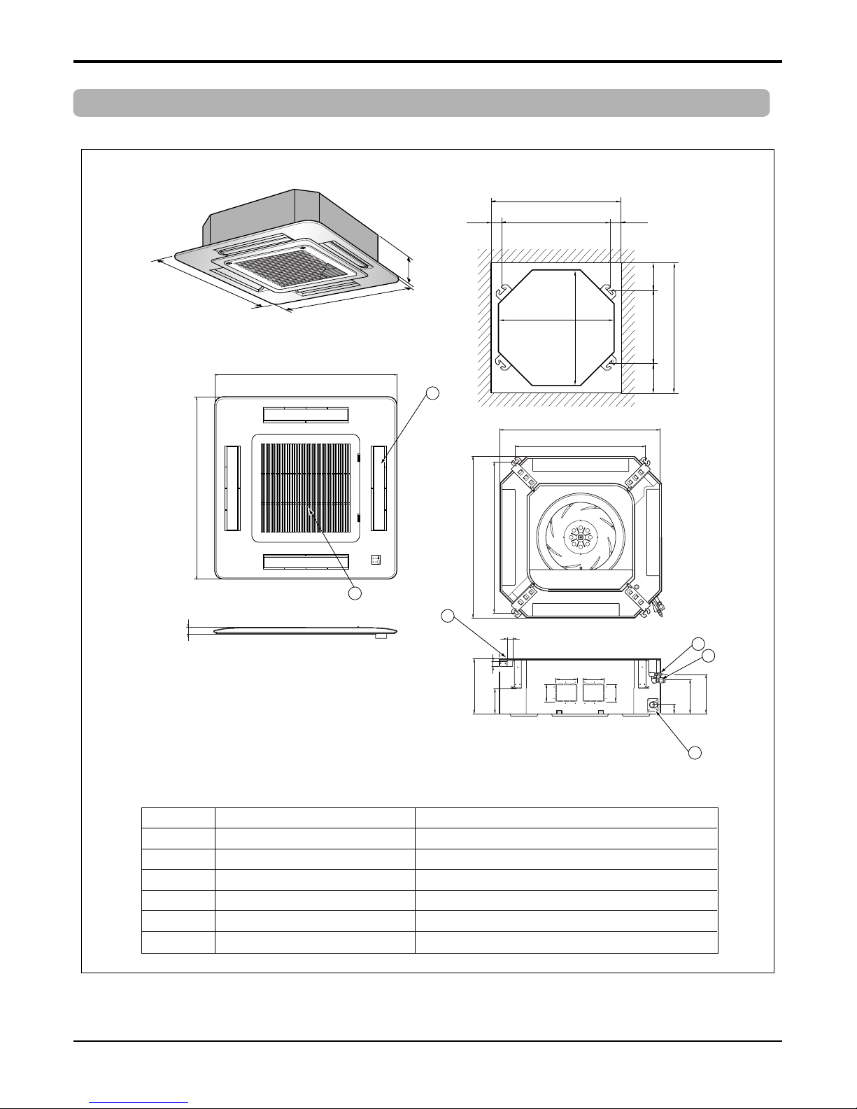
292
292
212
150
54
90
90
192 117
70
110 110
850
850
850
850
744
658
572
744
Unit:mm
744 Unit size
744 Unit size
658 (Hanging bolt)
6666
790 (Ceiling opening)
790 (Ceiling opening)
572(Hanging bolt)
109
109
30
5
6
4
1
2
3
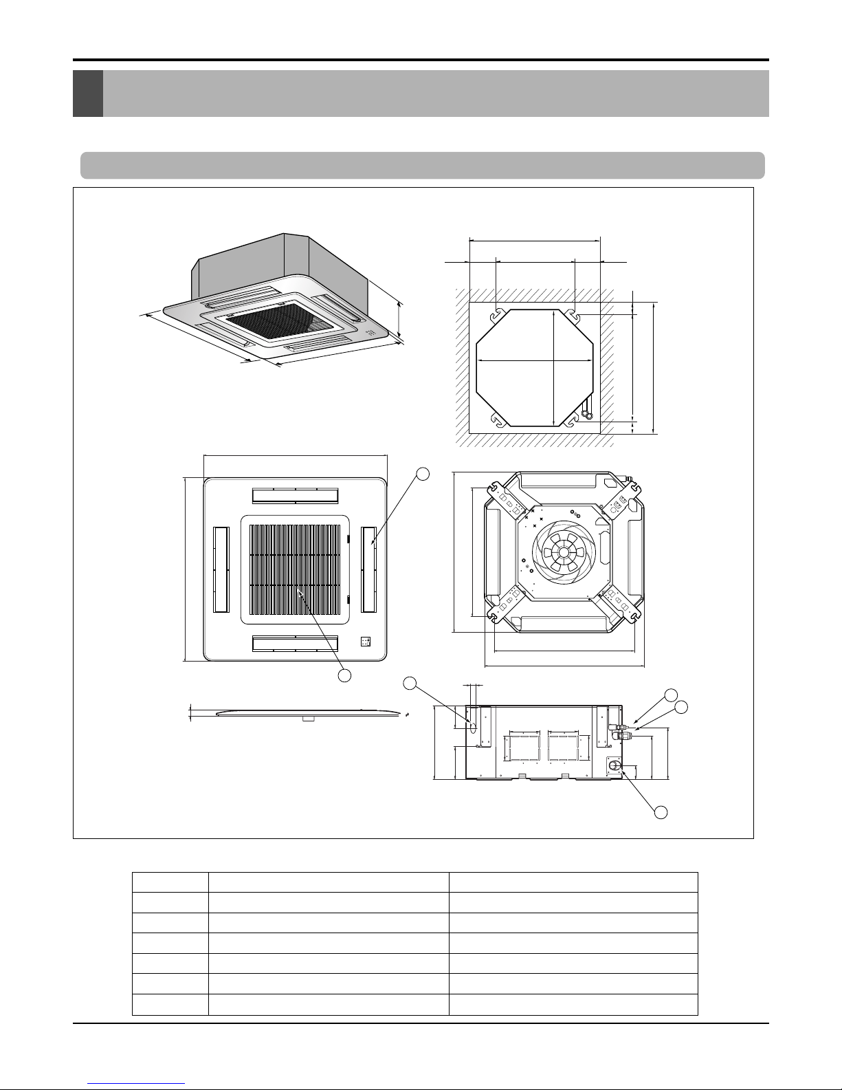
Number Name Descripition
1 Liquid pipe connection Ø6.35 flare (1/4")
2 Gas pipe connection Ø12.7 flare (1/2")
3 Drain pipe connection
4 Power supply connection
5 Air discharge grill
6 Air suction grill
(unit : mm)
Dimensional Drawings
1. Indoor Units
Model No.: LCN240CP
Dimensional Drawings
Service Manual 17
Dimensional Drawings
288
950
950
290
210.5
180
52
140
40
110
30
90
90
110
30
840
785
840
678
840 Unit size
840 Unit size
672 (Hanging bolt)
101.5101.5
875 (Ceiling opening)
875 (Ceiling opening)
785(Hanging bolt)
45
45
Unit:mm
4
1
2
3
950
950
5
6
Number Name Descripition
1 Liquid pipe connection Ø6.35 flare (1/4")
2 Gas pipe connection Ø15.88 flare (5/8")
3 Drain pipe connection
4 Power supply connection
5 Air discharge grill
6 Air suction grill
(unit : mm)
Model No.: LCN380CP
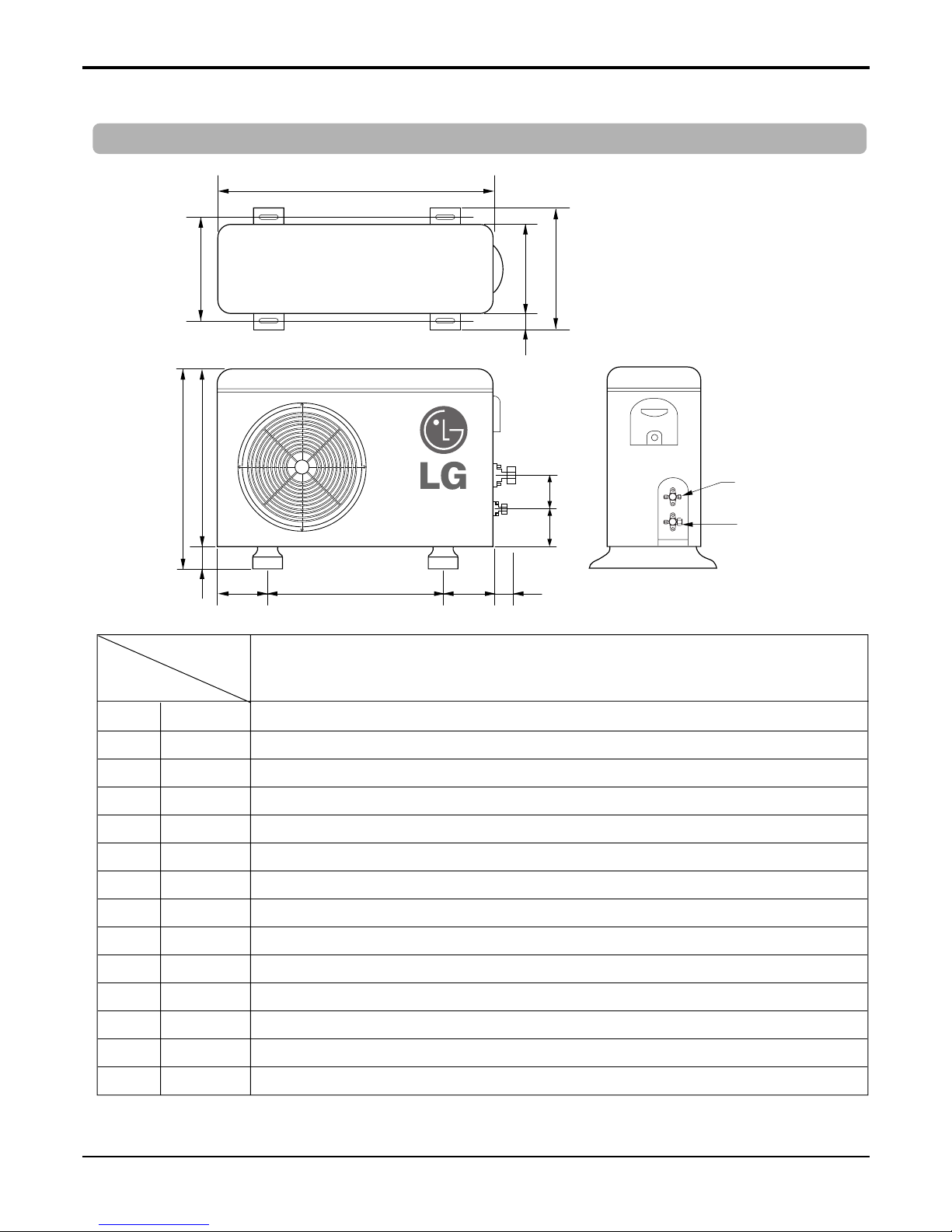
Model No.
Dim
W mm 870
H mm 800
D mm 320
L1 mm 370
L2 mm 25
L3 mm 340
L4 mm 775
L5 mm 25
L6 mm 546
L7 mm 162
L8 mm 162
L9 mm 54
L10 mm 74.5
L11 mm 79
LCU240CP
Gas side
3-way valve
Liquid side
3-way valve
W
D
L1
L2
L3
L6L7 L8 L9
L4
H
L11
L10
L5
18 Ceiling Cassette Air Conditioner
Dimensional Drawings
Model No.: LCU240CP
2. Outdoor Units
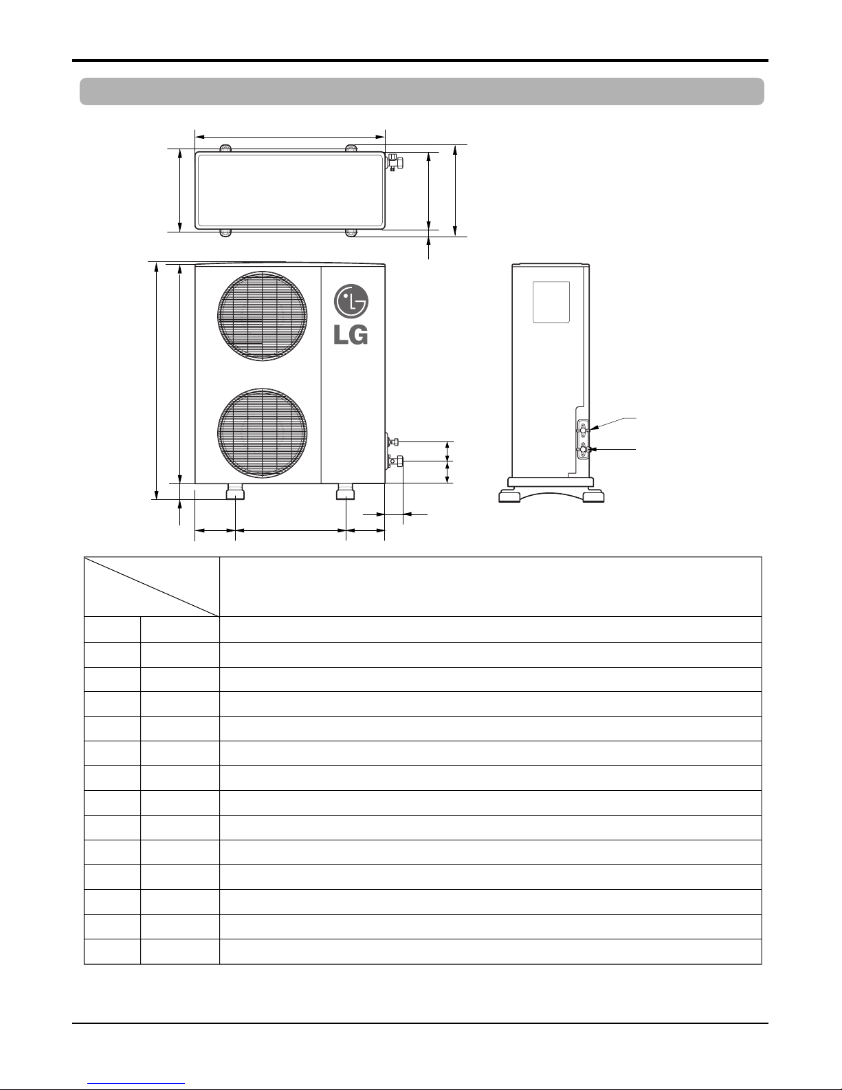
Service Manual 19
Dimensional Drawings
Model No.: LCU380CP
Model No.
Dim
W mm 900
H mm 1,225
D mm 370
L1 mm 460
L2 mm 45
L3 mm 410
L4 mm 1,135
L5 mm 90
L6 mm 550
L7 mm 175
L8 mm 175
L9 mm 112
L10 mm 120
L11 mm 83
LCU380CP
L6L7 L8
L9
L4
H
L11
L10
L5
W
D
L1
L2
L3
Gas side
3-way valve
Liquid side
3-way valve
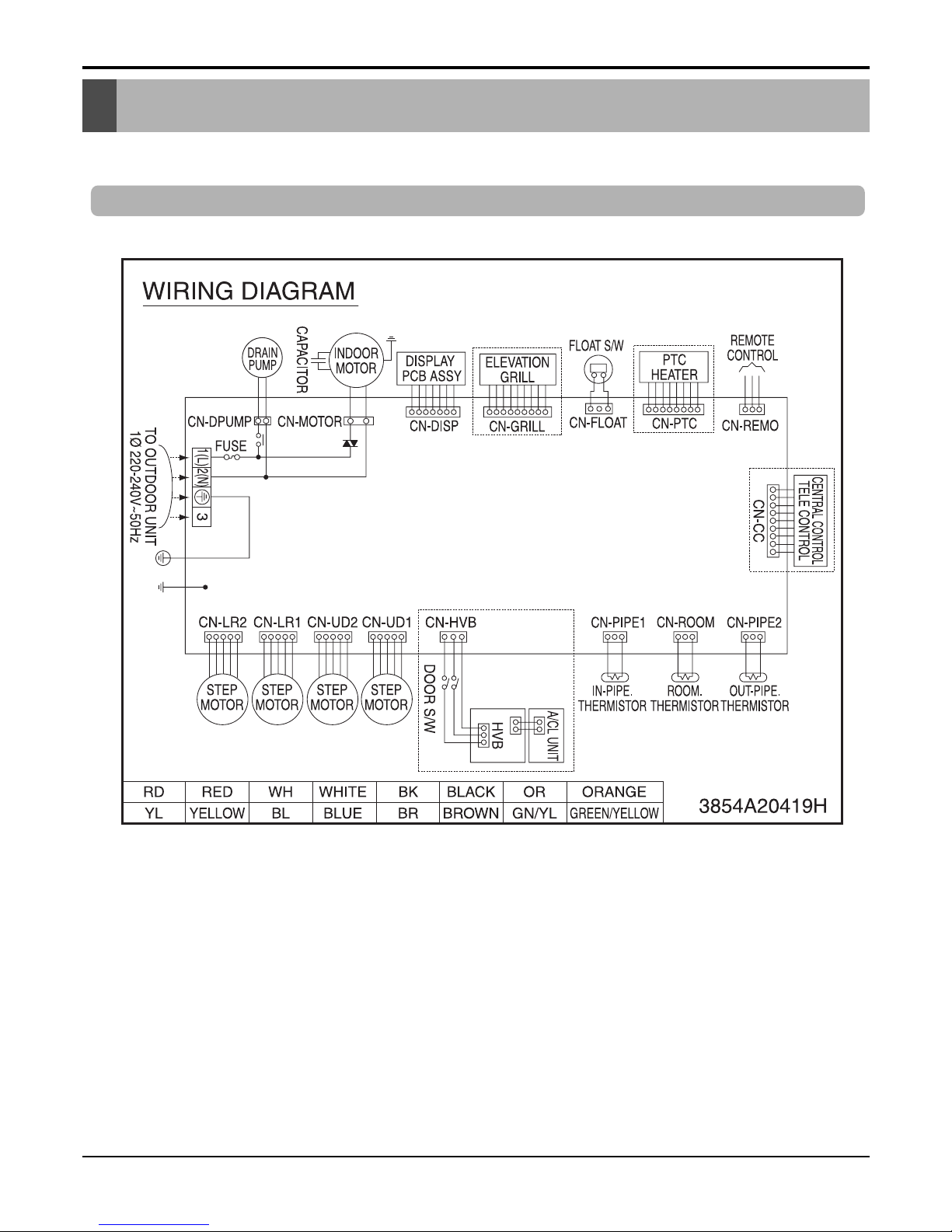
20 Ceiling Cassette Air Conditioner
Wiring Diagrams
1. Indoor Unit
LCN240CP
Wiring Diagrams
 Loading...