

LG LCP2850-AP Owner’s Manual

OWNER’S MANUAL
Dome
ENGLISH
Camera
Please read this manual carefully before operating
your set and retain it for future reference.
MODEL
LCP2850-AN/AP
LCP2850I-AN/AP

1
Safety Information
Warning: Do not install this equipment in a confined
CAUTION
RISK OF ELECTRIC SHOCK
DO NOT OPEN
CAUTION: TO REDUCE THE RISK OF ELECTRIC SHOCK
DO NOT REMOVE COVER (OR BACK)
NO USER-SERVICEABLE PARTS INSIDE
REFER SERVICING TO QUALIFIED SERVICE PERSONNEL.
This lightning flash with arrowhead symbol
within an equilateral triangle is intended to
alert the user to the presence of uninsulated
dangerous voltage within the product’s
enclosure that may be of sufficient magnitude
to constitute a risk of electric shock to persons.
The exclamation point within an equilateral
triangle is intended to alert the user to
the presence of important operating and
maintenance (servicing) instructions in the
literature accompanying the product.
space such as a bookcase or similar unit.
Warning: Wiring methods shall be in accordance with the
National Electric Code, ANSI/NFPA 70.
Warning: This is a class A product. In a domestic
environment this product may cause radio interference
in which case the user may be required to take adequate
measures.
Warning: To reduce a risk of fire or electric shock, do not
expose this product to rain or moisture.
Caution: This installation should be made by a qu alified
service person and should conform to all local codes.
Caution: To avoid electrical shock, do not open the
cabinet. Refer servicing to qualified personnel only.
Caution: The apparatus should not be exposed to water
(dripping or splashing) and no objects filled with liquids,
such as vases, should be placed on the apparatus.
Safety Information
3
1
Safety Information
This Class A digital apparatus complies with Canadian
ICES-003.
Cet appareil numérique de la classe A est conforme à la
norme NMB-003 du Canada.

Safety Information
4
1
Safety Information
LG Electronics hereby declares that this/
these product(s) is/are in compliance
with the essential requirements and
other relevant provisions of Directive
2004/108/EC and 2011/65/EU.
Contact oce for compliance of this
product:
LG Electronics Inc.
EU Representative, Krijgsman 1,1186
DM Amstelveen, The Netherlands
Safety Precautions
• Do not attempt to disassemble the camera
To prevent electric shock, do not remove screws or
covers. There are no user serviceable parts inside. Ask a
qualified service personnel for servicing.
• Avoid the camera with direct sunlight
Do not aim the camera at bright objects.Whether the
camera is in use or not, never face it with direct sunlight
or other extremely bright objects. Otherwise blooming
or smear may be caused.
• Handle the camera with care
Do not abuse the camera. Avoid striking, shaking, etc.
The camera could be damaged by improper handling
or storage.
• Do not use strong solvents or detergents
Use a dry cloth to the camera when it is dirty. If it is
hard to remove the dirt on the camera, use a mild
detergent and wipe it gently.
• Do not install this camera upside down
This camera is designed for mounting on the ceiling or
wall.If you install this camera upside down, for example,
mounted on the floor, it may cause malfunction.
• Do not use the camera in such places as shown below.
The lens may become cloudy due to condensation if
the camera is used under the following conditions.
› Rapid temperature fluctuation by switching an air
conditioner on and off.
› Rapid temperature fluctuation due to frequent
door opening and closing.
› Use in an environment where eyeglasses become
foggy.
› Use in a room filled with cigarette smoke or dust.
If the lens becomes cloudy due to condensation,
remove the dome cover and wipe all moist surfaces
with a soft cloth.
• Before operating, please check proper temperature,
humidity and power source ratings.
Use the camera under conditions where temperature
is from -20 °C to 50 °C and humidity is below 80 %. The
input power source is AC 24 V.

Safety Information
5
• Consumables
Parts having contacts such as the lens-drive motors,
cooling fan built inside the camera are subject to wear
with time. About replacement and maintenance of
such parts, please ask the nearest service center.
Camera Installation Location
Discuss the installation location for the camera with your
retailer, and select a place that is strong enough
for the installation.
• Install the camera on a ceiling (concrete, etc.) at a
location that is sufficiently strong to support it.
• Install the camera body on the foundation section
of the building or sections having sufficient bearing
strength.
Never install or use the camera in the following
locations
• Do not install it in areas exposed to direct sunlight or
rain.
• Do not install the camera near the air outlet of an air
conditioner.
• Near a swimming pool or other areas where chemicals
are used.
• Food preparation areas and other locations where there
are large amounts of steam vapor and oil, in flammable
atmospheres, other special environments.
• Areas where radiation, X-rays, strong electric waves, or
magnetism is generated.
• At sea, in coastal areas, or in areas where corrosive gas
is being generated.
• Areas outside of the allowable ambient operating
temperature range.
About Static Electricity Removal
Before installing the camera, touch a metal case or other
metallic parts with your hand to remove static electricity
from your body.
Do not install in areas subjected to high amounts of
humidity or dust.
Doing so may cause internal components to damage more
easily or malfunction.
Do not wire cables near power lines.
Tightening the Screws
Screws should be tightened sufficiently in accordance with
the materials and structure of the installation location. After
tightening the screws, visually inspect them to make sure
there is no unevenness and that each screw is tight.
1
Safety Information

Contents
6
Contents
1
Safety Information
4 Safety Precautions
19 Connecting power source
19 Protocol and baud rate settings
20 Camera ID Setting
23 Removing the Protection Tape
24 Mounting the camera
24 Surface mount (optional)
25 Ceiling mount (optional)
27 Wall mount (optional)
29 Pendant mount (Optional)
4
2
Preparation
8 Introduction
8 Features
9 Accessories
10 Part Names and Functions
3
Installation
12 Connections
12 Precautions
12 Basic Connection Overview
13 Connecting Display device
13 ALARM input connection
15 ALARM output connections
17 Connecting LKD1000 controller
17 Connecting RS-485 device
Operation
33 Setup Menu Overview
37 Menu navigation
37 Accessing the camera setup menu
37 General operation
38 Camera menu settings
38 Focus setting
38 Exposure settings
39 White Balance setting
40 Day/Night setting
40 3D-DNR setting
41 Color setting
41 Sharpness setting
41 Stabilizer setting
41 PAN/TILT Settings
41 Preset setting
43 Group tour setting
43 Pattern setting

44 Auto Pan setting
44 Privacy Mask setting
Contents
7
45 Special setting
47 OSD Settings
47 User title setting
47 ZOOM MAG setting
47 FUNCTION setting
48 DOME ID setting
48 LANGUAGE Setting
48 ALARM Setting
48 Alarm In setting
49 Alarm Out setting
49 RESET Setting
49 Information
49 Initialization
49 Camera reset
49 Factory reset
1
2
3
4
5
5
Appendix
50 Specifications
8
Preparation
2
Preparation
2
Introduction
Preparation
The dome cameras are designed for installation in an
indoor or outdoor video surveillance system.
The camera incorporates the digital signal processor, pan/
tilt mechanism, zoom lens and RS-485 communication
interface in a compact outdoor enclosure.
Features
• High Sensitivity Support
The camera provides the high quality picture with
4.5 mm (1/4 Type) Super HAD II CCD.
• Preset Position
Preset position is the function to register camera
monitoring positions (preset positions). By using
LKD1000 controller, you can register presets with
position number. Maximum 256 Preset Positions are
available. By entering the position numbers, you can
move cameras to the preset positions. The moving
speed and holding time are adjustable.
• Preset Tour
Preset Tour is the function to go through all the
registered camera monitoring positions (preset
positions). During the working PRESET TOUR, The
FOCUS could not be operated properly under -20 °C .
• Group Tour
Maximum 10 group tours are able to compose the
group of preset, pattern, auto pan that the operator
can program to be linked together in a sequence.
• Pattern recording function
A routine of manual operations can be stored and
reproduced repeatedly. The Pan, Tilt and Zoom controls
are available for pattern recording.
Note
,
The available total time of pattern diers depending
on camera’s operation. When the pattern recording is
full, the pattern recording will automatically stop.
• Privacy Mask
Privacy zone feature enables users to veil unwanted
zones. This setting is used for masking unwanted zones,
hiding them from display on the monitor screen. Up to
8 zones can be registered.
• Auto Pan
The camera has an Auto Pan function that enables to
keep surveillance on every detail occurring around the
specic area, which is preset to watch in advance. The
camera can pan among the maximum 8 points you will
set. The moving speed and holding time are adjustable.
• Auto Flip
When the camera is operated to tilt through the 90°, it
can be watched the opposite side of the locations by
Auto Flip of a 180° horizontally.
• Optical Zoom
- The optical zoom range is 1x to 28x.
• Digital Zoom
Digital zoom enhances the systems zoom range to 12
times beyond the optical zoom limit.
Total system zoom range is below.
- 28x (1x digital zoom) to 336x (12x digital zoom)
• Alarm In function (4 channels)
Alarm input signals are supplied from external devices
through the ALARM IN connector to activate ‘go to
preset’ function.
• Alarm Out function (2 channels)
When alarm inputs are supplied via the alarm input
connector on the camera, the camera sends output
signals via the alarm output connector on the camera.
Preparation
9
• Controls by General Controller
This camera can be controlled by RS-485. Especially the
camera has an excellent cost-saving eect because it
can be controlled by the general RX point of contact
signal.
• Connects with the maximum 256 cameras
This camera can be utilized after being connected
with maximum 256 cameras. Therefore, it is capable of
performing an excellent job in the large buildings or
department stores.
• Day & Night Function
This camera can be selected Color or Black & White. You
can set Color in the daytime and Black & White at night
due to the low illumination. (Filter Conversion type)
• DSS (Digital Slow Shutter) function
It is possible to highly sensitive surveillance because of
DSS(Digital Slow Shutter) function.
• WDR (Wide Dynamic Range) function
The camera can be best condition to watch easily
inside or outside in the strong back light.
• Power Supply
This camera must always be operated a AC 24 V.
Certified/Listed Adaptor which comply with LPS.
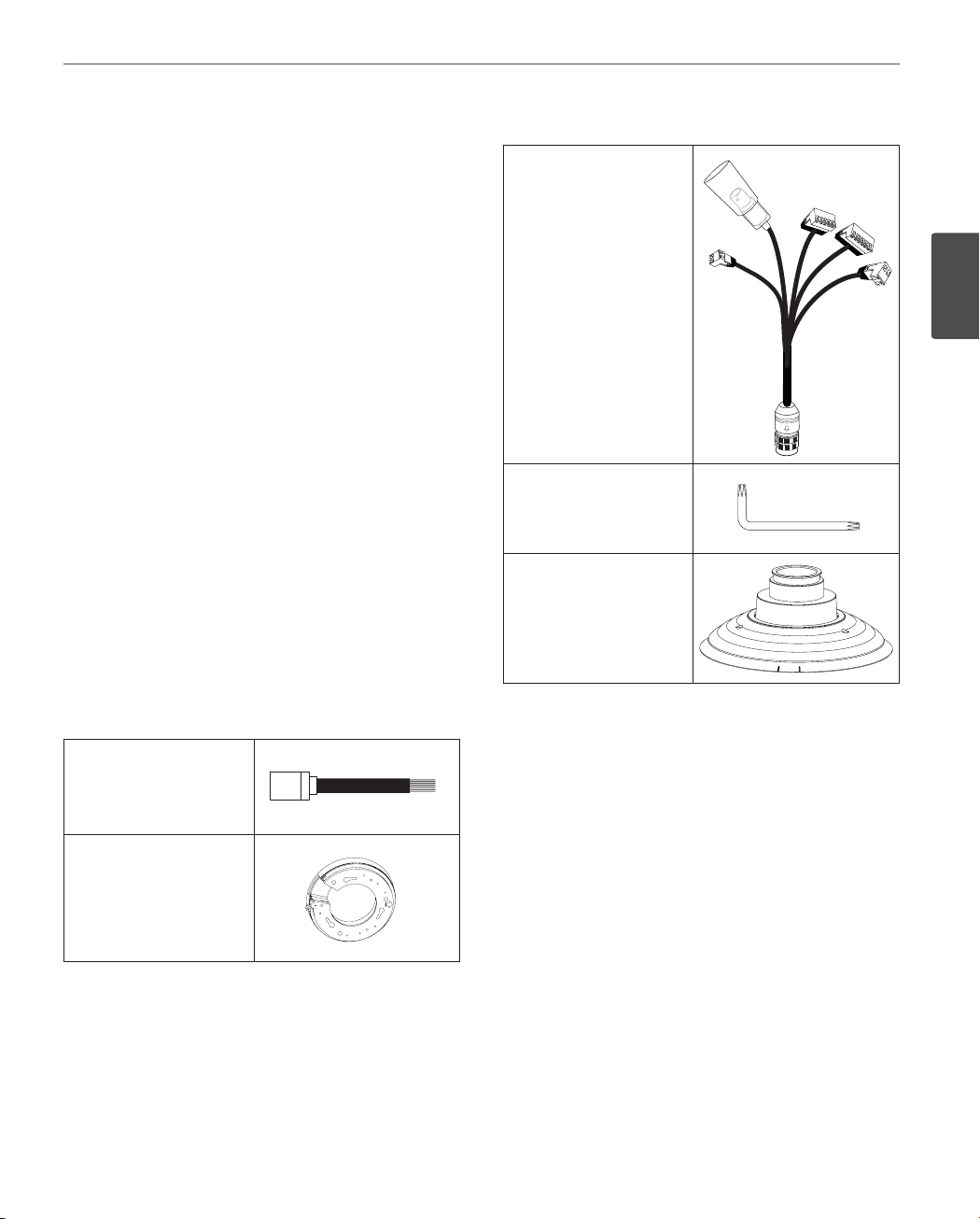
For LCP2850-AN/AP
Camera main cable
2
Preparation
Wrench
PIPE Installation Bracket
Accessories
For LCP2850I-AN/AP
RJ-45 Adapter cable
Camera mounting
bracket
10
Preparation
Part Names and Functions
LCP2850I-AN/AP for Indoor
2
Preparation
a
b
c
d
e
f
g
h
i
a BNC connector cover cap
b Video output BNC connector
Supplies analog video signal (composite) to the
connected device.
c Data Port A (RJ-45)
RS-485 data communication and input data port
for alarm (relay) signal.
d Data Port B (RJ-45)
Output data port for alarm (relay) signal.
e
This port is not used.
f
This port is not used.
g
Power input jack
Connects to a AC 24 V power supply using proper
cables.
h This port is not used.
i
Locking screw
Tighten this screw to fixing the Ceiling Mount
Assembly with camera body.
j Dome Cover open button.
k Dome Cover
j
k
Preparation
11
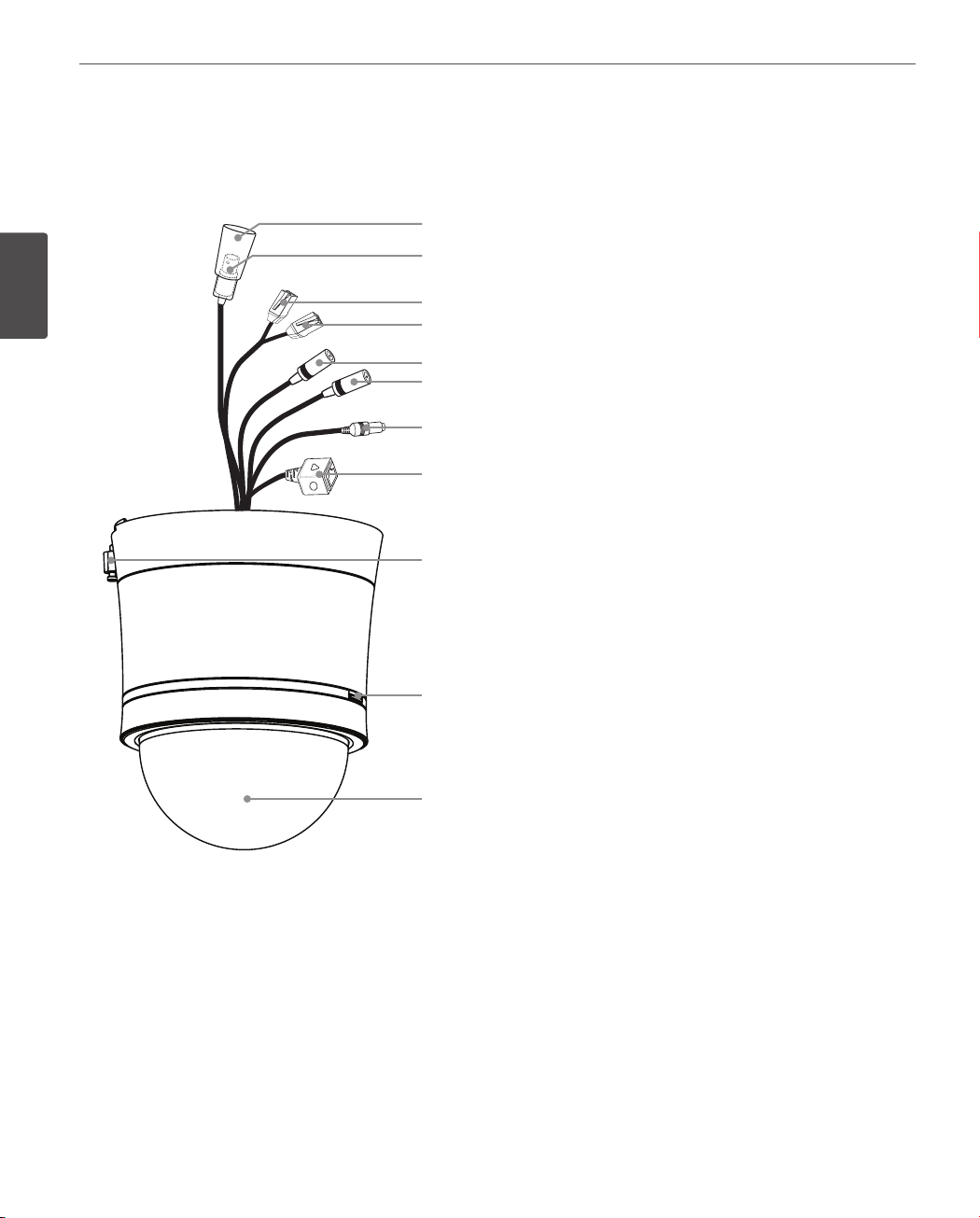
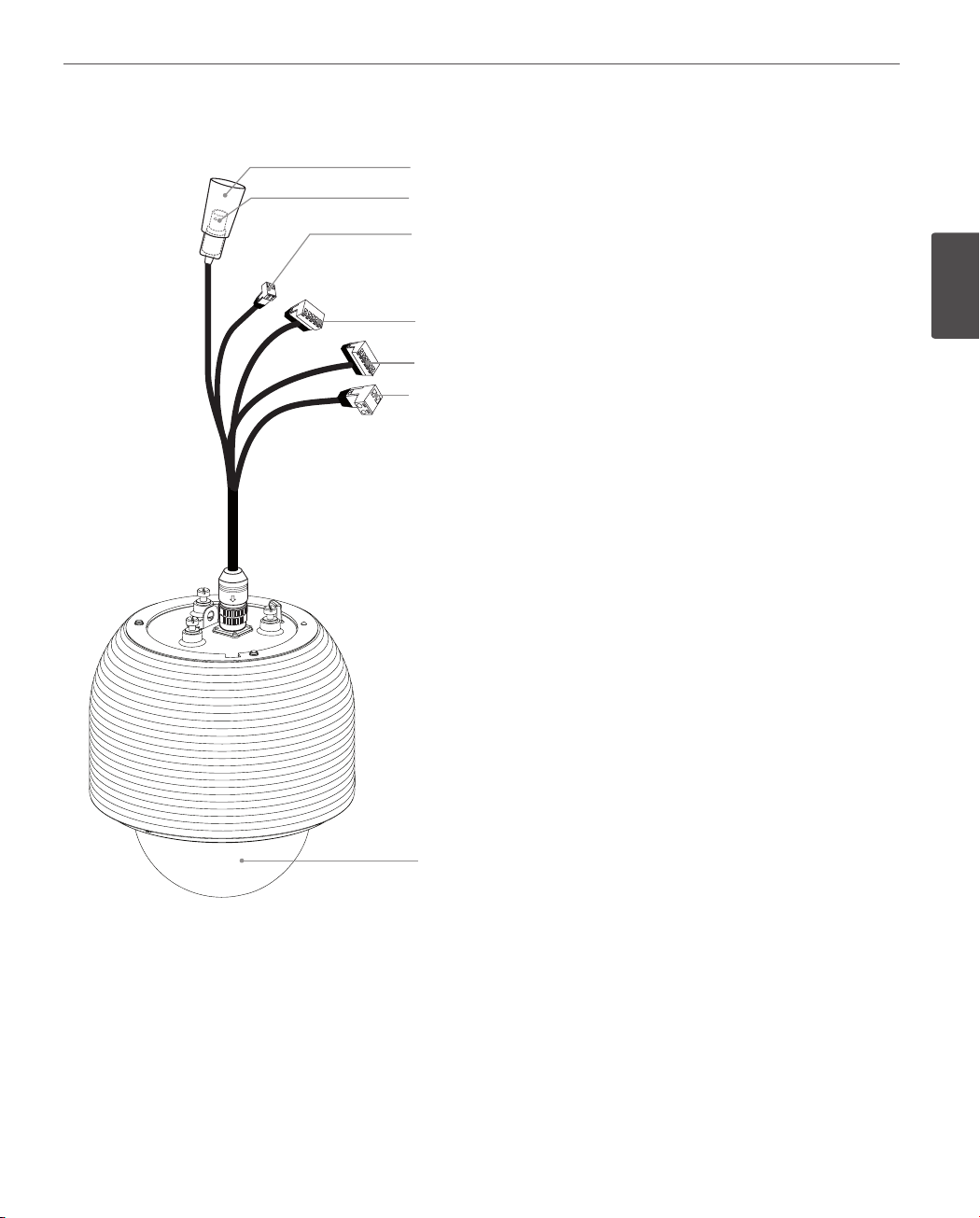
LCP2850-AN/AP for Outdoor
a
b
c
d
e
f
a BNC connector cover cap
b Video output BNC connector
Supplies analog video signal (composite) to the
connected device.
c RS-485 Data Communication
d Alarm In Data Terminal
Input data terminal for alarm (relay) signal.
e
Alarm Out Data Terminal
Output data terminal for alarm (relay) signal.
f
Power input Terminal
Connects to a AC 24 V power supply using proper
cables.
g
Dome Cover
2
Preparation
g
Installation
12
3
Installation
Connections
Precautions
3
• The following steps of installation and connection work should be done by qualified service personnel or system
Installation
installers and should conform to all local codes.
• Before you install and connect the camera, check and prepare the required peripheral devices and cables.
• Before you connect the camera, turn off all devices to be connected, such as this camera and DVR.
• Do not touch the dome cover’s window.
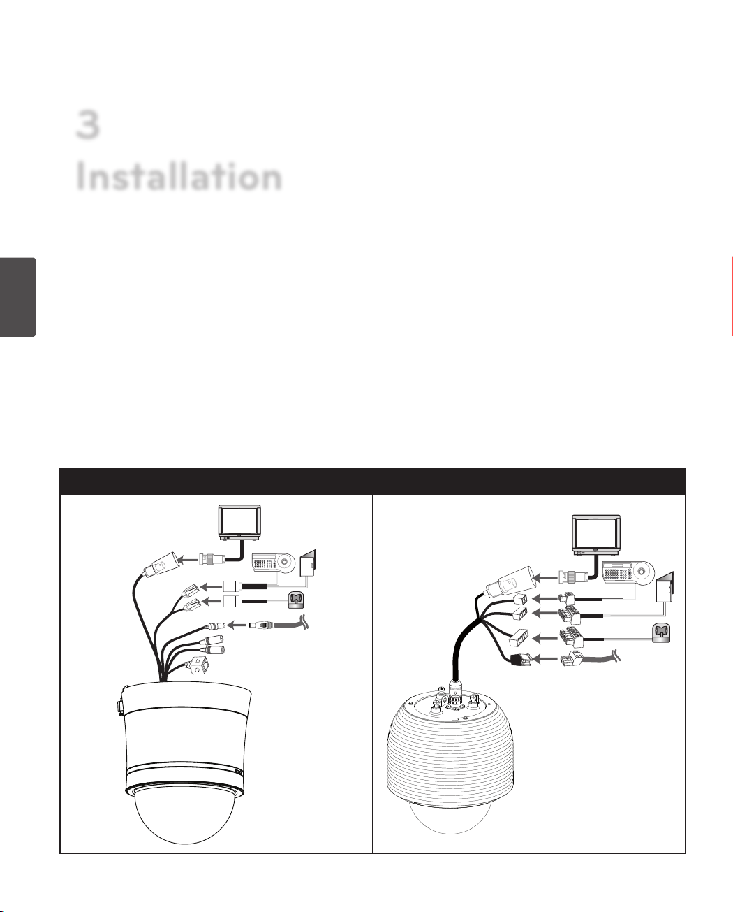
Basic Connection Overview
LCP2850I-AN/AP (for Indoor) LCP2850-AN/AP (for outdoor)
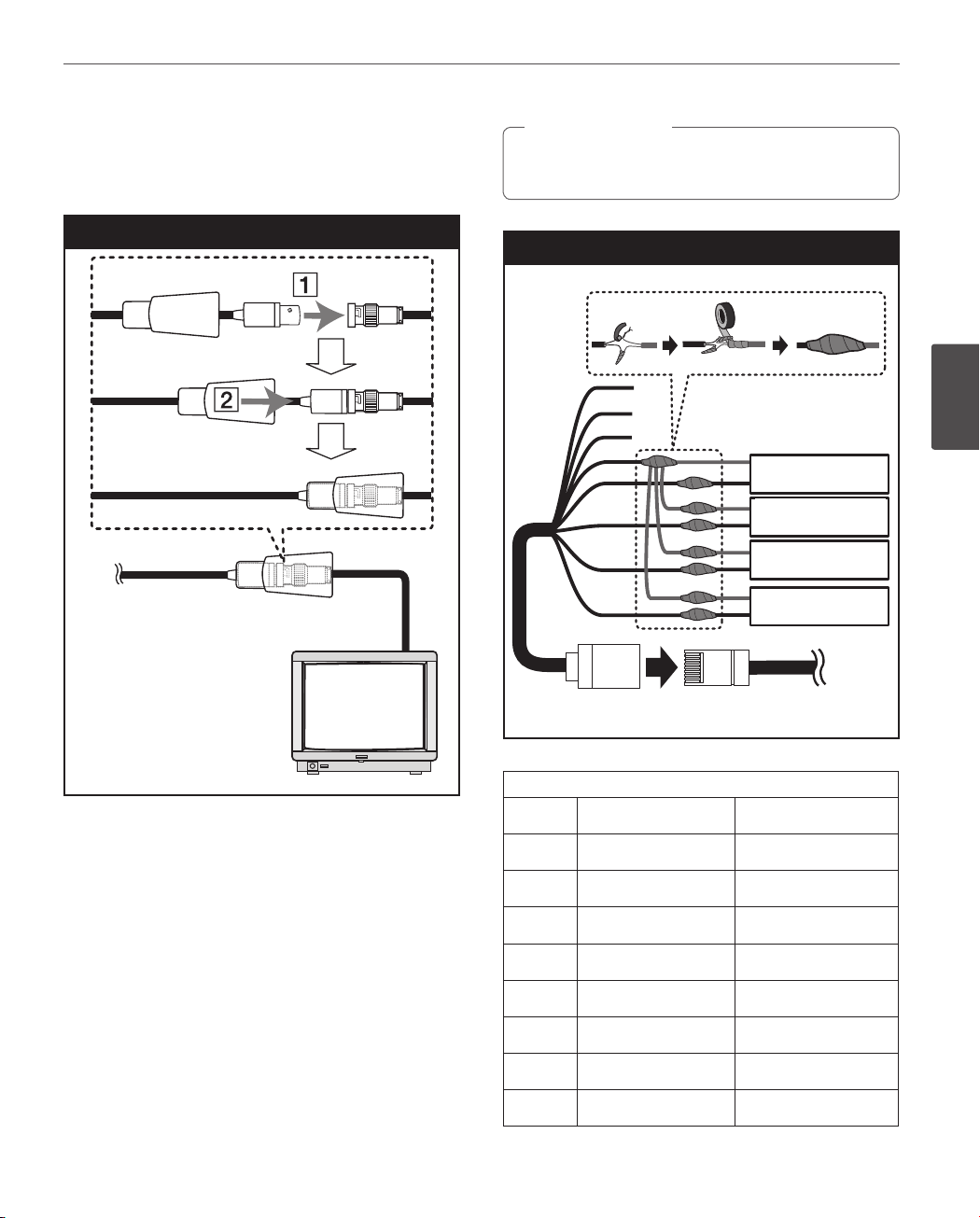
Connecting Display device
The video signal connection between the camera and the
monitor.
Installation
Caution
>
Do not connect one alarm sensor to the several
camera’s alarm input connector.
13
Display device connection
Alarm input connection
A
B
C
D
E
F
G
H
RJ-45 Adaptor cable
PORT ARJ-45 Adapter cable
PORT A
Alarm device
Alarm device
Alarm device
Alarm device
Alarm device
Alarm device
Alarm device
Alarm device
3
Installation
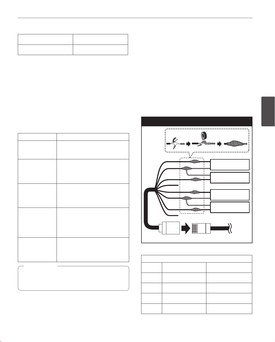
ALARM input connection
You can connect up to 4 alarm sensors to the camera. Each
alarm sensor should be connected with Alarm IN COM. You
can adjust the signal state to NO (normally open) or NC
(normally closed) through the setup menu.
For LCP2850I-AN/AP
1. Connect the RJ-45 Adaptor cable to the PORT A (RJ-45)
cable of the camera.
2. Connect the alarm device to the RJ-45 Adaptor cable.
When connecting lines, check and connect the color
lines of the each device correctly. Refer to the below
tables for color line information.
RJ-45 Adaptor cable
No Description Color
A
B
C
D
E
F
G
H
RS-485 + White
RS-485 - Orange
NC Black
ALARM IN COM Red
ALARM IN 1 Green
ALARM IN 2 Yellow
ALARM IN 3 Blue
ALARM IN 4 Brown
14
Installation
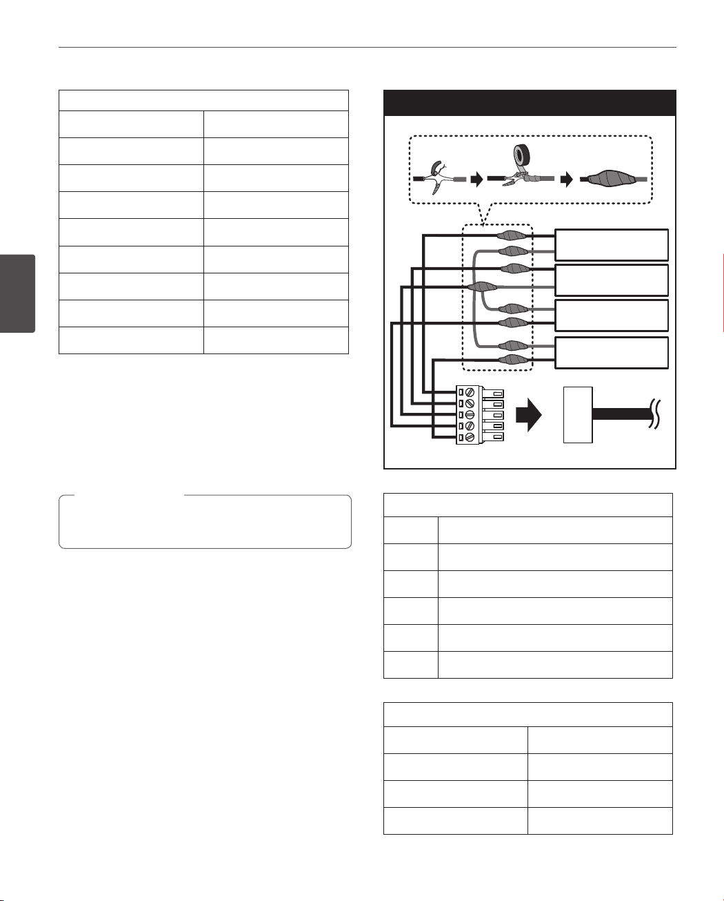
PORT A
Description Color
RS-485 + Red/White
RS-485 - Black/White
NC
ALARM IN COM Red
ALARM IN 1
ALARM IN 2
3
Installation
ALARM IN 3 Yellow
ALARM IN 4 Pink
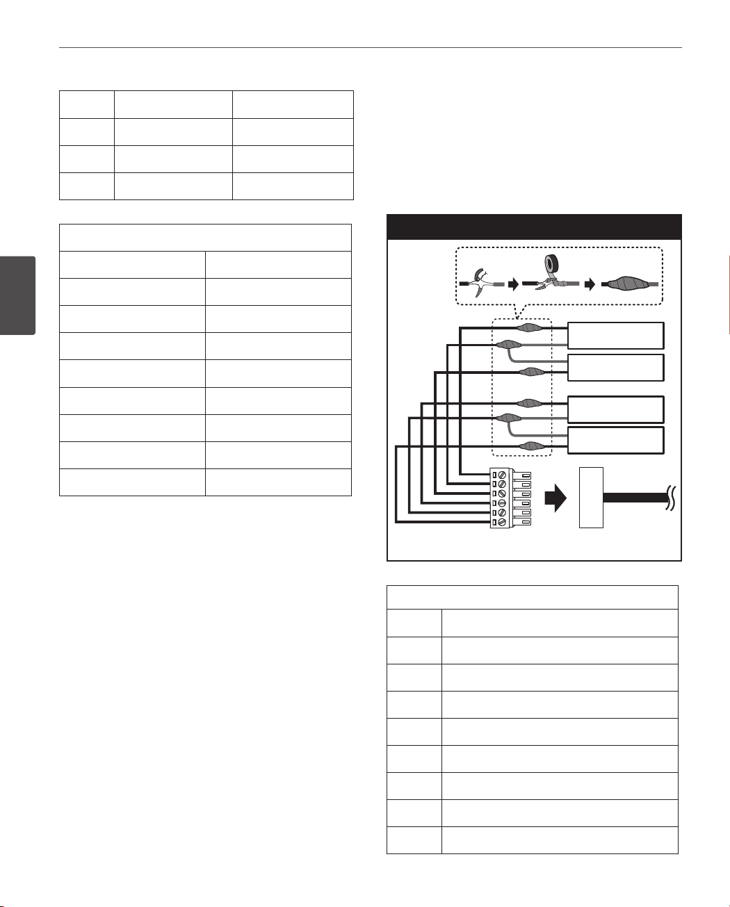
For LCP2850-AN/AP
1. Connect the Adaptor cable to the Alarm In Data
Terminal of the camera.
2. Connect the alarm device to the Adaptor cable.
When connecting lines, check and connect the color
lines of the each device correctly. Refer to the below
tables for color line information.
Caution
>
Do not connect one alarm sensor to the several
camera’s alarm input connector.
White
Light Green
Alarm input connection
A
B
C
D
E
Adaptor Cable
Adaptor cable
No
Alarm device
Alarm device
Alarm device
Alarm device
Alarm In Data Terminal
Description
A
B
C
D
E
Alarm In Data Terminal
Description Color
ALARM IN 1 Pink
ALARM IN 2 Gray
ALARM IN COM Yellow
ALARM IN 1
ALARM IN 2
ALARM IN COM
ALARM IN 3
ALARM IN 4
Installation
15
ALARM IN 3 White
ALARM IN 4 Violet
Alarm Input function
This speed dome camera has a terminal that can sense the
alarm signals.
If the alarm sensor that has installed in a door, window,
safe etc. sense a touch or shock, the alarm sensor send the
alarm signal to the camera and the camera will observe the
sensed position.
Change the observe position to a sensor that senses a
touch or shock then return to the position that previously
observed. (Set the Duration Time of Alarm Input function
to “3 to 255”.)
Function status Mode
While observe a
specific position.
While operating
Preset Tour
function.
While operating
Auto Pan function.
While operating
Pattern function.
in case of HOME
POSITION is ON.
Note
,
Do not connect one alarm sensor to the several
camera’s alarm input connector.
Change the observe position to the
alarmed position then return to the
position that previously observed.
Stop preset touring and change the
observe position to the alarmed
position then restart the preset
touring again.
Stop auto panning and change the
observe position to the alarmed
position then restart the auto
panning again.
Stop operating pattern function
and change the observe position
to the alarmed position during the
dwell time then restart the pattern
function again.
After Alarm has been cleared and
finished the dwell time, it moves to
the HOME POSITION and spend the
dwell time at that position.
ALARM output connections
Connect the alarm device to the alarm output data port.
Alarm signal output at an event occurrence. You can set the
Alarm Output to the normal open or normal close mode.
For LCP2850I-AN/AP
1. Connect the RJ-45 Adaptor cable to the PORT B (RJ-45)
cable of the camera.
2. Connect the alarm device to the RJ-45 Adaptor cable.
When connecting lines, check and connect the color
lines of the each device correctly. Refer to the below
tables for color line information.
Alarm Out connection
A
B
C
D
E
F
G
H
PORT BRJ-45 Adapter cable
RJ-45 Adaptor cable
PORT B
RJ-45 Adaptor cable
No Description Color
A
B
ALARM OUT [NO1]
ALARM OUT [COM1] Orange
Alarm device
Alarm device
Alarm device
Alarm device
Alarm device
Alarm device
Alarm device
Alarm device
White
3
Installation
C
D
ALARM OUT [NC1] Black
NC Red
16
Installation
3
Installation
E
F
G
H
ALARM OUT [NO2] Green
ALARM OUT [COM2] Yellow
ALARM OUT [NC2] Blue
NC Brown
PORT B
Description Color
ALARM OUT [NC1] Blue
ALARM OUT [COM1] Violet
ALARM OUT [NO1] Brown
NC
ALARM OUT [NC2] Gray
ALARM OUT [COM2]
ALARM OUT [NO2] Black
NC
Orange
For LCP2850-AN/AP
1. Connect the Adaptor cable to the Alarm Out Data
Terminal of the camera.
2. Connect the alarm device to the Adaptor cable.
When connecting lines, check and connect the color
lines of the each device correctly. Refer to the below
tables for color line information.
Alarm Out connection
A
B
C
D
E
F
Alarm device
Alarm device
Alarm device
Alarm device
Alarm device
Alarm device
Alarm device
Alarm device
Adaptor Cable
Alarm Out Data Terminal
Adaptor cable
No Description
A
B
C
ALARM OUT [NO1]
ALARM OUT [COM1]
ALARM OUT [NC1]
D
E
F
G
ALARM OUT [NO2]
ALARM OUT [COM2]
ALARM OUT [NC2]
H
NC
NC
 Loading...