

Page 1

LG
Ceiling Cassette
Air Conditioner
SERVICE MANUAL
LG
CAUTION
website http://www.lgservice.com
e-mail http://www.lgeservice.com/techsup.html
• BEFORE SERVICING THE UNIT, READ THE SAFETY
PRECAUTIONS IN THIS MANUAL.
• ONLY FOR AUTHORIZED SERVICE PERSONNEL.
MODEL: LCN240CP/LCU240CP
LC240CPI/LC240CPO
LCN340CP/LCU340CP
LC340CPI/LC340CPO
Page 2

2 Ceiling Cassette Air Conditioner
TABLE OF CONTENTS
Table of contents Page
1. Models List .......................................................................................................................3
2. Safety Precautions ...........................................................................................................4
3. Feature & Benefits ...........................................................................................................8
4. List of Functions .............................................................................................................11
5. Function of Remote Control ...........................................................................................12
6. Specifications .................................................................................................................14
7. Dimensional Drawings ...................................................................................................16
8. Wiring Diagrams.............................................................................................................19
9. Refrigerant Cycle Diagrams ...........................................................................................21
10. Installation ....................................................................................................................22
11. Trouble Shooting Guide................................................................................................32
12. (3-Way)Valve ................................................................................................................48
13. Electronic Control Device.............................................................................................52
14. Exploded View and Replacement Parts List ................................................................53
Page 3
Models List
Service Manual 3
Models List
❈ Local model name
1.2 Outdoor units
1. Model line up
1.1 Indoor units
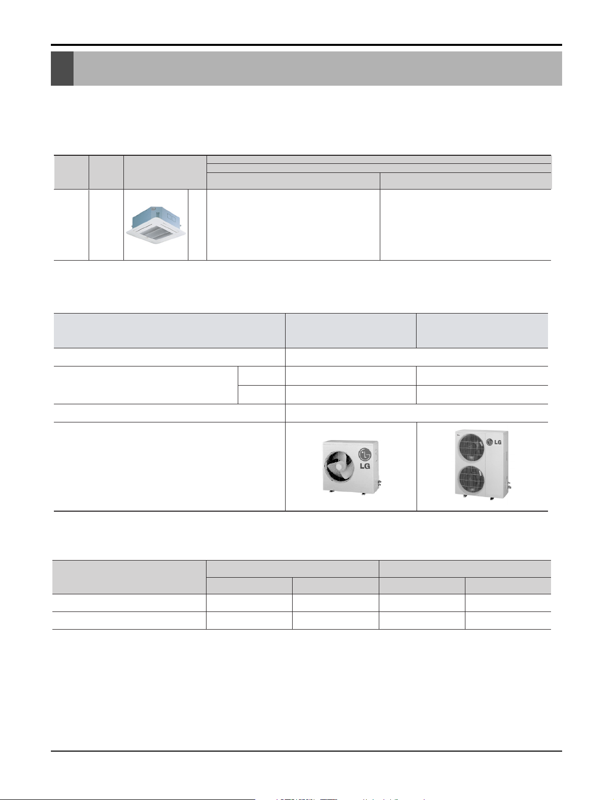
Category Type
Chassis
Model names
Capacity, kW(kBtu/h)
7.03(24) 9.96(34)
Ceiling
cassette
4-way
Cooling only
Total capacity index of connectable
indoor units
Chassis
TH
AT-C243HLF0 AT-C343HLF0
AT-C243HLF0 AT-C343HLF0
1No. of connectable indoor units
9.967.03kW
3424kBtu/h
1Ø, 208-230V, 60HzPower supply
Factory
AT-C243HLF0
AT-C343HLF0
Local Model 1
Indoor Outdoor Indoor Outdoor
LCN240CP
LCN340CP
LCU240CP
LCU340CP
LC240CPI
LC340CPI
Local Model 2
LC240CPO
LC340CPO
Page 4
4 Ceiling Cassette Air Conditioner
Safety Precautions
To prevent injury to the user or other people and property damage, the following instructions must
be followed.
■ Incorrect operation due to ignoring instruction will cause harm or damage. The seriousness is
classified by the following indications.
■ Meanings of symbols used in this manual are as shown below.
This symbol indicates the possibility of death or serious injury.
This symbol indicates the possibility of injury or damage to properties only.
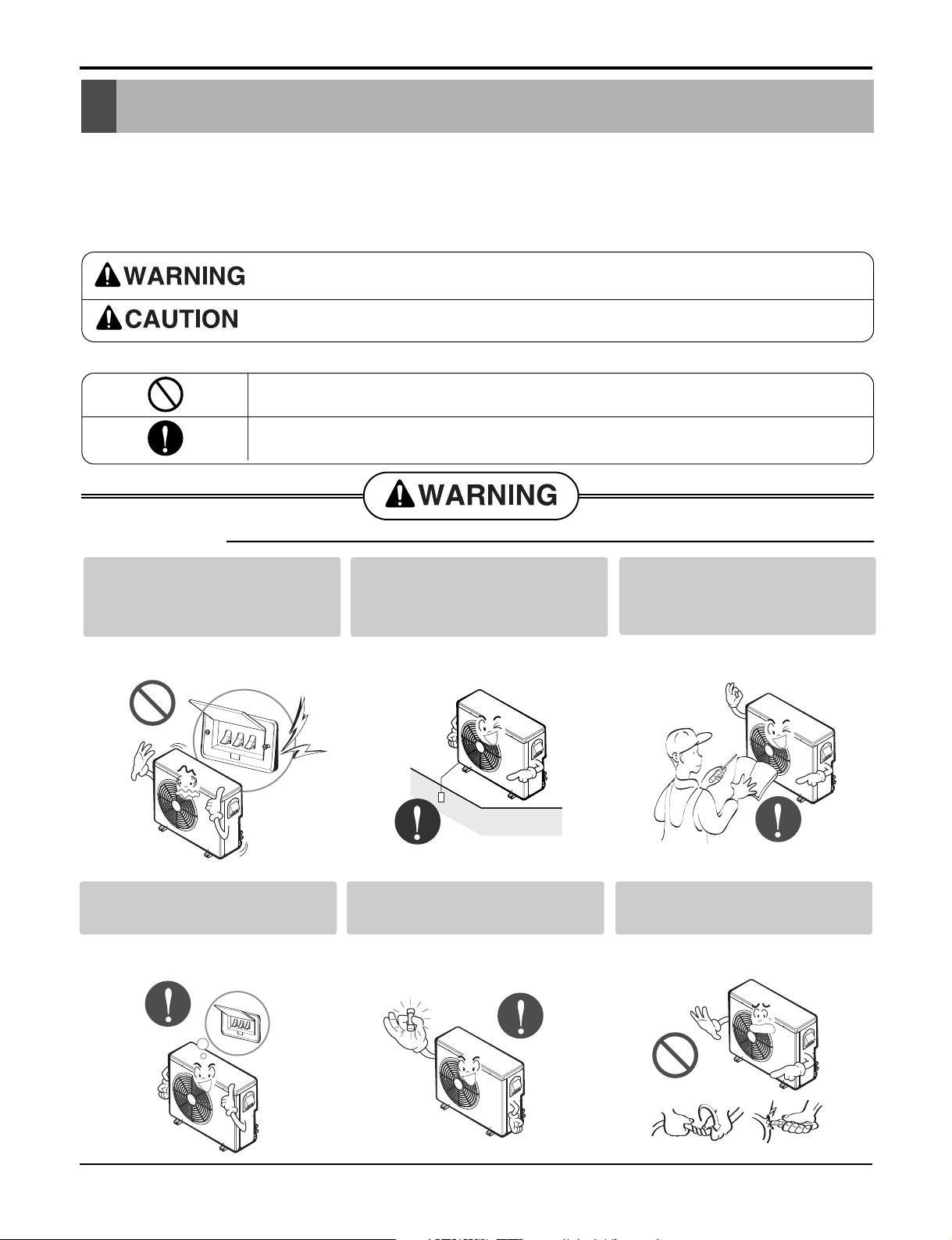
■ Installation
Be sure not to do.
Be sure to follow the instruction.
Do not use a defective or underrated circuit breaker. Use this
appliance on a dedicated circuit.
• There is risk of fire or electric
shock.
Always ground the product.
• There is risk of fire or electric
shock.
Install the panel and the cover
of control box securely.
• There is risk of fire or electric
shock.
Always install a dedicated circuit and breaker.
• Improper wiring or installation may
cause fire or electric shock
Use the correctly rated breaker or fuse.
• There is risk of fire or electric
shock.
Do not modify or extend the
power cable.
• There is risk of fire or electric
shock.
Safety Presautions
Page 5
Service Manual 5
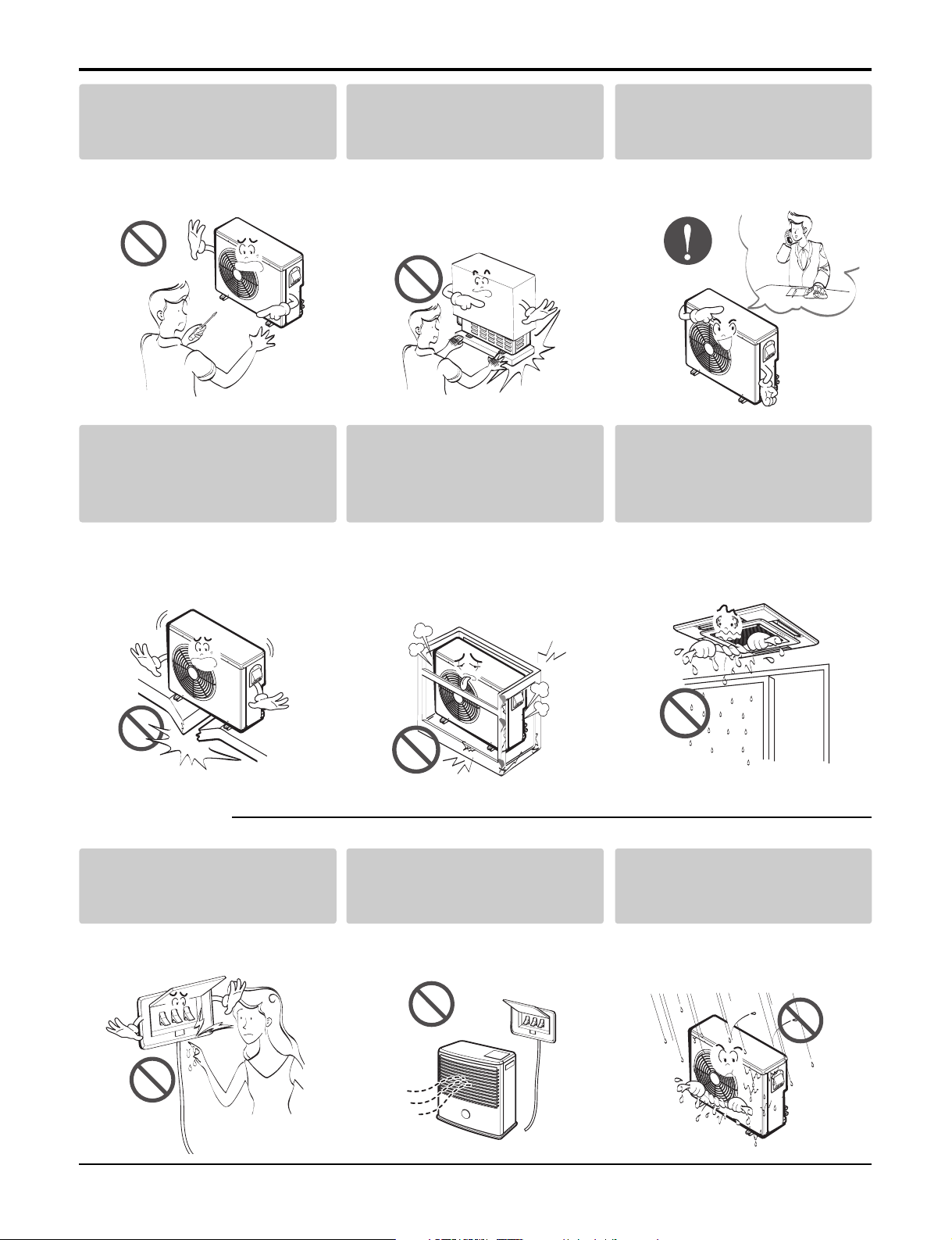
■ Operational
Do not install, remove, or reinstall the unit by yourself
(customer).
• There is risk of fire, electric shock,
explosion, or injury.
Be cautious when unpacking
and installing the product.
• Sharp edges could cause injury.
Be especially careful of the case
edges and the fins on the condenser and evaporator.
For installation, always contact the dealer or an
Authorized Service Center.
• There is risk of fire, electric shock,
explosion, or injury.
Do not install the product on a
defective installation stand.
• It may cause injury, accident, or
damage to the product.
Be sure the installation area
does not deteriorate with age.
• If the base collapses, the air conditioner could fall with it, causing
property damage, product failure,
and personal injury.
Do not let the air conditioner
run for a long time when the
humidity is very high and a
door or a window is left open.
• Moisture may condense and wet or
damage furniture.
Do not touch(operate) the
product with wet hands.
• There is risk of fire or electrical
shock.
Do not place a heater or other
appliances near the power
cable.
• There is risk of fire or electric
shock.
Do not let electric parts of the
product get wet.
• There is risk of fire, failure of the
product, or electric shock.
Safety Presautions
Page 6
6 Ceiling Cassette Air Conditioner
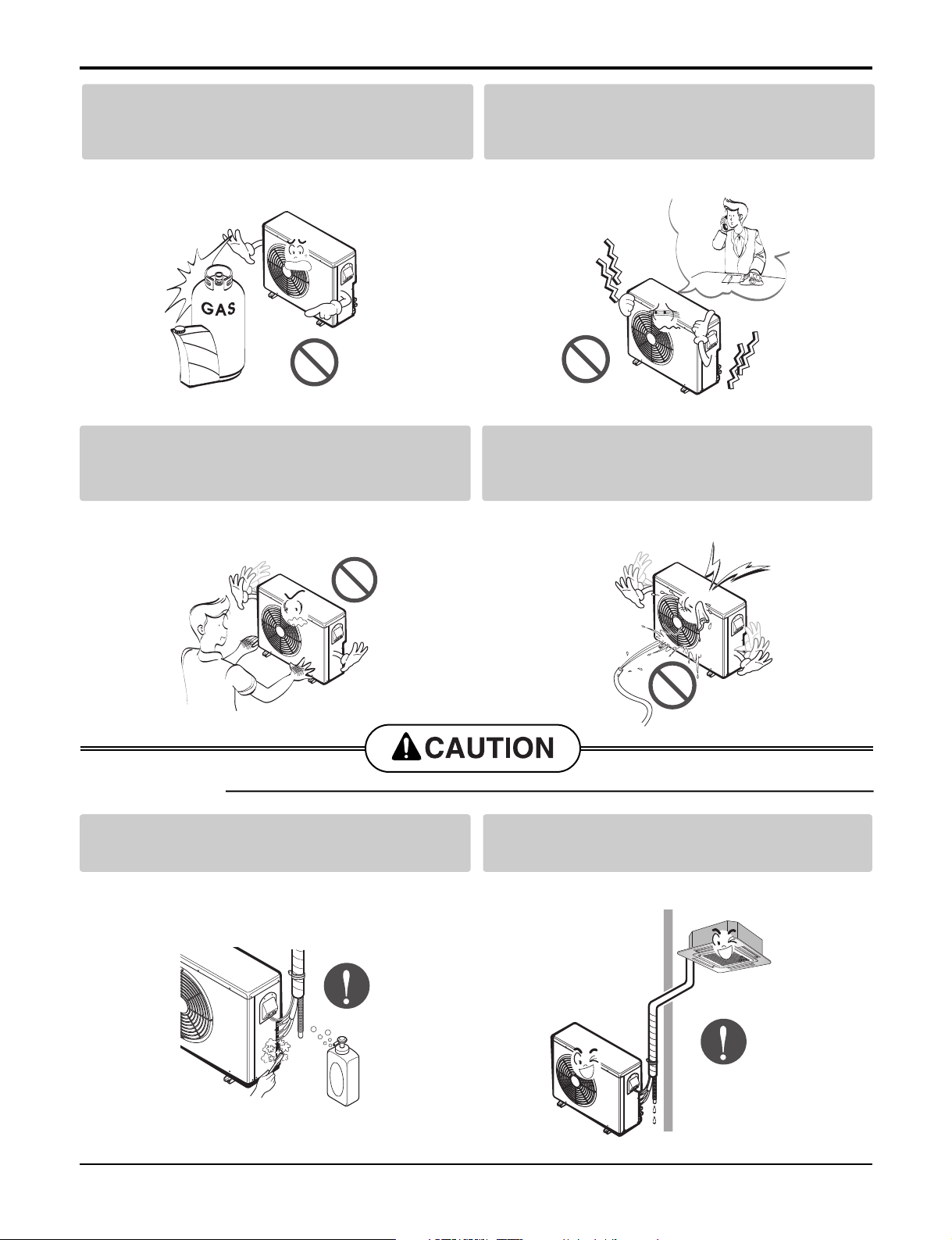
■ Installation
Do not open the inlet grill of the product during
operation. (Do not touch the electrostatic filter,
if the unit is so equipped.)
• There is risk of physical injury, electric shock, or product failure.
Be cautious that water could not enter the
product.
• There is risk of fire, electric shock, or product damage.
Always check for gas (refrigerant) leakage after
installation or repair of product.
• Low refrigerant levels may cause failure of product.
Install the drain hose to ensure that water is
drained away properly.
• A bad connection may cause water leakage.
Do not store or use flammable gas or combustibles near the product.
• There is risk of fire or failure of product.
If strange sounds, or small or smoke comes
from product. Turn the breaker off or disconnect the power supply cable.
• There is risk of electric shock or fire.
Safety Presautions
Gasolin
Page 7
Service Manual 7
Keep level even when installing the product.
• To avoid vibration or water leakage.
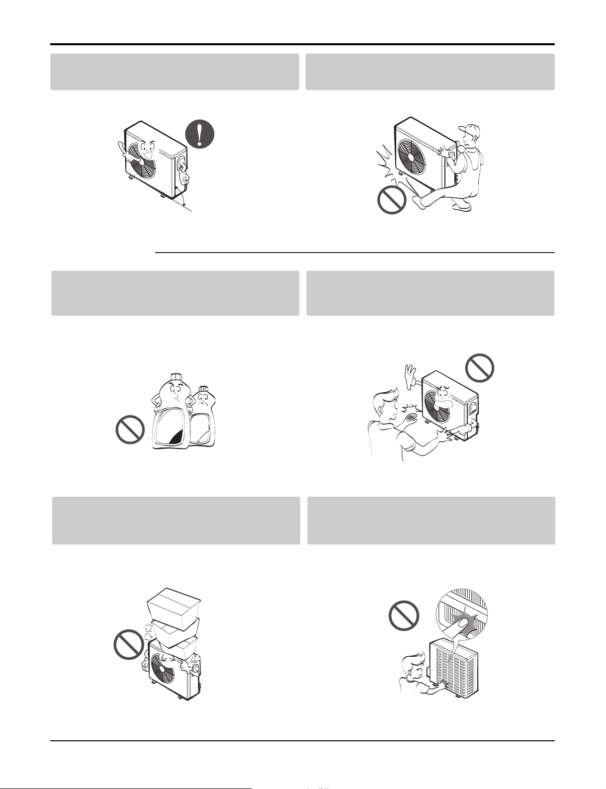
Use two or more people to lift and transport
the product.
• Avoid personal injury.
Use a soft cloth to clean. Do not use harsh
detergents, solvents, etc.
• There is risk of fire, electric shock, or damage to the
plastic parts of the product.
Do not touch the metal parts of the product
when removing the air filter. They are very
sharp!
• There is risk of personal injury.
Do not step on or put anyting on the product.
(outdoor units)
• There is risk of personal injury and failure of product.
Do not insert hands or other objects through
the air inlet or outlet while the product is operated.
• There are sharp and moving parts that could cause
personal injury.
■ Operational
Safety Presautions
90˚
Thinner
Wax
Page 8

8 Ceiling Cassette Air Conditioner
Features & Benefits
Environment Friendly Refrigerant :
- LG Ceiling Cassette Air Conditioners uses environment friendly refrigerant, which don't do any harm to
the environment.
Plasma Air Purifier :
- It removes not only microscopic contaminants &
dust, but also house mites, pollen, and pet fur to help
preventing allergic diseases like asthma.It provides
odor free, dust free and allergy free air.
Group Control :
- It enables to control as much as 16 units with the
help of one wired remote controller. All the units will
follow same setting of temperature & other sub functions.
Central Control :
- It enables to control 16 x 8 = 128 units with the help
of 8 controllers. All units can be put on and off from
one Central Room. For Setting Temperature, Fan
Speed and other sub functions, access the respective LCD wired remote controller of each unit.
Jet Cool :
-In this mode, quick and fast cooling is done. Cold and
high velocity air is supplied to the room till the indoor
temperature reaches 18°C(64°F). The unit will continue to run in jet cool mode till the Indoor temperature
reaches 18°C(64°F).
12 16........
........
IonizerPre-filter
Dust particles
dusts
Odour
Dust
electrode
discharge
Odor molecule
+6.5KV
discharge
aluminum coated
electrode(-)
(3.25KV discharge)
Generating
plasma
+
+
+
+
+
Dusts Collection
Polluted
Air
Purified
fresh Air
Main
PCB
Controller
# 1
Controller
# 2
Controller
# 8
M
1
Sub
1
M
2
Sub
2
M
16
Sub
16
M
17
Sub
17
M
18
Sub
18
M
128
Sub
128
Features & Benefits
Page 9
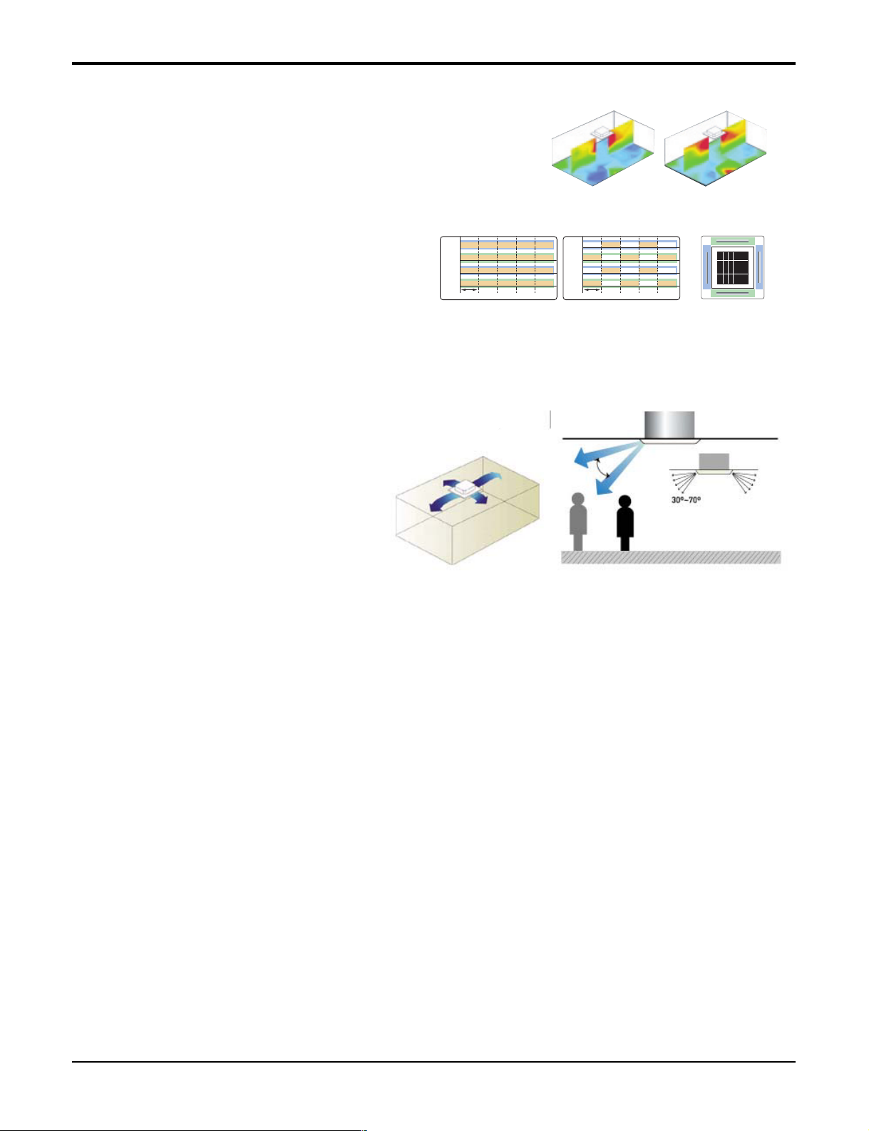
Swirl Swing
- It is the function for comfort cooling/heating operation.
- The diagonal two louvers are opened the
more larger than the other louvers.
After one minute, it is opposite.
Space Control
Vanes angle can be controlled by pair, considering its
installation environment.
- For example direct drafts can be annoying, leading
to discomfort and reduced productivity vane control
helps to eliminate this problem.
- Easily controlled by wired remote control.
- Air Flow can be controlled easily regarding any
space environment.
Auto Restart Operation :
- Whenever there is electricity failure to the unit, and after resumption of the power, unit will start in the same
mode prior to the power failure. Memorized condition are on / off condition, operating mode, set temperature
and fan speed.The unit will memorize the above conditions and start with same memorized condition.
Two Thermistor Control :
- There may be a significant difference between the temperature taken at the installed product and indoor temperature. Two thermistor control provides option to control temperature by referring any of the two temperatures. With the help of the slide switch at the back of the LCD wired remote controller, selection of the desired
thermistor for controlling the unit can be done. One thermistor is in the Indoor unit & the other one is in the
LCD wired remote.
Service Manual 9
Features & Benefits
71
Vane 2
Swirl Swing(New)4- Open(Conventional)
Swirl Swing(New)4- Open(Conventional)
2.4% 4.8%100% Improved
Comparison of Air Flow Types
Comparison of Floor
Temp. Distribution(20°C)
Vane 1 Close OpenOpen
Open
Open
Open
Close CloseOpen
Vane 3 Close Open Close CloseOpen
OpenOpen Close CloseOpen
Vane 2
OpenOpen
Time
Close CloseOpen
Vane 4
Vane 1
Vane 3
Vane 2
Time
Vane 4
Vane 3
Vane 4
Vane 1
Page 10
10 Ceiling Cassette Air Conditioner
Features & Benefits
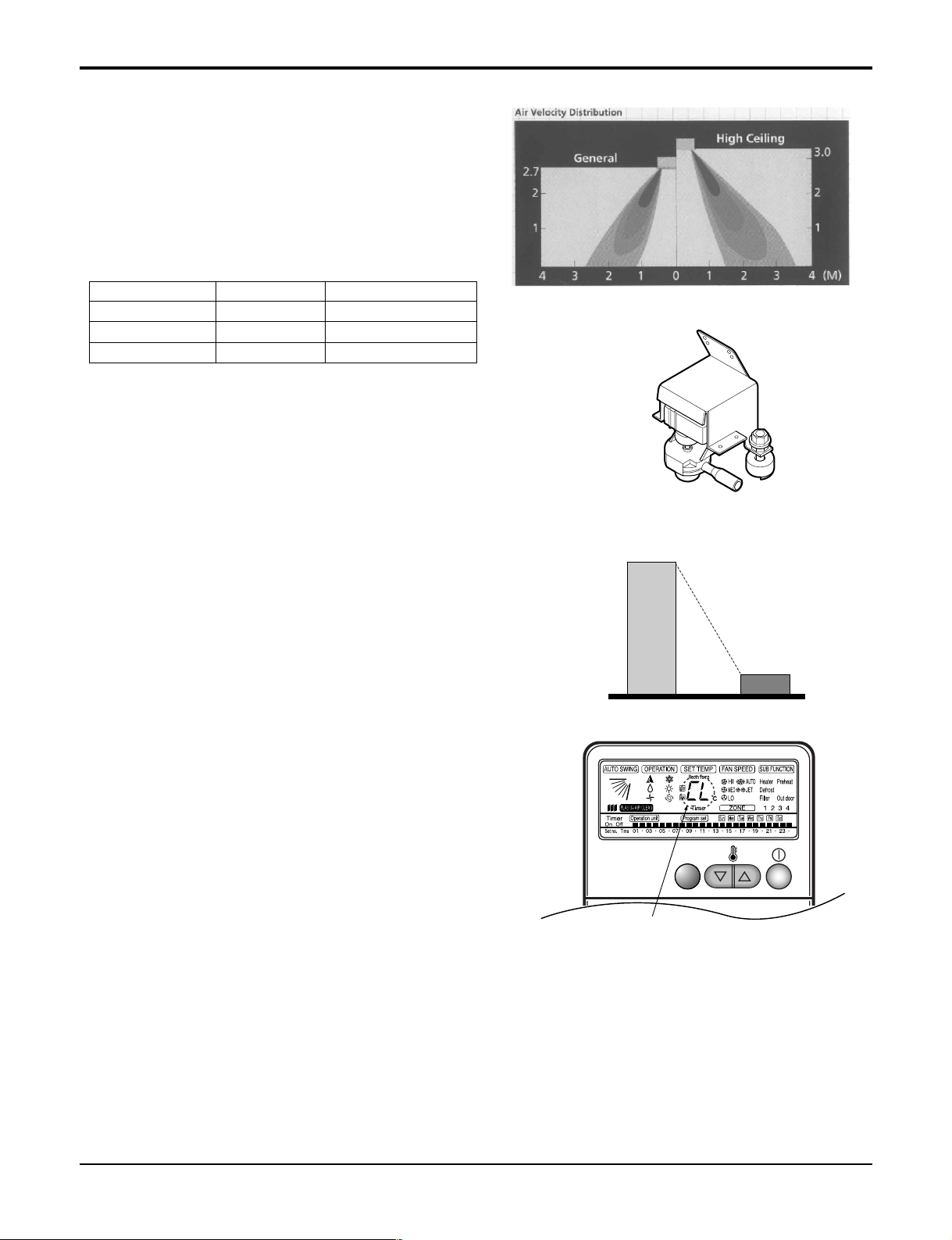
High Ceiling Operation
- According to the height of ceiling installation, it provides variability of indoor fan motor rpm. If the height
of installation is low then you can adjust low rpm of
indoor fan motor. On the other hand if the height of
the installation is high you can adjust high rpm of
indoor fan motor. Selection of speed can be done by
slide switch at the back of the LCD wired remote.
ex:
Water Drain Pump :
- In some of the places natural drainage is not possible. For such places drain pump is very useful. It
removes condensed water from the unit.
Time Delay Safety Function :
- It delays restarting of the compressor by three minutes thereby preventing damage to the compressor.
Zero Standby Power:
- Due to SMPS (Switching Modulation Power Supply)
technology, there is almost zero power consumption
in the standby mode.
Child Lock Function:
-It prevents the children or others from tampering the
control buttons. Unit can be controlled by the wireless
remote controller. This can be easily set by pressing
timer key & Min key simultaneously. After child lock is
set, pressing any key will displaye CL on the LCD for
3 seconds and all the keys will be ineffective.
Self Diagnosis Function:
- This function provides diagnosis of the unit. An
error code will be displayed on the LCD wired
remote controller & diagnosis can be done as per
the code indication. The same is also printed on
key cover of the LCD wired remote controller.
5~6W
Others LG
0.5W
CHILD LOCK
-Display
Selection Height RPM
Lower 2.4m(7.9ft) 700/600/500
Standard 2.7m(8.9ft) 750/650/550
Higher 3.0m(9.8ft) 800/700/600
Page 11
Service Manual 11
List of Functions
• Ceiling Cassette
List of Functions
Air supply outlet
Airflow direction control (left & right)
Airflow direction control (up & down)
Auto swing (left & right)
Air flow
Auto swing (up & down)
Airflow steps(Fan / Cool / Heat)
CHAOS swing
CHAOS wind (Auto wind)
Jet cool (Power wind)
Swirl wind
Deodorizing filter
Air purifying Plasma air purifier
Prefilter(Washable)
Drain pump
Installation
E.S.P. control
Electric heater (Operation)
High ceiling operation
Hot start
Reliability Self diagnosis
Soft dry operation
Auto changeover
Auto cleaning
Auto operation(Artificial intelligence)
Auto restart operation
Convenience
Child lock
Forced operation
Group control
Sleep mode
Timer (On/Off)
Timer (weekly)
Two thermistor control
Standard wired remote controller
Deluxe wired remote controller
Individual Control
Simple wired remote controller
Wired remote controller(for hotel use)
Wireless remote controller(simple)
Wireless LCD remote controller
General central control(Non LGAP)
CAC Network
Dry contact
Function
Simple central control(LGAP)
PDI(Power Distribution Indicator)
PI 485
Special Function Kit
CTIE
Zone control
Others Thermistor
44
XX
Auto Auto
XX
OO
3/4/- 3/4/-
XX
XX
OO
OO
XX
OO
OO
OO
--
-OO
XX
OO
OO
XX
XX
OO
OO
OO
OO
Option Option
-OO
OO
OO
OO
--
--
--
--
PQWRHSF0 PQWRHSF0
Option Option
Option Option
Option Option
Option Option
Option Option
XX
XX
--
FunctionCategory
AT-C243HLF0 AT-C343HLF0
Note :
O : Applied, X : Not applied, – : No relation
Option: Model name & price are different according to options, and assembled in factory with main unit.
Accessory: Installed at field, ordered and purchased separately by the corresponding model name, supplied with separate package.
Page 12
12 Ceiling Cassette Air Conditioner
Function of Remote Control
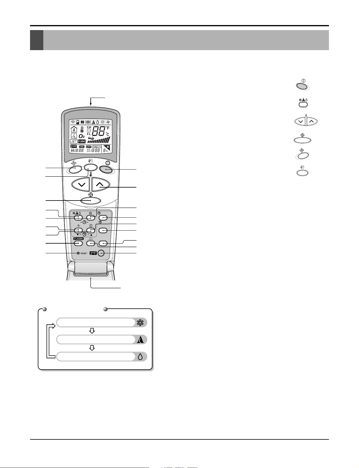
1. Wireless LCD Remote Control
Function of Remote Control
Cooling Operation
Auto Operation
Healthy Dehumidification Operation
Operation Mode
ON
OFF
CANCEL
SET
°C/°F
AUTO CLEAN
1
3
5
4
9
10
12
18
16
7
2
8
13
15
11
6
Flip-up door
(opened)
Signal transmitter
17
14
1. START/STOP BUTTON
Operation starts when this button is pressed and
stops when the button is pressed again.
2. OPERATION MODE SELECTION BUTTON
Used to select the operation mode.
3. ROOM TEMPERATURE SETTING BUTTONS
Used to select the room temperature.
4. INDOOR FAN SPEED SELECTOR
Used to select fan speed in four steps
low, medium and high.
5.
JET COOL
Used to start or stop the speed cooling.(speed cooling
operates super high fan speed in cooling mode.)
6. AUTO SWING BUTTON
Used to stop or start louver movement and set the
desired up/down airflow direction.
7. ON/OFF TIMER BUTTONS
Used to set the time of starting and stopping operation.
8. TIME SETTING BUTTONS
Used to adjust the time.
9. TIMER SET/CANCEL BUTTON
Used to set the timer when the desired time is
obtained and to cancel the Timer operation.
10. SLEEP MODE AUTO BUTTON
Used to set Sleep Mode Auto operation.
11. AIR CIRCULATION BUTTON
Used to circulate the room air without cooling.
12. ROOM TEMPERATURE CHECKING BUTTON
Used to check the room temperature.
13. PLASMA AIR CLEAN BUTTON
Used to start or stop the plasma-purification function.
14. HORIZONTAL AIRFLOW DIRECTION CONTROL
BUTTON (OPTIONAL)
Used to set the desired horizontal airflow direction.
15. RESET BUTTON
Used prior to resetting time.
16. 2nd F Button
Used prior to using modes printed in blue at the bottom of buttons.
17. AUTO CLEAN (OPTIONAL)
Used to set Auto Clean mode.
18. °C/°F SWITCH BUTTON
Used to switch temperature reading from Centigrade
to Fahrenheit.
❈ The wireless remote controller do not operate the swirl mode.❈ The wireless remote controller do not operate the swirl mode.
Page 13

Service Manual 13
Function of Remote Control
Timer Cancel 2ndF
Program Week
Hour Min
Holiday
Set/Clr
RESET
Plasma
Operation unit
Humidify
AUTO SWING OPERATION
FAN SPEED
Program set
SUB FUNCTION
SET TEMP
Room Temp
HI
MED
LO
Heater
Defrost
Filter
Preheat
Out door
Time
Timer
On
Set no. Time
Off
01 03 05 07 09 11 13 15 17 19 21 23
3
10
12
14
15
11
13
18
16
2
6
1
5
4
8
9
7
17
1234
ZONE
2ndF
No Func
AUTO
JET
SLo
1 Operation display
Displays the operation conditions.
2 On/Off Button
Operation starts when this button is pressed, and
stops when the button is pressed again.
3 Set Temperature Button
Used to set the temperature when the desired temperature is obtained.
4 FAN Operation Button
Used to circulate room air without cooling.
5 Fan Speed & Jet Cool Button
Used to set the desired fan speed and select jet
cool mode.
6 Operation Mode Selection Button
Used to select the operation mode.
• Auto Operation Mode
• Cooling Operation Mode
• Soft Dry Operation Mode
7 Auto Swing Button
Used to swing up and down.
8 Room Temperature Checking Button
Used to check the room temperature.
9 Plasma Air Clean Button
Used to start or stop the plasma-purification function.
10 Timer Cancel Button
Used to cancel the timer.
11 Timer Set Button
Used to set the timer when the desired time is
obtained.
12 Week Button
Used to set a day of the week.
13 Program Button
Used to set the weekly timer.
14 Holiday Button
Used to set a holiday of the week.
15 Time Set Button
Used to set the time of the day and change the
time in the weekly timer Function.
16 Set and Clear Button
Used to set and clear the weekly timer.
17 Swirl Button
Used to select swirl swing mode.
18 Reset Button
Used to set the current time and clear the setting
time.
2. Wired LCD Remote Control
Page 14
14 Ceiling Cassette Air Conditioner
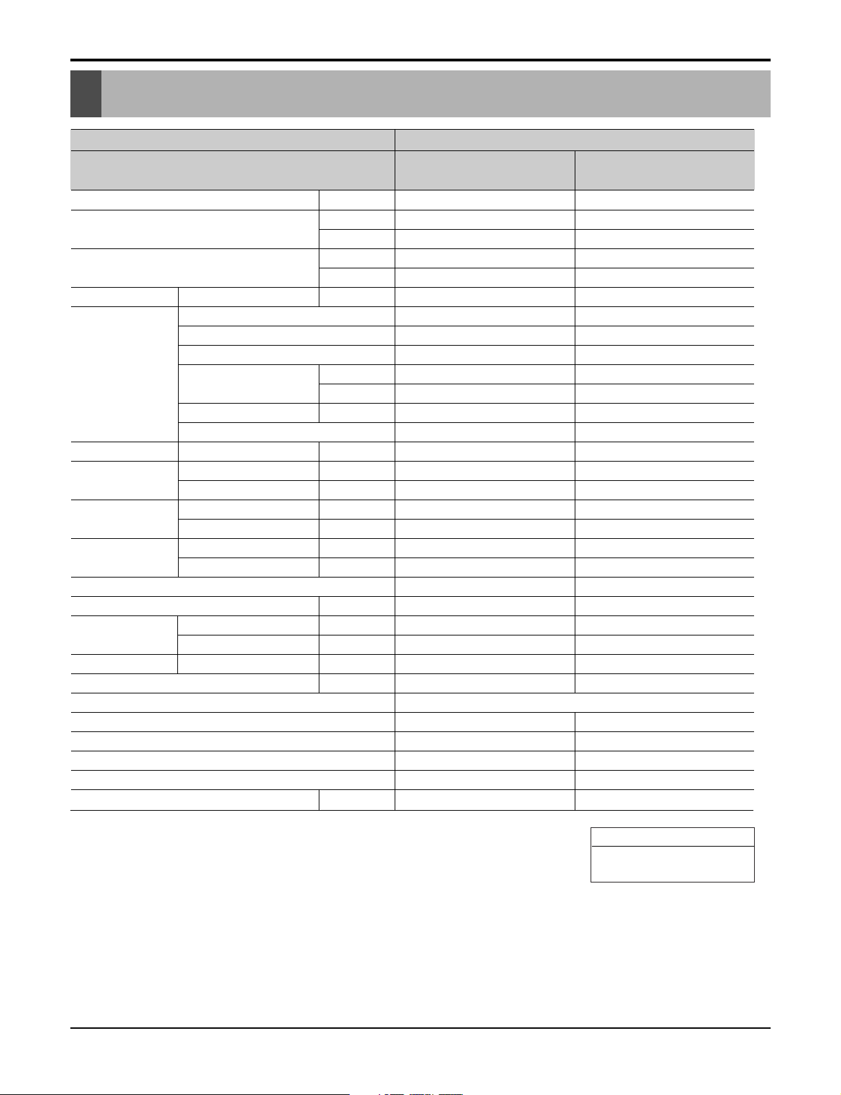
Specifications
Specifications
Note :
1. Capacities are based on the following conditions:
Cooling: - Indoor Temperature 26.7°C(80°F) DB /19.4°C(67°F) WB
- Outdoor Temperature 35°C(95°F) DB /23.9°C(75°F) WB
Piping Length - Interconnecting Piping Length 7.5m(25ft)
- Level Difference of Zero.
Conversion Formula
kW = Btu/h × 0.0002931
CFM = CMM × 35.3
Power supply
Phase/Volts/Hz
Cooling capacity kW
Btu/h
Heating capacity kW
Btu/h
Current Nominal running current A
Fan Motor Type
Fan Type
Motor Output(W) * number of units
Air flow rate (H/M/L) cmm
cfm
Capacitor mF/V
Drive
Coil Row * stages * FPI mm
Dimensions Body mm(inch)
(W*D*H) Decorative Panel mm(inch)
Net Weight Body kg(lbs)
Decorative Panel kg(lbs)
Gross Weight Body kg(lbs)
Decorative Panel kg(lbs)
Air filter
Sound Level (H/M/L) dB(A)+3
Piping Connections Liquid mm(inch)
Gas mm(inch)
Drain OD/ID mm(inch)
Dehumidification rate l/h(pts/h)
Safety Devices
Temperature sensor
Refrigerant
Refrigerant control
Connectable outdoor Unit
Power and Transmission interunit cable
No.* mm2 (No. AWG)
Model
AT-C243HLF0
(LCN240CP / LC240CPI)
AT-C343HLF0
(LCN340CP / LC340CPI)
Indoor unit type Ceilling Cassette - 4way
1 / 208-230 / 60 1 / 208-230 / 60
7.03 9.96
24,000 34,000
--
--
1.0 1.0
BLDC BLDC
Turbo Fan Turbo Fan
50.6 * 1 50.6 * 1
18.4/17.0/15.6 24.1/22.7/21.2
650/600/550 850/800/750
--
DC DC
2R * 9C * 18 2R * 9C * 18
840 * 840 * 225(331/
16 * 33
1
/
16 * 8
7
/
8) 840 * 840 * 225(33
1
/
16 * 33
1
/
16 * 8
7
/
8)
950 * 950 * 30(37
13
/32 * 3713/32 * 13/16) 950 * 950 * 30(3713/32 * 3713/32 * 13/16)
26(57.3) 26(57.3)
3(6.61) 3(6.61)
30(66) 30(66)
4(9) 4(9)
Long Life filter Long Life filter
38/35/32 40/37/34
6.35(1/4) 6.35(1/4)
12.7(1/2) 15.88(5/8)
32/25(1.26/0.98) 32/25(1.26/0.98)
3.0(6.3) 3.7(7.8)
Fuse, Thermal protector for Fan motor
Thermistor Thermistor
R410A R410A
EEV EEV
Single Single
4 * 2.1(14) 4 * 2.1(14)
Page 15

Service Manual 15
Specifications
Rated Capacity Cooling kW
Btu/h
Heating kW
Btu/h
Rated Input Cooling kW
Heating kW
Energy Label
Testing combination
Running current Cooling A
Heating A
Starting current (Cooling/Heating) A
Power supply Phase / Volts / Hz
Power supply Cable(outdoor)
No. * mm2(No. AWG)
Power and transmission cable
No. * mm2(No. AWG)
Dimensions W * H * D mm(inch)
Net weight kg(lbs)
Gross weight kg(lbs)
Maximum number of connectable unit
Compressor Type
(constant) Qty * model
Motor Type
Oil charge volume cc
Oil type
Refrigerant
Charge(at 7.5m(25ft))
g(oz)
Type
Control
Heat Exchanger Rows * Column * FPI
Defrosting method
Fan Capacitor mF/Vac
Drive
Discharge Direction
Side / Top
Air flow rate cmm(cfm)
Noise level(H) Sound press, 1m db (A) + 3
Piping connections Liquid mm(inch)
Gas mm(inch)
Max. piping length Main piping m(ft)
Max. elevation
Indoor unit - Outdoor unit
m(ft)
7.03 9.96
24,000 34,000
--
--
2.5 3.6
--
--
--
11.5 17
--
24 38
1 / 208-230 / 60 2 / 208-230 / 60
3 * 2.1(14) 3 * 3.3(12)
4 * 2.1(14) 4 * 2.1(14)
870 * 800 * 320(341/
2 * 31
1
/
2 * 12
19
/
32) 900 * 1160 * 370(35
7
/
16 * 45
11
/
16 * 14
9
/
16)
73(160) 86(190)
78(172) 93(205)
11
ROTARY ROTARY
2*GK120KAA GJ151KAA + GJ208KAA
Induction Induction
700 1200
PVE PVE
2100(74.1) 2500(88.2)
R410A R410A
EEV EEV
2R * 36C * 20 2R * 52C * 18
- -
6 / 370 6 / 370
Direct Drive Direct Drive
Side discharge Side discharge
51(1801) 105(3708)
55 58
6.35(1/4) 6.35(1/4)
12.7(1/2) 15.88(5/8)
30(100) 35(115)
15(50) 20(66)
AT-C243HLFO
(LCU240CP / LC240CPO)
AT-C343HLFO
(LCU340CP /LC340CPO)
Outdoor Unit
Note :
1. Capacities are based on the following conditions:
Cooling: - Indoor Temperature 26.7°C(80°F) DB /19.4°C(66.9°F) WB
- Outdoor Temperature 35°C(95°F) DB /23.9°C(75°F) WB
Piping Length - Interconnecting Piping Length 7.5m(25ft)
- Level Difference of Zero.
Conversion Formula
kW = Btu/h × 0.0002931
CFM = CMM × 35.3
Page 16

16 Ceiling Cassette Air Conditioner
225(8.9)
950(37.4)
950(37.4)
840(33.1)
7
76(3.0)
135(5.3)
4
5
225(8.9)
6
806(31.7)
840(33.1)
840(33.1)
688(27.1)
950(37.4)
30(1.18)
950(37.4)
R35(1.4)
3
2
1
900(35.4) (ceiling opening)
688(27.1) (hanging bolt)
840(33.1)
900(35.4) (ceiling opening)
950(37.4)
806(31.7) (hanging bolt)
840(33.1)
Drain pipe connection
Air suction grille
Part Name
Decoration panel
Air discharge grille
Liquid pipe connection
Gas pipe connection
6
5
No.
2
4
3
1
Remark
7
Power supply connection
* mm(inch)
Dimensional Drawings
1. Indoor Units
Model No.: LCN240CP/LC240CPI/LCN340CP/LC340CPI
Dimensional Drawings
Page 17

Service Manual 17
870(34.3)
546(21.5)
54.6(2.1)
333(13.1)
Ø531(20.9)
10(0.4)
808(31.8)
782.5(30.8)
392(15.4)
25.5(1.0)
80(3.1)
50(2.0)
320(12.6)
320(12.6)
340(13.4)
360(14.2)
160(6.3)
*mm(inch)
Dimensional Drawings
Model No.: LCU240CP/LC240CPO
2. Outdoor Units
Page 18

18 Ceiling Cassette Air Conditioner
Dimensional Drawings
Model No.: LCU340CP/LC340CPO
Gas pipe connection
Part Name
Air discharge grille
Liquid pipe connection
Earth screw
Power & transmission connection
5
No.
2
4
3
1
Remark
5
1135(44.7)
1165(45.9)
308(12.1)
565(22.2)
273(10.7)
520(20.5)
80(3.1)
124(4.9)
900(35.4)
550(21.7)
370(14.6)
395(15.6)
15(0.6)
175(6.9)
3
2
65(2.6)
4
370(14.6)
1
*mm(inch)
Page 19
Service Manual 19
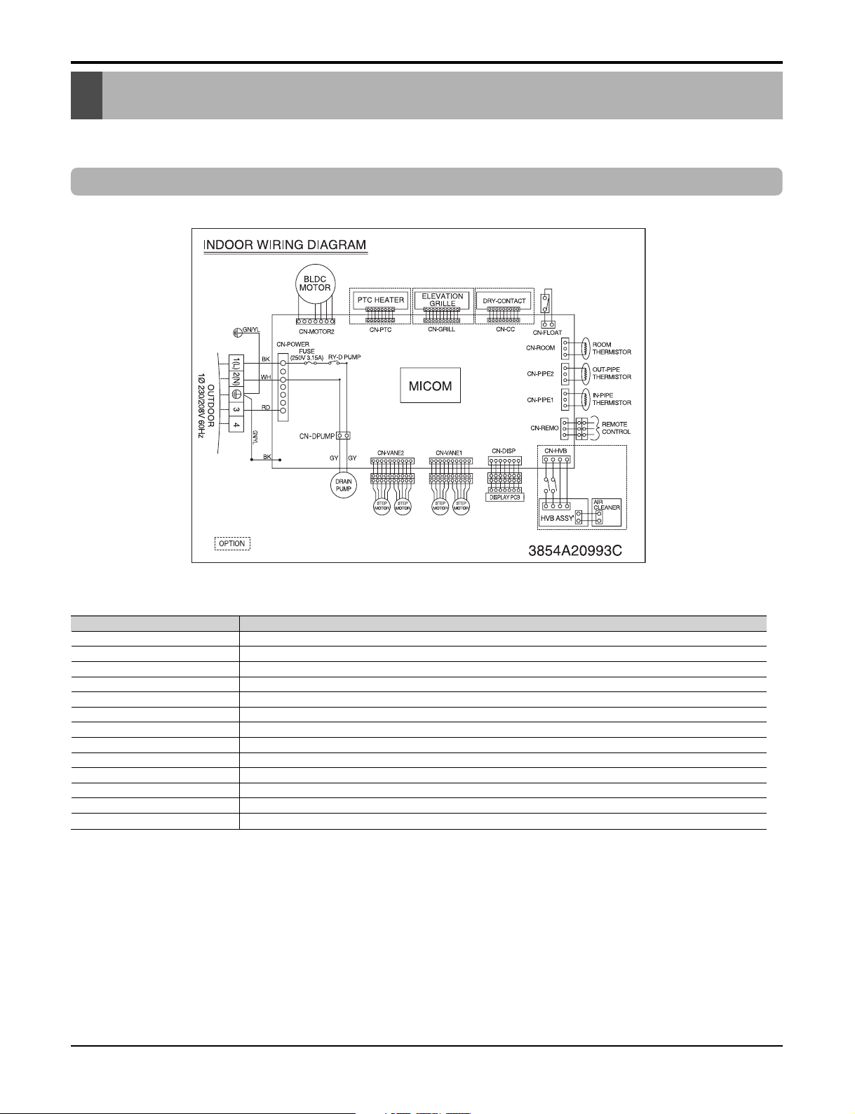
Wiring Diagrams
1. Indoor Unit
LCN240CP/LC240CPI/LCN340CP/LC340CPI
Wiring Diagrams
Connector Number Location
CN-POWER AC power supply
CN-MOTOR BLDC fan motor output
CN-DPUMP Drain pump output
CN-DISP Display
CN-FLOAT Float switch input
CN-REMO Remote control
CN-CC Dry-contact
CN-ROOM Room sensor
CN-PIPE1 In-pipe thermistor
CN-PIPE2 Out-pipe thermistor
CN-GRILL Elevation grille
CN-PTC PTC Heater
CN-HVB HVB Ass'y (Air cleaner)
Page 20

20 Ceiling Cassette Air Conditioner
Wiring Diagrams
LCU240CP/LC240CPO
LCU340CP/LC340CPO
2. Outdoor Unit
Notes:
BL
BLUE
RD
RED
YL
YELLOW
BK
OR
GN/YL
BLACK
ORANGE
GREEN/YELLOW
BR
WH
BROWN
WHITE
FIELD WIRING
Notes:
BL
BLUE
RD
RED
YL
YELLOW
GN/YL
BK
BLACK
OR
ORANGE
GREEN/YELLOW
BR
WH
BROWN
WHITE
FIELD WIRING
Page 21

Service Manual 21
Refrigerant Cycle Diagrams
1. Cooling Only Models
INDOOR UNIT
H/EX
LIQUID SIDE
Gas Side
GAS SIDE
Capillary Tube
OUTDOOR UNIT
Thermistor
(Air)
E.E.V.
Accumulator
Heat
Exchanger
Check
Valve
Constant
Compressor 1
Constant
Compressor 2
Check
Valve
Thermistor
Thermistor
High
pressure
S/W
Thermistor
24k
34k
Gas Liquid Rated Max. Rated Max.
Pipe Size(Diameter:Ø) inch
Piping length (ft.) Elevation (ft.)
Capacity
Additional
Refrigerant
(oz/ft)
1/4
1/4
1/2
5/8
25
100
115
50
66
16
16
Refrigerant Cycle Diagrams
0.22
0.32
Page 22

22 Ceiling Cassette Air Conditioner
Installation
More than
30cm(11.8inch)
Fence or
obstacles
Sunroof
More than 50cm(19.7inch)
(Service space)
More than
30cm(11.8inch)
More than 50cm(19.7inch)
More than 70cm(27.6inch)
More than 50cm(19.7inch)
More than
100cm(39.4inch)
More than
50cm(19.7inch)
More than
50cm(19.7inch)
1.2 Outdoor Unit
• If an awning is built over the unit to prevent direct sunlight or rain exposure, make sure that heat radiation from
the condenser is not restricted.
• Ensure that the space around the back is more than 30cm(11.8inch) and sides is more than 30cm(11.8inch).
The front of the unit should have more than 70cm(27.6inch) of space.
• Do not place animals and plants in the path of the warm air.
• Take the air conditioner weight into account and select a place where noise and vibration are minimum.
• Select a place so that the warm air and noise from the air conditioner do not disturb neighbors.
• Rooftop Installations : If the outdoor unit is installed on a roof structure, be sure to level the unit. Ensure the
roof structure and anchoring method are adequate for the unit location. Consult local codes regarding rooftop
mounting.
1. Select the best location
Install the air conditioner in the location that satisfies the following conditions.
1.1 Indoor Unit
• There should not be any heat source or steam near the
unit.
• There should not be any obstacle to the air circulation.
• A place where air circulation in the room will be good.
• A place where drainage can be easily obtained.
• A place where noise prevention is taken into considera-
tion.
• Do not install the unit near the door way.
• Ensure the spaces indicated by arrows from the wall,
ceiling, or other obstacles.
• The indoor unit must have sufficeient maintenance
space.
Unit:cm(inch)
Ceiling
Ceiling Board
Ceiling Board
30(11.8)
or more
Above 250(98.4)
400(157.5) or less
100(39.4)
or more
50(19.7)
or more
50(19.7)
or more
30(11.8) or less
Floor
Installation
Sunroof
Fence or
obstacles
Page 23

Service Manual 23
Installation
Bolt
Tubing connection
2. Settlement of outdoor unit
• Anchor the outdoor unit with a bolt and
nut(ø10mm(0.39inch)) tightly and horizontally on a
concrete or rigid mount.
• When installing on the wall, roof or rooftop, anchor
the mounting base securely with a nail or wire assuming the influence of wind and earthquake.
• In the case when the vibration of the unit is conveyed
to the hose, secure the unit with an anti-vibration rubber.
Wall
5~7mm
(0.20~0.28inch)
Indoor Outdoor
3. Indoor Unit Installation
• The following parts is option.
Hanging Bolt - W 3/8 or M10
Nut - W 3/8 or M10
Spring Washer - M10
Plate Washer - M10
• Drill the piping hole on the wall slightly tilted to
the outdoor side using a Ø 70(2.76inch) hole-core
drill.
Set screw of
paper model (4 pieces)
Paper model
for installation
Ceiling board
150mm(5.91inch)
Adjust the same height
Ceiling board
Ceiling
Flat washer for M10
(accessory)
Keep the length of the bolt
from the bracket to 40mm(1.57inch)
Open the ceiling board
along the outer edge of the
paper model
Flat washer for M10
(accessory)
Hanging bolt
(W3/8 or M10)
Nut
(W3/8 or M10)
Nut
(W3/8 or M10)
Spring washer
(M10)
Air Conditioner body
• Tighten the nut and bolt to prevent unit falling.
CAUTION
Page 24

24 Ceiling Cassette Air Conditioner
Installation
4. Wiring Connection
Make sure that the screws of the terminal are free from looseness.
1. All wiring must comply with LOCAL REGULATIONS.
2. Select a power source that is capable of supplying the current as required by the air conditioner.
3. Feed the power source to the unit via a distribution switch board designed for this purpose.
4. The terminal screws inside the control box may be loose due to vibration during transport.
Check the screws for loose connection.
(Running the air conditioner with loose connection can overload and damage electrical components.)
5. Always ground the air conditioner with a grounding wire and connector to meet the LOCAL REGULATION.
24k/34k Btu/h (1Ø)
• Cooling & Heating type
Terminals on the indoor unit
1(L)
2(N) 3 4 5
Terminals on the outdoor unit
POWER
INPUT
1(L) 2(N) 2(N) 31(L)
4 5
CAUTION
The power cord connected to the outdoor unit should be
complied with the following specifications (Rubber
insulation, type H05RN-F approved by HAR or SAA).
NORMAL CROSS-SECTIONAL AREA
GN/YL
Capacity
24k Btu/h
34k Btu/h
20mm(0.8inch)
2.1mm
3.3mm
1 Phase
2
(AWG 14)
2
(AWG 12)
If the supply cord is damaged, it must be replaced by a special cord or assembly available from the manufacturer of its service agent.
WARNING
The connecting cable connected to the indoor and outdoor
unit should be complied with the following specifications
(Rubber insulation, type H05RN-F approved by HAR or SAA).
NORMAL
GN/YL
CROSS-SECTIONAL
AREA 2.1mm
20mm(0.8inch)
2
(AWG 14)(24k/34k)
Page 25

Service Manual 25
Installation
5. Installation of Decoration Panel
1. Temporarily fix two decoration panel fixing screws (hexagon M5 screw) on the unit body. (Tighten by
amount 10mm(0.39inch) in length.)
The fixing screws (hexagon M5 screw) are included the indoor unit box.
2. Remove the air inlet grille from the decoration panel. (Remove the hook for the air inlet grille cord.)
3. Hook the decoration panel key hole ( ) on the screws fixed in step above, and slide the panel so
that the screws reach the key hole edge.
4. Retighten completely two temporarily fixed screws and other two screws. (Total 4 screws)
5. Connect the louver motor connector and display connector.
6. After tightening these screws, install the air inlet grille (including the air filter).
Decoration panel fixing screws
(hexagon M5 screws)
Temporally fitting at 2 places
(Tightening about 10mm(0.39inch))
Control box cover
Piping side
Inlet GrilleInlet Grille
Inlet Grille
Louver motor
Decoration panel fixing screws
(Hexagon M5 screw)
Air conditioner unit
Decoration panel
Key holes
Display
Lead wire for
louver motor and
display
The decoration panel has its installation
direction.
Before installing the decoration panel,
always remove the paper template.
Install certainly the decoration
panel.
Cool air leakage causes sweating.
Water drops fall.
Air conditioner
unit
Ceiling
board
Decoration panel
Decoration
panel
Fit the insulator (this part) and
be careful for cool air leakage
Good example
Air
Cool air leakage
(no good)
Bad example
Ceiling
board
Air conditioner unit
CAUTION
Page 26

26 Ceiling Cassette Air Conditioner
Installation
6. Heat Insulation and pipings
1. Use the heat insulation material for the refrigerant piping which has an excellent heat-resistance (over
120°C(248°F) ).
2. Precautions in high humidity circumstance:
This air conditioner has been tested according to
the "KS Standard Conditions with Mist" and con
here is not any default. However, if it is operated for
a long time in high humid atmosphere (dew point
temperature: more than 23°C(73.4°F)), water drops
are liable to fall. In this case, add heat insulation
material according to the following procedure:
• Heat insulation material to be prepared... Adiabatic glass wool with thickness 10 to 20mm(0.39 to 0.79inch).
• Stick glass wool on all air conditioners that are located in ceiling atmosphere.
• In addition to the normal heat insulation (thickness: more than 8mm(0.31inch)) for refrigerant piping (gas
piping: thick piping) and drain piping, add further 10mm to 30mm(0.39inch to 1.18 inch) thickness material.
Indoor unit
Thermal insulator
(accessory)
Fastening band
(accessory)
Refrigerant piping
HEAT INSULATION
1. Wrap the connecting portion of indoor unit with
the Insulation material and secure it with two
Plastic Bands. (for the right pipings)
• If you want to connect an additional drain hose,
the end of the drain-outlet should be kept at a
distance from the ground. (Do not dip it into
water, and fix it on the wall to avoid swinging in
the wind.)
2. Tape the Pipings, drain hose and Connecting
Cable from bottom to top.
3. Form the pipings gathered by taping along the
exterior wall and fix it to the wall by saddle or
equivalent.
In case of the Outdoor unit being installed
below position of the Indoor unit.
FORM THE PIPINGS
Trap is required to prevent water from entering
into electrical parts.
Seal a small opening
around the pipings
with gum type sealer.
Taping
Drain hose
Pipings
Connecting
cable
Plastic Band
Power supply
cord
Page 27

Service Manual 27
Installation
7. Drain Pipe Work
■ Drain Piping of Ceiling Cassette
• Drain piping must have down-slope (1/50 to 1/100): be sure not to
provide up-and-down slope to prevent reversal flow.
• During drain piping connection, be careful not to exert extra force
on the drain port on the indoor unit.
• The outside diameter of the drain connection on the indoor unit is
32mm(1.26inch).
•
Be sure to install heat insulation on the drain piping.
Piping material: Polyvinyl chloride pipe VP-25
and pipe fittings
The air conditioner uses a drain pump to drain water.
Use the following procedure to test the drain pump
operation:
• Connect the main drain pipe to the exterior and
leave it provisionally until the test comes to an end.
• Feed water to the flexible drain hose and check the
piping for leakage.
• Be sure to check the drain pump for normal operating and noise when electrical wiring is complete.
• When the test is complete, connect the flexible
drain hose to the drain port on the indoor unit.
Heat insulation material: Polyethylene foam with
thickness more than 8 mm(0.31inch).
Drain test
Maintenance
drain port
Upward
routing
not allowed
Pipe clamp
Indoor unit
700mm
(27.6inch) or less
1 -1.5m(3.32-4.92ft)
300mm
(11.81inch) or less
Clamp metal(attached) Drain hose(attached)
Drain raising pipe
Feed water
Drain Pump
Drain pan
Flexible drain hose
(accessory)
Main
drain pipe
Glue the joint
Drain
port
Drain hose connection
Use the clip (accessory)
CAUTION
The supplied flexible drain hose should not be curved,
neither screwed. The curved or screwed hose may
cause a leakage of water.
1/50~1/100
MAX 700mm
(27.6inch)
Flexible drain hoseFlexible drain hose
■
Install the drain raising pipes at a right angle to the
indoor unit and no more than 300mm(11.81inch) from
the unit.
2. Tape the Pipings and Connecting cable from bottom to top.
3. Form the pipings gathered by taping along the
exterior wall, and make the trap prevent water
from entering into the room.
4. Fix the pipings onto the wall by saddle or equivalent.
In case of the Outdoor Unit being installed
above position of the Indoor Unit.
Seal a small opening
around the pipings
with gum type sealer.
Trap
Page 28

28 Ceiling Cassette Air Conditioner
Installation
1) PRECAUTIONS IN TEST RUN
• The initial power supply must provide at least 90% of the rated voltage.
Otherwise, the air conditioner should not be operated.
For test run, carry out the cooling operation first even during winter season.
Carry out the test run more than 5 minutes without stopping.
(Test run will be cancelled 18 minutes later automatically)
• The test run is started by pressing the room temperature checking button and down timer button for 3 seconds at the same time.
• To cancel the test run, press any button.
• After completing work, be sure to measure and record trial run properties, and store measured data, etc.
• Measuring items are room temperature, outside temperature, suction temperature, blow out temperature,
wind velocity, wind volume, voltage, current, presence of abnormal vibration and noise, operating pressure,
piping temperature, compressive pressure.
• As to the structure and appearance, check following items.
CHECK THE FOLLOWING ITEMS WHEN INSTALLATION IS COMPLETE
❏ Is the circulation of air adequate?
❏ Is the draining smooth?
❏ Is the heat insulation complete
(refrigerant and drain piping)?
❏ Is there any leakage of refrigerant?
❏ Is the remote controller switch operated?
❏ Is there any faulty wiring?
❏ Are not terminal screws loosened?
M4......118N.cm{12kgf.cm}{10.4lbf.in}
M5......196N.cm{20kgf.cm}{17.4lbf.in}
M6......245N.cm{25kgf.cm}{21.7lbf.in}
M8......588N.cm{60kgf.cm}{52.1lbf.in}
8. Test running
CAUTION
Page 29

Service Manual 29
Installation
Thermometer
2) Connection of power supply
1. Connect the power supply cord to the independent
power supply.
• Circuit breaker is required.
2. Operate the unit for fifteen minutes or more.
3) Evaluation of the performance
1. Measure the temperature of the intake and discharge air.
2. Ensure the difference between the intake temperature and the discharge one is more than
8°C(14.4°F).
Teach the customer the operation and maintenance procedures, using the operation manual (air filter cleaning,
temperature control, etc.).
HAND OVER
CAUTION
After the confirmation of the above conditions, prepare the wiring as follows:
1) Never fail to have an individual power specialized for the air conditioner. As for the method of
wiring, be guided by the circuit diagram pasted on the inside of control box cover.
2) Provide a circuit breaker switch between power source and the unit.
3) The screw which fasten the wiring in the casing of electrical fittings are liable to come loose from
vibrations to which the unit is subjected during the course of transportation. Check them and
make sure that they are all tightly fastened. (If they are loose, it could give rise to burn-out of the
wires.)
4) Specification of power source
5) Confirm that electrical capacity is sufficient.
6) Be sure that the starting voltage is maintained at more than 90 percent of the rated voltage marked
on the name plate.
7) Confirm that the cable thickness is as specified in the power sources specification.
(Particularly note the relation between cable length and thickness.)
8) Never fail to equip a leakage breaker where it is wet or moist.
9) The following troubles would be caused by voltage drop-down.
• Vibration of a magnetic switch, damage on the contact point there of, fuse breaking, disturbance to the nor-
mal function of a overload protection device.
• Proper starting power is not given to the compressor.
Page 30

30 Ceiling Cassette Air Conditioner
Installation
9. Optional Operation
1) Two Thermistor System
(1) Open the rear cover of the wired remote-controller to set the mode.
(2) Select one of three selectable modes as follows.
• Position 1: The room themperature is controlled by the thermistor of the wired remote-controller, control the
temperature according to the position of wired remote-controller.
• Position 2: The room temperature is controlled by the thermistor of the main body.
• Position 3: The room temperature is controlled by lower temperature between the temperature of main body
and of remote-controller sensor.
(3) Move the slide switch to set position.
(4) Close the rear cover and check if it works normally.
Slide switch for 2 Thermistor
1
2
3
1
2
3
1
2
3
• Select the position after counselling with a customer.
• In case of cooling mode, room temperature is controlled by the main body sensor.
• To control the room temperature by a wired remote controller, install controller(room temp. sensor) to sense
the temperature more accurately.
• Maunfactured in the position 3.
CAUTION
Page 31

Service Manual 31
Installation
2) Adjusting air volume to the height of ceiling
You can choose the RPM(or air volume) of indoor motor according to the height of ceiling to supply the comfortable atmosphere to consumers.
Procedure
1. Choose the selectable position in the table after measuring the height of ceiling.
2. In the case of changing the height as "high" or "low", open the rear cover of the wired remote-controller.
3. Move the slide switch to the set position.
4. Close the rear cover and check if it works nomally.
Slide switch for
ceiling height
1
2
3
1
2
3
1
2
3
Ceiling height Mode of slide switch Change of air volume Remark
more than 3.3m(10.8ft) High Ceiling Increasing
2.7~3.3m(8.9~10.8ft) Standard less than 2.7m(8.9ft) Low Ceiling Decreasing
Maunfactured in stan-
dard mode
3) Group Control
• Be careful not to exchange the color of wires.
• The maximum length of connecting wire should be below 200m(656ft)(25Ω) on connecting each units.
• Use a wire more than 0.5mm
2
It operates maximum 16 Units by only one Wired Remote Controller, and each Unit starts sequentially to prevent
overcurrent.
Wiring design
Operation unit
ZONE
1234
Humidify
JET
AUTO
AUTO SWING OPERATION
FAN SPEED
Program set
SUB FUNCTION
SET TEMP
Room Temp
HI
MED
LO
Heater
Defrost
Filter
Preheat
Out door
Time
Timer
On
Set no. Time
Off
01 03 05 07 09 11 13 15 17 19 21 23
Indoor Unit 1
Terminal(Local Supply)
Block
Terminal(Local Supply)
Block
Terminal(Local Supply)
Block
Main PCB
#1
Main PCB
#2
Main PCB
#16
Wired Remote Controller
Indoor Unit 2
Main PCB
Indoor Unit 16
Connector
RED(12V)
YL(SIGNAL)
BR(GND)
RED(12V)
YL(SIGNAL)
BR(GND)
YL(SIGNAL)
BR(GND)
Connecting Cable(Local Supply)
Connector Connector
....
....
YL(SIGNAL)
BR(GND)
YL(SIGNAL)
BR(GND)
YL(SIGNAL)
BR(GND)
Remote
Controller
PCB
Single Control
Group Control 1
Group Control 2
S/W GR
• Using the supplied Wired Remote Controller, wire
them like above.
• Move S/W GR to "Group Control 1" position.
• Check the line color of the wire.
CAUTION
Page 32

32 Ceiling Cassette Air Conditioner
Troubleshooting Guide
Trouble analysis
1. Check temperature difference between intake and discharge air, and operating current.
All amount of refrigerant leaked out.
Check refrigeration cycle.
Refrigerant leakage
Clog of refrigeration cycle
Defective compressor
Excessive amount of refrigerant
Normal
Notice:
Temperature difference between intake and discharge air depends on room air humidity. When the room air
humidity is relatively higher, temperature difference is smaller. When the room air humidity is relatively lower
temperature difference is larger.
2. Check temperature and pressure of refrigeration cycle.
Notice:
1. The suction pressure is usually 4.5~6.0 kg/cm2G at normal condition.
2. The temperature can be measured by attaching the thermometer to the low pressure tubing and wrap it with
putty.
Temp. difference : approx. 0°C(0°F)
Current : less than 80% of
rated current
Temp. difference :
approx. 8°C(14.4°F)
Current : less than 80% of
rated current
Temp. difference :
less than 8°C(14.4°F)
Current : near the rated cur-
rent
Temp. difference : over 8°C(14.4°F)
Temp. Difference
Operating Current
Suction pressure Temperature
(Compared with (Compared with Cause of Trouble Description
the normal value) the normal value)
High Defective compressor Current is low.
Normal Excessive amount of High pressure does not quickly
refrigerant rise at the beginning of operation.
Insufficient amount of Current is low.
Lower Higher refrigerant(Leakage)
Clogging
Higher
Cycle Troubleshooting Guide
Troubleshooting Guide
Page 33

Service Manual 33
Troubleshooting Guide
Electronic Parts Troubleshooting Guide
The Product doesn’t operate at all.
Turn off the main power and wait until LED on outdoor PCB is off
Turn on the main power again.
Does the Operating LED of indoor unit blink
When Operation's ON?
Refer to the self-diagnosis function.
Is the Connection between CN-POWER of indoor
unit and terminal block?
Check the connecting state of connector
Is the Connection of cable between indoor and
Outdoor unit right?
Check the diagram wiring on the control panel
Is the voltage of CN-POWER in outdoor
PCB ASS'Y about AC220/240V?
Check the main power.
Check the Fuse of outdoor PCB Ass'y.
Check the connecting state of wires
Confirm Auto Addresssing work method
Check the Auto Addressing Work
Replace the PCB Ass'y
* The product's operation starts at three minutes after main power turning on
Trouble 1
Page 34

34 Ceiling Cassette Air Conditioner
Troubleshooting Guide
Turn on main power.
While the compressor has been stopped, the compressor does not operate
owing to the delaying function for 3 minutes after stopped.
When the compressor stopped Indoor Fan is driven by a low speed.
At this point the wind speed is not controlled by the remote controller.
(When operated in the Sleeping Mode, the wind speed is set to the low speed as force.)
Caused by the remote controller.
Caused by other parts except
the remote controller
When the mark ( ) is displayed in LCD
screen, replace battery.
Check the contact of CN-DISP 1 connector
When the detect switch (double key) inside the
remote controller door is fault, it is impossible to
operate temperature regulating(▲ / ▼) and wind
speed selecting.
Check DISP PWB Ass'y
-Voltage between CN1 ➀ - ➆ : DC +5V
Check the Display PWB Ass'y • Check receiver ass'y
Product doesn't operate with the remote controller.
Trouble 2
Page 35

Service Manual 35
Troubleshooting Guide
When cooling does not operate
Trouble 3
Turn on Main Power
Operate "Cooling Mode( )" by setting the desired temperature of the
remote controller is less than one of the indoor temperature by 1°C at least.
When in Air Circulation Mode, Compressor/Outdoor Fan is stopped.
Check the sensor for indoor temperature is attached as close as to be
effected by the temperature of Heat Exchanger(EVA).
When the sensor circuit for indoor temperature and connector are in bad
connection or are not engaged, Compressor/Outdoor Fan is stopped.
• Check the indoor temperature sensor is disconnected or not(About 10kΩ / at
25°C(77°F)).
Check Relay(RY - COMP) for driving compressor.
• When the power(About AC208V-230V) is applied to the connecting wire
terminal support transferred to compressor, PWB Ass'y is normal.
• Check the circuit related to the relay.
Check point COMP ON COMP OFF
Below DC 1V
About DC12V
(app)
Between two pin of DC
part in relay for COMP
Page 36

36 Ceiling Cassette Air Conditioner
Troubleshooting Guide
When indoor Fan does not operate
Trouble 4
Check the SSR high speed operation by remote control.
(The Indoor Fan Motor is connected)
Turn off Main power
Check the connection of CN-FAN or CN-MOTOR
Check the Fan Motor
Check the Fuse(AC250V/T2A)
Turn ON Main Power
Check the related circuit of indoor Fan Motor.
• The pin of Micom, and the part for driving SSR
• Check the pattern
• Check the SSR
- SSR Open: Indoor Fan Motor never operate
- SSR short: Indoor Fan Motor always operates in case of ON or OFF.
The voltage of PIN NO 1(blue) and 3(yellow) of CN-FAN or CN-MOTOR.
About AC 160V over About AC 50V over
SSR is not damaged SSR Check
Page 37

Service Manual 37
Troubleshooting Guide
• Confirm that the Vertical Louver is normally geared with the shaft of
Stepping Motor.
• If the regular torque is detected when rotating the Vertical Louver with
hands Normal
• Check the connecting condition of CN-U/D Connector
• Check the soldering condition(on PWB) of CN-U/D Connector
If there are no problems after above checks
• Confirm the assembly conditions that are catching and interfering parts
in the rotation radial of the Vertical Louver
Check the operating circuit of the Vertical Louver
• Confirm that there is DC +12V between pin (RED) of CN-U/D and
GND.
When Vertical Louver does not operate
Trouble 5
Page 38

38 Ceiling Cassette Air Conditioner
Troubleshooting Guide
■ Error Indicator
• The function is to self-diagnoisis airconditioner and express the troubles identifically if there is any trouble.
• Error mark is ON/OFF for the operation LED of evaporator body in the same manner as the following table.
• If more than two troubles occur simultaneously, primarily the highest trouble fo error code is expressed.
• After error occurrence, if error is released, error LED is also released simultaneously.
• To operate again on the occurrence of error code, be sure to turn off the power and then turn on.
• Having or not of error code is different from Model.
Self-diagnosis Function
Indoor Error
Error code
Description
MPS
Variable
MPS
Inverter
LED 1
(Red)
LED 2
(Green)
Indoor
Status
00 No Error ON
01 Indoor Room Thermistor Error 1 time OFF
02 Indoor In-Piping Error 2 times OFF
03 Remote controller Error 3 times OFF
04 Drain Pump Error 4 times OFF
05
Communication Error between In and Out
5 times OFF
06 Indoor Out-Piping Error 6 times OFF
Outdoor Error
Error Code
Description
MPS
Variable
MPS
Inverter
LED 1
(Red)
LED 2
(Green)
Indoor
Status
21 DC Peak(IPM Fault) 2 times 1 time ON
22 CT2(Max CT) 2 times 2 times OFF
23 DC Link Low Volt 2 times 3 times OFF
24 High/Low Pressure/Heatsink Switch 2 times 4 times OFF
25 Low Voltage / Over Voltage 2 times 5 times OFF
26 DC COMP Position Error 2 times 6 times OFF
27 PSC Fault Error 2 times 7 times OFF
28 DC Link High Volt 2 times 8 times OFF
32 D-Pipe High(INV) 3 times 2 times OFF
33 D-Pipe High(Normal) 3 times 3 times OFF
40 CT Sensor(open/short) 4 times OFF
41 INV. D-Pipe Thermistor Error(Open/Short) 4 times 1 times OFF
44 Outdoor Air Thermistor Error(Open/Short) 4 times 4 times OFF
45 Cond Pipe Thermistor Error(Open/Short) 4 times 5 times OFF
46 Suction Pipe Thermistor Error(Open/Short) 4 times 6 times OFF
47 Const. D-Pipe Thermistor Error(Open/Short) 4 times 7 times OFF
51 Capcity Error(High/Low) 5 times 1 times OFF
53 Signal Error(Indoor_Outdoor) 5 times 3 times OFF
54 Phase Error 5 times 4 times OFF
60 EEPROM Check Sum Error 6 times OFF
61 Cond Pipe High 6 times 1 times OFF
62 Heatsink High 6 times 2 times OFF
63 Cond Pipe Low 6 times 3 times OFF
65 Heatsink Thermistor Error(Open/Short)
6 times 5 times OFF
Page 39

Service Manual 39
Troubleshooting Guide
Ω
10kΩ
Check the resistance Check the voltage
V
2.5Vdc
01
02
06
Indoor air sensor
Indoor inlet pipe sensor
Indoor outlet pipe sensor
• Open / Short
• Soldered poorly
• Internal circuit error
• Open / Short
• Soldered poorly
• Internal circuit error
• Open / Short
• Soldered poorly
• Internal circuit error
Normal resistor : 10KΩ/ at 25°C(77°F) (Unplugged)
Normal voltage : 2.5Vdc / at 25°C(77°F) (plugged)
Normal resistor : 5KΩ/ at 25°C(77°F) (Unplugged)
Normal voltage : 2.5Vdc / at 25°C(77°F) (plugged)
Normal resistor : 5KΩ/ at 25°C(77°F) (Unplugged)
Normal voltage : 2.5Vdc / at 25°C(77°F) (plugged)
Display
code
Title Cause of error Check point & Normal condition
Check Point
1. Unplug the sensor on Indoor unit PCB.
2. Estimate the resistance of each sensor.
3. If the resistance of the sensor is 10KΩ/ 5KΩ at 25°C(77°F), then sensor is normal.
4. If the resistance of the sensor is 0 KΩ or ∞, then sensor is abnormal. → Change the sensor.
5. Plug the sensor on Indoor unit PCB and Power ON.
6. Estimate the voltage of each sensor.
7. If the voltage of the sensor is 2.5Vdc at 25°C(77°F), then sensor is normal.
8. If the resistance of the sensor is 0 or 5Vdc, then sensor is abnormal. → Repair or Change the PCB.
Troubleshooting CH01, CH02, CH06
Page 40

40 Ceiling Cassette Air Conditioner
Troubleshooting Guide
Troubleshooting CH03
Check the Volt.
Indoor Unit
V
12Vdc
12V S GND
Check the Volt.
Wired R/C
V
12Vdc
12V S GND
03
Communication
Wired R/C
• Open / Short
• Wrong connection
• Connection of wire
• Main PCB Volt. DC12V
• Noise interference
Display
code
Title Cause of error Check point & Normal condition
Check Point
1. Check the wire connection. (Open / Short) → Repair the connection
2. Check the soldering state of connector. (Soldered poorly) → Repair or Change the PCB.
3. Check the volt. Of main PCB power source. (DC 12V, DC 5V) → Repair or Change the main PCB.
4. Check the installation of wired remote controller. (Noise interference) → Adjust the state of installation
Page 41

Service Manual 41
Troubleshooting Guide
Troubleshooting CH04
Check the resistance
Ω
0Ω
CN Float
04
Drain pump
/ Float switch
• Float switch Open.
(Normal : short)
• The connection of wire(Drain pump/ Float switch)
• Drain pump power input. (220V)
• Drain tube installation.
• Indoor unit installation. (Inclination)
Display
code
Title Cause of error Check point & Normal condition
Check Point
1. Check the wire connection. (Open, Soldered poorly) → Repair the connection or change the PCB.
2. Check the resistance of float switch (Abnormal : Open, Normal : short) → Check the float switch.
3. Check the level of water
4. Check the volt. Of Drain pump power supply. (AC 230V) → Repair or Change the main PCB.
Page 42

42 Ceiling Cassette Air Conditioner
Troubleshooting Guide
Troubleshooting CH05, CH53
05
/
53
Communication
(Indoor → Outdoor)
• Communication poorly
• Power input AC 220V. (Outdoor, Indoor)
• The connector for transmission is disconnected.
• The connecting wires are misconnected.
• The GND1,2 is not connected at main GND.
• The communication line is shorted at GND.
• Transmission circuit of outdoor PCB is abnormal.
• Transmission circuit of indoor PCB is abnormal.
Display
code
Title Cause of error Check point & Normal condition
Check Point
1. Check the input power AC230V. (Outdoor, Indoor unit)
2. Check the communication wires are correctly connected.
→ Adjust the connection of wire
→ Confirm the wire of “Live”, “Neutral”
3. Check the resistance between communication line and GND. (Normal : Over 2MΩ)
4. Check the connector for communication is correctly
connected.
5. Check the connection of GND1, GND2, and main GND.
6. If one indoor unit is operated normally, outdoor PCB is no problem.
→ Check the another indoor unit.
* CH05 is displayed at indoor unit, CH53 is displayed at outdoor unit.
Page 43

Service Manual 43
Troubleshooting Guide
Troubleshooting CH24, CH25
24
25
Press S/W Open
Input voltage
• Low / High press
S/W open.
• Abnormal Input voltage
(140Vac , 300Vac .
• Check the connection of “CN_Press”.
• Check the components.
• Check the power source.
• Check the components.
Display
code
Title Cause of error Check point & Normal condition
Check Point
• CH 24
1. Check the connection of “CN_PRESS”
2. Check the install condition for over load.
3. Check the SVC V/V open.
4. Check the leakage of refrigerant.
• CH 25
1. Check the power source.
2. Check the components
(Trans1, B/Diode, Diode, Resistance)
Page 44

44 Ceiling Cassette Air Conditioner
Troubleshooting Guide
Troubleshooting CH32, CH33
32
33
D-pipe (Inverter)
temp. high
(105°C(221°F) )
D-pipe (Constant)
temp. high
(105°C(221°F) )
• Discharge sensor
(Inverter) temp. high
• Discharge sensor
(Cons.) temp. high
• Check the discharge pipe sensor for INV.
• Check the install condition for over load.
• Check the leakage of refrigerant.
• Check the SVC V/V open.
• Check the discharge pipe sensor for Cons.
• Check the install condition for over load.
• Check the leakage of refrigerant.
• Check the SVC V/V open.
Display
code
Title Cause of error Check point & Normal condition
Check Point
• CH 32
1. Check the install condition for over load.
2. Check the SVC V/V open.
3. Check the leakage of refrigerant.
• CH 33
1. Check the install condition for over load.
2. Check the SVC V/V open.
3. Check the leakage of refrigerant.
4. Check the constant compressor. (same with CH21)
90°C
(194°F)
80°C
(176°F)
95°C
(203°F)
Inverter Constant
105°C
(221°F)
105°C
(221°F)
COMP OFF
COMP OFF
LEV OPEN
LEV OPEN
NORMAL
NORMAL
LEV OPEN/Hz down
LEV OPEN/Hz down
90°C
(194°F)
Page 45

Service Manual 45
Troubleshooting Guide
Troubleshooting CH41, CH44, CH45, CH46, CH47, CH65
Ω
41
44
45
46
47
65
D-pipe sensor (Inverter)
Air sensor
Condenser Pipe sensor
Suction Pipe sensor
D-pipe sensor (Constant)
Heat sink sensor
• Open / Short
• Soldered poorly
• Internal circuit error
• Open / Short
• Soldered poorly
• Internal circuit error
• Open / Short
• Soldered poorly
• Internal circuit error
• Open / Short
• Soldered poorly
• Internal circuit error
• Open / Short
• Soldered poorly
• Internal circuit error
• Open / Short
• Soldered poorly
• Internal circuit error
• Normal resistor : 200KΩ / at 25°C(77°F) (Unplugged)
• Normal voltage : 4.5Vdc / at 25°C(77°F) (plugged)
• Normal resistor : 10KΩ / at 25°C(77°F) (Unplugged)
• Normal voltage : 2.5Vdc / at 25°C(77°F) (plugged)
• Normal resistor : 5KΩ / at 25°C(77°F) (Unplugged)
• Normal voltage : 2.5Vdc / at 25°C(77°F) (plugged)
• Normal resistor : 5KΩ / at 25°C(77°F) (Unplugged)
• Normal voltage : 2.5Vdc / at 25°C(77°F) (plugged)
• Normal resistor : 200KΩ / at 25°C(77°F) (Unplugged)
• Normal voltage : 4.5Vdc / at 25°C(77°F) (plugged)
• Normal resistor : 10KΩ / at 25°C(77°F) (Unplugged)
• Normal voltage : 2.5Vdc / at 25°C(77°F) (plugged)
Display
code
Title Cause of error Check point & Normal condition
Check Point
1. Estimate the resistance of each sensor.(Unplugged)
2. Estimate the voltage of each sensor.(Plugged)
3. If the resistance of the sensor is 0 kΩ or ∞, then sensor is abnormal.
If the voltage of the sensor is 0 V or 5Vdc, then sensor is abnormal.
Page 46

46 Ceiling Cassette Air Conditioner
Troubleshooting Guide
Troubleshooting CH51, CH60
51
60
Capacity Error
EEPROM
Check sum
• Over Capacity
Combination
• Undder Capacity
Combination
• Check sum error
• Check the indoor unit capacity.
• Check the combination table.
• Check the PCB ASM P/No.
• Check the poor soldering.
Display
code
Title Cause of error Check point & Normal condition
Check Point
• CH 51
1. Check the indoor unit capacity.
• CH 60
1. Check the insertion condition of EEPROM.
2. Check the poor soldering
Page 47

Service Manual 47
Troubleshooting Guide
Troubleshooting CH61, CH62
61
62
Condenser
pipe sensor
temp. high
Heat sink sensor
temp. high
• Condenser pipe sensor
detected high
temp.(65°C)(149°F)
• Heat sink sensor
detected high
temp.(85°C)(185°F)
• Check the load condition.
• Check the sensor of Condenser pipe sensor.
• Check the fan is locked.
• Check the sensor of heat sink.
Display
code
Title Cause of error Check point & Normal condition
Check Point
• CH 61
1. Check the install condition for over load.
(Refrigerant, Pipe length, Blocked, …)
• CH 62
1. Check the fan is locked.
2. Check the Outdoor temp. is very high.
COMP Frequency
(Hz)
Toff °C
T1 °C
T2 °C
OFFNormal Normal
Normal
Heat Sink temp.
Page 48

48 Ceiling Cassette Air Conditioner
(3-way) Valve
(3-way) Valve
3-way Valve (Liguid Side) 3-way Valve (Gas Side)
Works Shaft position Shaft position Service port
Shipping Closed Closed Closed
(with valve cap) (with valve cap) (with cap)
Air purging Open Closed Open
(Installation) (counter-clockwise) (clockwise) (push-pin or with
vacuum pump)
Operation Open Open Closed
(with valve cap) (with valve cap) (with cap)
Pumping down Closed Open Open
(Transfering) (clockwise) (counter-clockwise) (connected
manifold gauge)
Evacuation Open Open Open
(Servicing) (connected
manifold gauge)
Gas charging Open Open Open
(Servicing) (with charging
cylinder)
Pressure check Open Open Open
(Servicing) (connected
manifold gauge)
Gas releasing Open Open Open
(Servicing) (connected
manifold gauge)
3.
2.
1.
4.
5.
6.
Valve cap
Open position
Closed position
Pin
Service
port
Service
port cap
To piping
connection
To outdoor unit
Valve cap
Open position
Closed position
Pin
Service
port
Service
port cap
To outdoor unit
To piping
connection
Service port
Closed
(with cap)
Open
(push-pin or with
vacuum pump)
Closed
(with cap)
Closed
(with cap)
Closed
(with cap)
Open
(connected
manifold gauge)
Open
(connected
manifold gauge)
Open
(connected
manifold gauge)
Page 49

Service Manual 49
(3-way) Valve
•
Procedure
For pumping down,firstly short the Low Pressure
s/w at the outside and then operate below procedure.
1. Confirm that both the gas side and liquid side
valves are set to the open position.
- Remove the valve stem caps and confirm that
the valve stems are in the raised position.
- Be sure to use a hexagonal wrench to operate
the valve stems.
2. Operate the unit for 10 to 15 minutes.
3. Stop operation and wait for 3 minutes, then connect the manifold gauge to the service port of
the gas side valve.
- Connect the hose of the gauge with the push
pin to the service port.
4. Air purging of the charge hose.
- Open the Low-handle valve on the gauge
slightly to air purge from the hose.
5. Set the liquid side valve to the closed position.
6. Operate the air conditioner at the cooling cycle
and stop it when the gauge indicates 1kg/cm2g.
7. Immediately set the gas side valve to the closed
position.
- Do this quickly so that the gauge ends up indi-
cating 1kg/ g.
8. Disconnect the charge set, and mount the liquid
side and gas side valve caps and the service
port nut.
- Use torque wrench to tighten the service port
nut to a torque of 1.8kg.m.(4.2kg.m/5.5kg.m)
- Be sure to check for gas leakage.
• Be sure to short pressure S/W. otherwise Low pressure S/W detect low pressure skete and stops the compressor.
Lo
Closed
Purge the air
Outdoor unit
Indoor unit
Liquid side
Gas side
CLOSE
Open
3-Way
valve
3-Way
valve
CLOSE
(1) Pumping down
Page 50

50 Ceiling Cassette Air Conditioner
(3-way) Valve
(2) Evacuation
(All amount of refrigerant leaked)
• Procedure
1. Confirm that both the liguid side valve and gas
side valve are set to the opened position.
2. Connect the vaccum pump to the center hose of
the manifold gauge.
3. Connect the service port of the gas side valve to
the low side of the gauge.
4. Evacuation for approximately one hour.
- Confirm that the gauge needle has moved
toward-76 cmHg (vacuum of 4 mmHg or less).
5. Close the Low handle of the gauge turn off the
vacuum pump, and confirm that the gauge needle does not move(approximately 5 minutes
after turning off the vacuum pump).
6. Disconnect the charge hose from the vacuum
pump.
- Vacuum pump oil.
If the vacuum pump oil becomes dirty or depleted,replenish as needed.
7. Mount the valve caps and the service port caps.
Lo
Open
Open
Vacuum pump
2-Way
valve
Outdoor unit
Liquid side
Indoor unit
Gas side
3-Way
valve
CLOSE
OPEN
Page 51

Service Manual 51
(3-way) Valve
(3) Gas Charging
(After Evacuation)
• Procedure
1. Connect the gauge to the charging cylinder.
- Connect the charge hose which you disconnected from the vacuum pump to the valve at the
bottom of the cylinder.
- If you are using a gas cylinder, also use a scale
and reverse the cylinder so that the system can
be charged with liquid.
2. Purge the air from the charge hose.
-
Open the valve at the bottom of the cylinder and
press the check valve on the charge set to purge
the air. (Be careful of the liquid refrigerant). The
procedure is the same if using a gas cylinder.
3. Open the low handle on the gauge and charge
the system with liquid refrigerant.
- If the system can not be charged with the specified amount of refrigerant, it can be charged
with a little at a time (approximately 150g(5.3oz)
each time) while operating the air conditioner in
the cooling cycle; however, one time is not sufficient, wait approximately 1 minute and then
repeat the procedure(pumping down-pin).
4. Immediately disconnect the charge hose from
the gas side valve's service port.
- Stopping partway will allow the gas to be dis-
charged.
- If the system has been charged with liquid
refrigerant while operating the air conditioner
turn off the air conditioner before disconnecting
the hose.
5. Mount the valve stem nuts and the service port
nut.
- Use torque wrench to tighten the service port
nut to a torque of 1.8 kg.m.(4.2kg.m/5.5kg.m.)
- Be sure to check for gas leakage.
Lo
Charging
cylinder
Outdoor unit
Indoor unit
Liquid side
Gas side
CLOSE
Open
2-Way
valve
3-Way
valve
OPEN
Open
Check valve
(1)
This is different from previous procedures.
Because you are charging with liquid refrigerant
from the gas side, absolutely do not attempt to
charge with larger amounts of liquid refrigerant
while operating the air conditioner.
Page 52

52 Ceiling Cassette Air Conditioner
Electronic Control Device
Electronic Control Device
• Main P.C.B ASM
<Indoor> <Outdoor>
Page 53

130412
346810
359012
130911-3
130911-4
130911-2
130911-1
152510
330870
159830
354211
W49810
352118
158591
552111
263230-1
249951
135500
337000
349480
263230-2
267110-2267110-1
268714
266090
349600
Eva-in
Eva-out
The model name of Front Panel for this model is "PT-CDC1"
(Refer to 59 page)
Exploded View and Replacement Parts List
1. Indoor Unit
Model No.: LCN240CP/LCN340CP
Exploded View and Replacement Parts List
Service Manual 53
Page 54

Exploded View and Replacement Parts List
Parts List
LOCATION
No.
130411 BASE ASSEMBLY,WELD(INDOOR) 3041A10069A R
130911-1 CABINET ASSEMBLY,INDOOR 3091A10075E R
130911-2 CABINET ASSEMBLY,INDOOR 3091A10085C R
130911-3 CABINET ASSEMBLY,INDOOR 3091A10077A R
130911-4 CABINET ASSEMBLY,INDOOR 3091A10075F R
135500-1 COVER 3550A30273A R
152510 HOSE ASSEMBLY,DRAIN 5251A10003A R
158591 PUMP ASSEMBLY,WATER 5859A10006G R
159830 FILTER ASSEMBLY,AIR CLEANER 5983A10003D R
249951 CASE ASSEMBLY,CONTROL(INDOOR) 4995A10224E 4995A10224F R
263230-1 THERMISTOR,NTC 6323A30002A R
263230-2 THERMISTOR,NTC 6323AQ3226W R
266090 HVPS,DC/DC 6609A20009L R
267110-1 REMOTE CONTROLLER ASSEMBLY 6711A20127E R
267110-2 REMOTE CONTROLLER ASSEMBLY 6711A20083Q R
268714 PCB ASSEMBLY,MAIN 6871A10366M 6871A10366N R
330870 PAN ASSEMBLY,DRAIN 3087A10035H R
337000 MESH,METAL 3700A20036A R
346810 MOTOR ASSEMBLY,DC,INDOOR 4681A20168D R
349480 ORIFICE 4948A20039A R
349600 BRACKET,MOTOR 4960A20080A R
352118 TUBE ASSEMBLY,MENIFOLD(INDOOR) 5211A10600C 5211A10600A R
354211 EVAPORATOR ASSEMBLY,FINAL 5421A10062A R
359012 FAN,TURBO 5900A10016A R
552111 TUBE ASSEMBLY,CAPILLARY 5211A10550B R
W49800 SUPPORTER ASSEMBLY 4981A21011A R
DESCRIPTION
LCN240CP / LC240CPI LCN340CP / LC340CPI
Part No.
REMARKS
54 Ceiling Cassette Air Conditioner
Page 55

2. OUTDOOR UNITS
Model No.: LCU240CP
435300
137213-2
Exploded View and Replacement Parts List
435511
552203-1
552203-2
649950
W49810
137213-1
554031
546810
349600
W0CZZ-2
567480-2
W0CZZ-1
268711
561410
552117
567480-1
552112
559010
552114
550140
554160
552113
430410
447910
435512
W4810
437210
349480
435301
Service Manual 55
Page 56

Exploded View and Replacement Parts List
Parts List
LOCATION
No.
137213-1 PANEL ASSEMBLY,SIDE 1A00202F R
137213-2 PANEL ASSEMBLY,SIDE 3A02284N R
567480-1 THERMISTOR,NTC 6323A20028B R
567480-2 THERMISTOR,NTC 6323A20023E R
349480 ORIFICE 4948AP2527A R
349600 BRACKET,MOTOR 1A00206B R
430410 BASE ASSEMBLY,OUTDOOR 3041AP2741G R
435300 GRILLE,REAR 1A00208H R
435301 GRILLE,DISCHARGE 3530A20007J R
435511 COVER ASSEMBLY,CONTROL(OUTDOOR) 3550AR2886C R
435512 COVER ASSEMBLY,TOP(OUTDOOR) 3H03266H R
437210 PANEL ASSEMBLY,FRONT(SUB) 1A00197C R
447910 BARRIER ASSEMBLY,OUTDOOR 4791A30004H R
546810 MOTOR ASSEMBLY 4681A10030C R
W49810 SUPPORTER ASSEMBLY 4980A20001B R
550140 DAMPER,COMPRESSOR 4H00982E R
552112 TUBE ASSEMBLY,CONDENSER(IN) 5211A25715A R
552113 TUBE ASSEMBLY,CONDENSER(OUT) 5211A25716A R
552114 TUBE ASSEMBLY, DISCHARGE(OUTDOOR) 5211A29916A R
552117 TUBE ASSEMBLY,SUCTION(OUTDOOR) 5211A29913A R
552203-1 VALVE,SERVICE 5220A20007A R
552203-2 VALVE,SERVICE 5220A20006A R
554031 CONDENSER ASSEMBLY,BENDING 5403A20022T R
554160 COMPRESSOR SET,KOREA 2520UGKK2AA(GK120KAA,2EA) R
559010 FAN ASSEMBLY,PROPELLER 1A00195B R
561410 SOLENOID 6141A20018Z R
649950 CASE ASSEMBLY,CONTROL(OUTDOOR) 4995A10112M R
W6920 RELAY,CONTACT 6920AP3400A R
W0CZZ-1 CAPACITOR,UNCLASSIFIED 3A00988B(35uF) R
W0CZZ-2 CAPACITOR,FILM,BOX 6120AR2194F(6+35uF) R
W4810 BRACKET 3A01934B R
268711 PCB ASSEMBLY, MAIN 6871A21318D R
DESCRIPTION
LCU240CP / LC240CPO
Part No.
REMARKS
56 Ceiling Cassette Air Conditioner
Page 57

Model No.: LCU340CP/LC340CP0
546810
649950
552203-2
552203-1
435512
559010
554031
554031
W0CZZ-1
W0CZZ-2
268711
437212
W6920
567480-2
567480-1
546810
549610
559010
437211
435301
435511
137213
447910
430411
W49810
561410
552114
554160-2
552117
552115
55211G
552113
554160-1
Exploded View and Replacement Parts List
Service Manual 57
Page 58

Exploded View and Replacement Parts List
Parts List
LOCATION
No.
435301 GRILLE,DISCHARGE 3530AP1225D R
437212 PANEL ASSEMBLY,REAR(OUTDOOR) 3720AP1202L R
137213 PANEL ASSEMBLY,SIDE 3721A20229A R
567480-1 THERMISTOR,NTC 6323A20019C R
567480-2 THERMISTOR,NTC 6323A20023E R
430411 BASE ASSEMBLY,WELD(OUTDOOR) 3041A20047Z R
435511 COVER ASSEMBLY,CONTROL(OUTDOOR) 3A01293X R
435512 COVER ASSEMBLY,TOP(OUTDOOR) 3550AP1213B R
437211 PANEL ASSEMBLY,FRONT(OUTDOOR) 3720AP1212B R
447910 BARRIER ASSEMBLY,OUTDOOR 4760AP1216C R
546810 MOTOR ASSEMBLY,OUTDOOR 4681A10030C R
552117 TUBE ASSEMBLY,SUCTION(OUTDOOR) 5211A00033A R
549610 BRACKET ASSEMBLY,MOTOR(OUTDOOR) 4960A10004A R
552115 TUBE ASSEMBLY,MENIFOLD(OUTDOOR) 5211A00034A R
552113 TUBE ASSEMBLY,CONDENSER(OUT) AJR30109601 R
552114 TUBE ASSEMBLY,DISCHARGE(OUTDOOR) 5211A19011A R
55211G TUBE ASSEMBLY,EXPANSION AJR30127901 R
552203-1 VALVE,SERVICE 5220A20013A R
552203-2 VALVE,SERVICE 5220A20007A R
554031 CONDENSER ASSEMBLY,BENDING 5403A20044B R
554160-1 COMPRESSOR SET,KOREA TBZ30130501(GJ208KAA) R
554160-2 COMPRESSOR SET,KOREA 2520UTBK1AA(GJ151KAA) R
559010 FAN ASSEMBLY,PROPELLER 1A00195B R
561410 SOLENOID 6141A20018Z R
649950 CASE ASSEMBLY,CONTROL(OUTDOOR) ABQ30144401 R
W6920 RELAY,CONTACT 6920AP3400A R
W0CZZ-1 CAPACITOR,FILM,BOX 6120AR2194F(6+35uF) R
W0CZZ-2 CAPACITOR,FILM,BOX 6120AR2194K(6+45uF) R
W49810 SUPPORTER 4980AP2517D R
268711 PCB ASSEMBLY,MAIN 6871A21318E R
DESCRIPTION
LCU340CP / LC340CPO
Part No.
REMARKS
58 Ceiling Cassette Air Conditioner
Page 59

159830
135316
146811
137211
268711
135800
Model No.: PT-CDC1
Exploded View and Replacement Parts List
Service Manual 59
Page 60

Exploded View and Replacement Parts List
Parts List
LOCATION
No.
137211 PANEL ASSEMBLY,FRONT(INDOOR) 3721A10106M R
135316 GRILLE ASSEMBLY,FRONT(INDOOR) 3531A10066A R
159830 FILTER ASSY,AIR CLEANER 5231A10004A R
146811 MOTOR ASSEMBLY,STEP 4681A20055A R
268711 PWB(PCB) ASSEMBLY,DISPLAY 6871A20096J R
135800 DOOR 3580A20005A R
DESCRIPTION
Part No.
REMARKS
PT-CDC1
60 Ceiling Cassette Air Conditioner
Page 61

P/No.: 3828A20911A Printed in Korea
 Loading...