

LG LC240CP, LC340CP User Manual

ENGLISH FRANÇAIS ESPAÑOL
LG Casstte Type
Air Conditioner
INSTALLATION MANUAL
LG
website http://www.lgservice.com
IMPORTANT
• Please read this installation manual completely before
installing the product.
• Installation work must be performed in accordance with
the national wiring standards by authorized personnel
only.
• Please retain this installation manual for future reference
after reading it thoroughly.

2 Cassette type Air Conditioner
Cassette Type Air Conditioner Installation Manual
TABLE OF CONTENTS
Safety Precautions .....3
Installation of Indoor,
Outdoor unit................6
Ceiling opening
dimensions and hanging
bolt location
..................8
The indoor unit
installation...................9
Remote controller
installation...................9
Wiring connection ....11
Connecting Pipes to
the Indoor Unit..........13
Installation of
decorative panel .......15
Indoor unit drain piping
....................................16
Test running..............19
Optional operation....21
•
Connecting cable
• Four Type "A" Screw
• Hanging Bolt
(W 3/8 or M10 length 650mm)
• Pipes: Gas side
Liquid side
• Insulated drain hose
• Additional Drain hose
(Inner Dia.............32mm)
•
Level
•
Screw driver
•
Electric drill
•
Hole core drill (ø70mm)
• Flaring Tools set
• Torque Wrenches
• Hexagonal Wrench (4mm, 5mm)
• Gas-leak detector
•
Owner’s Manual
•
Thermometer
Installation
Requirements
Required Parts Required T ools
Safety Precautions
Installation Manual 3
ENGLISH
To prevent injury to the user or other people and proper ty damage, the following instructions
must be followed.
■
Incorrect operation due to ignoring instruction will cause harm or damage. The seriousness
is classified by the following indications.
■ Meanings of symbols used in this manual are as shown below.
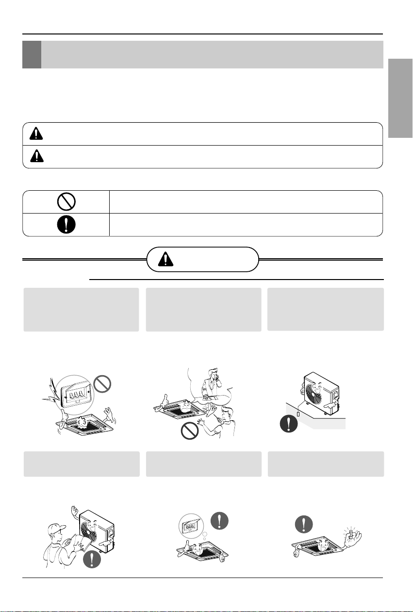
This symbol indicates the possibility of death or serious injury.
This symbol indicates the possibility of injury or damage.
WARNING
Be sure not to do.
Be sure to follow the instruction.
Safety Precautions
■ Installation
Install the panel and the cover of
control box securely.
• There is risk of fire or
electric shock.
Always install a dedicated
circuit and breaker.
• Improper wiring or
installation may cause fire or
electric shock
Use the correctly rated breaker
or fuse.
• There is risk of fire or
electric shock.
Do not use a defective or
underrated circuit breaker. Use
this appliance on a dedicated
circuit.
• There is risk of fire or
electric shock.
For electrical work, contact the
dealer, seller, a qualified
electrician, or an Authorized
Service Center.
•
Do not disassemble or repair
the product.There is r isk of
fire or electric shock.
Always ground the product.
• There is risk of fire or
electric shock.
WARNING
CAUTION
4 Cassette type Air Conditioner
Safety Precautions
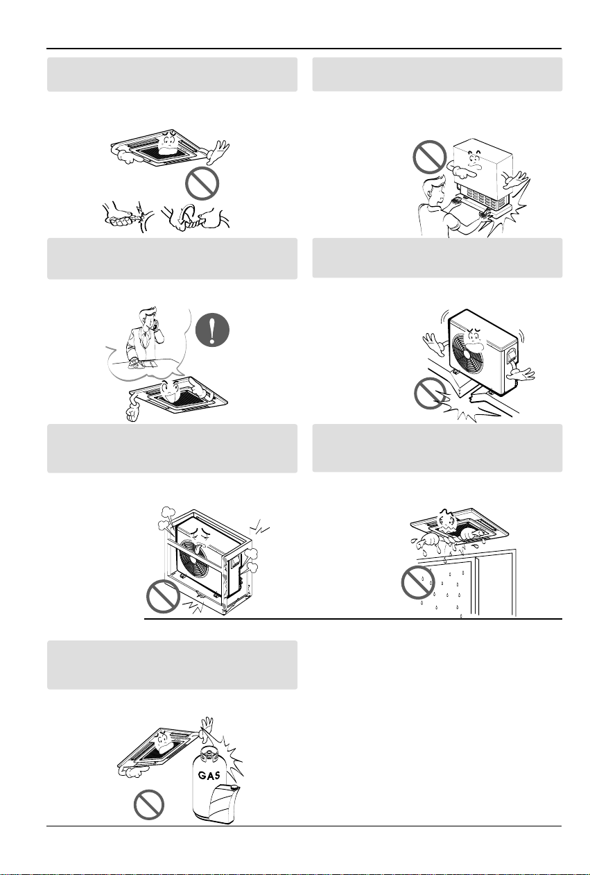
Do not modify or extend the power cable.
• There is risk of fire or electric shock.
Be cautious when unpacking and installing the
product.
•
Sharp edges could cause injury.Be especially
careful of the case edges and the fins on the
condenser and evaporator.
For installation, always contact the dealer or an
Authorized Service Center.
• There is risk of fire, electric shock, explosion,
or injury.
Do not install the product on a defective
installation stand.
• It may cause injury, accident, or damage to
the product.
Be sure the installation area does not
deteriorate with age.
•
If the base collapses, the air conditioner could fall with
it, causing property damage, product failure, and
personal injury.
Do not let the air conditioner run for a long time when
the humidity is very high and a door or a window is
left open.
• Moisture may condense and wet or damage
furniture.
Do not store or use flammable gas or combustibles
near the product.
• There is risk of fire or failure of product.
■ Operation
Gasolin
Installation Manual 5
ENGLISH
Safety Precautions
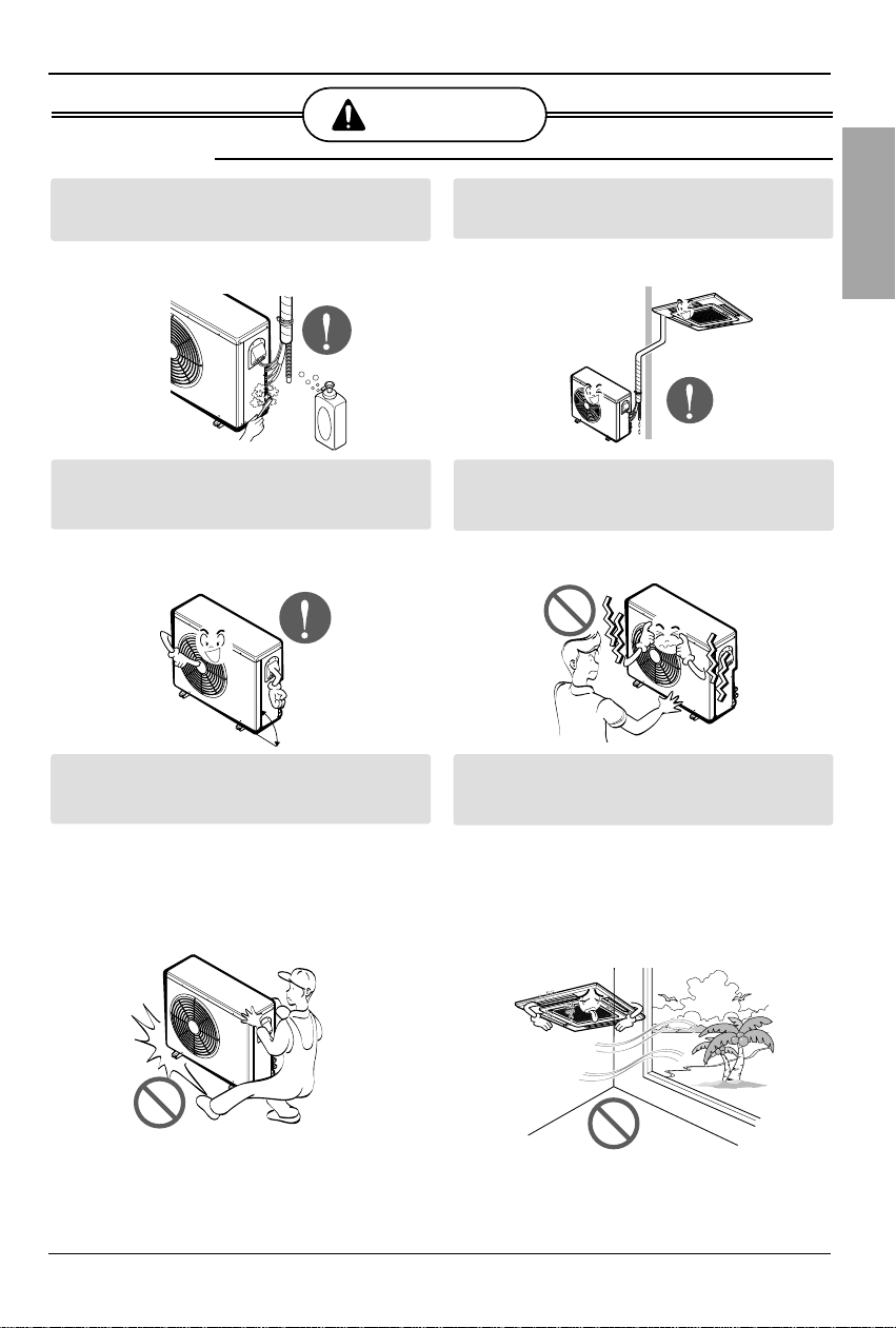
Always check for gas (refrigerant) leakage after
installation or repair of product.
• Low refrigerant levels may cause failure of
product.
Install the drain hose to ensure that water is
drained away properly.
• A bad connection may cause water leakage.
Keep level even when installing the product.
• To avoid vibration or water leakage.
Do not install the product where the noise or hot air
from the outdoor unit could damage the
neighborhoods.
• It may cause a problem for your neighbors.
Use two or more people to lift and transport the
product.
• Avoid personal injury.
Do not install the product where it will be
exposed to sea wind (salt spray) directly.
• It may cause corrosion on the product.
Corrosion, particularly on the condenser and
evaporator fins, could cause product
malfunction or inefficient operation.
CAUTION
90°
■ Installation
6 Cassette type Air Conditioner
Installation of Indoor, Outdoor Unit
Installation of Indoor, Outdoor Unit
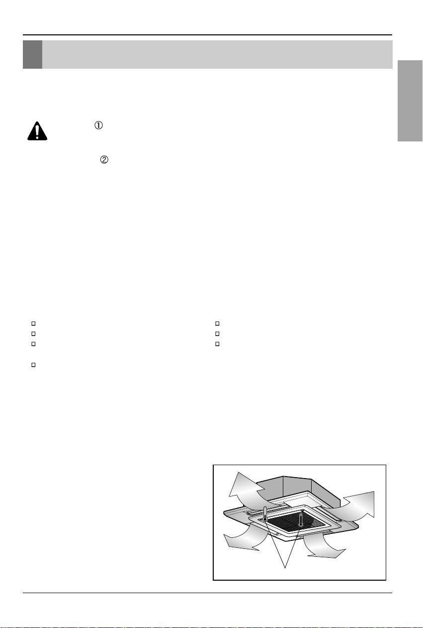
1. Indoor unit
• There should not be any heat source or
steam near the unit.
• There should not be any obstacles to
prevent the air circulation.
• A place where air circulation in the room
will be good.
• A place where drainage can be easily
obtained.
• A place where noise prevention is taken
into consideration.
• Do not install the unit near the door way.
• Ensure the spaces indicated by arrows
from the wall, ceiling, or other obstacles.
• The indoor unit must keep the
maintenance space.
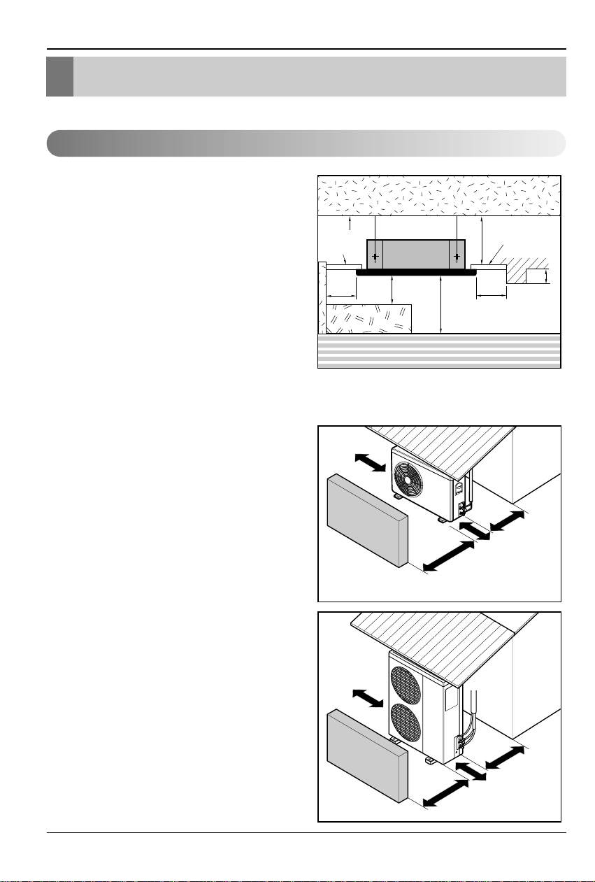
2. Outdoor unit
• If an awning is built over the unit to prevent
direct sunlight or rain exposure, be careful
that heat radiation from the condenser is
not restricted.
• There should not be any animals or plants
which could be affected by hot air
discharged.
• Ensure the spaces indicated by arrows
from the wall, ceiling, fence or other
obstacles.
Selection of the best location
Unit:cm
Ceiling
Ceiling Board
Ceiling Board
30 or more
Above 250
330 or less
100
or more
50 or
more
50 or
more
30 or less
Floor
More than
30cm
Fence or
obstacles
More than
50cm
Fence or
obstacles
Sunroof
Sunroof
More than
More than
30cm
30cm
More than 50cm
More than 70cm
More than
More than
30cm
50cm
More than 50cm
More than 100cm
Installation Manual 7
ENGLISH
Installation of Indoor, Outdoor Unit
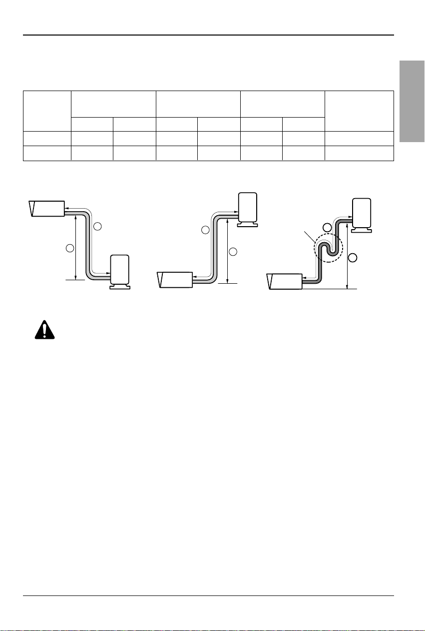
3. Piping length and the elevation
Gas Liquid Standard Max. Standard Max.
24k Btu/h
1/2"(12.7mm) 1/4"(6.35mm)
7.5(25') 30(100') 5(16') 15(50') 20(0.22 oz./ft.)
34k Btu/h
5/8"(15.88mm) 1/4"(6.35mm)
7.5(25') 35(115') 5(16') 20(66') 30(0.32 oz./ft.)
Capacity
Pipe Size
Length A(m) Elevation B(m)
*Additional
(Diameter:Ø)
refrigerant(g/m)
Outdoor unit
Indoor unit
A
B
Outdoor unit
Indoor unit
A
B
A
Oil trap
If piping length is more than 5m
Outdoor unit
Indoor unit
B
CAUTION:
• Rated performance for refrigerant line length of:7.5m
• Capacity is based on standard length and maximum allowance length is on the
basis of reliability.
• Improper refrigerant charge may result in abnormal cycle.
• Oil trap should be installed every 10 meters.
8 Cassette type Air Conditioner
• Select and mark the position for fixing bolts
and piping hole.
• Decide the position for fixing bolts slightly
tilted to the drain direction after considering
the direction of drain hose.
• Drill the hole for anchor bolt on the wall.
CAUTION:
•
This air-conditioner uses a drain pump.
• Horizontly install the unit using a
level gauge.
•
During the installation, care should be
taken not to damage electric wires.
• Thoroughly study the following installation locations:
1. In such places as restaurants and kitchens, considerable amount of oil steam and flour
adhere to the turbo fan, the fin of the heat exchanger and the drain pump, resulting in heat
exchange reduction, spraying, dispersing of water drops, drain pump malfunction, etc.
In these cases, take the following actions:
• Make sure that the ventilation fan for smoke-collecting hood on a cooking table has
sufficient capacity so that it draws oily steam which should not flow into the suction of the
air conditioner.
• Make enough distance from a cooking room to install the air conditioner in such a place
where it may not suck in oily steam.
2. Avoid installing air conditioner in such circumstances where cutting oil mist or iron powder is
in suspension in factories, etc.
3. Avoid places where inflammable gas is generated, flows in, is stored or vented.
4. Avoid places where sulfurous acid gas or corrosive gas is generated.
5. Avoid places near high frequency generators.
NOTICE
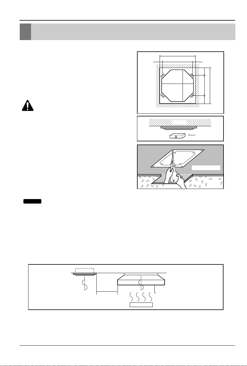
Ceiling opening dimensions and hanging bolt location
• The dimensions of the paper model for installing are the same as those of the ceiling opening dimensions.
Ceiling board
Level gauge
Ceiling
Use the ventilation fan
for smoke-collecting
hood with sufficient
capacity.
Cooking table
Air conditioner
Take enough
distance
Unit:mm
840 Unit size
840 Unit size
672 (Hanging bolt)
101.5101.5
875 (Ceiling opening)
875 (Ceiling opening)
785 (Hanging bolt)
45
45
Ceiling opening dimensions and hanging bolt location
Installation Manual 9
ENGLISH
Wall
5~7mm
Indoor Outdoor
Set screw of
paper model (4 pieces)
Paper model
for installation
Ceiling board
150mm
Adjust the same height
Ceiling board
Ceiling
Flat washer for M10
(accessory)
Keep the length of the bolt
from the bracket to 40mm
Open the ceiling board
along the outer edge of the
paper model
Flat washer for M10
(accessory)
Hanging bolt
(W3/8 or M10)
Nut
(W3/8 or M10)
Nut
(W3/8 or M10)
Spring washer
(M10)
Air Conditioner body
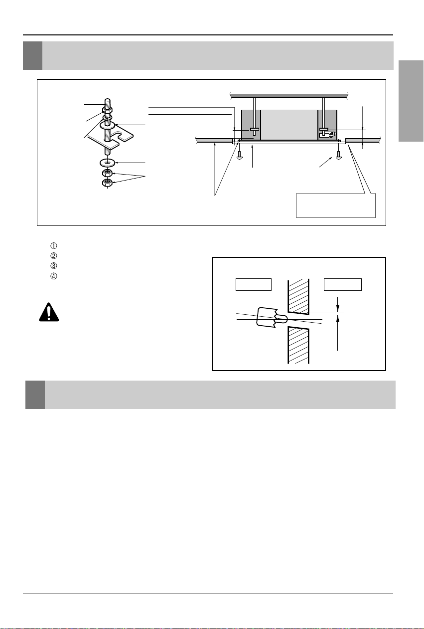
The Indoor Unit Installation
• The following parts is option.
Hanging Bolt - W 3/8 or M10
Nut - W 3/8 or M10
Spring Washer - M10
Plate Washer - M10
CAUTION:
Tighten the nut and bolt
to prevent unit falling.
• Drill the piping hole on the wall slightly tilted to the
outdoor side using a Ø 70 hole-core drill.
• Although the room temperature sensor is in the indoor unit, the remote controller should
be installed in such places away from direct sunlight and high humidity.
Installation of the remote controller
• Select places that are not splashed with water.
• Select control position after receiving customer approval.
• The room temperature sensor is built in the indoor unit.
• This remote controller equipped with liquid crystal display. If this position is higher or lower,
display is difficult to see.(The standard height is 1.2 ~ 1.5m high)
Routing of the remote controller cord
• Keep the remote controller cord away from the refrigerant piping and the drain piping.
• To protect the remote controller cord from electrical noise, place the cord at least 5cm away
from other power cables (audio equipment, television set, etc.)
• If the remote controller cord is secured to the wall, provide a trap at the top of the cord to
prevent water droplets from running.
The Indoor Unit Installation
Remote Controller Installation
10 Cassette type Air Conditioner
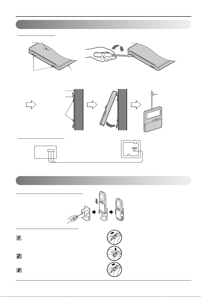
Wired Remote Control Installation
Remote Control Preparation
Remote control
box body
Cord clamp
(accessory)
Lever carefully
the box open
using a screw
driver, etc.
Front case
The lower part
Face of wall
Under plate
Screw (accessory)
Remote Controller Installation
HO
W TO MOUNT ONTO A WALL
HO
W TO INSERT BATTERIES
Remove the battery cover from the remote
controller.
• Slide the cover according to the arrow
direction.
Insert the two batteries.
• Be sure that the (+) and (-) directions are
correct.
• Be sure that both batteries are new.
Re-attach the cover.
• Slide it back into position.
• Fix the under plate on the wall
• Separate the under plate from Remote control box.
• Fix the cord clamps on the wall by
ø 3 tapping screws (accessory).
• Fix the remote control cord.
DISASSEMBLING
ELECTRICAL WIRING
Wire and make sure that terminal
numbers are matched on unit side and
remote controller side.
The maximum length of the cord is 100m.
If the length of the cord exceeds 50m,
use a wire size greater than 0.5mm
2
.
Remote controller
(Main board)
CN REMO
• Do not use rechargeable batteries,
such batteries differ from standard
dry cells in shape, dimensions, and
performance.
• Romove the batteries from the
remote controller if the air
conditioner is not going to be used
for some long time.
Installation Manual 11
ENGLISH
Wiring Connection
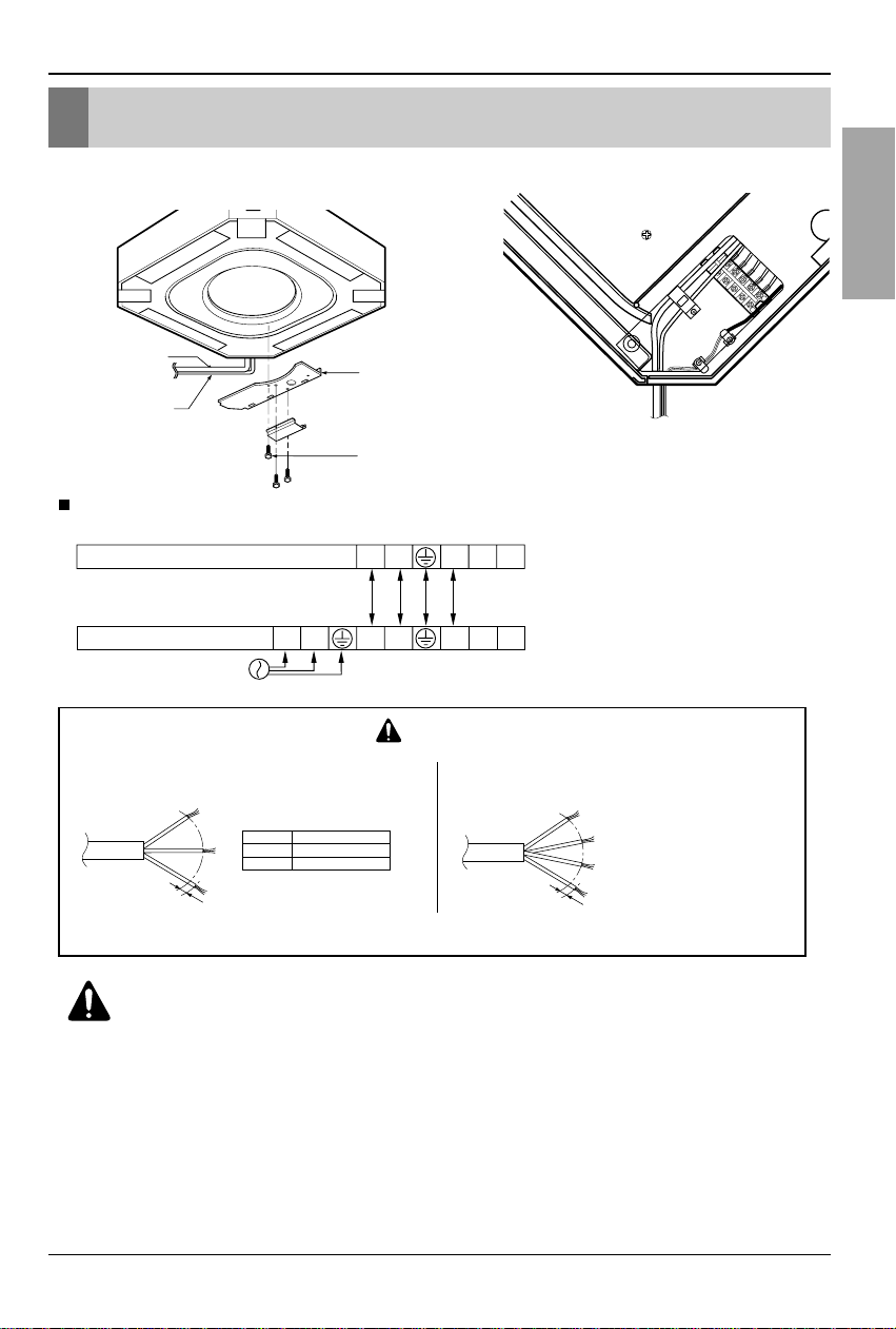
• Open the control box cover and connect the Remote controller cord and Indoor power wires.
[Air inlet side view]
Control box cover
Indoor
power cord
Remote
controller
cord
Control box cover screw
• Cooling & Heating type
The power cord connected to the outdoor unit should be
complied with the following specifications (Rubber
insulation, type H05RN-F approved by HAR or SAA).
If the supply cord is damaged, it must be replaced by a special cord or assembly available from the manufacturer of its service agent.
The connecting cable connected to the indoor and outdoor
unit should be complied with the following specifications
(Rubber insulation, type H05RN-F approved by HAR or SAA).
CAUTION
20mm
G
N
/Y
L
NORMAL
CROSS-SECTIONAL
AREA 2.1mm
2
(24k/34k)
20mm
G
N
/Y
L
Capacity
24k Btu/h
34k Btu/h
1 Phase
2.1mm
2
3.3mm
2
NORMAL CROSS-SECTIONAL AREA
24k/34k Btu/h (1Ø)
POWER
INPUT
Terminals on the indoor unit
Terminals on the outdoor unit
1(L) 2(N) 2(N) 31(L)
2(N) 3 4 51(L)
45
WARNING:
Make sure that the screws of the terminal are free from looseness.
Wiring Connection
12 Cassette type Air Conditioner
Electrical Wiring
Connecting the cable to Outdoor Unit
Wiring Connection
1. All wiring must comply with LOCAL REGULATIONS.
2. Select a power source that is capable of supplying the current required by the air conditioner.
3. Feed the power source to the unit via a distribution switch board designed for this purpose.
4.The ter minal screws inside the control box may be loose due to vibration during transport.
Check the screws for loose connection.
(Running the air conditioner with loose connection can overload and damage electrical
components.)
5. Always ground the air conditioner with a grounding wire and connector to meet the LOCAL
REGULATION.
Main power source
Switch box
Refrigerant pipe
Circuit Breaker
Use circuit breaker or time delay fuse.
1. Remove the Cover control from the unit by loosening a
screw.
Connect the wires to the terminals on the control
board individually as following.
2. Secure the cable onto the control board with the
holder (clamper).
3. Refix the cover control to the original position with the
screw.
4. Use a recongnized circuit breaker between the power
source and the unit. A disconnection device to
adequately disconnect all supply lines must be fitted.
Outdoor unit
Terminal block
Over 5mm
(0.2")
Cover control
Conduit panel
Connecting
cable
Power supply
cord
Installation Manual 13
ENGLISH
Connecting Pipes to the Indoor Unit
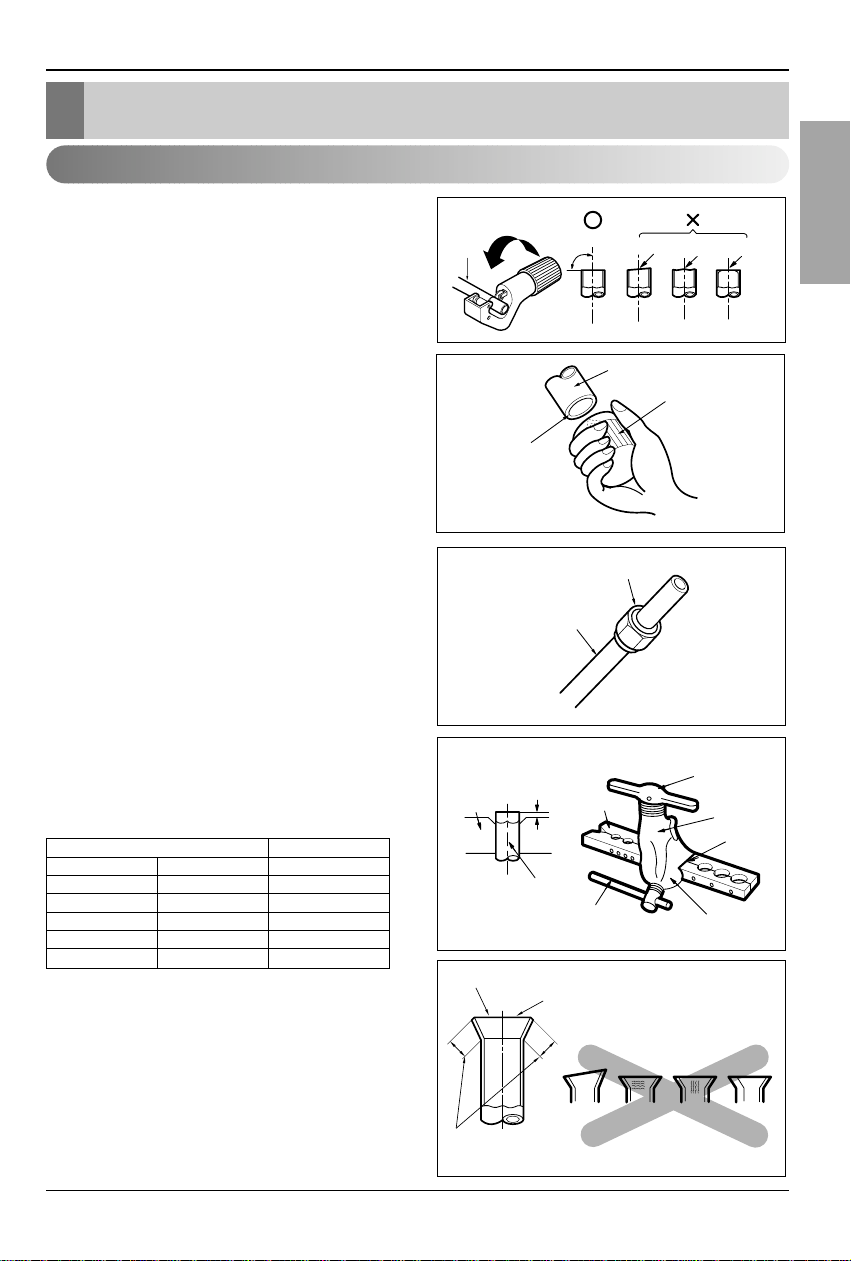
Main cause of gas leakage is defect in flaring
work. Carry out correct flaring work in the
following procedure.
1. Cut the pipes and the cable.
• Use the accessory piping kit or the pipes
purchased locally.
• Measure the distance between the indoor
and the outdoor unit.
• Cut the pipes a little longer than measured
distance.
•
Cut the cable 1.5m longer than the pipe
length.
2. Burrs removal
• Completely remove all burrs from the cut
cross section of pipe/tube.
•
Put the end of the copper tube/pipe to
downward direction as you remove burrs in
order to avoid to let burrs drop in the tubing.
3. Putting nut on
• Remove flare nuts attached to indoor and
outdoor units, than put them on pipe/tube
having completed burr removal.
(Not possible to put them on after flaring work)
4. Flaring work
•
Carry out flaring work using dedicated
flaring tool for R-410A as shown below.
Firmly hold copper tube in a bar(or die) as
indicated dimension in the table above.
5. Check
• Compare the flared work with figure below.
• If flare is noted to be defective, cut off the
flared section and do flaring work again.
Copper
tube
90°
Slanted Uneven Rough
Pipe
Reamer
Point down
Flare nut
Copper tube
Bar
Copper pipe
Clamp handle
Red arrow mark
Cone
Yoke
Handle
Bar
"A"
Inclined
Inside is shining without scratches
Smooth all round
Even length
all round
Surface
damaged
Cracked Uneven
thickness
= Improper flaring =
Connecting Pipes to the Indoor Unit
Preparation of Piping
Outside diameter A
mm inch mm
Ø6.35 1/4 1.0~1.5
Ø9.52 3/8 1.0~1.5
Ø12.7 1/2 1.0~1.5
Ø15.88 5/8 1.0~1.5
Ø19.05 3/4 2.0~3.0
14 Cassette type Air Conditioner
Connecting Pipes to the Indoor Unit
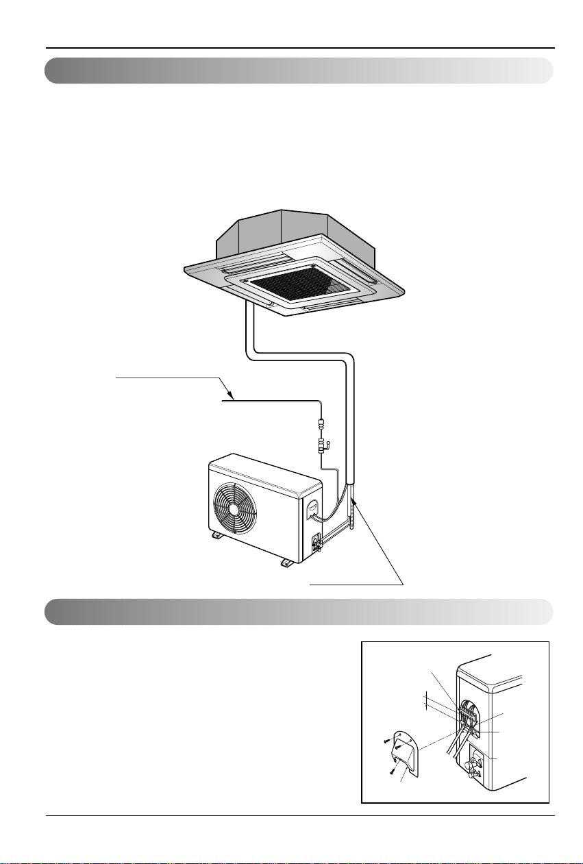
1. Form the piping according to its routing. Avoid
bending and bending back the same piping point
more than three times. (This will result in
hardening the pipe.)
2. After deforming the piping, align centers of the
union fitting of the indoor unit and the piping,
and tighten them firmly with wrenches.
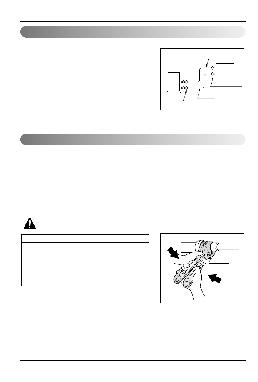
3. Connect pipe to the service valve or ball valve
which is located below the outdoor unit.
4. After completing the piping connection, be sure
to check if there is gas leakage in indoor and
outdoor connection.
After completing the piping connection, execute
vacuum drying for the connecting piping and the
indoor unit.
The vacuum drying must be carried out using
the service ports of both the liquid and gas side
valves.
CAUTION:
Use two wrenches and
tighten with regular torque.
Outdoor
unit
Liquid side
Flare connection
Flare connection
Gas side
Indoor
unit
Union
Flare nut fastening torque
Ø6.35mm 1.8kg.m
Ø9.52mm 2.7kg.m
Ø12.7mm 3.7kg.m
Ø15.88mm 4.7kg.m
Ø19.05mm 5.7kg.m
Piping Connection
Vacuum drying
Installation Manual 15
ENGLISH
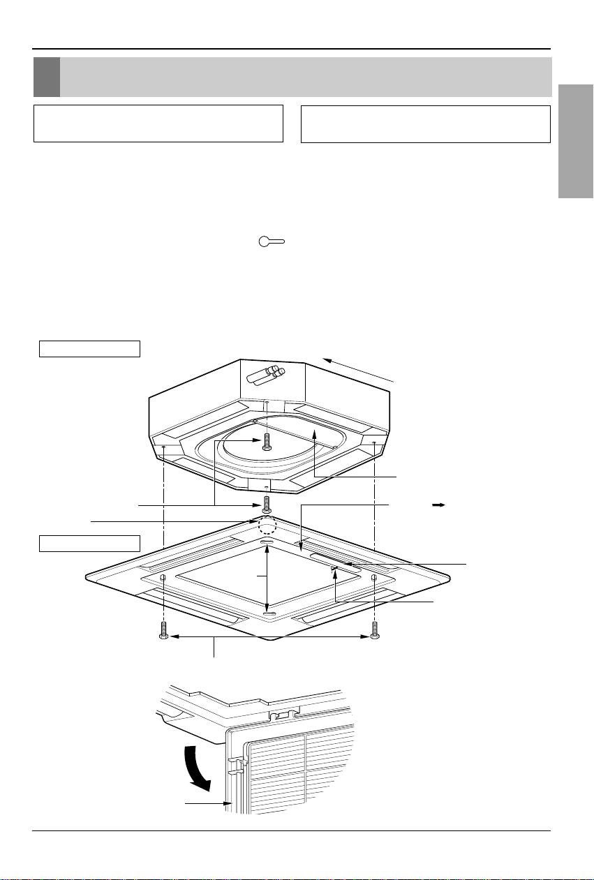
Installation to Decorative Panel
1.Temporarily fix two decorative panel fixing screws (hexagon M5 screw) on the unit body.
(Tighten by amount 10mm in length.)
The fixing screws (hexagon M5 screw) are included the decorative panel box.
2. Remove the air inlet grille from the decorative panel.(Remove the hook for the air inlet grille
cord.)
3. Hook the decorative panel key hole ( ) on the screws fixed in step above, and slide the
panel so that the screws reach the key hole edge.
4. Retighten completely two temporarily fixed screws and other two screws. (Total 4 screws)
5. Connect the louver motor connector and display connector.
6. After tightening these screws, install the air inlet grille (including the air filter).
Decorative panel fixing screws
(hexagon M5 screws)
Temporally fitting at 2 places
(Tightening about 10mm)
Install the panel after
making sure that the
piping side of the unit body
matches the piping
indication of the decorative
panel
Control box cover
Piping side
Inlet GrilleInlet GrilleInlet Grille
Inlet GrilleInlet Grille
Louver motor
Decorative panel fixing screws
(Hexagon M5 screw)
The arrow ( ) should point
to the side where the pipes are.
Air conditioner unit
Decorative panel
Key holes
Display
Lead wire for
louver motor and
display
The decorative panel has its installation
direction.
Before installing the decorative panel,
always remove the paper template.
Installation to Decorative Panel
16 Cassette type Air Conditioner
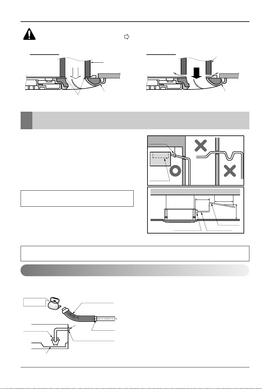
Indoor Unit Drain Piping
CAUTION:
Install certainly the decorative panel.
Cool air leakage causes sweating.
Water drops fall.
• Drain piping must have down-slope (1/50 to
1/100): be sure not to provide up-and-down
slope to prevent reversal flow.
• During drain piping connection, be careful
not to exert extra force on the drain port on
the indoor unit.
• The outside diameter of the drain
connection on the indoor unit is 32mm.
• Be sure to execute heat insulation on the
drain piping.
• Install the drain raising pipes at a right
angle to the indoor unit and no more than
300mm from the unit.
The air conditioner uses a drain pump to drain water.
Use the following procedure to test the drain pump operation:
• Connect the main drain pipe to the exterior and leave
it provisionally until the test comes to an end.
• Feed water to the flexible drain hose and check the
piping for leakage.
• Be sure to check the drain pump for normal
operating and noise when electrical wiring is
complete.
• When the test is complete, connect the flexible drain
hose to the drain port on the indoor unit.
Air conditioner
unit
Ceiling
board
Decorative panel
Decorative
panel
Fit the insulator (this part) and
be careful for cool air leakage
Good example
Air
Cool air leakage
(no good)
Bad example
Ceiling
board
Air conditioner unit
Maintenance
drain port
Upward
routing
not allowed
Pipe clamp
Indoor unit
700 or less
1 -1.5m
300mm or less
Clamp metal(attached) Drain hose(attached)
Drain raising pipe
Feed water
Drain Pump
Drain pan
Flexible drain hose
(accessory)
Main
drain pipe
Glue the joint
Drain
port
Drain hose connection
Use the clip (accessory)
Piping material: Polyvinyl chloride pipe VP-25
and pipe fittings
Heat insulation material: Polyethylene foam with thickness more than 8 mm.
Drain test
Indoor Unit Drain Piping
Installation Manual 17
ENGLISH
Indoor Unit Drain Piping
HEAT INSULATION
1. Use the heat insulation material for the refrigerant piping which has an excellent heatresistance (over 120°C).
2. Precautions in high humidity
circumstance:
This air conditioner has been tested
according to the "KS Standard
Conditions with Mist" and confirmed
that there is not any default.However, if
it is operated for a long time in high
humid atmosphere (dew point
temperature: more than 23°C), water
drops are liable to fall.In this case, add
heat insulation material according to the
following procedure:
• Heat insulation material to be
prepared... Adiabatic glass wool with
thickness 10 to 20mm.
• Stick glass wool on all air conditioners
that are located in ceiling atmosphere.
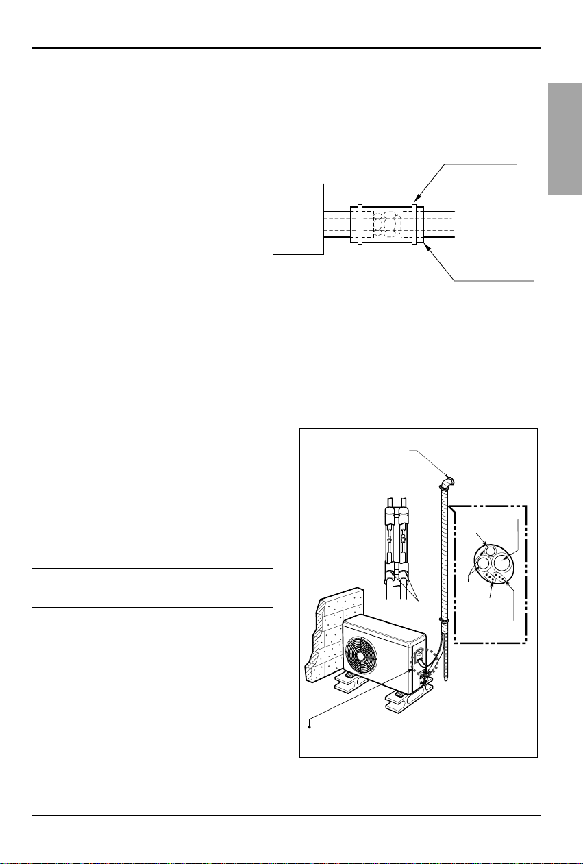
FORM THE PIPINGS
1.Wrap the connecting portion of indoor
unit with the Insulation material and
secure it with two Plastic Bands. (for the
right pipings)
• If you want to connect an additional drain hose,
the end of the drain-outlet should keep distance
from the ground. (Do not dip it into water, and fix
it on the wall to avoid swinging in the wind.)
2.Tape the Pipings, drain hose and
Connecting Cable from bottom to top.
3. Form the pipings gathered by taping
along the exterior wall and fix it onto the
wall by saddle or equivalent.
• In addition to the normal heat insulation
(thickness: more than 8mm) for refrigerant
piping (gas piping: thick piping) and drain
piping, add further 10mm to 30mm thickness
material.
Indoor unit
Thermal insulator
(accessory)
Fastening band
(accessory)
Refrigerant piping
In case of the Outdoor unit being installed
below position of the Indoor unit.
Seal a small opening
around the pipings
with gum type sealer.
Taping
Drain hose
Pipings
Plastic Band
Trap is required to prevent water from entering
into electrical parts.
Connecting
cable
Power supply
cord
18 Cassette type Air Conditioner
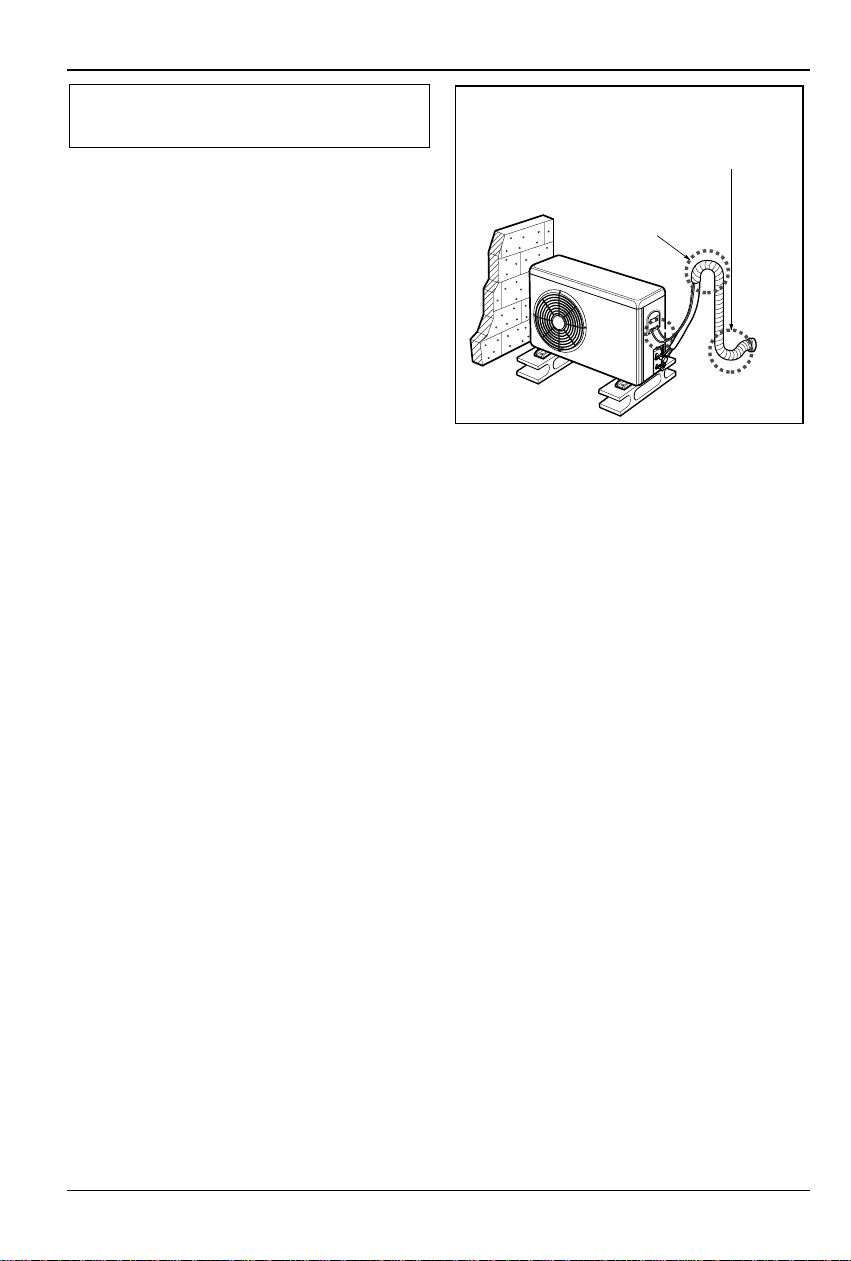
Indoor Unit Drain Piping
2.Tape the Pipings and Connecting cable
from bottom to top.
3. Form the pipings gathered by taping along
the exterior wall, and make the trap prevent
water from entering into the room.
4. Fix the pipings onto the wall by saddle or
equivalent.
In case of the Outdoor Unit being installed
above position of the Indoor Unit.
Seal a small opening
around the pipings
with gum type sealer.
Trap
Test running
Installation Manual 19
ENGLISH
1. PRECAUTIONS IN TEST RUN
• The initial power supply must provide at least 90% of the rated voltage.
Otherwise, the air conditioner should not be operated.
CAUTION For test run, carry out the cooling operation firstly even during heating
season. If heating operation is carried out firstly, it leads to the trouble
of compressor.Then attention must be paid.
Carry out the test run more than 5 minutes without fail.
(Test run will be cancelled 18 minutes later automatically)
• The test run is started by pressing the room temperature checking button and down timer
button for 3 seconds at the same time.
• To cancel the test run, press any button.
CHECK THE FOLLOWING ITEMS WHEN INSTALLATION IS COMPLETE
• After completing work, be sure to measure and record trial run properties, and store measured
data, etc.
• Measuring items are room temperature, outside temperature, suction temperature, blow out
temperature, wind velocity, wind volume, voltage, current, presence of abnormal vibration and
noise, operating pressure, piping temperature, compressive pressure.
• As to the structure and appearance, check following items.
2. Connection of power supply
1. Connect the power supply cord to the independent power supply.
• Circuit breaker is required.
2. Operate the unit for fifteen minutes or more.
3. Evaluation of the performance
1. Measure the temperature of the
intake and discharge air.
2. Ensure the difference between the
intake temperature and the discharge
one is more than 8°C (Cooling) or
reversely (Heating).
Is the circulation of air adequate?
Is the draining smooth?
Is the heat insulation complete
(refrigerant and drain piping)?
Is there any leakage of refrigerant?
Is the remote controller switch operated?
Is there any faulty wiring?
Are not terminal screws loosened?
M4......118N.cm{12kgf.cm} M5......196N.cm{20kgf.cm}
M6......245N.cm{25kgf.cm} M8......588N.cm{60kgf.cm}
Test running
Thermometer
20 Cassette type Air Conditioner
CAUTION: After the confirmation of the above conditions, prepare the wiring
as follows:
1) Never fail to have an individual power specialized for the air conditioner. As
for the method of wiring, be guided by the circuit diagram pasted on the
inside of control box cover.
2) Provide a circuit breaker switch between power source and the unit.
3) The screw which fasten the wiring in the casing of electrical fittings are
liable to come loose from vibrations to which the unit is subjected during
the course of transportation. Check them and make sure that they are all
tightly fastened. (If they are loose, it could give rise to burn-out of the
wires.)
4) Specification of power source
5) Confirm that electrical capacity is sufficient.
6) Be sure that the starting voltage is maintained at more than 90 percent of
the rated voltage marked on the name plate.
7) Confirm that the cable thickness is as specified in the power sources
specification.
(Particularly note the relation between cable length and thickness.)
8) Never fail to equip a leakage breaker where it is wet or moist.
9) The following troubles would be caused by voltage drop-down.
• Vibration of a magnetic switch, damage on the contact point there of, fuse
breaking, disturbance to the normal function of a overload protection device.
• Proper starting power is not given to the compressor.
HAND OVER
Teach the customer the operation and maintenance procedures, using the operation manual
(air filter cleaning, temperature control, etc.).
Test r unning
Installation Manual 21
ENGLISH
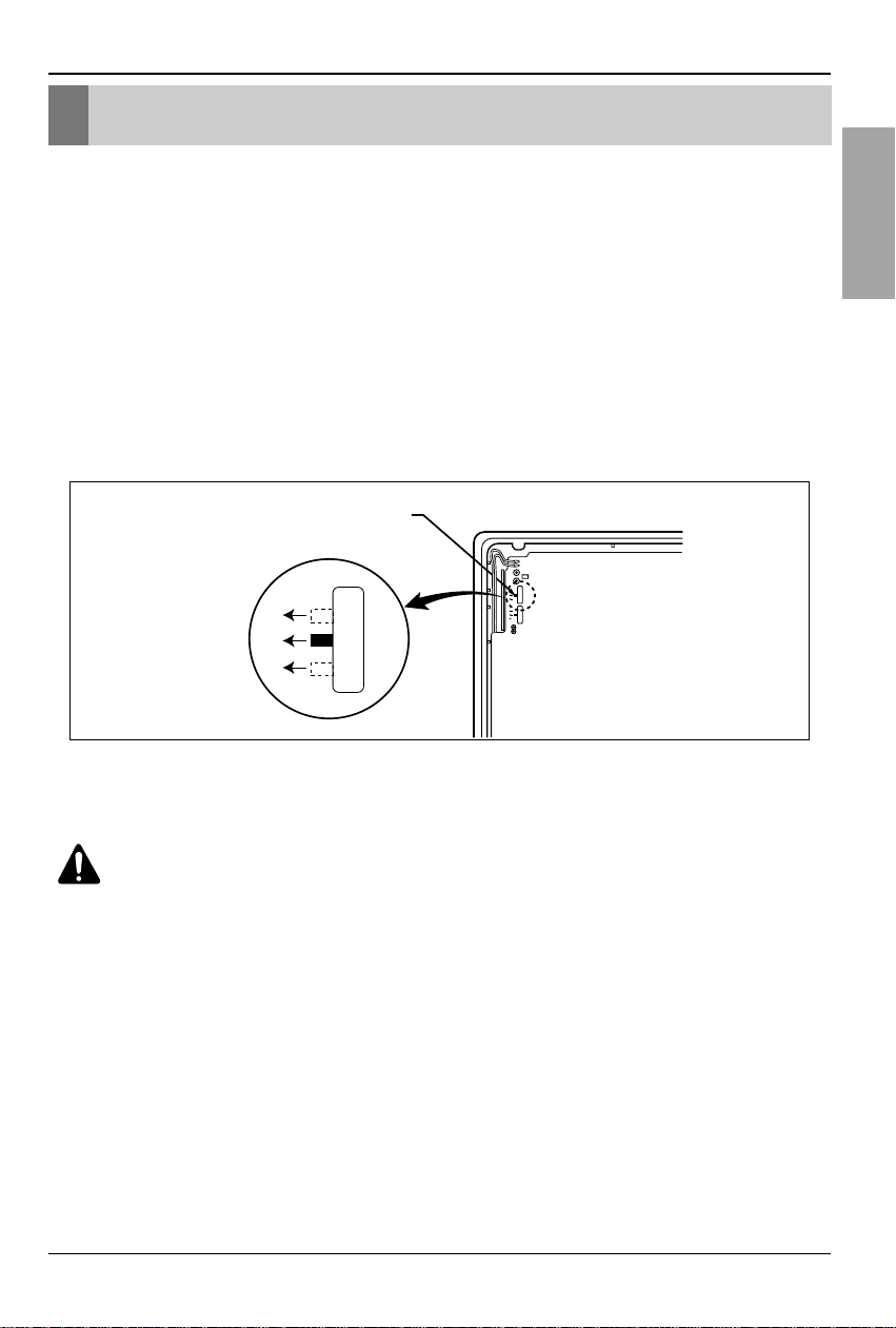
1.Two Thermistor System
(1) Open the rear cover of the wired remote-controller to set the mode.
(2) Select one of three selectable modes as follows.
• Position 1:The room themperature is controlled by the thermistor of the wired remotecontroller, control the temperature according to the position of wired remotecontroller.
• Position 2:The room temperature is controlled by the thermistor of the main body.
• Position 3:The room temperature is controlled by lower temperature between the
temperature of main body and of remote-controller sensor.
(3) Move the slide switch to set position.
(4) Close the rear cover and check if it works normally.
CAUTIO
N
:
• Select the position after counselling with a customer.
• In case of cooling mode, room temperature is controlled by the main body sensor.
• To control the room temperature by a wired remote controller, install controller(room
temp. sensor) to sense the temperature more accurately.
• Manufactured in the position 3.
Optional Operation
Optional Operation
Slide switch for 2 Thermistor
1
2
3
1
2
3
1
2
3
22 Cassette type Air Conditioner
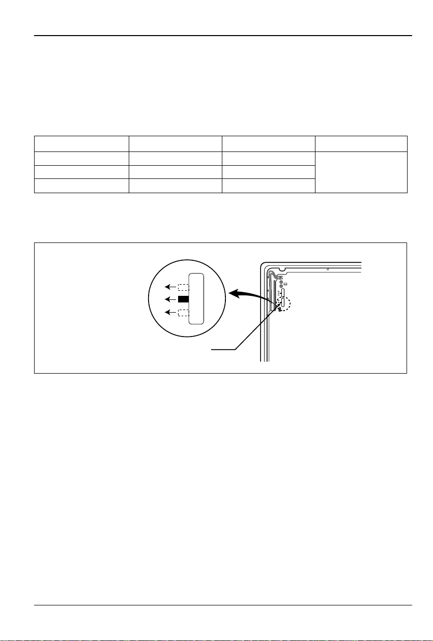
2. Adjusting air volume to the height of ceiling
You can choose the RPM(or air volume) of indoor motor according to the height of ceiling to
supply the comfortable atmosphere to consumers.
Procedure
1. Choose the selectable position in the table after measuring the height of ceiling.
2. In the case of changing the height as "high" or "low", open the rear cover of the wired remotecontroller.
3. Move the slide switch to the set position.
4. Close the rear cover and check if it works normally.
Optional Operation
Ceiling height Mode of slide switch Change of air volume Remark
more than 3.3m High Ceiling Increasing
2.7~3.3m Standard -
Manufactured in
less than 2.7m Low Ceiling Decreasing
standard mode
1
2
3
Slide switch for ceiling height
1
2
3
1
2
3
 Loading...