


ENGLISH FRANÇAIS ESPAÑOL
LG Casstte Type
Air Conditioner
INSTALLATION MANUAL
LG
website http://www.lgservice.com
IMPORTANT
• Please read this installation manual completely before
installing the product.
• Installation work must be performed in accordance with
the national wiring standards by authorized personnel
only.
• Please retain this installation manual for future reference
after reading it thoroughly.

2 Cassette type Air Conditioner
Cassette Type Air Conditioner Installation Manual
TABLE OF CONTENTS
Safety Precautions .....3
Installation of Indoor,
Outdoor unit................6
Ceiling opening
dimensions and hanging
bolt location
..................8
The indoor unit
installation...................9
Remote controller
installation...................9
Wiring connection ....11
Connecting Pipes to
the Indoor Unit..........13
Installation of
decorative panel .......15
Indoor unit drain piping
....................................16
Test running..............19
Optional operation....21
•
Connecting cable
• Four Type "A" Screw
• Hanging Bolt
(W 3/8 or M10 length 650mm)
• Pipes: Gas side
Liquid side
• Insulated drain hose
• Additional Drain hose
(Inner Dia.............32mm)
•
Level
•
Screw driver
•
Electric drill
•
Hole core drill (ø70mm)
• Flaring Tools set
• Torque Wrenches
• Hexagonal Wrench (4mm, 5mm)
• Gas-leak detector
•
Owner’s Manual
•
Thermometer
Installation
Requirements
Required Parts Required T ools
Safety Precautions
Installation Manual 3
ENGLISH
To prevent injury to the user or other people and proper ty damage, the following instructions
must be followed.
■
Incorrect operation due to ignoring instruction will cause harm or damage. The seriousness
is classified by the following indications.
■ Meanings of symbols used in this manual are as shown below.
This symbol indicates the possibility of death or serious injury.
This symbol indicates the possibility of injury or damage.
WARNING
Be sure not to do.
Be sure to follow the instruction.
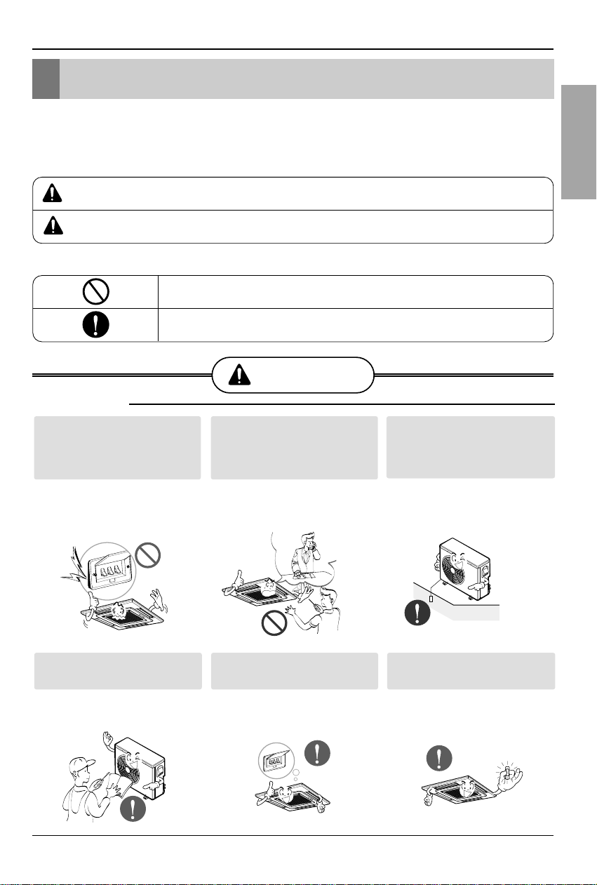
Safety Precautions
■ Installation
Install the panel and the cover of
control box securely.
• There is risk of fire or
electric shock.
Always install a dedicated
circuit and breaker.
• Improper wiring or
installation may cause fire or
electric shock
Use the correctly rated breaker
or fuse.
• There is risk of fire or
electric shock.
Do not use a defective or
underrated circuit breaker. Use
this appliance on a dedicated
circuit.
• There is risk of fire or
electric shock.
For electrical work, contact the
dealer, seller, a qualified
electrician, or an Authorized
Service Center.
•
Do not disassemble or repair
the product.There is r isk of
fire or electric shock.
Always ground the product.
• There is risk of fire or
electric shock.
WARNING
CAUTION
4 Cassette type Air Conditioner
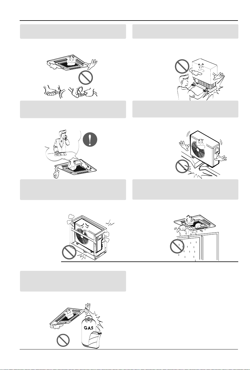
Safety Precautions
Do not modify or extend the power cable.
• There is risk of fire or electric shock.
Be cautious when unpacking and installing the
product.
•
Sharp edges could cause injury.Be especially
careful of the case edges and the fins on the
condenser and evaporator.
For installation, always contact the dealer or an
Authorized Service Center.
• There is risk of fire, electric shock, explosion,
or injury.
Do not install the product on a defective
installation stand.
• It may cause injury, accident, or damage to
the product.
Be sure the installation area does not
deteriorate with age.
•
If the base collapses, the air conditioner could fall with
it, causing property damage, product failure, and
personal injury.
Do not let the air conditioner run for a long time when
the humidity is very high and a door or a window is
left open.
• Moisture may condense and wet or damage
furniture.
Do not store or use flammable gas or combustibles
near the product.
• There is risk of fire or failure of product.
■ Operation
Gasolin
Installation Manual 5
ENGLISH
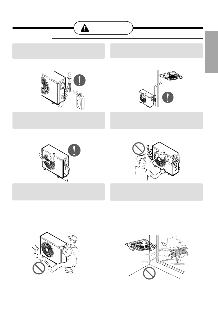
Safety Precautions
Always check for gas (refrigerant) leakage after
installation or repair of product.
• Low refrigerant levels may cause failure of
product.
Install the drain hose to ensure that water is
drained away properly.
• A bad connection may cause water leakage.
Keep level even when installing the product.
• To avoid vibration or water leakage.
Do not install the product where the noise or hot air
from the outdoor unit could damage the
neighborhoods.
• It may cause a problem for your neighbors.
Use two or more people to lift and transport the
product.
• Avoid personal injury.
Do not install the product where it will be
exposed to sea wind (salt spray) directly.
• It may cause corrosion on the product.
Corrosion, particularly on the condenser and
evaporator fins, could cause product
malfunction or inefficient operation.
CAUTION
90°
■ Installation
6 Cassette type Air Conditioner
Installation of Indoor, Outdoor Unit
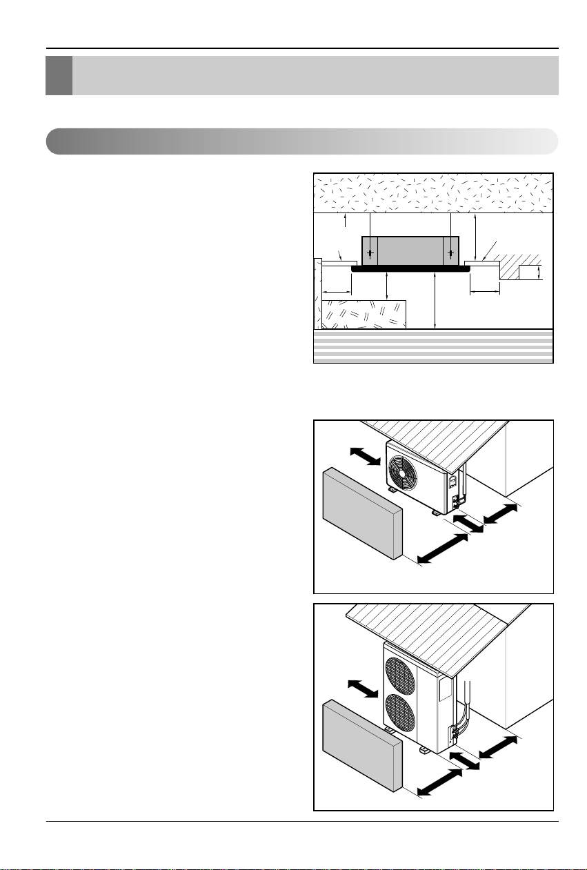
Installation of Indoor, Outdoor Unit
1. Indoor unit
• There should not be any heat source or
steam near the unit.
• There should not be any obstacles to
prevent the air circulation.
• A place where air circulation in the room
will be good.
• A place where drainage can be easily
obtained.
• A place where noise prevention is taken
into consideration.
• Do not install the unit near the door way.
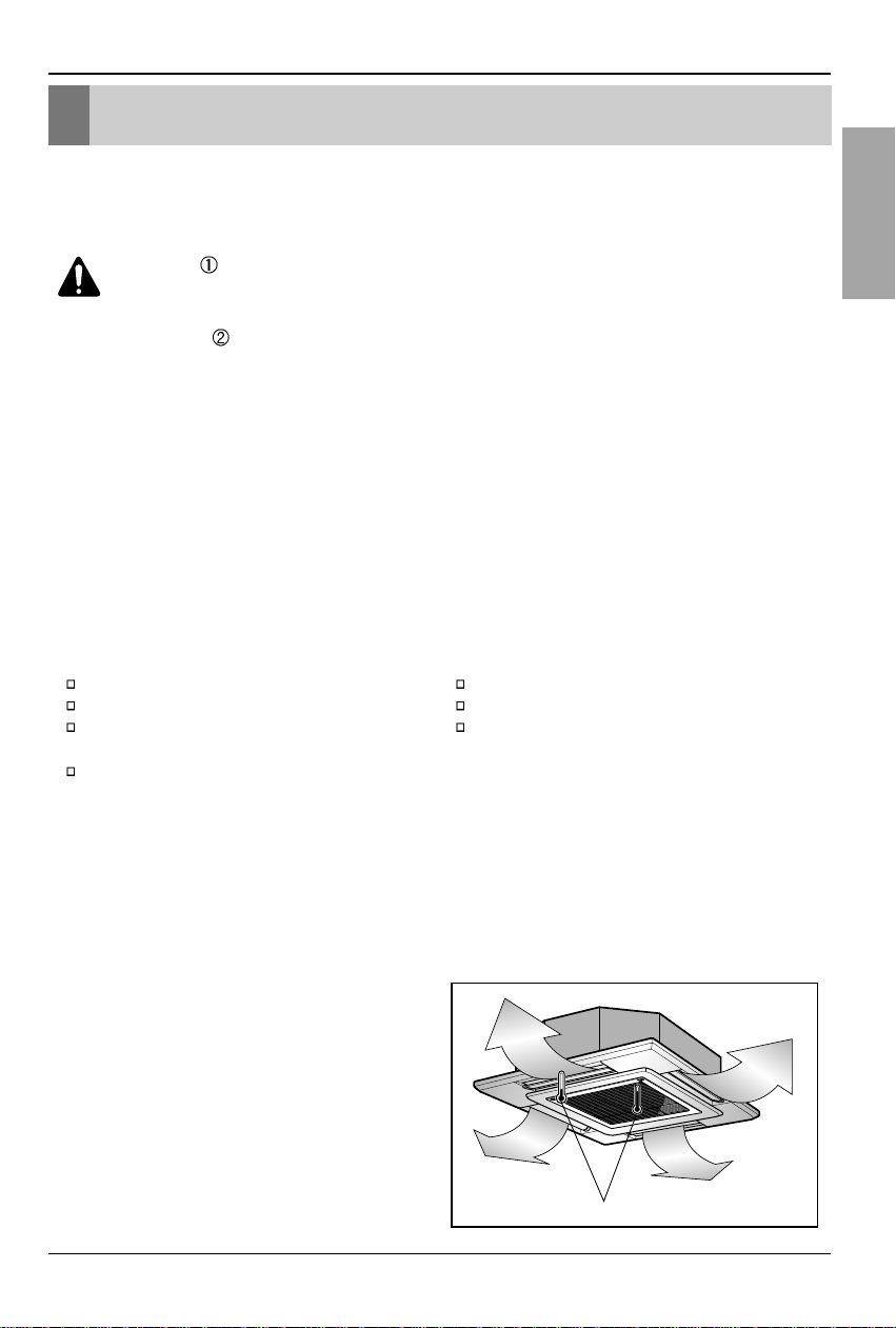
• Ensure the spaces indicated by arrows
from the wall, ceiling, or other obstacles.
• The indoor unit must keep the
maintenance space.
2. Outdoor unit
• If an awning is built over the unit to prevent
direct sunlight or rain exposure, be careful
that heat radiation from the condenser is
not restricted.
• There should not be any animals or plants
which could be affected by hot air
discharged.
• Ensure the spaces indicated by arrows
from the wall, ceiling, fence or other
obstacles.
Selection of the best location
Unit:cm
Ceiling
Ceiling Board
Ceiling Board
30 or more
Above 250
330 or less
100
or more
50 or
more
50 or
more
30 or less
Floor
More than
30cm
Fence or
obstacles
More than
50cm
Fence or
obstacles
Sunroof
Sunroof
More than
More than
30cm
30cm
More than 50cm
More than 70cm
More than
More than
30cm
50cm
More than 50cm
More than 100cm
Installation Manual 7
ENGLISH
Installation of Indoor, Outdoor Unit
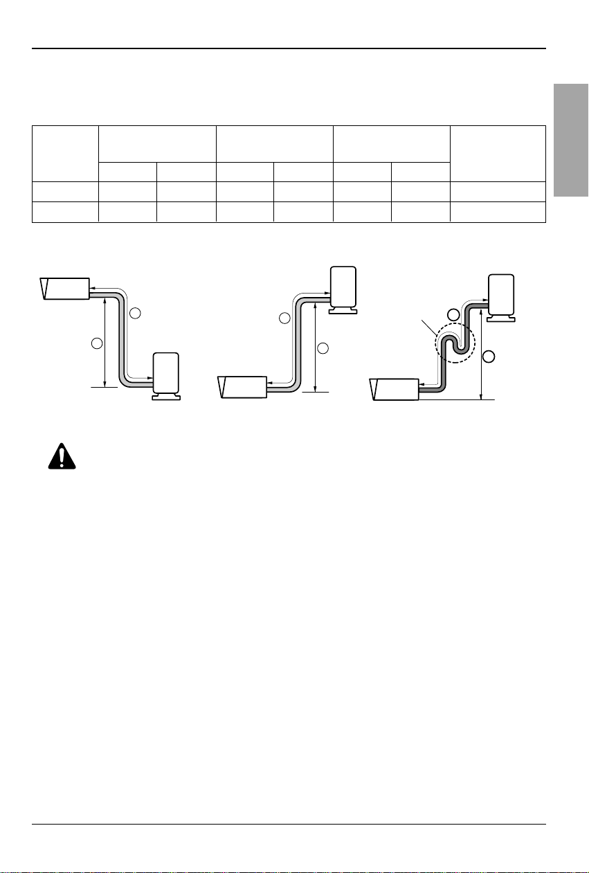
3. Piping length and the elevation
Gas Liquid Standard Max. Standard Max.
24k Btu/h
1/2"(12.7mm) 1/4"(6.35mm)
7.5(25') 30(100') 5(16') 15(50') 20(0.22 oz./ft.)
34k Btu/h
5/8"(15.88mm) 1/4"(6.35mm)
7.5(25') 35(115') 5(16') 20(66') 30(0.32 oz./ft.)
Capacity
Pipe Size
Length A(m) Elevation B(m)
*Additional
(Diameter:Ø)
refrigerant(g/m)
Outdoor unit
Indoor unit
A
B
Outdoor unit
Indoor unit
A
B
A
Oil trap
If piping length is more than 5m
Outdoor unit
Indoor unit
B
CAUTION:
• Rated performance for refrigerant line length of:7.5m
• Capacity is based on standard length and maximum allowance length is on the
basis of reliability.
• Improper refrigerant charge may result in abnormal cycle.
• Oil trap should be installed every 10 meters.
8 Cassette type Air Conditioner
• Select and mark the position for fixing bolts
and piping hole.
• Decide the position for fixing bolts slightly
tilted to the drain direction after considering
the direction of drain hose.
• Drill the hole for anchor bolt on the wall.
CAUTION:
•
This air-conditioner uses a drain pump.
• Horizontly install the unit using a
level gauge.
•
During the installation, care should be
taken not to damage electric wires.
• Thoroughly study the following installation locations:
1. In such places as restaurants and kitchens, considerable amount of oil steam and flour
adhere to the turbo fan, the fin of the heat exchanger and the drain pump, resulting in heat
exchange reduction, spraying, dispersing of water drops, drain pump malfunction, etc.
In these cases, take the following actions:
• Make sure that the ventilation fan for smoke-collecting hood on a cooking table has
sufficient capacity so that it draws oily steam which should not flow into the suction of the
air conditioner.
• Make enough distance from a cooking room to install the air conditioner in such a place
where it may not suck in oily steam.
2. Avoid installing air conditioner in such circumstances where cutting oil mist or iron powder is
in suspension in factories, etc.
3. Avoid places where inflammable gas is generated, flows in, is stored or vented.
4. Avoid places where sulfurous acid gas or corrosive gas is generated.
5. Avoid places near high frequency generators.
NOTICE
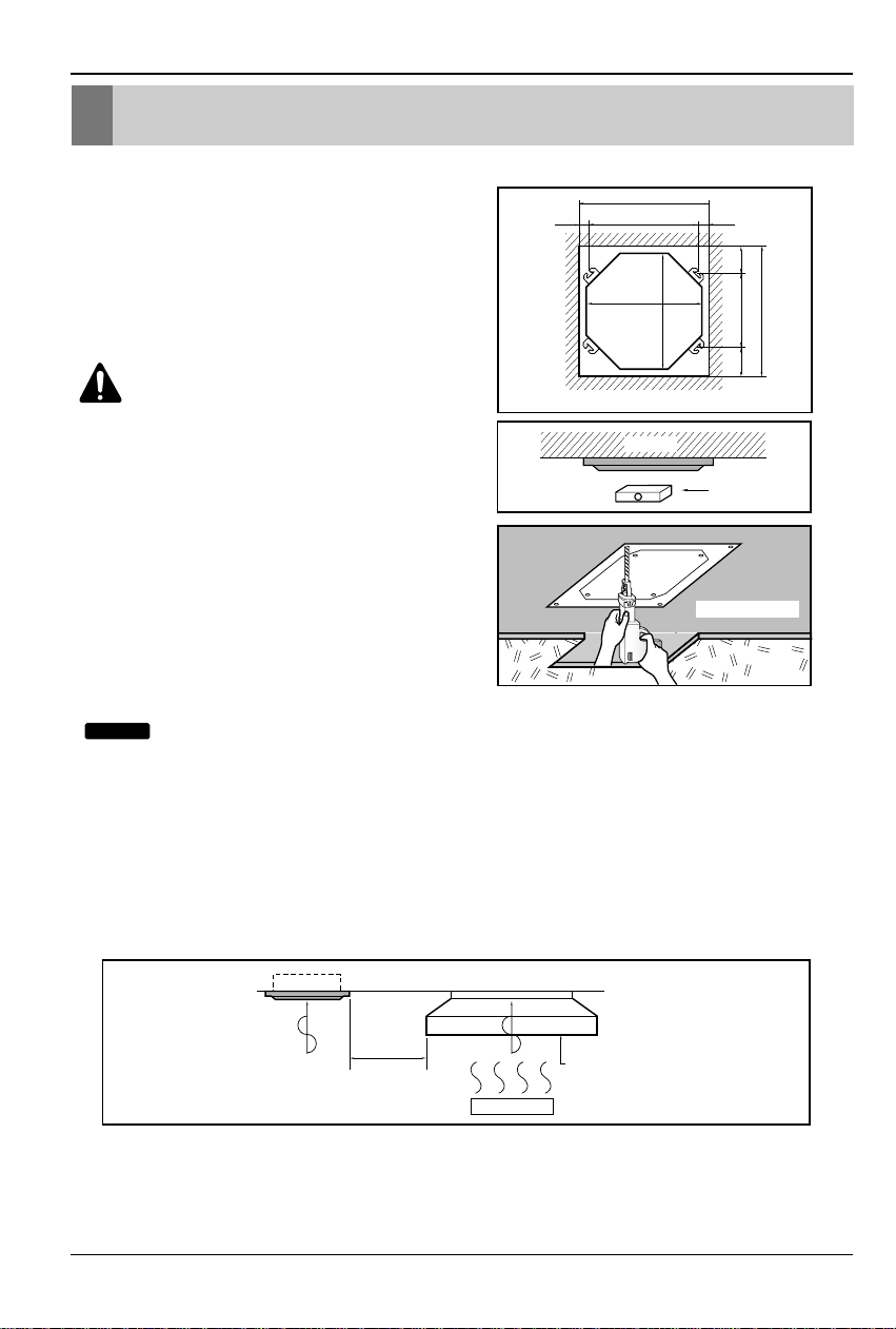
Ceiling opening dimensions and hanging bolt location
• The dimensions of the paper model for installing are the same as those of the ceiling opening dimensions.
Ceiling board
Level gauge
Ceiling
Use the ventilation fan
for smoke-collecting
hood with sufficient
capacity.
Cooking table
Air conditioner
Take enough
distance
Unit:mm
840 Unit size
840 Unit size
672 (Hanging bolt)
101.5101.5
875 (Ceiling opening)
875 (Ceiling opening)
785 (Hanging bolt)
45
45
Ceiling opening dimensions and hanging bolt location
Installation Manual 9
ENGLISH
Wall
5~7mm
Indoor Outdoor
Set screw of
paper model (4 pieces)
Paper model
for installation
Ceiling board
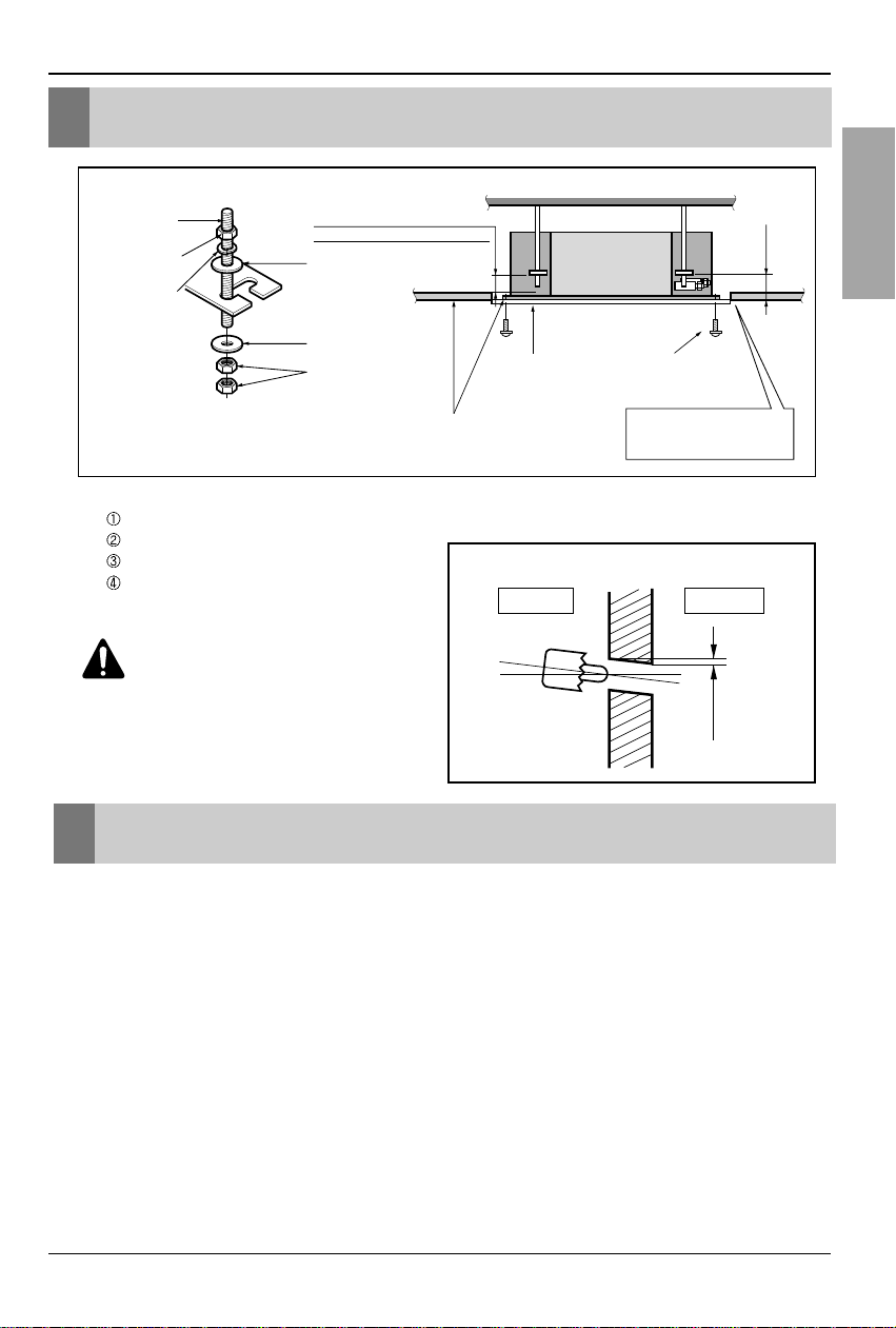
150mm
Adjust the same height
Ceiling board
Ceiling
Flat washer for M10
(accessory)
Keep the length of the bolt
from the bracket to 40mm
Open the ceiling board
along the outer edge of the
paper model
Flat washer for M10
(accessory)
Hanging bolt
(W3/8 or M10)
Nut
(W3/8 or M10)
Nut
(W3/8 or M10)
Spring washer
(M10)
Air Conditioner body
The Indoor Unit Installation
• The following parts is option.
Hanging Bolt - W 3/8 or M10
Nut - W 3/8 or M10
Spring Washer - M10
Plate Washer - M10
CAUTION:
Tighten the nut and bolt
to prevent unit falling.
• Drill the piping hole on the wall slightly tilted to the
outdoor side using a Ø 70 hole-core drill.
• Although the room temperature sensor is in the indoor unit, the remote controller should
be installed in such places away from direct sunlight and high humidity.
Installation of the remote controller
• Select places that are not splashed with water.
• Select control position after receiving customer approval.
• The room temperature sensor is built in the indoor unit.
• This remote controller equipped with liquid crystal display. If this position is higher or lower,
display is difficult to see.(The standard height is 1.2 ~ 1.5m high)
Routing of the remote controller cord
• Keep the remote controller cord away from the refrigerant piping and the drain piping.
• To protect the remote controller cord from electrical noise, place the cord at least 5cm away
from other power cables (audio equipment, television set, etc.)
• If the remote controller cord is secured to the wall, provide a trap at the top of the cord to
prevent water droplets from running.
The Indoor Unit Installation
Remote Controller Installation
10 Cassette type Air Conditioner
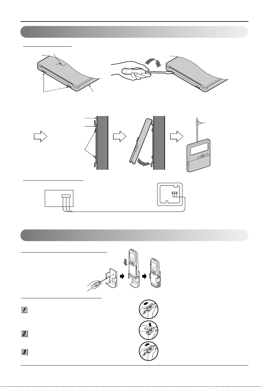
Wired Remote Control Installation
Remote Control Preparation
Remote control
box body
Cord clamp
(accessory)
Lever carefully
the box open
using a screw
driver, etc.
Front case
The lower part
Face of wall
Under plate
Screw (accessory)
Remote Controller Installation
HO
W TO MOUNT ONTO A WALL
HO
W TO INSERT BATTERIES
Remove the battery cover from the remote
controller.
• Slide the cover according to the arrow
direction.
Insert the two batteries.
• Be sure that the (+) and (-) directions are
correct.
• Be sure that both batteries are new.
Re-attach the cover.
• Slide it back into position.
• Fix the under plate on the wall
• Separate the under plate from Remote control box.
• Fix the cord clamps on the wall by
ø 3 tapping screws (accessory).
• Fix the remote control cord.
DISASSEMBLING
ELECTRICAL WIRING
Wire and make sure that terminal
numbers are matched on unit side and
remote controller side.
The maximum length of the cord is 100m.
If the length of the cord exceeds 50m,
use a wire size greater than 0.5mm
2
.
Remote controller
(Main board)
CN REMO
• Do not use rechargeable batteries,
such batteries differ from standard
dry cells in shape, dimensions, and
performance.
• Romove the batteries from the
remote controller if the air
conditioner is not going to be used
for some long time.
Installation Manual 11
ENGLISH
Wiring Connection
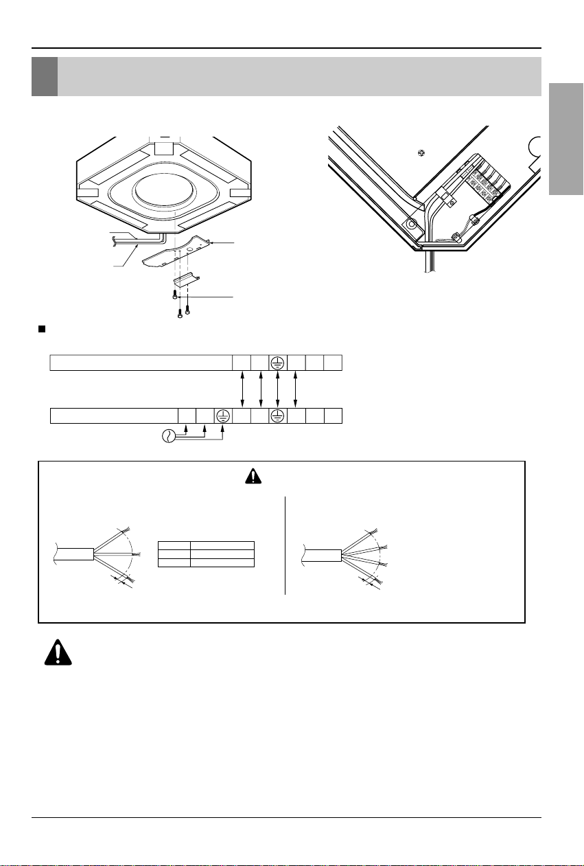
• Open the control box cover and connect the Remote controller cord and Indoor power wires.
[Air inlet side view]
Control box cover
Indoor
power cord
Remote
controller
cord
Control box cover screw
• Cooling & Heating type
The power cord connected to the outdoor unit should be
complied with the following specifications (Rubber
insulation, type H05RN-F approved by HAR or SAA).
If the supply cord is damaged, it must be replaced by a special cord or assembly available from the manufacturer of its service agent.
The connecting cable connected to the indoor and outdoor
unit should be complied with the following specifications
(Rubber insulation, type H05RN-F approved by HAR or SAA).
CAUTION
20mm
G
N
/Y
L
NORMAL
CROSS-SECTIONAL
AREA 2.1mm
2
(24k/34k)
20mm
G
N
/Y
L
Capacity
24k Btu/h
34k Btu/h
1 Phase
2.1mm
2
3.3mm
2
NORMAL CROSS-SECTIONAL AREA
24k/34k Btu/h (1Ø)
POWER
INPUT
Terminals on the indoor unit
Terminals on the outdoor unit
1(L) 2(N) 2(N) 31(L)
2(N) 3 4 51(L)
45
WARNING:
Make sure that the screws of the terminal are free from looseness.
Wiring Connection
12 Cassette type Air Conditioner
Electrical Wiring
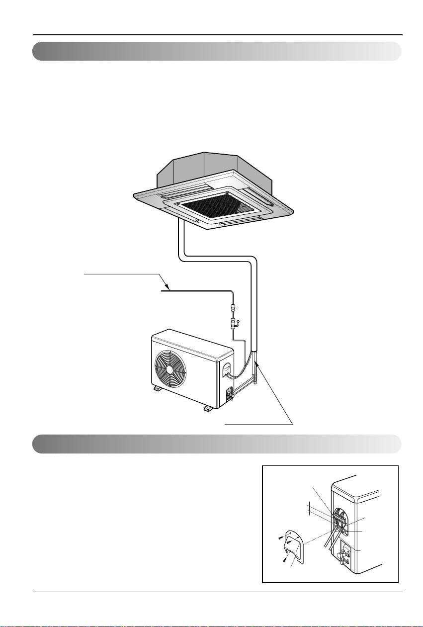
Connecting the cable to Outdoor Unit
Wiring Connection
1. All wiring must comply with LOCAL REGULATIONS.
2. Select a power source that is capable of supplying the current required by the air conditioner.
3. Feed the power source to the unit via a distribution switch board designed for this purpose.
4.The ter minal screws inside the control box may be loose due to vibration during transport.
Check the screws for loose connection.
(Running the air conditioner with loose connection can overload and damage electrical
components.)
5. Always ground the air conditioner with a grounding wire and connector to meet the LOCAL
REGULATION.
Main power source
Switch box
Refrigerant pipe
Circuit Breaker
Use circuit breaker or time delay fuse.
1. Remove the Cover control from the unit by loosening a
screw.
Connect the wires to the terminals on the control
board individually as following.
2. Secure the cable onto the control board with the
holder (clamper).
3. Refix the cover control to the original position with the
screw.
4. Use a recongnized circuit breaker between the power
source and the unit. A disconnection device to
adequately disconnect all supply lines must be fitted.
Outdoor unit
Terminal block
Over 5mm
(0.2")
Cover control
Conduit panel
Connecting
cable
Power supply
cord
Installation Manual 13
ENGLISH
Connecting Pipes to the Indoor Unit
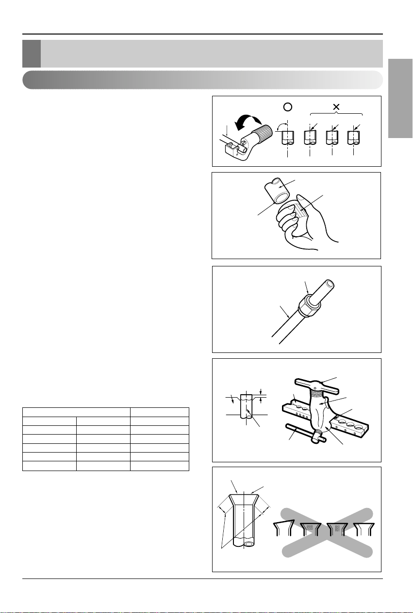
Main cause of gas leakage is defect in flaring
work. Carry out correct flaring work in the
following procedure.
1. Cut the pipes and the cable.
• Use the accessory piping kit or the pipes
purchased locally.
• Measure the distance between the indoor
and the outdoor unit.
• Cut the pipes a little longer than measured
distance.
•
Cut the cable 1.5m longer than the pipe
length.
2. Burrs removal
• Completely remove all burrs from the cut
cross section of pipe/tube.
•
Put the end of the copper tube/pipe to
downward direction as you remove burrs in
order to avoid to let burrs drop in the tubing.
3. Putting nut on
• Remove flare nuts attached to indoor and
outdoor units, than put them on pipe/tube
having completed burr removal.
(Not possible to put them on after flaring work)
4. Flaring work
•
Carry out flaring work using dedicated
flaring tool for R-410A as shown below.
Firmly hold copper tube in a bar(or die) as
indicated dimension in the table above.
5. Check
• Compare the flared work with figure below.
• If flare is noted to be defective, cut off the
flared section and do flaring work again.
Copper
tube
90°
Slanted Uneven Rough
Pipe
Reamer
Point down
Flare nut
Copper tube
Bar
Copper pipe
Clamp handle
Red arrow mark
Cone
Yoke
Handle
Bar
"A"
Inclined
Inside is shining without scratches
Smooth all round
Even length
all round
Surface
damaged
Cracked Uneven
thickness
= Improper flaring =
Connecting Pipes to the Indoor Unit
Preparation of Piping
Outside diameter A
mm inch mm
Ø6.35 1/4 1.0~1.5
Ø9.52 3/8 1.0~1.5
Ø12.7 1/2 1.0~1.5
Ø15.88 5/8 1.0~1.5
Ø19.05 3/4 2.0~3.0
14 Cassette type Air Conditioner
Connecting Pipes to the Indoor Unit
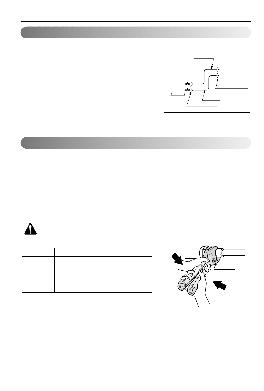
1. Form the piping according to its routing. Avoid
bending and bending back the same piping point
more than three times. (This will result in
hardening the pipe.)
2. After deforming the piping, align centers of the
union fitting of the indoor unit and the piping,
and tighten them firmly with wrenches.
3. Connect pipe to the service valve or ball valve
which is located below the outdoor unit.
4. After completing the piping connection, be sure
to check if there is gas leakage in indoor and
outdoor connection.
After completing the piping connection, execute
vacuum drying for the connecting piping and the
indoor unit.
The vacuum drying must be carried out using
the service ports of both the liquid and gas side
valves.
CAUTION:
Use two wrenches and
tighten with regular torque.
Outdoor
unit
Liquid side
Flare connection
Flare connection
Gas side
Indoor
unit
Union
Flare nut fastening torque
Ø6.35mm 1.8kg.m
Ø9.52mm 2.7kg.m
Ø12.7mm 3.7kg.m
Ø15.88mm 4.7kg.m
Ø19.05mm 5.7kg.m
Piping Connection
Vacuum drying
Installation Manual 15
ENGLISH
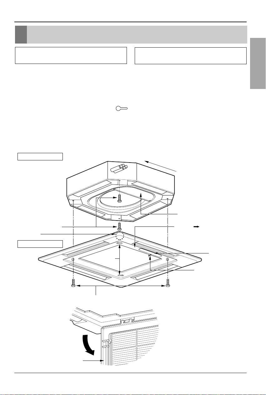
Installation to Decorative Panel
1.Temporarily fix two decorative panel fixing screws (hexagon M5 screw) on the unit body.
(Tighten by amount 10mm in length.)
The fixing screws (hexagon M5 screw) are included the decorative panel box.
2. Remove the air inlet grille from the decorative panel.(Remove the hook for the air inlet grille
cord.)
3. Hook the decorative panel key hole ( ) on the screws fixed in step above, and slide the
panel so that the screws reach the key hole edge.
4. Retighten completely two temporarily fixed screws and other two screws. (Total 4 screws)
5. Connect the louver motor connector and display connector.
6. After tightening these screws, install the air inlet grille (including the air filter).
Decorative panel fixing screws
(hexagon M5 screws)
Temporally fitting at 2 places
(Tightening about 10mm)
Install the panel after
making sure that the
piping side of the unit body
matches the piping
indication of the decorative
panel
Control box cover
Piping side
Inlet GrilleInlet GrilleInlet Grille
Inlet GrilleInlet Grille
Louver motor
Decorative panel fixing screws
(Hexagon M5 screw)
The arrow ( ) should point
to the side where the pipes are.
Air conditioner unit
Decorative panel
Key holes
Display
Lead wire for
louver motor and
display
The decorative panel has its installation
direction.
Before installing the decorative panel,
always remove the paper template.
Installation to Decorative Panel
16 Cassette type Air Conditioner
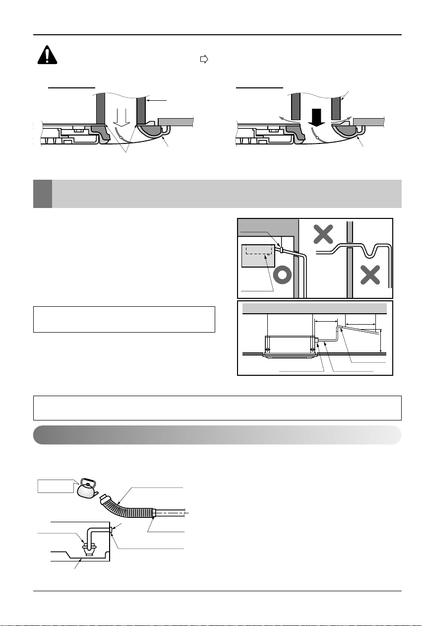
Indoor Unit Drain Piping
CAUTION:
Install certainly the decorative panel.
Cool air leakage causes sweating.
Water drops fall.
• Drain piping must have down-slope (1/50 to
1/100): be sure not to provide up-and-down
slope to prevent reversal flow.
• During drain piping connection, be careful
not to exert extra force on the drain port on
the indoor unit.
• The outside diameter of the drain
connection on the indoor unit is 32mm.
• Be sure to execute heat insulation on the
drain piping.
• Install the drain raising pipes at a right
angle to the indoor unit and no more than
300mm from the unit.
The air conditioner uses a drain pump to drain water.
Use the following procedure to test the drain pump operation:
• Connect the main drain pipe to the exterior and leave
it provisionally until the test comes to an end.
• Feed water to the flexible drain hose and check the
piping for leakage.
• Be sure to check the drain pump for normal
operating and noise when electrical wiring is
complete.
• When the test is complete, connect the flexible drain
hose to the drain port on the indoor unit.
Air conditioner
unit
Ceiling
board
Decorative panel
Decorative
panel
Fit the insulator (this part) and
be careful for cool air leakage
Good example
Air
Cool air leakage
(no good)
Bad example
Ceiling
board
Air conditioner unit
Maintenance
drain port
Upward
routing
not allowed
Pipe clamp
Indoor unit
700 or less
1 -1.5m
300mm or less
Clamp metal(attached) Drain hose(attached)
Drain raising pipe
Feed water
Drain Pump
Drain pan
Flexible drain hose
(accessory)
Main
drain pipe
Glue the joint
Drain
port
Drain hose connection
Use the clip (accessory)
Piping material: Polyvinyl chloride pipe VP-25
and pipe fittings
Heat insulation material: Polyethylene foam with thickness more than 8 mm.
Drain test
Indoor Unit Drain Piping
Installation Manual 17
ENGLISH
Indoor Unit Drain Piping
HEAT INSULATION
1. Use the heat insulation material for the refrigerant piping which has an excellent heatresistance (over 120°C).
2. Precautions in high humidity
circumstance:
This air conditioner has been tested
according to the "KS Standard
Conditions with Mist" and confirmed
that there is not any default.However, if
it is operated for a long time in high
humid atmosphere (dew point
temperature: more than 23°C), water
drops are liable to fall.In this case, add
heat insulation material according to the
following procedure:
• Heat insulation material to be
prepared... Adiabatic glass wool with
thickness 10 to 20mm.
• Stick glass wool on all air conditioners
that are located in ceiling atmosphere.
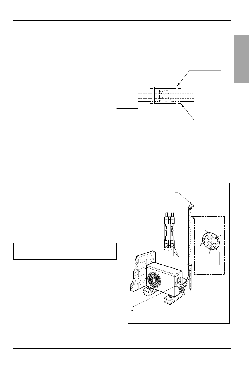
FORM THE PIPINGS
1.Wrap the connecting portion of indoor
unit with the Insulation material and
secure it with two Plastic Bands. (for the
right pipings)
• If you want to connect an additional drain hose,
the end of the drain-outlet should keep distance
from the ground. (Do not dip it into water, and fix
it on the wall to avoid swinging in the wind.)
2.Tape the Pipings, drain hose and
Connecting Cable from bottom to top.
3. Form the pipings gathered by taping
along the exterior wall and fix it onto the
wall by saddle or equivalent.
• In addition to the normal heat insulation
(thickness: more than 8mm) for refrigerant
piping (gas piping: thick piping) and drain
piping, add further 10mm to 30mm thickness
material.
Indoor unit
Thermal insulator
(accessory)
Fastening band
(accessory)
Refrigerant piping
In case of the Outdoor unit being installed
below position of the Indoor unit.
Seal a small opening
around the pipings
with gum type sealer.
Taping
Drain hose
Pipings
Plastic Band
Trap is required to prevent water from entering
into electrical parts.
Connecting
cable
Power supply
cord
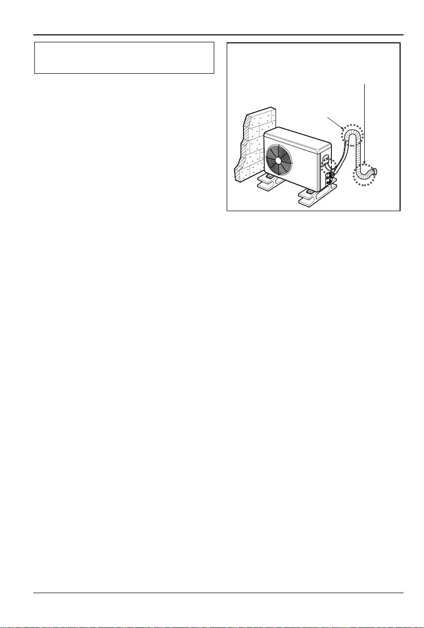
18 Cassette type Air Conditioner
Indoor Unit Drain Piping
2.Tape the Pipings and Connecting cable
from bottom to top.
3. Form the pipings gathered by taping along
the exterior wall, and make the trap prevent
water from entering into the room.
4. Fix the pipings onto the wall by saddle or
equivalent.
In case of the Outdoor Unit being installed
above position of the Indoor Unit.
Seal a small opening
around the pipings
with gum type sealer.
Trap
Test running
Installation Manual 19
ENGLISH
1. PRECAUTIONS IN TEST RUN
• The initial power supply must provide at least 90% of the rated voltage.
Otherwise, the air conditioner should not be operated.
CAUTION For test run, carry out the cooling operation firstly even during heating
season. If heating operation is carried out firstly, it leads to the trouble
of compressor.Then attention must be paid.
Carry out the test run more than 5 minutes without fail.
(Test run will be cancelled 18 minutes later automatically)
• The test run is started by pressing the room temperature checking button and down timer
button for 3 seconds at the same time.
• To cancel the test run, press any button.
CHECK THE FOLLOWING ITEMS WHEN INSTALLATION IS COMPLETE
• After completing work, be sure to measure and record trial run properties, and store measured
data, etc.
• Measuring items are room temperature, outside temperature, suction temperature, blow out
temperature, wind velocity, wind volume, voltage, current, presence of abnormal vibration and
noise, operating pressure, piping temperature, compressive pressure.
• As to the structure and appearance, check following items.
2. Connection of power supply
1. Connect the power supply cord to the independent power supply.
• Circuit breaker is required.
2. Operate the unit for fifteen minutes or more.
3. Evaluation of the performance
1. Measure the temperature of the
intake and discharge air.
2. Ensure the difference between the
intake temperature and the discharge
one is more than 8°C (Cooling) or
reversely (Heating).
Is the circulation of air adequate?
Is the draining smooth?
Is the heat insulation complete
(refrigerant and drain piping)?
Is there any leakage of refrigerant?
Is the remote controller switch operated?
Is there any faulty wiring?
Are not terminal screws loosened?
M4......118N.cm{12kgf.cm} M5......196N.cm{20kgf.cm}
M6......245N.cm{25kgf.cm} M8......588N.cm{60kgf.cm}
Test running
Thermometer
20 Cassette type Air Conditioner
CAUTION: After the confirmation of the above conditions, prepare the wiring
as follows:
1) Never fail to have an individual power specialized for the air conditioner. As
for the method of wiring, be guided by the circuit diagram pasted on the
inside of control box cover.
2) Provide a circuit breaker switch between power source and the unit.
3) The screw which fasten the wiring in the casing of electrical fittings are
liable to come loose from vibrations to which the unit is subjected during
the course of transportation. Check them and make sure that they are all
tightly fastened. (If they are loose, it could give rise to burn-out of the
wires.)
4) Specification of power source
5) Confirm that electrical capacity is sufficient.
6) Be sure that the starting voltage is maintained at more than 90 percent of
the rated voltage marked on the name plate.
7) Confirm that the cable thickness is as specified in the power sources
specification.
(Particularly note the relation between cable length and thickness.)
8) Never fail to equip a leakage breaker where it is wet or moist.
9) The following troubles would be caused by voltage drop-down.
• Vibration of a magnetic switch, damage on the contact point there of, fuse
breaking, disturbance to the normal function of a overload protection device.
• Proper starting power is not given to the compressor.
HAND OVER
Teach the customer the operation and maintenance procedures, using the operation manual
(air filter cleaning, temperature control, etc.).
Test r unning
Installation Manual 21
ENGLISH
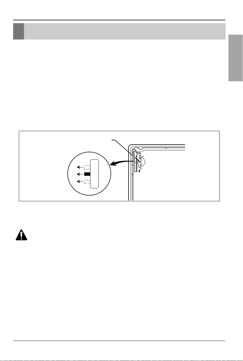
1.Two Thermistor System
(1) Open the rear cover of the wired remote-controller to set the mode.
(2) Select one of three selectable modes as follows.
• Position 1:The room themperature is controlled by the thermistor of the wired remotecontroller, control the temperature according to the position of wired remotecontroller.
• Position 2:The room temperature is controlled by the thermistor of the main body.
• Position 3:The room temperature is controlled by lower temperature between the
temperature of main body and of remote-controller sensor.
(3) Move the slide switch to set position.
(4) Close the rear cover and check if it works normally.
CAUTIO
N
:
• Select the position after counselling with a customer.
• In case of cooling mode, room temperature is controlled by the main body sensor.
• To control the room temperature by a wired remote controller, install controller(room
temp. sensor) to sense the temperature more accurately.
• Manufactured in the position 3.
Optional Operation
Optional Operation
Slide switch for 2 Thermistor
1
2
3
1
2
3
1
2
3
22 Cassette type Air Conditioner
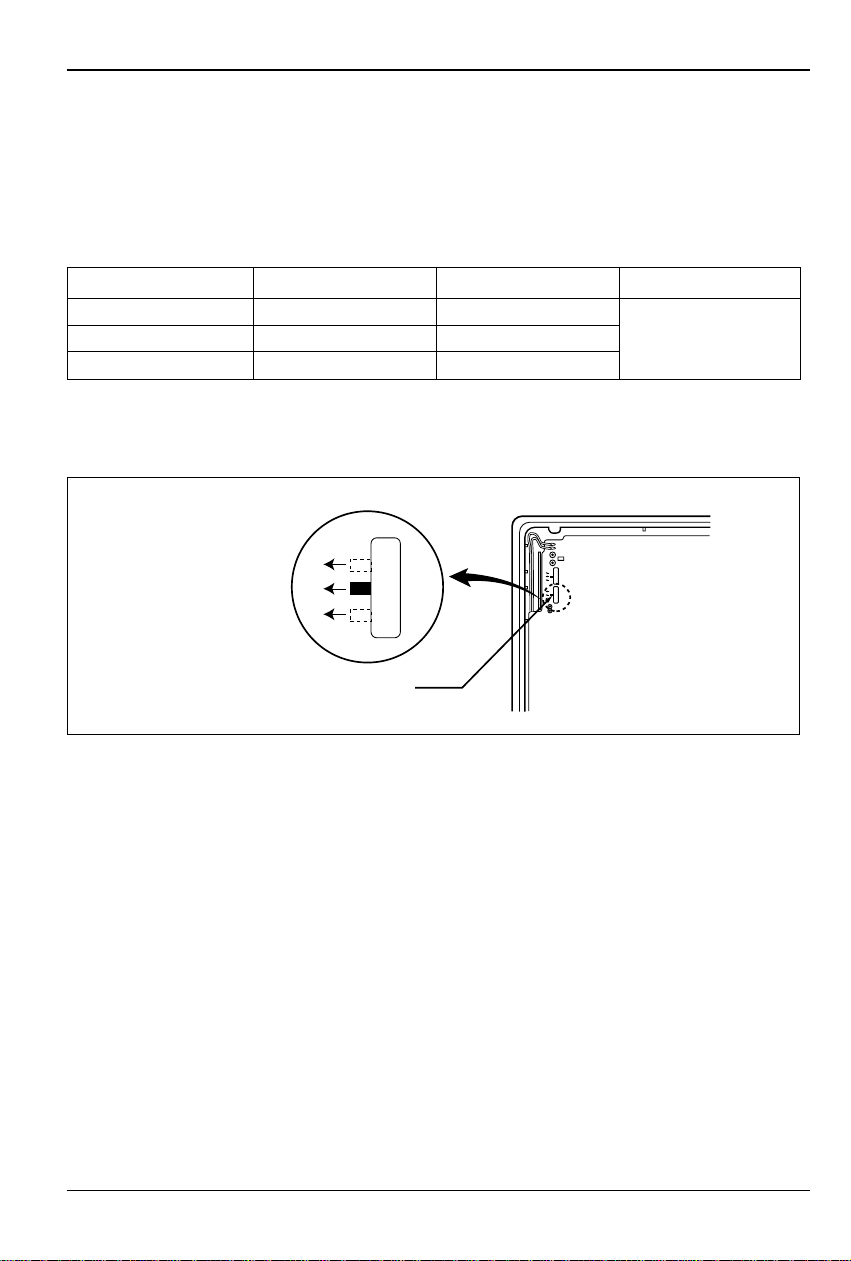
2. Adjusting air volume to the height of ceiling
You can choose the RPM(or air volume) of indoor motor according to the height of ceiling to
supply the comfortable atmosphere to consumers.
Procedure
1. Choose the selectable position in the table after measuring the height of ceiling.
2. In the case of changing the height as "high" or "low", open the rear cover of the wired remotecontroller.
3. Move the slide switch to the set position.
4. Close the rear cover and check if it works normally.
Optional Operation
Ceiling height Mode of slide switch Change of air volume Remark
more than 3.3m High Ceiling Increasing
2.7~3.3m Standard -
Manufactured in
less than 2.7m Low Ceiling Decreasing
standard mode
1
2
3
Slide switch for ceiling height
1
2
3
1
2
3

Installation Manual 23
ENGLISH
Optional Operation
3. Group Control(Optional Wiring)
• You can use a group control operation after connecting the brown and yellow wire of
each air-conditioner.
• Remove the resistor "OP 7" in remote controller.
• It operates maximum 16 Units by only one Wired Remote Controller,
and each Unit starts sequentially to prevent overcurrent.
Wiring design
Features
• Use Only One Wired Remote Controller with several air conditioners(max. 16 Units)
• Random starting to prevent overcurrent.
CAUTIO
N
:
• Be careful not to exchange the color of wires.
• The maximum length of connecting wire should be below 200m(25Ω) on connecting
each units.
• Use a wire more than 0.5mm
2
Operation unit
ZONE
1234
Humidify
JET
AUTO
AUTO SWING OPERATION
FAN SPEED
Program set
SUB FUNCTION
SET TEMP
Room Temp
HI
MED
LO
Heater
Defrost
Filter
Preheat
Out door
Time
Timer
On
Set no. Time
Off
01 03 05 07 09 11 13 15 17 19 21 23
Wired Remote Controller
Slide Switch
OP7
Remote
Controller
PCB
Main PCB
Indoor Unit 1
Terminal(Local Supply)
Block
Terminal(Local Supply)
Block
Terminal(Local Supply)
Block
Main PCB
#1
Main PCB
#2
Main PCB
#16
Indoor Unit 2
Main PCB
Indoor Unit 16
Connector
RED(12V)
YL(SIGNAL)
BR(GND)
RED(12V)
YL(SIGNAL)
BR(GND)
YL(SIGNAL)
BR(GND)
Connecting Cable(Local Supply)
Connector Connector
....
....
YL(SIGNAL)
BR(GND)
YL(SIGNAL)
BR(GND)
YL(SIGNAL)
BR(GND)

24 Cassette type Air Conditioner
Memo

FRANÇAIS
LG
Climatiseur Type Cassette
MANUALE D’INSTALLAZIONE
IMPORTANTE
• Veuillez lire au complet ce manuel d’instructions avant
installer le produit.
• Conformément aux standards nationaux sur le câblage,
l’installation ne doit être effectuée que par du personnel
autorisé.
• Après l’avoir lu au complet, veuillez conserver ce
manuel d’installation pour référence ultérieure.

2 Climatiseur Type Cassette
Climatiseur Type Cassette Manuel d'installation
TABLE DES MATIÈRES
Mesures de sécurité
......................................3
Installation des unités
interne et externe............6
Dimensions de l'ouverture
dans le plafond et
emplacement des boulons
de fixation........................8
Installation de I'unité
interne..............................9
Installation de la
télécommande.................9
Connexion des câbles..11
Connexion des conduits à
l'unité interne.................13
Installation du panneau
décoratif.........................15
Conduits de drainage
unité interne ..................16
Test de fonctionnement....
........................................19
Fonctionnement optionnel
........................................21
• Plaque de montage
• Quatre vis de type “A”
• Câble de raccordement
• Conduites : gaz Iiquide
• Tube d'évacuation isolés
• Matériaux isolants
•
Tube d'évacuation complémentaire
(Diam. extérieur5,5mm
)
• Deux vis de type "B"
• Niveau à bulle
• Tournevis
• Perecuse électrique
• Embout scie trépan (ø70mm)
• Jeux d'outils pour évasement
• Clés dynamométriques
• Clés dynamométriques
• Tournevis
• Clé six pans (4mm)
• Détecteur de fuite de gaz
• Guide de l'utilisateur
• Thermomètre
Travaux d'installation Eléments à installer Outillage

Mesures de sécurité
Manuel d'installation
3
FRANÇAIS
Les instructions ci-après doivent être observées dans le but de prévenir tout risque de
dommages corporels ou matériels.
■
L'utilisation non conforme, résultant de la négligence des instructions, est susceptible de
provoquer des dommages corporels ou matériels dont la gravité est signalée par les
indications suivantes :
■ Les significations des symboles utilisés dans ce manuel sont indiquées ci-dessous.
Ce symbole indique un risque de blessure grave, voire mortelle.
Ce symbole indique un risque de blessure ou des dommages
matériels seulement.
ATTENTION
Veillez à ne pas faire cela.
Veillez à suivre les instructions de ce manuel.
Mesures de sécurité
■ Installation
N'utilisez pas un coupe-circuit
défectueux ou à valeur nominale
inférieure. Utilisez cet appareil sur
un circuit dédié.
• Ceci risquerait de provoquer
un incendie ou un choc
électrique.
Pour un travail électrique, contactez
le distributeur, le vendeur, un
électricien qualifié ou un Centre de
Service Après Vente Agrée.
• Ne démontez ni réparez le
produit. Ceci risquerait de
provoquer un incendie ou un
choc électrique.
Faites toujours une connexion
reliée à la terre.
• Autrement vous risquerez de
provoquer un incendie ou un
choc électrique.
Installez fermement le panneau
et le couvercle du tableau de
commande.
• Autrement vous risquerez de
provoquer un incendie ou un
choc électrique.
Installez toujours un circuit et
un disjoncteur dédiés.
• Un câblage ou une installation
inappropriés peuvent
provoquer un incendie ou un
choc électrique.
Utilisez un disjoncteur ou
fusible à valeur nominale
appropriée.
• Autrement vous risquerez de
provoquer un incendie ou un
choc électrique.
ATTENTION
PRECAUTION

4 Climatiseur Type Cassette
Mesures de sécurité
Ne modifiez ni prolongez le cordon
d'alimentation.
• Ceci risquerait de provoquer un incendie ou
un choc électrique.
Prenez soin lorsque vous déballez et installez
ce produit.
•
Les bords aiguisés peuvent provoquer des
blessures.Faites attention en particulier aux
bords du boîtier et aux ailettes du condenseur et
de l'évaporateur.
Contactez toujours le revendeur ou un centre
de service après vente agréé pour effectuer
l'installation.
• Autrement, Vous
pourriez provoquer
un incendie, un
choc électrique,
une explosion ou
vous blesser.
N'installez pas le produit sur un support
d'installation défectueux.
• Ceci peut provoquer des blessures, un
accident ou bien endommager le produit.
Vérifiez que la zone d'installation n'est pas
abîmée par le temps.
•
Si la base s'écroule, le
climatiseur pourrait
tomber avec elle,
provoquant des
dommages matériels,
une défaillance du
produit et des blessures.
Ne laissez pas le climatiseur marcher trop
longtemps lorsque l'humidité est très élevée et
qu'il y a une porte ou une fenêtre ouverte.
• De l'humidité peut se condenser et mouiller
ou endommager le mobilier.
N'emmagasinez ni utilisez de substances
inflammables ou combustibles près de ce
produit.
• Ceci entraînerait un risque d'incendie ou de
défaillance du produit.
■ Fonctionnement
Gasolin

FRANÇAIS
Manuel d'installation
5
Mesures de sécurité
Vérifiez toujours s'il y a des fuites de gaz
(frigorigène) suite à l'installation ou réparation
du produit.
• Des niveaux de frigorigène trop bas peuvent
provoquer une défaillance du produit.
Installez le raccord de drainage de manière à
assurer un drainage approprié.
• Une mauvaise connexion peut provoquer
des fuites d'eau.
Maintenez le produit au niveau lors de son.
• Installation afin d'éviter des vibrations ou des
fuites d'eau.
N'installez pas le produit à un endroit où le
bruit ou l'air chaud dégagés de l'unité
extérieure dérangent les voisins.
• Ceci pourrait entraîner des problèmes avec
vos voisins.
Faites appel à deux ou plusieurs personnes
pour enlever et transporter ce produit.
• Evitez des blessures.
N'installez pas ce produit à un endroit où il
serait exposé directement au vent de la mer
(pulvérisation d'eau de mer).
• Ceci peut provoquer de la corrosion sur le
produit. La corrosion, particulièrement sur les
ailettes du condenseur et de l'évaporateur,
peut provoquer un dysfonctionnement ou un
fonctionnement inefficace du produit.
PRECAUTION
90°
■ Installation

6 Climatiseur Type Cassette
Installation des unités interne et externe
Installation des unités interne et externe
Sélection du meilleur emplacement
1. Unité interne
• Il ne doit pas y avoir d'autres sources de
chaleur ou de vapeur à côté de l'unité.
• Il ne doit y avoir aucun obstacle qui puisse
bloquer la circulation de l'air.
• Un emplacement où la circulation de l'air
dans la pièce est bonne.
• Un emplacement où le drainage peut être
facilement réalisé.
• Un emplacement où une protection contre
le bruit est prise en considération.
• N'installez pas l'unité à côté d'une porte.
• Assurez-vous des espaces indiqués par
les flèches depuis le mur, le plafond ou
d'autres obstacles.
• L'unité interne doit avoir un espace pour
l'entretien.
2. Unité externe
• Si un store est placé au-dessus de l'unité
pour la protéger contre les rayons solaires
ou la pluie, faites attention que les
radiations de chaleur provenant du
condensateur ne soient pas bloquées.
• Aucun animal ou plante ne doit être affecté
par l'air chaud déchargé.
• Assurez-vous des espaces indiqués par
les flèches depuis le mur, le plafond ou
d'autres obstacles.
unité : cm.
Plafond
panneau
du plafond
panneau du plafond
30 ou plus
250-300 ou
moins
100 ou
plus environ
50 ou
plus
50 ou
plus
30 ou moins
plancher
Sunroof
plus de 30 cm
clôture ou
obstacles
plus de
50cm
clôture ou
obstacles
Sunroof
plus de
More than
30cm
30 cm
plus de 50 cm
plus de 70 cm
More than
plus de
30cm
50cm
plus de 50cm
plus de 100cm

Manuel d'installation
7
FRANÇAIS
Installation des unités interne et externe
3. Longueur et élévation des conduites
A
B
A
B
A
B
Unité intérieure
Unité intérieure
Unité intérieure
Unité extérieure
Unité extérieure
Unité extérieure
Piège à huile
Si la tuyauterie mesure plus de 5 m
PRECAUTION:
• Performance nominale pour longueur ligne réfrigérant
de 7,5 m
• La capacité est basée sur la longueur standard et la longueur maximale permise
est en fonction de la fiabilité.
• Une charge frigorifique inappropriée peut provoquer un cycle anormal.
• Un piège à huile doit être installé tous les 10 mètres.
24k Btu/h
1/2"(12.7mm) 1/4"(6.35mm)
7.5(25') 30(100') 5(16') 15(50') 20(0.22 oz./ft.)
34k Btu/h
5/8"(15.88mm) 1/4"(6.35mm)
7.5(25') 35(115') 5(16') 20(66') 30(0.32 oz./ft.)
CAPACITÉ
Réfrigérant
supplémentaire
(g/m)
Dimensions du tuyau
(Diamètre: Ø)
Longueur A (m) Elevazione B (m)
Gaz Liquide Standard Maximum Standard Maximum

8 Climatiseur Type Cassette
• Sélectionnez et marquez la position des boulons de
fixation et de l'ouverture pour les conduits.
• Décidez la position des boulons de fixation
légèrement inclinés dans la direction du drainage
après avoir considéré la direction du tuyau de
drainage.
• Percez le trou pour le boulon d'ancrage dans le
mur.
PRECAUTION:
•
Ce climatiseur utilise une pompe de drainage.
• Installez horizontalement l'unité en utilisant
une jauge de niveau.
• Pendant l'installation faites attention de ne
pas endommager les câbles électriques.
• Étudiez attentivement les emplacements d'installation suivants :
1.Dans certains lieux comme des restaurants et des cuisines, une grand quantité de vapeur d'huile et de
farine adhère au ventilateur, aux ailettes de l'échangeur de chaleur et à la pompe de drainage, ce qui
provoque une réduction de l'échange de chaleur, une vaporisation, une dispersion d'eau, un mauvais
fonctionnement de la pompe de drainage, etc.
Dans ces situations, effectuez les interventions suivantes :
• Faites attention que le ventilateur de ventilation de la hotte sur le dessus de cuisson ait une capacité
suffisante pour aspirer les vapeurs d'huile qui n'entrent ainsi pas dans l'aspiration du climatiseur.
• Laissez suffisamment de distance depuis le dessus de cuisson pour installer le climatiseur là où il
n'aspirera pas la vapeur d'huile.
2. Évitez d'installer le climatiseur dans des usines où se trouvent des suspensions d'acier en poudre ou
d'huiles, etc...
3. Évitez les lieux où des gaz inflammables se trouvent, pénètrent ou sont conservés.
4. Évitez les lieux où sont produits des gaz d'acide sulfurique ou des gaz corrosifs.
5. Évitez les lieux proches de générateurs de haute fréquence.
REMARQUE
Dimensions de l'ouverture dans le plafond et emplacement des boulons de fixation
• Les dimensions du modèle sur papier pour l'installation sont les mêmes que celles de l'ouverture dans le plafond.
Unité : cm
840 taille unité
840 taille unité
101.5101.5
875 (ouverture dans le plafond)
875 (ouverture dans le plafond)
785 (boulons de fixations)
45
45
672 (boulons de
fixations)
Panneau du plafond
Jauge de
niveau
Plafond
dessus de cuisson
Climatiseur
distance
suffisante
Utilisez le ventilateur de la
hotte avec une capacité
suffisante.
Dimensions de l'ouverture dans le plafond et emplacement des boulons de fixation

Manuel d'installation
9
FRANÇAIS
• Vous pouvez choisir les pièces suivantes.
Boulon de fixation W 3/8 ou M10
Écrou - W 3/8 ou M10
Rondelle M10
Rondelle plate M10
AVVISO:
Serrez les écrous et les
boulons pour éviter que l'unité ne
tombe.
• Percez l'ouverture pour les conduits dans le mur
légèrement inclinée vers l'extérieur en utilisant une
mèche de perceuse de 70.
Mur
5~7mm
Interne
Externe
Réglez les vis sur le
modèle en papier
(4 pièces)
modèle en papier
pour installation
panneau plafond
150mm
Réglez
à la même hauteur
panneau
du plafond
Plafond
Rondelle plate pour M10
(accessoire)
Conservez la longueur du boulon
depuis le support à 40 mm
Ouvrez le panneau du
plafond le long du bord
externe du modèle en papier
Rondelle plate pour M10
(accessoire)
boulon de fixation
(W3/8 ou M10)
Écrou
(W3/8 ou M10)
Écrou
(W3/8 ou M10)
Rondelle
(M10)
corps climatiseur
Installation de l'unité interne
• Puisque le capteur de température de la pièce est dans l'unité interne, la télécommande
doit être installée au même endroit, éloignée des rayons solaires et de l'humidité élevée.
Installation de la télécommande
• Sélectionnez un emplacement qui ne soit pas éclaboussé par de l'eau.
• Sélectionnez la position de contrôle après avoir obtenu l'approbation du client.
• Le capteur de température de la pièce est à l'intérieur de l'unité interne.
• Cette télécommande est équipé d'un affichage à cristaux liquides. Si la position est trop élevée
ou trop basse, on lit mal l'affichage. (Le standard est une hauteur de 1,2 1,5 m)
Acheminement du câble de la télécommande
• Placez le câble de la télécommande éloigné des conduits du réfrigérant et de drainage.
• Pour protéger le câble de la télécommande des parasites électriques, placez-le à au moins 5 cm
des autres câbles d0alimentation (équipement audio, téléviseur, etc.).
• Si le câble de la télécommande est fixé au mur, mettez un collecteur au-dessus du câble pour
éviter que de l'eau ne lui tombe dessus.
Installation de I'unité interne
Installation de la télécommande

10 Climatiseur Type Cassette
Installation de la Télécommande avec fils
Preparation de la Télécommande
• Fixez le plateau inférieur au mur.
• Séparez le plateau inférieur du boîtier de la télécommande.
• Fixez les pinces du câble au mur avec des vis filetées Ø
3 (accessoires).
• Fixez le câble de la télécommande.
corps boîtier
télécommande
Pince du câble
(accessoire)
Soulevez délicatement
le boîtier en utilisant
un tournevis, etc.
boîtier avant
partie inf
érieur
Mur
Plateau inférieur
Vis (accessoires)
Installation de la télécommande
COMMENT LA MONTER AU MUR
COMMENT INTR
ODUIRE LES PILES
Enlevez le couvercle de la télécommande
Faites glisser le couvercle dans la direction
de la flèche.
Introduisez 2 piles.
• Faites attention que les directions (+) et (-)
soient correctes
• Faites attention que les deux piles soient
neuves.
Remettez en place le couvercle
Faites-le glisser en position
DÉMONT
AGE
CÂBLAGE ÉLECTRIQUE
Télécommande
Panneau principal
CN REMO
Faites l'installation électrique et contrôlez que
les numéros des bornes correspondent sur
l'unité interne et sur la télécommande.
La longueur maximale du câble est de 100 m.
Si la longueur du câble dépasse les 50 m,
utilisez un câble de taille supérieure à 0,5 mm .
2
• N'utilisez pas de piles
rechargeables, ces piles sont
différentes des piles sèches
standard comme forme, dimensions
et performances.
• Enlevez les piles de la
télécommande si le climatiseur
n'est pas utilisé pendant longtemps.

Manuel d'installation
11
FRANÇAIS
Connexion des câbles
• Ouvrez le couvercle du boîtier de contrôle et connectez le câble de la télécommande et les
câbles d'alimentation internes.
[Vue côté admission d'air]
Couvercle boîtier
de contrôle
Cordon
d'alimentation
interne
Cordon
télécommande
Vis de montage du couvercle
du boîtier de contrôle
Le cordon d'alimentation connecté à l'unité externe doit être
conforme aux spécifications suivantes (isolation en
caoutchouc, type H05RN-F approuvé par HAR ou SAA).
Le cordon d'alimentation connecté à l'unité externe et à
l'unité externe doit être conforme aux spécifications
suivantes (isolation en caoutchouc, type H05RN-F
approuvé par HAR ou SAA).
PRECAUTION
Alimentation
en entr
SURFACE SECTION
TRANSVERSALE NORMALE
• Si le câble d’alimentation est endommagé, il doit être remplacé par un câble spécial ou d’assemblage fourni par le fabricant ou le service
d’assistance.
•
Type réfrigérant et chauffant
20mm
G
N/YL
SURFACE SECTION
TRANSVERSALE
NORMALE
2.1mm2 (24k/34k)
Capacity
24k Btu/h
34k Btu/h
1 Phase
2.1mm
2
3.3mm
2
24k/34k Btu/h (1Ø)
Terminal sur le groupe interne
Terminal sur le groupe externe
1(L) 2(N) 2(N) 31(L)
2(N) 3 4 51(L)
45
20mm
G
N/YL
ATTENTION:
Contrôlez que les vis des bornes ne soient pas serrées.
Connexion des câbles

12 Climatiseur Type Cassette
Cäblages électriques
Connexion du Cäble a l'unité externe
Connexion des câbles
1.Tous les câblages doivent être conformes aux RÈGLES LOCALES.
2. Sélectionnez une source d'alimentation capable de fournir le courant nécessaire au climatiseur.
3. Fournissez le courant à l'appareil à travers un tableau de distribution conçu dans ce but.
4. Les vis des bornes à l'intérieur du boîtier de contrôle pourraient être desserrées à cause de
vibrations pendant le transport. Contrôlez ces vis des connexions desserrées.
(Faire fonctionner le climatiseur avec des connexions desserrées peut surcharger et
endommager les composants électriques).
5. Effectuez toujours la mise à terre du climatiseur avec un câble de terre et un connecteur qui
satisfont aux RÈGLES LOCALES.
Source principale d'alimentation
boîtier des interrupteurs
tuyau réfrigérant
Coupe-circuit
Utilisez le coupe-circuit ou un fusible de retard
1. Enlevez le couvercle de contrôle de l'unité en
dévissant la vis. Branchez les câbles aux bornes
sur le panneau de contrôle de la manière
suivante.
2. Assurez le câble au panneau de contrôle avec
des supports (pinces).
3. Remettez en place le couvercle de contrôle avec
la vis.
4. Utilisez un coupe-circuit reconnu entre la source
d'alimentation et l'unité. Un appareil de
débranchement. pour débrancher toutes les
lignes de fourniture doit être monté.
Unité extérieure
Boîte à bornes
Au-dessus
de 5mm
(2")
Couvercle du panneau
de commandes
Panneau de
commandes
Câble de
connexion
Câble
d’alimentation
électrique

Manuel d'installation
13
FRANÇAIS
Connexion des conduits á l'unité interne
Préparation des conduits
La cause principale des fuites de gaz est un
défaut dans le travail d'évasement. Effectuez
correctement le travail d'évasement en
suivant la procédure ci-dessous.
1. Coupez les conduits et le câble
• Utilisez le kit de tuyaux ou des tuyaux
achetés par vous.
• Mesurez la distance entre l'unité interne et
l'unité externe.
• Coupez les tuyaux un peu plus longs que
la distance mesurée.
• Coupez le câble 1,5 m plus long que la
longueur des tuyaux.
2. Enlevez les bavures
• Éliminez complètement les bavures de la
section transversale coupée des tuyaux.
• Placez l'extrémité des tuyaux en cuivre
vers le bas pour que vous puissiez éliminer
les bavures afin d'éviter d'en laisser à
l'intérieur des tuyaux.
3. Montez l'écrou
• Enlevez les écrous évasés montés sur les
unités interne et externe, puis placez-les
sur les tuyaux après avoir éliminé les
bavures.(Il n'est plus possible de les
monter après avoir effectuer le travail
d'évasement)
4.Travail d'évasement
• Exécutez le travail d’évasement en utilisant
l’outil évasé pour R-410A comme suit.
Tenez fermement le tuyau en cuivre dans
une barre (ou une matrice) de dimensions
indiquées dans le tableau ci-dessus.
5. Contrôle
• Comparez le travail d'évasement avec la
figure.
•
Si vous avez noté que l'évasement est
défectueux, coupez la section évasée et
effectuez de nouveau le travail d'évasement.
Tuyau en
cuivre
90°
biseauté non uniforme rugueux
Tuyau
Alésoir
Pointez vers
le bas
écrou évasé
Tuyau en cuivre
Barre
tuyau en cuivre
Poignée pince
Flèche rouge
Cône
Étau
Poignée
Barre
"A"
incliné
intérieur est brillant sans rayures
lisse tout autour
longueur uniforme
tout autour
surface
endommagée
fissuréépaisseur
non uniforme
= Mauvais évasement =
Connexion des conduits à l'unité interne
Diamètre externe A
mm inch mm
Ø6.35 1/4 1.0~1.5
Ø9.52 3/8 1.0~1.5
Ø12.7 1/2 1.0~1.5
Ø15.88 5/8 1.0~1.5
Ø19.05 3/4 2.0~3.0

14 Climatiseur Type Cassette
Connexion des conduits
Séchage avec aspirateur
Connexion des conduits á l'unité interne
1. Façonnez les conduits selon leur cheminement.
Évitez de cambrer et de recambrer le même
point du conduit plus de trois fois (Cela
provoquerait un durcissement du tuyau).
2. Après avoir façonné les conduits, alignez les
centres d'union de l'unité interne et des conduits,
et serrez-les fermement avec une clé.
3. Connectez le tuyau à la soupape de connexion
ou à la soupape à boule qui est placée sous
l'unité externe.
4. Après avoir achevé la connexion des conduits,
contrôlez s'il y a des fuites de gaz dans les
connexions interne et externe.
Completati i collegamenti dei tubi, eseguire
lasciugatura con vuoto per i tubi di connessione
e unità interna.
Lasciugatura sotto vuoto deve essere eseguita
utilizzando le aperture di servizio apposite delle
valvole sia del lato liquido che del lato gas.
PRECAUTION:
Utilisez deux clés et
serrez avec un couple de serrage régulier.
unité
externe
côté liquide
connexion évasée
connexion évasée
côté gaz
unité
interne
Union
Couple de serrage écrou évasé
Ø6,35mm 1,8kg.m
Ø9,52mm 2,7kg.m
Ø12,7mm 3,7kg.m
Ø15,88mm 4,7kg.m
Ø19,05mm 5,7kg.m

Manuel d'installation
15
FRANÇAIS
Installation du panneau décoratif
1. ixez temporairement deux vis de fixation du panneau décoratif (vis hexagonales M5) sur le
corps de l'unité. (Serrez sur une longueur d'environ 10 mm). Les vis de fixation (vis
hexagonales M5) sont fournies avec le panneau de décoration.
2. Enlevez la grille interne du panneau décoratif.(Enlevez le crochet pour le câble de la grille
interne).
3. Accrochez les ouvertures en forme de clé ( ) du panneau décoratif sur les vis fixées
au point ci-dessus et faites glisser le panneau jusqu'à ce que les vis atteignent le bord de
l'ouverture en forme de clé.
4. Serrez complètement les deux vis temporaires fixées et les deux autres vis (total 4 vis).
5. Connectez le connecteur du moteur des volets et le connecteur d'affichage.
6. Après avoir serré ces vis, installez la grille interne (comprenant le filtre à air).
Vis de fixation (vis hexagonales M5)
du panneau décoratif
Fixation temporaire en 2 points
(serrage sur environ 10 mm)
Couvercle boîtier de contrôle
Côté conduits
Inlet GrilleInlet Grillegrille interne
Inlet GrilleInlet Grille
Moteur volets
Vis de fixations Panneau décoratif
(vis hexagonales M5)
La flèche ( ➡ ) pointe vers le
côté où se trouvent les tuyaux.
Unité climatiseur
Panneau décoratif
Ouvertures
à clé
Affichage
Câble double pour
moteur volets et
affichage
Installer le panneau après
avoir vérifié que le côté
tuyaux de l'unité
corresponde bien avec les
indications tuyaux du
panneau décoratif.
Le panneau décoratif a sa direction
d'installation.
Avant d'installer le panneau décoratif,
enlevez toujours le patron en papier.
Installation du panneau décoratif

16 Climatiseur Type Cassette
Le climatiseur utilise une pompe de drainage pour drainer l'eau.
Suivez les procédures suivantes pour tester le fonctionnement de la pompe de drainage.
• Connectez le tuyau principal de drainage à
l'extérieur et laissez-le provisoirement jusqu'à
ce que le test ne s'achève.
• Remplissez d'eau le tuyau flexible de drainage
et contrôlez s'il y a des fuites.
• Contrôlez que la pompe de drainage
fonctionne normalement quand le câblage
électriques est complet.
• Quand le test est terminé, connectez le tuyau
flexible de drainage à l'ouverture de drainage
de l'unité externe.
Conduits de drainage unité interne
• Les conduits de drainage doivent être en
pente vers le bas (1/50 à 1/100) : contrôlez
de ne pas donner une pente vers le haut et
vers le bas pour éviter le flux inverse.
• Pendant la connexion des conduits de
drainage, faites attention de ne pas exercer
trop de force sur les ouvertures de drainage
de l'unité interne.
• Le diamètre externe de la connexion de
drainage de l'unité interne est de 32 mm.
• Contrôlez de bien avoir effectué l'isolation
des conduits de drainage.
PRECAUTION:
Installez le panneau décoratif.
Des fuites d'air froid provoquent des suintements
è Des gouttes d'eau tombent.
Unité climatiseur
Panneau
du plafond
Panneau décoratif
Panneau
décoratif
Montez l'isolant (cette pièce) et
faites attention aux fuites d'air froid.
Bon exemple
Air
Fuites d'air froid
(mauvais)
Mauvais exemple
Panneau
du plafond
Unité climatiseur
Ouverture
d'entretien de
drainage
Pince de tuyau
unité interne
acheminement
vers le haut n'est
pas permis
700 or less
1 -1.5m
300mm or less
Clamp metal(attached) Drain hose(attached)
Drain raising pipe
Remplissez
d'eau
Pompe de drainage
Filtre de drainage
Tuyau flexible de drainage
(accessoire)
tuyau principal
de drainage
Collez la jonction
ouverture
de drainage
connexion tuyau de drainage
utilisez une pince (accessoire)
Matériel des conduits : tuyaux en chlorure
de polyvinyle Vp-25 et accessoires des
tuyaux.
Matériel d'isolation de chaleur : Mousse de polyéthylène avec une épaisseur de plus de 8 mm.
Conduits de drainage unité interne
Test de Drainage

Manuel d'installation
17
FRANÇAIS
Conduits de drainage unité interne
ISOLATION A LA CHALEUR
1. Utilisez le matériel d'isolation à la chaleur pour les tuyaux du liquide réfrigérant qui ont une
résistance à la chaleur excellente (plus de 120°C).
2. Précautions dans le cas d'humidité
élevée :Ce climatiseur a été testé dans
les "conditions standard KS avec
vapeur" et il est confirmé qu'il n'a pas
de défauts.Toutefois, s'il fonctionne
pendant longtemps dans une
atmosphère très humide (température
du point de condensation : plus de
23°C), un écoulement d'eau peut se
vérifier.Dans ce cas, ajoutez du
matériel d'isolation en suivant la
procédure suivante :
• Matériel d'isolation à la chaleur à préparer...Laine de verre adiabatique avec une épaisseur de
10 à 20 mm.
• Collez de la laine de verre sur tous les climatiseurs qui sont placés au plafond.
• En plus de la normale isolation à la chaleur (épaisseur : plus de 8 mm) pour le tuyau du
réfrigérant (tuyau de gaz : tuyau épais) et le tuyau de drainage, ajoutez de 10 à 30 mm
d'épaisseur de matériel.
FAÇONNAGE DES TUYAUX
1. Enveloppez la portion de connexion de
l'unité interne avec du matériel d'isolation
et assurez-le avec deux bandes en
plastique (pour les tuyaux de droite).
• Si vous voulez connecter un tuyau
supplémentaire de drainage, l'extrémité de
la sortie de drainage doit être à une
certaine de distance du sol. (Ne le plongez
pas dans l'eau et fixez-le au mur pour éviter
les oscillations provoquées par le vent).
2. Enveloppez les tuyaux,le tuyau de
drainage et le câble de connexion du bas
au sommet.
3. Façonnez les tuyaux en les enveloppant
sur le mur extérieur et en les fixant au
mur par une selle ou quelque chose
d'équivalent.
unité interne
isolant thermique
(accessoire)
bande de serrage
(accessoire)
tuyau du réfrigérant
Dans le cas d'une unité externe en cours
d'installation, abaissez la position de
l'unité interne.
Scellez une petite
ouverture autour
des tuyaux avec de
gomme pour sceller
tuyau de drainage
enveloppe
tuyaux
bande en
plastique
Il faut un séparateur pour éviter que l’eau
pénètre dans les composants électriques.
câble de
connexion
d'alimentation
cordon

18 Climatiseur Type Cassette
Conduits de drainage unité interne
2. Enveloppez les tuyaux et le câble de
connexion du bas au sommet.
3. Façonnez les tuyaux en les enveloppant
sur le mur extérieur et réalisez un
collecteur pour éviter que de l'eau n'entre
dans la pièce.
4. Fixez les tuyaux au mur par une selle ou
quelque chose d'équivalent.
Dans le cas d'une unité externe en cours
d'installation, soulevez la position de l'unité
interne.
Seal a small opening
around the pipings
with gum type sealer.
Trap

Test de fonctionnement
Manuel d'installation
19
FRANÇAIS
1. PRÉCAUTIONS PENDANT LE TEST DE FONCTIONNEMENT
• L'alimentation initiale devrait fournir au moins 90% de la tension nominale.
Autrement, le climatiseur ne peut pas fonctionner.
PRECAUTION:
Á Pour le test de fonctionnement,effectuez d'abord les opérations de refroidissement
même en hiver. Si vous effectuez d'abord les opérations de chauffage, cela pourrait
conduire à des problèmes du compresseur. Donc, faites attention.
Ë Effectuez le test de fonctionnement pendant 5 minutes sans interruption.
(Le test sera effacé 18 minutes plus tard automatiquement).
• Le test de fonctionnement commence en appuyant sur la touche de contrôle de la température de
la pièce et sur la touche minuterie pendant 3 secondes en même temps.
• Pour annuler le test de fonctionnement, appuyez sur n'importe quelle touche.
CONTRÔLEZ LES ÉLÉMENTS SUIVANTS QUAND L'INSTALLATION EST COMPLÈTE
• Après avoir achevé le travail, mesurez et enregistrez les propriétés du test de fonctionnement et
conservez les données mesurées, etc.
• Les éléments à mesurer sont la température de la pièce, la température externe, la température
d'aspiration, la température d'expulsion, la vitesse du vent, la tension, le courant, la présence de
vibrations anormales ou de bruits, la pression de fonctionnement, la température des tuyaux, la
pression de compression.
• Pour la structure et l'apparence, contrôlez les éléments suivants :
La circulation de l'air est-elle suffisante ?
Le drainage se fait-il sans problèmes ?
L'isolation à la chaleur est-elle complète
(tuyaux de réfrigérant et de drainage ) ?
Y a-t-il des fuites de réfrigérant ?
L'interrupteur de la télécommande
fonctionne-t-il ?
Y a-t-il de mauvais câblages ?
Des vis de bornes sont-elles desserrées ?
M4......118N.cm{12kgf.cm} M5......196N.cm{20kgf .cm}
M6......245N.cm{25kgf.cm} M8......588N.cm{60kgf .cm}
Test de fonctionnement
2) Connexion de l'alimentation
1. Branchez le cordon d'alimentation à
une prise de courant indépendante.
• Un coupe-circuit est nécessaire.
2. Faites fonctionner l'appareil
pendant quinze minutes ou plus.
3) Évaluation des performances
1. Mesurez la température de l'air en
admission et en sortie
2. Assurez-vous que la différence entre
la température de l'air en admission
et celle de l'air en sortie est
supérieure à 8°C (refroidissement) ou
inversement.(Chauffage)
Thermomètre

20 Climatiseur Type Cassette
PRECAUTION: Après la confirmation des conditions ci-dessus, préparez les
câblages de la manière suivante :
1) Il faut absolument que le climatiseur ait une prise de courant
spécialisée. Pour la méthode de câblage, faites-vous guider par les
diagrammes de circuit à l'intérieur du couvercle du boîtier de contrôle.
2) Mettez un coupe-circuit entre la source d'alimentation et l'appareil.
3) Les vis qui serrent le câblage dans la chemise des installations
électriques peuvent se desserrer à cause de vibrations auxquelles
l'appareil est soumis pendant le transport. Contrôlez-les et faites
attention qu'elles soient toutes bien serrées. (Si elles sont desserrées,
cela pourrait provoquer un court-circuit des câbles).
4) Spécifications de la source d'alimentation.
5) Confirmation que la capacité électrique est suffisante.
6) Contrôlez que la tension de mise en marche soit bien maintenue à au
moins 90% de la tension nominale indiquée sur la plaque.
7) Confirmation que l'épaisseur du câble est bien celle spécifiée dans les
spécifications de la source d'alimentation. (Remarquez en particulier la
relation entre la longueur du câble et son épaisseur).
8) Il faut toujours monter un coupe-fuites dans des endroits humides ou
mouillées.
9) Les problèmes suivants pourraient être provoqués par une chute de
tension.
• Vibrations de l'interrupteur magnétique, dommage au point de contact,
rupture de fusible, problèmes de fonctionnement du système de protection
contre les surcharges.
• Une puissance de mise en marche suffisante n'est pas fournie au
compresseur.
TRANSMISSION DES INFORMATIONS
Enseignez à l'utilisateur les procédures de fonctionnement et d'entretien en utilisant le manuel de
fonctionnement (nettoyage du filtre à air, contrôle de la température, etc.)
Test de fonctionnement

Manuel d'installation
21
FRANÇAIS
1. Système à deux thermistors
(1) Ouvrez le couvercle arrière de la télécommande pour régler le mode.
(2) Sélectionnez un des trois modes sélectionnables de la manière suivante :
• Position 1 :La température de la pièce est contrôlée par le thermistor de la télécommande,
il contrôle la température selon la position de la télécommande.
• Position 2 :La température de la pièce est contrôlée par le thermistor du corps principal.
• Position 3 :La température de la pièce est contrôlée par la température inférieur entre la
température du corps principal et du capteur de la télécommande.
(3) Déplacez l'interrupteur coulissant sur la position réglée.
(4) Fermez le couvercle arrière et contrôlez si l'appareil fonctionne normalement.
PRECAUTION:
• Sélectionnez la position après vous être conseillé avec l'utilisateur.
• Dans le cas du mode refroidissement, la température de la pièce est contrôlée par le
capteur du corps principal.
• Pour contrôler la température de la pièce par la télécommande, installez la
télécommande (capteur température de la pièce) pour capter plus précisément la
température.
• Fabriqué en position 3.
Fonctionnement optionnel
Fonctionnement optionnel
Interrupteur coulissant pour 2 thermistors
1
2
3
1
2
3
1
2
3

22 Climatiseur Type Cassette
2. Réglage du volume d'air à la hauteur du plafond
Vous pouvez choisir les tours/minute (ou le volume d'air) du moteur interne selon la hauteur du
plafond pour fournir une atmosphère confortable aux utilisateurs.
Procédure
1. Choisissez la position sélectionnante dans le tableau après avoir mesuré la hauteur du
plafond.
2. En cas de changement de hauteur en "haut" ou "bas", ouvrez le couvercle arrière de la
télécommande.
3. Déplacez l'interrupteur coulissant sur la position réglée
4. Fermez le couvercle arrière et contrôlez si l'appareil fonctionne correctement.
Fonctionnement optionnel
Interrupteur coulissant pour plafond haut
1
2
3
1
2
3
1
2
3
Hauteur du plafond Mode interrupteur coulissant Changement volume d'air Remarque
3,3 m Plafond haut Augmentation
2,7~3,3 m Standard -
2,7 m Plafond bas Diminution
Construit en mode
standard

Manuel d'installation
23
FRANÇAIS
Fonctionnement optionnel
Fonctions
• Utilisation d'une seule télécommande avec fils avec plusieurs climatiseurs.
(max. 16 appareils)
• Démarrage en séquence pour éviter des surcharges de courant.
PRECAUTION:
• Faites attention de pas échanger les couleurs des câbles.
• La longueur maximale du câble de connexion doit être inférieure à 200 m (25) pour
connecter chaque appareil.
• Utilisez un câble de plus de 0,5 mm2.
3. Contrôle groupe (câblages optionnels)
• Vous pouvez utiliser le fonctionnement de contrôle de groupe après avoir connecté les
câbles marron et jaune de chaque climatiseur.
• Enlevez la résistance "OP7" de la télécommande.
• Ce système fait fonctionner au maximum 16 appareils avec une seule télécommande
avec fils et chaque appareil se met en marche en séquence pour éviter une surcharge
de courant.
Dessin câblag
es
Operation unit
ZONE
1234
Humidify
JET
AUTO
AUTO SWING OPERATION
FAN SPEED
Program set
SUB FUNCTION
SET TEMP
Room Temp
HI
MED
LO
Heater
Defrost
Filter
Preheat
Out door
Time
Timer
On
Set no. Time
Off
01 03 05 07 09 11 13 15 1719 2123
Télécommande avec fils
interrupteur coulissant
OP7
PCB
télécommande
Unité interne 1
Bloc bornes (Fourniture locale)
PCB principal
#1
PCB principal
#2
PCB principal
#16
Unité interne 2
PCB principal
Unité interne 16
Connecteur
Bloc bornes (Fourniture locale)
Connecteur
Bloc bornes (Fourniture locale)
Connecteur
RED(12V)
YL(SIGNAL)
BR(GND)
YL(SIGNAL)
BR(GND)
YL(SIGNAL)
BR(GND)
Câble de connexion (fourniture locale)
....
....
YL(SIGNAL)
BR(GND)
YL(SIGNAL)
BR(GND)
YL(SIGNAL)
BR(GND)

24 Climatiseur Type Cassette
Note

ESPAÑOLESPAÑOL
LG
Aire acondicionado de Tipo Cassete
MANUAL DE INSTALACIÓN
IMPORTANTE
• Lea este manual de instrucciones completamente antes de
instalar el producto.
• El trabajo de instalación debe realizarse de acuerdo con el
Reglamento Eléctrico nacional y únicamente por personal
autorizado.
• Después de leer completamente este manual de instalación,
guárdelo para futuras consultas.

2 Aire acondicionado de Tipo Cassete
Aire acondicionado de Tipo Cassete Manual de instalación
ÍNDICE
Precauciones de
seguridad
......................................3
Instalación de las unidades
Interior y Exterior ...............6
Dimensiones del hueco del
techo y ubicación del
perno de suspensión.........8
Instalación de la unidad
Interior..................................9
Conexión del cableado....11
Conexión de las tuberías a
la unidad Interio................13
Instalación del Panel
Decorativo.........................15
Tubería de drenaje du la
unidad interior ..................16
Prueba de Funcionamiento
.............................................19
Funcionamiento Opcional.
.........................................21
•
Cable de conexión
• Tuberías:Lado del gas
Lado del líquid
• Perno de suspensión
(W 3/8) o M10, longitud 650 mm)
• Manguera de drenaje con
aislamiento
• Manguera adicional de drenaje
(Diámetro interior: 32 mm
•
Nivel
• Destornillador
• T aladro eléctrico
• Broca (ø70 mm)
• Juego de herramientas de
abocardado
• Llaves torsiométricas
• Llave hexagonal (4 mm, 5 mm)
• Detector de fugas de gas
• Manual de propietario
• T ermómetro
Trabajos de instalación Componentes de instalación Herramientas necesarias

Precauciones de seguridad
Manual de instalación
3
ESPAÑOL
Para evitar lesiones al usuario o a otras personas y daños a la propiedad, siga estas
instrucciones.
■
Una operaci’on incorrecta por ignorar las instrucciones provocará lesiones o daños.La
seriedad se clasifica por las siguientes indicaciones.
■ Significados de los símbolos utilizados en este manual.
Este símbolo indica la posibilidad de muerte o de seria lesión.
Este símbolo indica sólo la posibilidad de lesión o daño a la propiedad.
ADVERTENCIA
Prohibido.
Recuerde seguir las instrucciones.
Precauciones de seguridad
■ Instalación
No utilice un interruptor automático
defectuoso o de valor nominal inferior
al correspondiente. Utilice un circuito
específico para este aparato.
• Existe riesgo de incendio o
descarga eléctrica.
Para trabajos eléctricos, póngase en
contacto con el distribuidor, vendedor,
técnico cualificado o centro de
asistencia técnica autorizado.
• No desmonte ni repare el
aparato.Existe r iesgo de
incendio o descarga eléctrica.
Realice siempre la conexión
del aparato a tierra.
• Existe riesgo de incendio o
descarga eléctrica.
Instale correctamente el
panel y la cubierta de la
caja de control.
• Existe riesgo de incendio o
descarga eléctrica.
Instale siempre un circuito y
un interruptor específico.
• Un cableado o instalación
inadecuados pueden provocar
un incendio o una descarga
eléctrica.
Utilice el interruptor o
fusible de valor nominal
adecuado.
• Existe riesgo de incendio o
descarga eléctrica.
ADVERTENCIA
PRECAUCIÓN

4 Aire acondicionado de Tipo Cassete
Precauciones de seguridad
No modifique ni extienda el cable de
alimentación.
• Existe riesgo de incendio o descarga
eléctrica.
Tenga cuidado al desembalar e instalar el
aparato.
•
Los bordes afilados podrían provocar lesiones.
Tenga especial cuidado con los bordes de la caja
y las aletas del condensador y evaporador.
Para la instalación, póngase en contacto
siempre con su vendedor o centro de
asistencia técnica autorizado.
• Existe riesgo de incendio, descarga
eléctrica, explosión o lesiones.
No instale el aparato en una superficie de
instalación insegura.
• Podría causar lesiones, accidentes o daños
en el aparato.
Asegúrese de que el soporte de instalación no
se deteriora con el tiempo.
•
Si el soporte cae, el aire acondicionado también puede
caer, causando daños materiales, avería del aparato y
lesiones personales.
No deje funcionando el aire acondicionado
durante mucho tiempo cuando la humedad sea
muy alta y haya una puerta o ventana abierta.
• Podría condensarse la humedad y mojar o
dañar el mobiliario.
No almacene ni utilice gas inflamable o
combustibles cerca del aparato.
• Existe riesgo de incendio o avería del
aparato.
■ Operación
Gasolin

Manual de instalación
5
ESPAÑOL
Precauciones de seguridad
Compruebe siempre las fugas de gas
(refrigerante) después de la instalación o
reparación del aparato.
• Niveles bajos de refrigerante pueden
producir una avería del aparato.
Instale la manguera de drenaje para asegurarse
de que el agua se drena correctamente.
• Una mala conexión puede causar fugas de
agua.
Instale el aparato bien nivelado.
• Para evitar las vibraciones o fugas de agua.
No instale el aparato donde el ruido o el aire
caliente de la unidad exterior pueda molestar a
los vecinos.
• Podría tener problemas con los vecinos.
Levante y transporte el aparato entre dos o más
personas.
• Evite lesiones personales.
No instale el aparato donde quede expuesto
directamente al viento del mar (rocío salino).
• Podría causar corrosión en el aparato. La
corrosión, particularmente en las aletas del
condensador y del evaporador, podría causar
un funcionamiento defectuoso del aparato o
un funcionamiento ineficaz.
PRECAUCIÓN
90°
■ Instalación

6 Aire acondicionado de Tipo Cassete
Instalación de las unidades Interior y Exterior
Instalación de las unidades Interior y Exterior
1. Unidad Interior
• Cerca de la unidad no debe existir
ninguna fuente de calor o de vapor.
• No debe existir ningún obstáculo que
impida la circulación del aire.
• Elija un lugar de la habitación donde haya
buena circulación de aire.
• Elija un lugar donde se facilite un buen
desagüe a la unidad.
• Elija un lugar teniendo en cuenta el ruido
que produce el aparato.
• No instale la unidad cerca de una puerta
de paso.
• Asegúrese de que existen los espacios
libres indicados por las flechas desde la
pared, el techo u otros obstáculos.
• La unidad interior debe disponer de un
espacio suficiente para su mantenimiento.
2. Unidad Exterior
• Si se coloca un protector sobre la unidad
para evitar la luz directa del sol o la lluvia,
asegúrese de que la radiación de calor del
condensador no quede restringida.
• No coloque animales o plantas donde
puedan quedar afectados por la salida del
aire caliente.
• Asegúrese de que queden los espacios
libres indicados por las flechas desde la
pared, el techo, barandillas u otros
obstáculos.
Elección de la mejor ubicación
Unidad: cm
Placa de
techo
Techo
Placa de techo
30
o más
más de
250/330
o menos
100
o más
50 o
más
50 o
más
30 o menos
Suelo
Más de
30cm
Protector
Barandilla u
obst
áculo
Más de
50cm
Barandilla u
obst
áculo
Más de 70cm
Protector
Más de 100cm
More than
Más de
30cm
30cm
Más de 50cm
More than
Más de
30cm
50cm
Más de 50cm

Manual de instalación
7
ESPAÑOL
Installazione dellunità Interna, Esterna
3. Longitud y altura de las tuberías
A
B
A
B
A
B
Unidad interna
Unidad interna
Unidad interna
Unidad externa
Unidad externa
Unidad externa
Separador de aceite
Si la longitud del conducto es superior a 5 m
PRECAUCIÓN:
• Rendimiento nominal para una longitud de la tubería de refrigerante de 7,5 m
• La capacidad está basada en la longitud estándar y la longitud máxima permitida
depende de la fiabilidad.
• Una carga indebida de refrigerante puede ocasionar un ciclo anormal.
• Debería instalarse un colector de aceite cada 10 metros.
24k Btu/h
1/2"(12.7mm) 1/4"(6.35mm)
7.5(25') 30(100') 5(16') 15(50') 20(0.22 oz./ft.)
34k Btu/h
5/8"(15.88mm) 1/4"(6.35mm)
7.5(25') 35(115') 5(16') 20(66') 30(0.32 oz./ft.)
Capacidad
Refrigerante
adicional
(g/m)
Medidas Tubos
(Diámetro: Ø)
Longitud A(m) Elevación B(m)
Gas Líquido Estándar Máxima Estándar Máxima

8 Aire acondicionado de Tipo Cassete
• Elija y marque la posición de los tornillos de
fijación y del orificio de la tubería.
• Decida la posición de los tornillos de fijación
ligeramente inclinados hacia la dirección de
desagüe después de considerar la dirección de
la manguera de drenaje.
• Taladre en la pared el orificio para el perno de
anclaje.
PRECAUCIÓN:
• Este acondicionador de aire utiliza
una bomba de
drenaje.
• Instale horizontalmente la unidad utilizando un
nivel.
• Durante la instalación, tenga cuidado de no dañar
los cables eléctricos.
• Estudie detenidamente las siguientes ubicaciones para la instalación:
1. En lugares como restaurantes y cocinas se suele adherir una cantidad considerable de vapor de aceite y polvo
al turboventilador, a la aleta del intercambiador térmico y a la bomba de drenaje, provocando una reducción en
el proceso de intercambio térmico, el rociado y dispersión de gotas de agua, un mal funcionamiento de la
bomba de drenaje, etc.
En estos casos, lleve a cabo las siguientes acciones:
• Asegúrese de que el extractor de la campana de humos de la cocina tiene suficiente capacidad para
absorber el vapor aceitoso, el cual no debe fluir hacia el elemento de succión del acondicionador de aire.
• Para instalar el acondicionador de aire, deje distancia suficiente hasta la cocina de forma que el aparato no
se impregne de vapor aceitoso.
2. Evite la instalación del acondicionador de aire en fábricas donde haya en suspensión neblina de aceites de
corte o polvo de hierro.
3. Evite lugares donde se generen, fluyan, se almacenen o se ventilen gases inflamables.
4. Evite lugares donde se generen gases ácidos o corrosivos.
5. Evite lugares cerca de generadores de alta frecuencia.
AVISO
Dimensiones del hueco del techo y ubicación del perno de suspensión
• Las dimensiones del modelo de papel para la instalación son iguales que las del hueco del techo.
Placa del techo
Nivel
Techo
Utilice une campana extractora de
humos con una capacidad suficiente.
Fogón
Acondicionador de aire
Deje una
distancia
suficiente
Unidad:mm
840 Medida de la unidad
840 Medida de
la unidad
672 (Perno
de suspensión)
101.5101.5
875 (Hueco del techo)
875 (Hueco del techo)
785(Perno de suspensión)
45
45
Dimensiones del hueco del techo y ubicación del perno de suspensión

Manual de instalación
9
ESPAÑOL
• Las piezas siguientes son opcionales:
Perno de suspensión W 3/8 o M10
Tuerca W 3/8 o M10
Arandela de resorte M10
Arandela plana M10
PRECAUCIÓN:
Apriete la tuerca y
el perno para evitar el
desprendimiento de la unidad.
• Taladre en la pared el orificio de la tubería ligeramente
inclinado hacia el exterior utilizando una broca ø70.
Pared
5~7mm
Interior Exterior
Tornillo de fijación
del modelo de papel
(4 unidades)
Modelo de papel para
la instalación
Placa del techo
150mm
Ajuste la misma altura
Placa de techo
Techo
Arandela plana para M10
(accesorio)
Arandela plana para M10
(accesorio)
Mantenga la longitud del perno
desde la abrazadera de 40 mm
Abra la placa del techo a
lo largo del borde exterior
del modelo de papel.
Perno de suspensión
(W3/8 o M10)
Tuerca (W3/8 o M10)
Techo
Tuerca
(W 3/8 o M10)
Arandela de resorte
(M10)
Cuerpo del
acondicionador
de aire
Instalación de la unidad Interior
• Aunque el sensor de temperatura de la habitación se encuentra en la unidad interior, el
mando a distancia se debe instalar en un lugar que no reciba la luz directa del sol y que
no tenga mucha humedad.
Instalación del mando a distancia
• Elija lugares donde no se produzcan salpicaduras de agua.
• Elija la posición del mando después de recibir la aprobación del cliente.
• El sensor de temperatura de la habitación se encuentra dentro de la unidad interior.
• Este mando a distancia está equipado con una pantalla de cristal líquido. Si su posición es
demasiado elevada o demasiado baja, resultará difícil la lectura de la pantalla (la altura estándar
es 1,2 a 1,5 m de altura).
Disposición del cable del mando a distancia
• Mantenga el cable del mando a distancia separado de la tubería del refrigerante y de la tubería
de drenaje.
• Para proteger el cable del mando a distancia de ruidos eléctricos, coloque el cable a 5 cm de
distancia como mínimo de cualquier cable de potencia (equipos de audio, televisores, etc.).
• Si el cable del mando a distancia se sujeta a la pared, coloque un separador en la parte
superior del cable para evitar que durante el funcionamiento se produzcan goteos de agua.
Instalación de la unidad Interior
Instalación del mando a Distancia

10 Aire acondicionado de Tipo Cassete
Instalación del mando a distancia con cable
Preparación del mando a distancia
Cuerpo de la caja
del mando a distancia.
Grapa del cable
(accesorio)
Levantar cuidadosamente
la caja para abrirla
utilizando un destornillador o similar.
Caja delantera
La parte inferior
Cara de la pared
Placa inferior
Tornillos (accesorio)
Instalación del mando a Distancia
CÓMO INSTALARLO EN UNA PARED
CÓMO COLOCAR LAS PILAS
Retire la tapa de las pilas del mando a
distancia.
• Deslice la tapa siguiendo la dirección de
la flecha.
Coloque las dos pilas
• Asegúrese de que las direcciones (+) y (-)
son correctas.
• Asegúrese de que las dos pilas son
nuevas.
Vuelva a colocar la tapa
• Deslícela de nuevo a su posición.
• Coloque la placa inferior en la pared.
•
Separe la placa inferior de la caja del mando a distancia.
• Coloque las grapas del cable en la pared utilizando
tornillos roscadores de ø3 (accesorios).
• Coloque el cable del mando a distancia.
DESMONT
AJE
CABLEADO ELÉCTRICO
Realice el empalme y asegúrese de que los
números de terminal coinciden en el lado de la
unidad y en el lado del mando a distancia.
La longitud máxima del cable es 100 m.
Si la longitud del cable supera los 50 m,
utilice un cable con una sección superior a 0,5 mm
2
.
Mando a distancia
(Tablero principal)
CN REMO
• No utilice pilas recargables; ese tipo
de pilas son distintas a las pilas
secas estándares en su forma,
dimensiones y rendimiento.
• Retire las pilas del mando a
distancia si el acondicionador de
aire no se va a utilizar durante un
periodo prolongado de tiempo.

Manual de instalación
11
ESPAÑOL
Conexión del cableado
• Abra la tapa de la caja de control y conecte el cable del mando a distancia y los cables de
alimentación de la unidad interior.
[Vista lateral de la
entrada de aire]
El cable de conexión conectado a las unidades interior y
exterior deben cumplir las siguientes especificaciones
(Aislamiento de caucho, tipo H05RN-F aprobado
por HAR o SAA)
El cable de alimentación conectado a la unidad exterior
debe cumplir las siguientes especificaciones
(Aislamiento de caucho, tipo H05RN-F aprobado
por HAR o SAA)
Tapa de la caja de control
Cable de alimentación
de la unidad interior
Cable del mando
a distancia
Tornillos de fijación
de la tapa de la caja de control
• Si el cable de alimentación está dañado, debe ser sustituido por un cable especial o por un conjunto que
se puede conseguir en el fabricante o en su servicio oficial.
PRECAUCIÓN
ÁREA NORMAL DE LA SECCIÓN TRANSVERSAL
• Modelo calor y frío
20mm
G
N/YL
ÁREA NORMAL DE LA
SECCIÓN TRANSVERSAL
2.1mm2 (24k/34k)
Capacity
24k Btu/h
34k Btu/h
1 Phase
2.1mm
2
3.3mm
2
24k/34k Btu/h (1Ø)
Entrada de corriente
Bloque de Terminales de la Unidad Interior
Bloque de terminales de la unidad Exterior
1(L) 2(N) 2(N) 31(L)
2(N) 3 4 51(L)
45
20mm
G
N/YL
ADVERTENCIA:
Asegúrese de que los tornillos del terminal no estén flojos.
Conexión del cableado

12 Aire acondicionado de Tipo Cassete
Cableado Eléctrico
Conexión del cable a la unidad exterior
Conexión del cableado
1.Todos los cables deben cumplir la NORMATIVA LOCAL.
2. Elija una fuente de alimentación que sea capaz de suministrar la corriente que necesita el
acondicionador de aire.
3. La alimentación eléctrica a la unidad debe realizarse por medio de un tablero de distribución
diseñado para este propósito.
4. Los tornillos de los terminales en el interior de la caja de control pueden aflojarse a causa de las
vibraciones durante el transporte del aparato.Compruebe si los tornillos se han aflojado.(El
funcionamiento del acondicionador de aire con las conexiones flojas puede provocar una
sobrecarga y dañar los componentes eléctricos).
5. Conecte siempre a tierra el acondicionador de aire con un cable de tierra y un conectador para
cumplir la NORMATIVA LOCAL.
Fuente principal de
alimentación
Caja de distribución
Tubería del refrigerante
Disyuntor
Utilice un disyuntor o un fusible de retardo
1. Retire la tapa del control de la unidad aflojando
un tornillo.
Conecte individualmente los cables a los
terminales del tablero de control según las
siguientes instrucciones.
2. Sujete el cable al tablero de control con el
soporte (fijador)
3.Vuelva a colocar la tapa de control en su posición
original con el tornillo.
4. Utilice un disyuntor aprobado de entre la fuente
de alimentación y la unidad. Se debe instalar un
dispositivo de desconexión para que se
desconecten de forma adecuada todas las líneas
de suministro.
Unidad exterior
Bloque de terminales
Sobre los
5 mm(2")
Cubierta de control
Panel de conductos
de distribución
Cable de
conexión
Cable de
alimentación

Manual de instalación
13
ESPAÑOL
Conexión de las tuberías a la unidad Interio
La principal causa de las fugas de gas es un
defecto en el proceso de conexión por
abocardado.Realice estas conexiones
observando el procedimiento siguiente.
1. Cor te las tuberías y el cable
• Utilice el juego de tuberías facilitado o
tuberías que adquiera usted mismo.
• Mida la distancia existente entre las
unidades interior y exterior.
• Corte las tuberías con una longitud
ligeramente superior a la distancia medida.
• Corte el cable 1,5 m más largo que la
longitud de la tubería.
2. Eliminación de irregularidades
• Elimine completamente todas las
irregularidades del tubo en el punto en que
haya sido cortado.
• Coloque el extremo del tubo de cobre
hacia abajo mientras elimina las
irregularidades para evitar que caigan
restos en el tubo.
3. Colocación de la tuerca
• Retire las tuercas abocardadas que se
encuentran en las unidades interior y
exterior y colóquelas en la tubería una vez
eliminadas todas las irregularidades.
(No es posible colocarlas después del
proceso de abocardado)
4. Abocardado
• Tenga cuidado en la labor de
acampanamiento utilizando herramientas
correspondientes para R-410A como se
muestra abajo.
Sujeta con firmeza el tubo de cobre en el
troquel siguiendo las dimensiones indicadas
en la tabla anterior.
5. Comprobación
• Compruebe el resultado del abocardado
con la figura de la derecha.
• Si observa que el abocardado es
defectuoso, corte la sección abocardada y
realice de nuevo la operación.
Tubo de
cobre
90°
Sesgado Desigual Áspero
Tubo
Escariador
Incline hacia abajo
Tuerca abocardada
Tubo de cobre
Troquel
Tubo de cobre
Manilla del tornillo
Marca de la flecha roja
Cono
Estribo de
montaje
Manivela
Troquel
"A"
Inclinado
El interior tiene brillo y no presenta rayas
Liso en toda la superficie
Longitud igual
Superficie
dañada
Con grietas Grosor
desigual
= Abocardado incorrecto =
Conexión de las tuberías a la unidad Interio
Preparación de las tuberías
Diámetro exterior A
mm inch mm
Ø6.35 1/4 1.0~1.5
Ø9.52 3/8 1.0~1.5
Ø12.7 1/2 1.0~1.5
Ø15.88 5/8 1.0~1.5
Ø19.05 3/4 2.0~3.0

14 Aire acondicionado de Tipo Cassete
Conexión de las tuberías
Secamiento al vacío
1. Dé forma a la tubería según el recorrido que
vaya a tener. Evite doblar y enderezar un
determinado punto de la tubería más de tres
veces (Provocará que se endurezca el tubo).
2. Después de darle forma a la tubería, realice la
alineación de los adaptadores de unión de la
unidad interior y la tubería y apriételos después
con firmeza con unas llaves inglesas.
3. Conecte la tubería a la válvula de servicio o
válvula esférica ubicada debajo de la unidad
exterior.
4.Tras finalizar la conexión de la tubería,
asegúrese de comprobar si hay fugas de gas en
las conexiones de las unidades interior y
exterior.
Tras finalizar la conexión de las tuberías, realice
un secamiento al vacío de la tubería de
conexión y la unidad interior.
El secamiento al vacío se debe realizar
utilizando los puertos de servicio de las válvulas
de los lados del líquido y del gas.
PRECAUCIÓN:
Utilice dos llaves inglesas
y apriete con un par de apriete regular.
Conexión de las tuberías a la unidad Interio
Unidad
Exterior
Lado del líquido
Conexión abocardada
Conexión
aborcardada
Lado del gas
Unidad
Interior
Unión
Par de apriete de la tuerca abocardada
Ø6,35mm 1,8kg.m
Ø9,52mm 2,7kg.m
Ø12,7mm 3,7kg.m
Ø15,88mm 4,7kg.m
Ø19,05mm 5,7kg.m

Manual de instalación
15
ESPAÑOL
Instalación del Panel Decorativo
1. Coloque provisionalmente dos tornillos de fijación del panel decorativo (tornillos hexagonales
M5) en el cuerpo de la unidad (Apriete unos 10 mm de longitud).
Los tornillos de fijación (hexagonales de M5) están incluidos en la caja del panel decorativo.
2. Retire la rejilla de entrada de aire del panel decorativo (retire el gancho para el cable de la
rejilla de entrada de aire).
3. Enganche el orificio de la llave del panel decorativo ( ) en los tornillos fijados en el
paso anterior y deslice el panel de forma que los tornillos alcancen el extremo del orificio de la
llave.
4.Vuelva a apretar completamente los dos tornillos de fijación provisionales y otros dos tor nillos
(en total 4 tornillos).
5. Conecte el conector del motor de la persiana y el conector del indicador.
6. Después de apretar estos tornillos, instale la rejilla de entrada de aire (incluyendo el filtro de
aire).
Tornillos de fijación del panel
decorativo (tornillos hexagonales M5)
Colocación provisional en 2
puntos (apretar alrededor
de 10 mm)
Instale el panel después de
asegurarse que el lado de la
tubería del cuerpo de la
unidad coincide con la indicación
de tubería del panel decorativo.
Tapa de la caja de control
Lado de la tubería
Inlet Grille
Rejilla de entrada
Inlet Grille
Louver motor
Tornillos de fijación del panel decorativo
(tornillos hexagonales M5)
Motor de la persiana
La flecha ( ) debe señalar
hacia el lado donde están los
tubos
Unidad del acondicionador de aire
Panel decorativo
Orificios para
las llaves
Indicador
Hilo conductor para
el motor de la persiana
y el indicador
El panel decorativo tiene su propia
dirección de instalación.
Antes de instalar el panel decorativo,
retire siempre las plantillas de papel.
Instalación del Panel Decorativo

16 Aire acondicionado de Tipo Cassete
El acondicionador de aire utiliza una bomba de drenaje para desaguar el agua.
Utilice el procedimiento siguiente para comprobar el funcionamiento de la bomba de drenaje:
• Conecte el tubo principal de drenaje al exterior
y déjelo provisionalmente hasta que finalice la
prueba.
• Vierta agua en la manguera flexible de drenaje
y compruebe si la tubería tiene fugas.
• Asegúrese de comprobar que la bomba de
drenaje funciona correctamente y la existencia
de posibles ruidos cuando se finalice el
cableado eléctrico.
• Cuando finalice la prueba, conecte la
manguera flexible de drenaje al puerto de
drenaje de la unidad interior.
Tubería de drenaje du la unidad interior
• La tubería de drenaje debe estar inclinada
hacia abajo (1/50 a 1/100): para evitar la
inversión del flujo, asegúrese de que no
existe una inclinación hacia arriba y hacia
abajo.
• Durante la conexión de la tubería de
drenaje, tenga cuidado de no ejercer
demasiada fuerza en el puerto de drenaje
de la unidad interior.
• El diámetro exterior de la conexión de
drenaje en la unidad interior es 32 mm.
• Asegúrese de realizar el aislamiento
térmico en la tubería de drenaje.
PRECAUCIÓN:
Instale correctamente el panel decorativo.
Las fugas de aire frío provocan condensació
è Caída de gotas de agua.
Unidad del acondicionador
de aire
Placas
del techo
Panel decorativo
Coloque el aislante (esta pieza) y
tenga cuidado con las fugas de aire frío.
Ejemplo de realización correcta
Aire
Fugas de aire frío
(no es bueno)
Ejemplo de realización incorrecta
Placas
del techo
Unidad del
acondicionador de aire
Panel decorativo
Mantenimiento del
puerto de prenaje
Recorrido
ascendente
no permitido
Abrazadera
del tubo
Unidad interior
700 or less
1 -1.5m
300mm or less
Clamp metal(attached) Drain hose(attached)
Drain raising pipe
Agua
Bomba de drenaje
Bandeja de drenaje
Manguera flexible de drenaje
(accesorio)
Tubo principal
de drenaje
Pegue la unió
Puerto de
drenaje
Conexión de la manguera
de drenaje
Utilice el clip (accesorio)
Manguera flexible de drenaje
Material de la tubería: Tubo de cloruro de
polivinilo VP-25 y adaptadores del tubo.
Material del aislamiento térmico: espuma de polietileno con un espesor superior a 8 mm.
Prueba de Drenaje
Tubería de drenaje du la unidad interior

Manual de instalación
17
ESPAÑOL
Tubería de drenaje du la unidad interior
AISLAMIENTO TÉRMICO
1. Utilice el material de aislamiento térmico para la tubería del refrigerante ya que tiene una
excelente resistencia térmica (más de 120°C).
2. Precauciones en condiciones de gran
humedad:
Este acondicionador de aire ha sido ensayado
de acuerdo con las Condiciones Estándares
KS con Humedad y se ha confirmado que no
tiene ningún defecto.Sin embargo, si se pone
en funcionamiento durante un periodo
prolongado de tiempo en una atmósfera con
gran humedad (temperatura del punto de
condensación superior a 23°C), es posible
que caigan gotas de agua. En este caso,
añada material de aislamiento térmico según
el procedimiento siguiente:
• Material de aislamiento térmico que se debe preparar: Lana de vidr io adiabático con un
espesor entre 10 y 20 mm.
• Pegue la lana de vidrio en todos los acondicionadores de aire que estén ubicados en el techo.
• Además del aislamiento térmico normal (espesor superior a 8 mm) para la tubería del
refrigerante (tubería del gas: tubo grueso) y para la tubería de drenaje, añada más material
con un espesor entre 10 y 30 mm.
CONFORMACIÓN DE LAS TUBERÍAS
1. Envuelva el tramo de conexión de la
unidad interior con el material aislante y
sujételo con dos cintas plásticas (para
las tuberías correctas)
•
Si desea conectar una manguera de drenaje
adicional, el extremo de la salida de drenaje
debe estar a cierta distancia del suelo (no la
sumerja en agua y sujétela a la pared para
evitar que se balancee con el viento)
2. Enrolle con cinta las tuberías, la
manguera de drenaje y el cable de
conexión de arriba abajo.
3. Dé forma a las tuberías unidas
envolviéndolas con cinta a lo largo de la
pared exterior y sujételas a la pared
utilizando una montura o un elemento
equivalente.
Unidad
Interior
Aislamiento térmico
(accesorio)
Cinta de sujeción
(accesorio)
Tubería del
refrigerante
En caso de que la unidad exterior vaya a estar
situada en posición inferior a la unidad interior.
Selle un pequeño orificio
alrededor de las tuberías
con un sellante tipo goma.
Manguera
de drenaje
Cinta
Tuberías
Cinta plástica
Para evitar que entre agua en los componentes
eléctricos, es necesario colocar un separador.
Cable de
conexión
Cable de
alimentación
eléctrica

18 Aire acondicionado de Tipo Cassete
Tubería de drenaje du la unidad interior
2. Enrolle con cinta las tuberías y el cable de
conexión de arriba abaj
3. Dé forma a las tuberías unidas
envolviéndolas con cinta a lo largo de la
pared exterior y coloque un separador
para evitar que entre agua a la habitación.
4. Coloque las tuberías en la pared utilizando
una montura o equivalente.
En caso de que la unidad exterior vaya a
estar situada en posición superior a la
unidad interior.
Selle un pequeño orificio
alrededor de las tuberías
con un sellante tipo goma.
Separador

Prueba de Funcionamiento
Manual de instalación
19
ESPAÑOL
1. PRECAUCIONES DURANTE LA PRUEBA DE FUNCIONAMIENTO
• La alimentación eléctrica inicial debe suministrar como mínimo el 90 % del voltaje nominal.
En caso contrario, el acondicionador de aire no funcionará.
PRECAUCIÓN:
Á Para la prueba de funcionamiento, realice primero una operación de
refrigeración, incluso durante una estación calurosa. Si se realiza primero una
operación de calefacción, pueden surgir problemas con el compresor. Se debe
prestar mucha atención.
Ë Realice la prueba de funcionamiento durante más de 5 minutos sin fallos. (La
prueba de funcionamiento se cancelará automáticamente 18 minutos después)
• La prueba de funcionamiento comienza pulsando al mismo tiempo durante 3 segundos el
botón de comprobación de la temperatura de la habitación y el botón de retardo.
• Para cancelar la prueba de funcionamiento, pulse cualquier botón.
CUANDO ESTÉ FINALIZADA LA INSTALACIÓN, COMPRUEBE LOS SIGUIENTES PUNTOS
• Una vez finalizado el trabajo, asegúrese de medir y registrar las circunstancias de la prueba de
funcionamiento y los datos almacenados de las mediciones.
• Los elementos de medición son: temperatura de la habitación, temperatura exterior, temperatura
de succión, temperatura de soplado, velocidad del viento, volumen de viento, voltaje, corriente,
presencia de vibraciones y ruidos anormales, presión de funcionamiento, temperatura de las
tuberías y presión compresiva.
• En relación con la estructura y aspecto exterior, compruebe los siguientes puntos.
La circulación de aire es adecuada?
El drenaje es suave?
El aislamiento térmico es completo?
(tuberías del refrigerante y de drenaje)
Existe alguna fuga de refrigerante?
Funciona el interruptor del mando a
distancia?
Existe algún cableado defectuoso?
Están flojos del tornillos de los terminales?
M4......118N.cm{12kgf.cm} M5......196N.cm{20kgf .cm}
M6......245N.cm{25kgf.cm} M8......588N.cm{60kgf .cm}
Prueba de Funcionamiento
2. Conexión de la alimentación eléctric
1. Conecte el cable de alimentación al suministro eléctrico independiente
• Es necesario un disyuntor.
2. Haga funcionar la unidad durante quince minutos o más.
3. Evaluación del funcionamiento
1. Mida la temperatura de entrada y
salida del aire.
2. Asegúrese de que la diferencia entre
la temperatura de entrada y la de
salida es superior a 8°C
(refrigeración) o al contrario
(calefacción).
Termómetro

20 Aire acondicionado de Tipo Cassete
PRECAUCIÓN: Después de confirmar las condiciones anteriores, prepare el
cableado de la forma siguiente:
1) Se debe contar siempre con una alimentación eléctrico individual y
específica para el acondicionador de aire. En cuanto al método de
cableado, siga las orientaciones del diagrama del circuito que
encontrará en el interior de la tapa de la caja de control.
2) Instala un interruptor disyuntor entre la fuente de alimentación y la
unidad.
3) Los tornillos que sujetan el cable en la caja de las conexiones eléctricas
se pueden aflojar por las vibraciones a que está sometida la unidad
durante el transporte. Compruébelos y asegúrese de que están
apretados (si se aflojan se podría provocar la ignición de los cables).
4) Especificación de la fuente de alimentación.
5) Confirme que la capacidad eléctrica es suficiente.
6) Asegúrese de que el voltaje inicial se mantiene durante más del 90 por
ciento del voltaje nominal señalado en la placa del nombre.
7) Confirme que la sección del cable es la misma que la señalada en las
especificaciones de las fuentes de alimentación (Tenga en cuenta
especialmente la relación entre longitud y sección).
8) No olvide nunca instalar un ruptor de fugas cuando exista humedad.
9) Una caída de tensión puede provocar los siguientes problemas:
• Vibración de un interruptor magnético, daños en el punto de contacto del
mismo, rotura de fusibles, perturbaciones en el funcionamiento nor mal de
un dispositivo de protección contra sobrecargas.
• No se suministra al compresor una alimentación eléctrica adecuada.
ENTREGA
Enseñe al cliente los procedimientos de funcionamiento y mantenimiento utilizando el manual de
funcionamiento.(limpieza del filtro de aire, control de la temperatura, etc.)
Prueba de Funcionamiento

Manual de instalación
21
ESPAÑOL
1. Sistema de dos termistor (resistencia térmica)
(1) Abra la tapa posterior del mando a distancia con cable para fijar el modo de funcionamiento.
(2) Seleccione uno de los tres modos posibles de la forma siguiente:
• Posición 1:La temperatura de la habitación es controlada por el termistor del mando a
distancia con cable; control de la temperatura de acuerdo con la posición del
mando a distancia con cable.
• Posición 2:La temperatura de la habitación es controlada por el termistor del cuerpo
principal.
• Posición 3:La temperatura de la habitación es controlada por la temperatura que sea
inferior entre la temperatura del cuerpo principal y la del sensor del mando a
distancia.
(3) Desplace el interruptor para fijar la posición.
(4) Cierre la tapa posterior y compruebe si funciona con normalidad.
PRECAUCIÓN:
• Seleccione la posición tras consultar con el cliente.
• En modo de refrigeración, la temperatura de la habitación es controlada por el
sensor del cuerpo principal.
• Para controlar la temperatura de la habitación mediante el mando a distancia con
cable, instale el mando (sensor de temperatura de la habitación) para que detecte la
temperatura con más exactitud.
• El aparato está fijado de fábrica en la posición 3.
Funcionamiento Opcional
Funcionamiento Opcional
Interruptor para 2 termistor
1
2
3
1
2
3
1
2
3

22 Aire acondicionado de Tipo Cassete
2. Ajuste del volumen de aire a la altura del techo
Usted puede elegir las r.p.m. (o volumen de aire) del motor interior de acuerdo con la altura del
techo para que facilite una atmósfera confortable al cliente.
Procedimiento
1. Elija la posición en la tabla siguiente después de medir la altura del techo.
2. Para cambiar la altura a alto o bajo, abra la tapa posterior del mando a distancia con cable.
3. Desplace el interruptor hasta fijar la posición
4. Cierre la tapa posterior y compruebe si funciona con normalidad.
Funcionamiento Opcional
Interruptor para la altura del techo
1
2
3
1
2
3
1
2
3
Altezza del soffitto Posizione del selettore Modifica della massa daria Nota
3,3m Soffitto alto In aumento
2,7~3,3m Standard -
2,7m Soffitto basso In diminuzione
Fabbircato in
Modalità standard

Manual de instalación
23
ESPAÑOL
Funcionamiento Opcional
Características
• Utilice exclusivamente un mando a distancia con cable con varios acondicionadores
(máximo: 16 unidades)
• Puesta en marcha aleatoria para evitar sobrecorrientes.
AVVISO:
• Tenga cuidado de no confundir el color de los cables.
• La longitud máxima del cable de conexión debe ser inferior a 200 m (25 Ω) al
conectar todas las unidades.
• Utilice un cable superior a 0,5 mm2.
3. Control del Grupo (Cableado Opcional)
• Usted puede utilizar un funcionamiento con control del grupo después de conectar los
cables marrón y amarillo de cada acondicionador de aire.
• Retire el reóstato OP 7 del mando a distancia.
• Hace funcionar un máximo de 16 unidades con un solo mando a distancia con cable, y
cada unidad arranca secuencialmente para evitar una sobrecorriente.
Diseño del cableado
Operation unit
ZONE
1234
Humidify
JET
AUTO
AUTO SWING OPERATION
FAN SPEED
Program set
SUB FUNCTION
SET TEMP
Room Temp
HI
MED
LO
Heater
Defrost
Filter
Preheat
Out door
Time
Timer
On
Set no. Time
Off
01 03 05 07 09 11 13 15 1719 2123
Mando a Distancia con Cable
Interruptor
OP7
Mando a
Distancia
PCB
Unidad Interior 1
Bloque de Terminales
(alimentación eléctrica local)
Block
Bloque de Terminales
(alimentación eléctrica local)
Block
Bloque de Terminales
(alimentación eléctrica local)
Block
PCB Principal
#1
PCB Principal
#2
PCB Principal
#16
Unidad Interior 2
PCB Principal
Unidad Interior 16
Conector
RED(12V)
YL(SIGNAL)
BR(GND)
RED(12V)
YL(SIGNAL)
BR(GND)
YL(SIGNAL)
BR(GND)
Cable de conexión(alimentación eléctrica local)
Conector Conector
....
....
YL(SIGNAL)
BR(GND)
YL(SIGNAL)
BR(GND)
YL(SIGNAL)
BR(GND)

24 Aire acondicionado de Tipo Cassete
Nota

P/No.: 3828AA22004Y
 Loading...