

Page 1

LG
ENGLISH
Ceiling Duct-Type Air Conditioner
OWNER'S MANUAL
IMPORTANT
Please read th rough this manual. It conta ins valu able
information about your air conditioner. This manual may
help save time and money by explaining proper product
maintenance and preventing improper use.
PRECAUTIONS
Pay close atte ntion to precautio ns in order to prevent
potential hazards and damage from misuse or improper
installation. LG is not responsible for any damages caused
by misuse of the product.
LG
LG Electronics India Pvt. Ltd.
Regd. Office : A-27, Mohan Cooperative Industrial
Estate, Mathura Road, New Delhi-110044.
www.lg.com
P/No. : MFL37347405
Page 2
Ceiling Duct-Type Air Conditioner Owner’s Manual
TABLE OF CONTENTS
F or Your Records
Write the model and serial numbers here:
Model #
1. Safety Precautions
2. Operating Instructions
3. Care and Maintenance
4. Before you call for service
Serial #
You can find them on a label on the side of each unit.
Dealer's Name
Date Purchased
R
ead This Manual
Inside you will find many helpful hints on how to use
and maintain your air conditioner properly. Just a little
preventive care on your part can save you a great
deal of time and money over the life of your air
conditioner.
You'll find many answers to common problems in the
chart of troubleshooting tips. If you review our chart of
Troubleshooting Tips first, you may not need to call
for service at all.
CAUTION
• Contact the authorized service technician for repair
or maintenance of this unit.
• Contact the installer for installation of this unit.
• The air conditioner is not intended for use by young
children or invalids without supervision.
• Young children should be supervised to ensure that
they do not play with the air conditioner.
• When the power cord is to be replaced, replacement
work shall be performed by authorized personnel
only.
• Installation work must be performed in accordance
with the national wiri ng standards by auth oriz ed
personnel only.
2
Page 3
Safety
Precautions
To prevent injury and property damage, follow these instructions.
Incorrect operation due to ignoring instructions will cause harm or damage, the seriousness of which is
indicated by the following symbols.
Precautions
ENGLISH
WARNING
CAUTION
This symbol shows the possibility of death or serious injury.
This symbol indicates the possibility of injury or damage to property.
Never Do This
Always Do This
Installation precautions
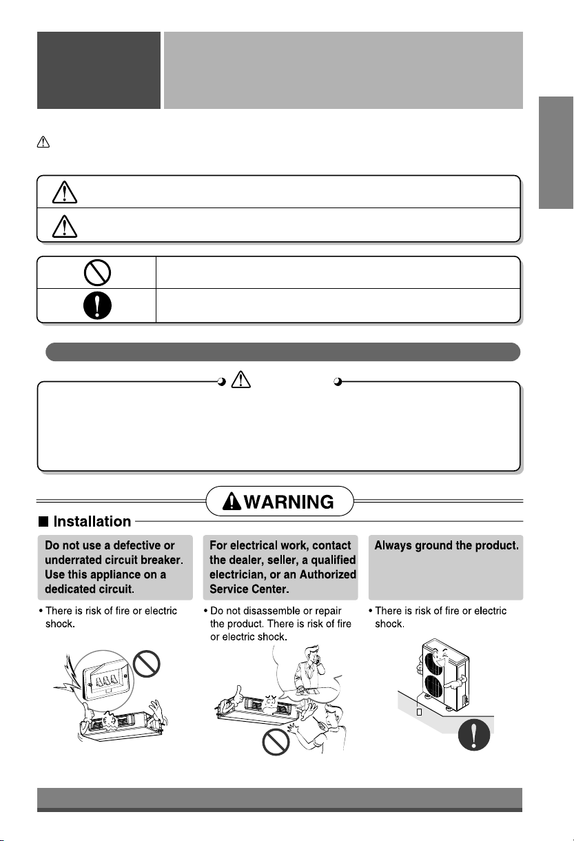
WARNING
WARNING
n
Do not install, remove and reinstall the unit by yourself.
• Improper installation will cause water leakage, electrical shock, or fire. Please consult
authorized dealer or specialist for the installation work. Please note fault caused by improper
installation is not covered by warranty.
• Unit must be installed in an easily accessible area. Any additional cost required to hire a
special equipment to service the unit will be the responsibility of the customer.
3
Page 4
4
Page 5
ENGLISH
5
Page 6
6
Page 7
ENGLISH
7
Page 8
8
Page 9
Operating
Instructions
Operating Instructions
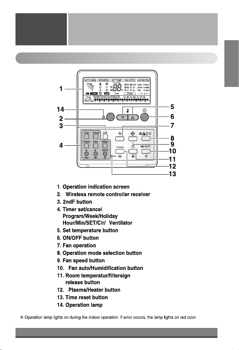
Name and Function of Remote Controller
ENGLISH
Optional feature.
•
•
(For number of COMP selection)
*
•
•
(optional)
9
(optional)
(optional)
Page 10
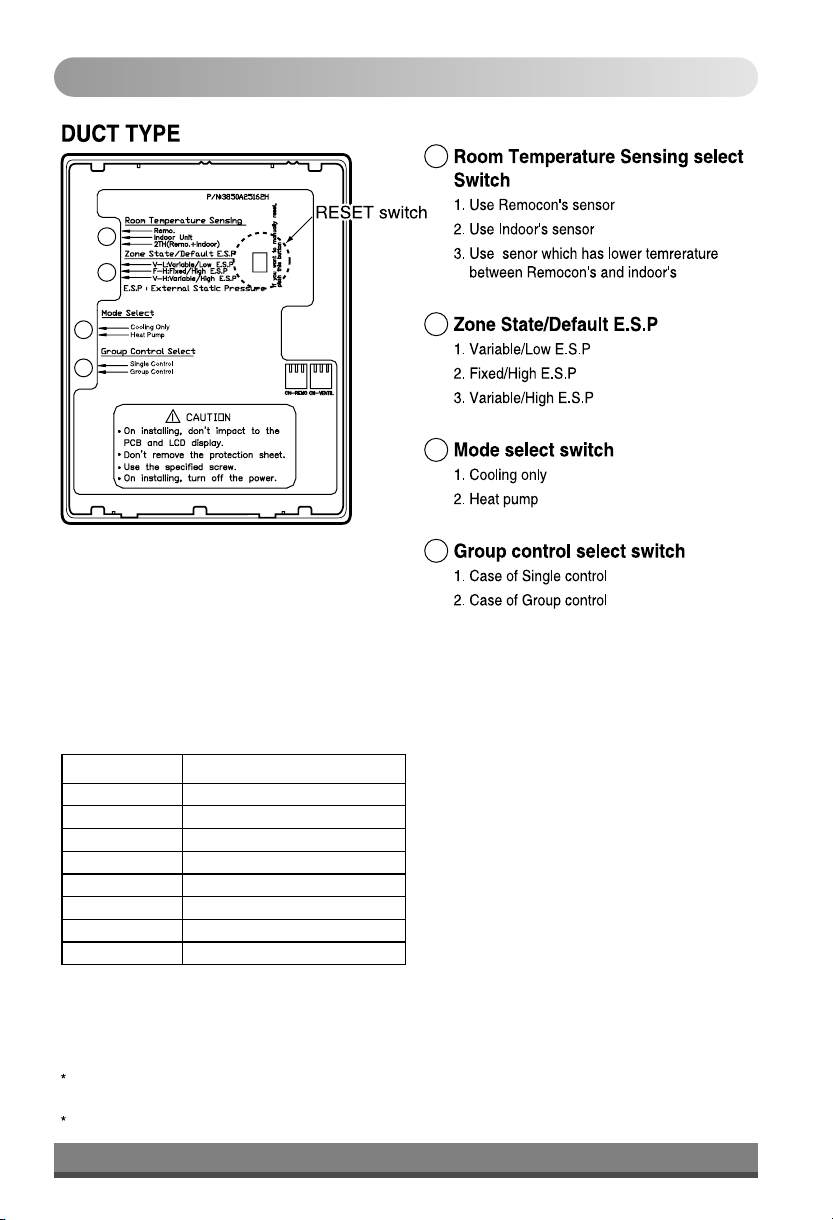
Information of Slide Switch
1
2
1
3
4
IDU Fan Speed Provision
Capacity
36K BTU/h
51K BTU/h
66K BTU/h
90K BTU/h
102K BTU/h
132K BTU/h
198K BTU/h
264K BTU/h
IDU Fan Speed
3 Speed (Hi, Low and Medium)
3 Speed (Hi, Low and Medium)
3 Speed (Hi, Low and Medium)
3 Speed (Hi, Low and Medium)
3 Speed (Hi, Low and Medium)
3 Speed (Hi, Low and Medium)
1 Speed (Hi)
1 Speed (Hi)
2
3
(optional)
4
(optional)
When changing the product selection switch and group control switch, you must press the reset switch to use
the changed selection.
For 198K BTU/H & 264K BTU/H keep room temperature sensing on Remo.
10
Page 11
Set the Current Time and a day of the Week
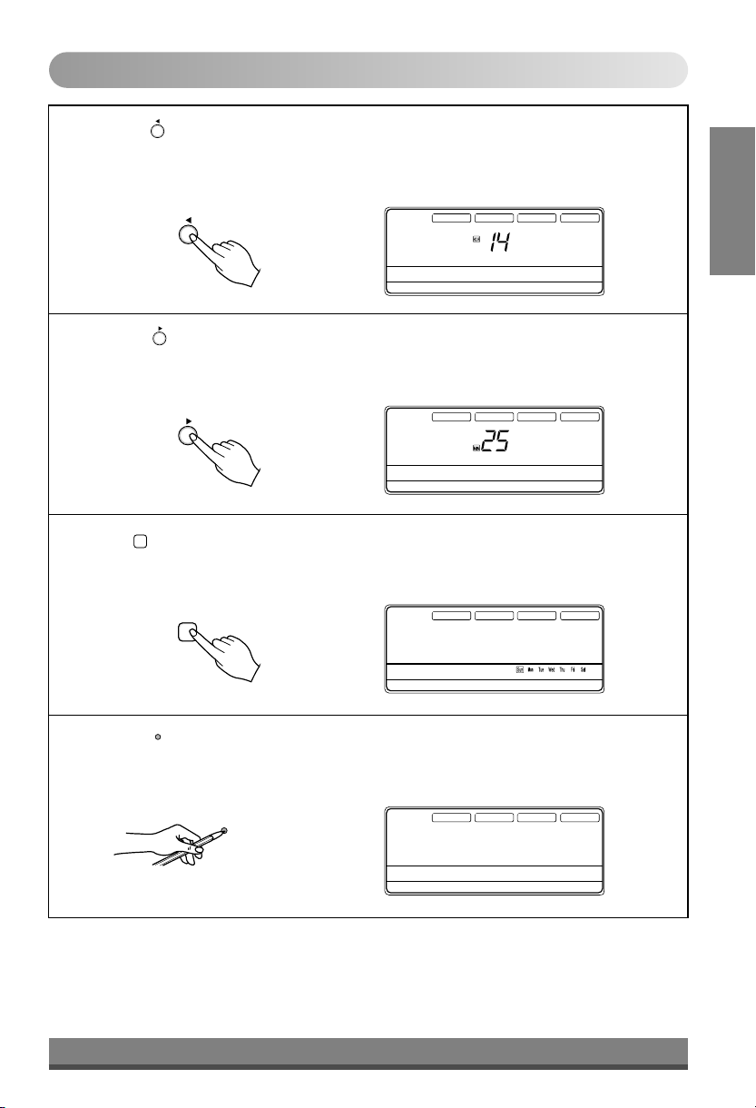
Press the ' ' button.
1
Hour
Each time the button is pressed, the number is changed from 00 to 23.
You can set the number of the current hour.
AUTO SWING
OPERATION
SET TEMP
Room Temp
Press the ' ' button.
2
Hour
Operation unit Program set
Timer
On
Off
01 03 05 07 09 11 13 15 17 19 21 23
Set no. Time
Min
Time
Each time the button is pressed, the number is increased from 00 to 59.
You can set the number of the current minute.
AUTO SWING
OPERATION
SET TEMP
Room Temp
Min
Week
Press ' ' button.
Operation unit Program set
Timer
On
Off
01 03 05 07 09 11 13 15 17 19 21 23
Set no. Time
Time
3
Each time the button is pressed, a day of the week is shifted from sunday to saturday.
You can set the day of the week.
Week
AUTO SWING
OPERATION
SET TEMP
Room Temp
Operation unit Program set
Timer
On
Off
01 03 05 07 09 11 13 15 17 19 21 23
Set no. Time
Time
FAN SPEED
HI
MED
LO
ZONE
FAN SPEED
HI
MED
LO
ZONE
FAN SPEED
HI
MED
LO
ZONE
AUTO
JET
AUTO
JET
AUTO
JET
SUB FUNCTION
Heater
Preheat
Defrost
Humidify
Filter
Out door
1 2 3 4
SUB FUNCTION
Heater
Preheat
Defrost
Humidify
Filter
Out door
1 2 3 4
SUB FUNCTION
Heater
Preheat
Defrost
Humidify
Filter
Out door
1 2 3 4
ENGLISH
Press the ' ' button.
RESET
4
If you want to reset the current time and a day of the week, click the Reset button.
AUTO SWING
OPERATION
RESET
11
Operation unit Program set
Timer
On
Off
01 03 05 07 09 11 13 15 17 19 21 23
Set no. Time
SET TEMP
Room Temp
Time
FAN SPEED
HI
MED
LO
ZONE
AUTO
JET
SUB FUNCTION
Heater
Preheat
Defrost
Humidify
Filter
Out door
1 2 3 4
Page 12
Weekly Programming
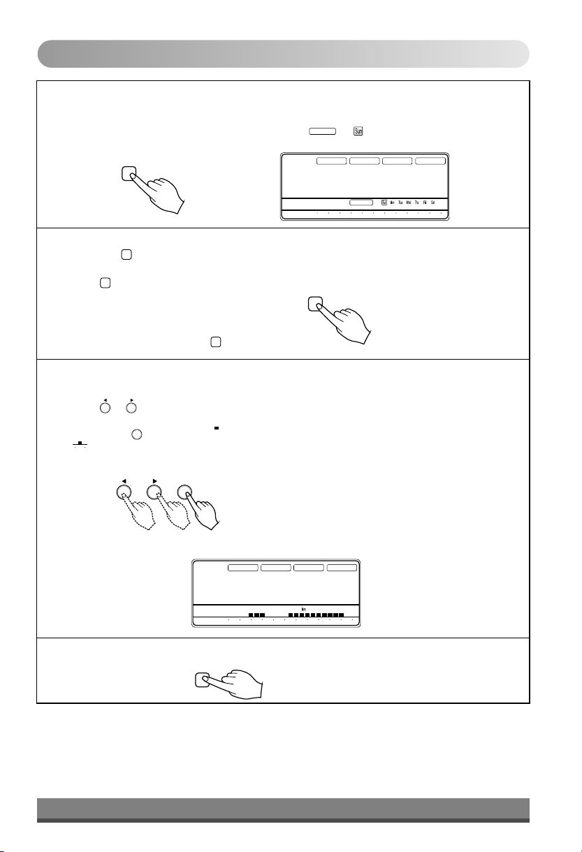
Press the Program button.
1
The remote controller is displayed like a picture. Then ' ', ' ' and '01' is blinked.
Program
Program set
AUTO SWING
OPERATION
SET TEMP
Room Temp
Operation unit
Timer
On
Off
01 03 05 07 09 11 13 15 17 19 21 23
Set no.
Time
Time
Program set
FAN SPEED
HI
MED
LO
ZONE
AUTO
JET
SUB FUNCTION
Heater
Preheat
Defrost
Humidify
Filter
Out door
1 2 3 4
Press the ' ' button.
Week
2
Week
Press button repeatedly until desired mode appears.
For example, if you want Thu, press button 4 times.
Week
Week
Select the time you want.
3
Press or button, then blinking letter is shown.
If you press button, then ' ' shape appears.
unit
05
' ' shape means that five o'clock is reserved.
Using below buttons, you can reserve time.
* For example, the air-conditioner is on 6,7,8 and 13~22 o'clock.
MinHour
SET/CLR
SET/CLR
MinHour
AUTO SWING
OPERATION
Operation unit
Timer
On
Off
01 03 05 07 09 11 13 15 17 19 21 23
Set no.
Time
SET TEMP
Room Temp
Time
Program set
FAN SPEED
HI
MED
LO
ZONE
AUTO
JET
SUB FUNCTION
Heater
Preheat
Defrost
Humidify
Filter
Out door
1 2 3 4
Press the Program button again to finish weekly programmining.
4
Program
12
Page 13
Holiday Setting
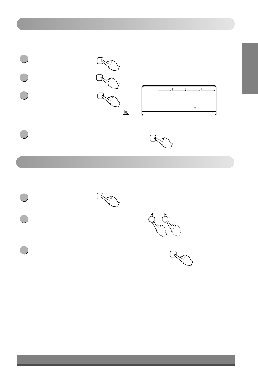
If Tuesday is a holiday in this week, you may set a holiday.
Press the Program button.
1
Program
ENGLISH
Press the Week button.
2
Select the Tuesday.
Press the Holiday button.
3
Week
Holiday
Then the remote controller will be displayed ' '.
The outside rectangular means holiday.
Press the Program button again to finish holiday setting.
4
Timer Setting (Delay start/Pre-set stop)
This function is used to turn on or turn off in several hours.
Press the Timer button
1
to turn Timer on or off.
2
Change the timer setting until the desired time is set.
If you want to cancel the timer setting, press the Cancel button.
3
Timer
AUTO SWING
OPERATION
SET TEMP
Room Temp
Time
Timer
On
Off
Set no.
Program
Time
Operation unit
Program set
01 03 05 07 09 11 13 15 17 19 21 23
MinHour
Cancel
FAN SPEED
HI
MED
LO
ZONE
AUTO
JET
SUB FUNCTION
Heater
Preheat
Defrost
Humidify
Filter
Out door
1 2 3 4
Note :- •
ON Timer is available when unit is OFF.
•
OFF Timer is available when unit is ON.
It starts counting time after Timer was set.
•
Timer can be set upto 24 hours.
•
13
Page 14
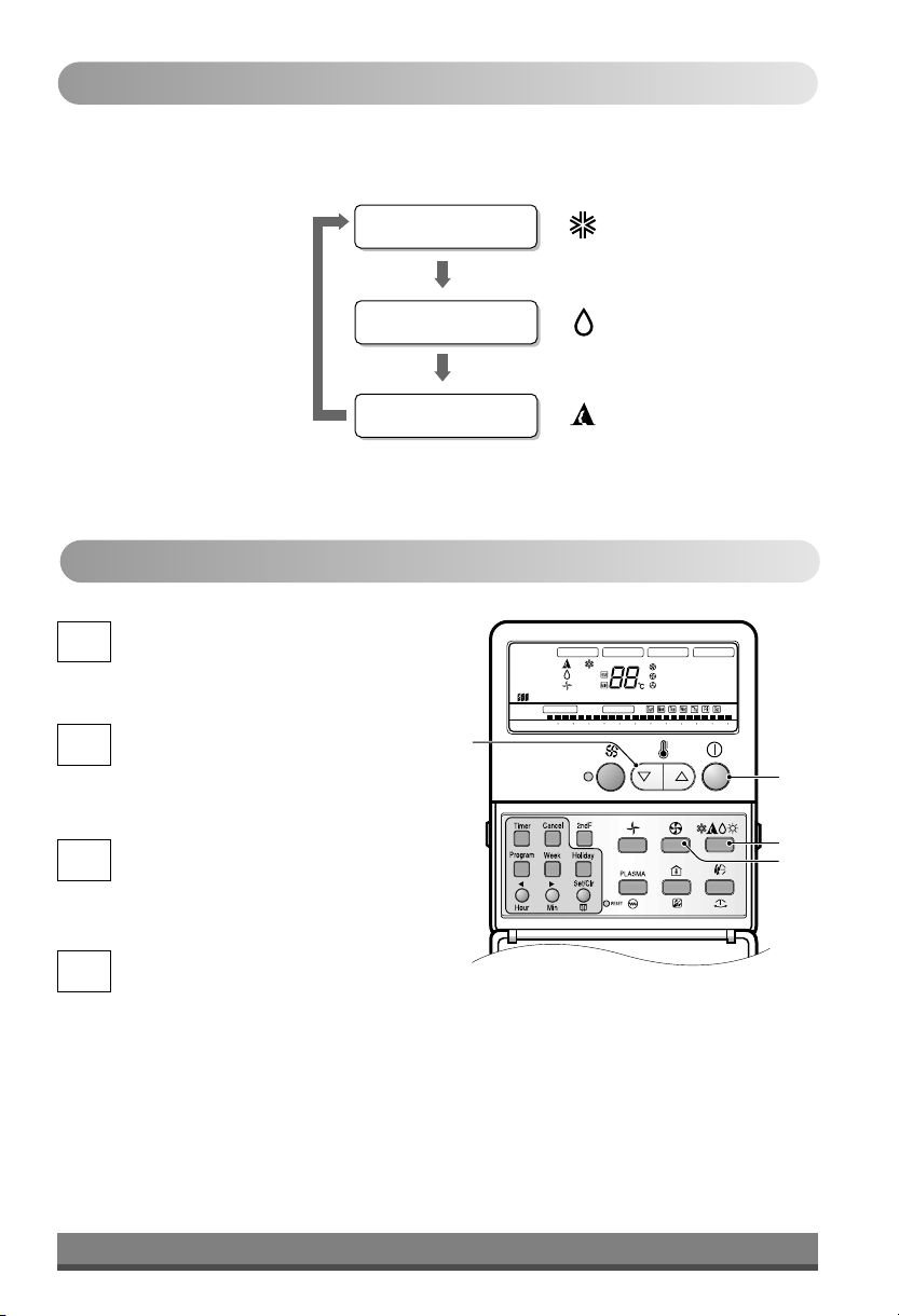
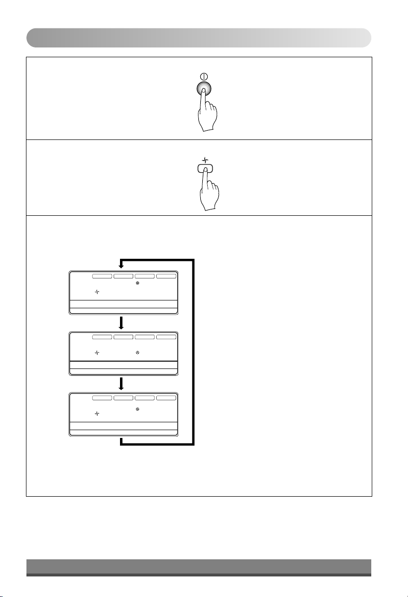
Operation Mode
Operation Procedure
On/Off Button
1st
Operation Mode Selection Button
2nd
Cooling Mode
Soft Dry Mode
Auto Mode
3
AUTO SWING OPERATION
Timer
On
Off
Set no. Time
SET TEMP
Room Temp
Time
Program set
Operation unit
01 03 05 07 09 11 13 15 17 19 21 23
FAN SPEED
HI
MED
LO
SUB FUNCTION
Filter Out door
1 2 3 4
1
Room Temperature Setting Button
3rd
Indoor Fan Speed Selection Button
th
4
2
4
14
Page 15
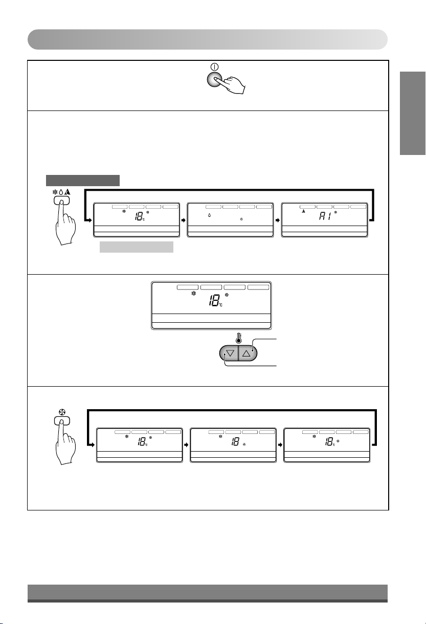
Cooling Operation Mode
Press the On/Off Button.
1
Select Cooling Operation.
2
Press the Operation Mode Selection Button.
Each time the button is pressed, the operation mode is shifted in the arrow direction.
COOLING MODEL
Operation Display
AUTO SWING
Set the temperature
3
lower than the room
temperature.
OPERATION
Operation unit Program set
Timer
On
Off
01 03 05 07 09 11 13 15 17 19 21 23
Set no. Time
Cooling Operation Soft Dry Operation
SET TEMP
Room Temp
FAN SPEED
SUB FUNCTION
HI
MED
LO
ZONE
Time
AUTO
JET
AUTO SWING
Timer
On
Set no. Time
AUTO SWING
Heater
Preheat
Defrost
Humidify
Filter
Out door
1 2 3 4
Off
Operation unit Program set
Timer
On
Off
01 03 05 07 09 11 13 15 17 19 21 23
Set no. Time
OPERATION
SET TEMP
Operation unit Program set
01 03 05 07 09 11 13 15 17 19 21 23
OPERATION
Room Temp
Time
SET TEMP
Room Temp
FAN SPEED
HI
MED
LO
ZONE
FAN SPEED
HI
MED
LO
ZONE
Time
AUTO
JET
SUB FUNCTION
AUTO
Heater
Defrost
JET
Filter
1 2 3 4
SUB FUNCTION
Heater
Preheat
Defrost
Humidify
Filter
Out door
1 2 3 4
Preheat
Humidify
Out door
AUTO SWING
OPERATION
Operation unit Program set
Timer
On
Off
01 03 05 07 09 11 13 15 17 19 21 23
Set no. Time
SET TEMP
Room Temp
FAN SPEED
HI
MED
LO
ZONE
Time
AUTO
JET
SUB FUNCTION
Heater
Defrost
Filter
1 2 3 4
Preheat
Humidify
Out door
Auto Operation
• The temperature can be set
within a range of 18°C ~ 30°C
by 1°C .
To raise the Temperature.
ENGLISH
Set the fan speed.
4
Operation Display
AUTO SWING
OPERATION
Operation unit Program set
Timer
On
Off
01 03 05 07 09 11 13 15 17 19 21 23
Set no. Time
• Select the fan speed in three steps- high, low, medium.
• The display shows high fan speed.
• Each time the button is pressed, the fan speed mode is shifted.
SET TEMP
Room Temp
FAN SPEED
HI
MED
LO
ZONE
Time
AUTO
JET
SUB FUNCTION
Heater
Defrost
Filter
1 2 3 4
AUTO SWING
Preheat
Humidify
Out door
OPERATION
Operation unit Program set
Timer
On
Off
01 03 05 07 09 11 13 15 17 19 21 23
Set no. Time
15
SET TEMP
Room Temp
FAN SPEED
HI
MED
LO
ZONE
Time
To lower the Temperature.
SUB FUNCTION
AUTO SWING
AUTO
Heater
Preheat
JET
Defrost
Humidify
Filter
Out door
1 2 3 4
OPERATION
Operation unit Program set
Timer
On
Off
01 03 05 07 09 11 13 15 17 19 21 23
Set no. Time
SET TEMP
Room Temp
FAN SPEED
HI
MED
LO
ZONE
Time
AUTO
JET
SUB FUNCTION
Heater
Defrost
Filter
1 2 3 4
Preheat
Humidify
Out door
Page 16
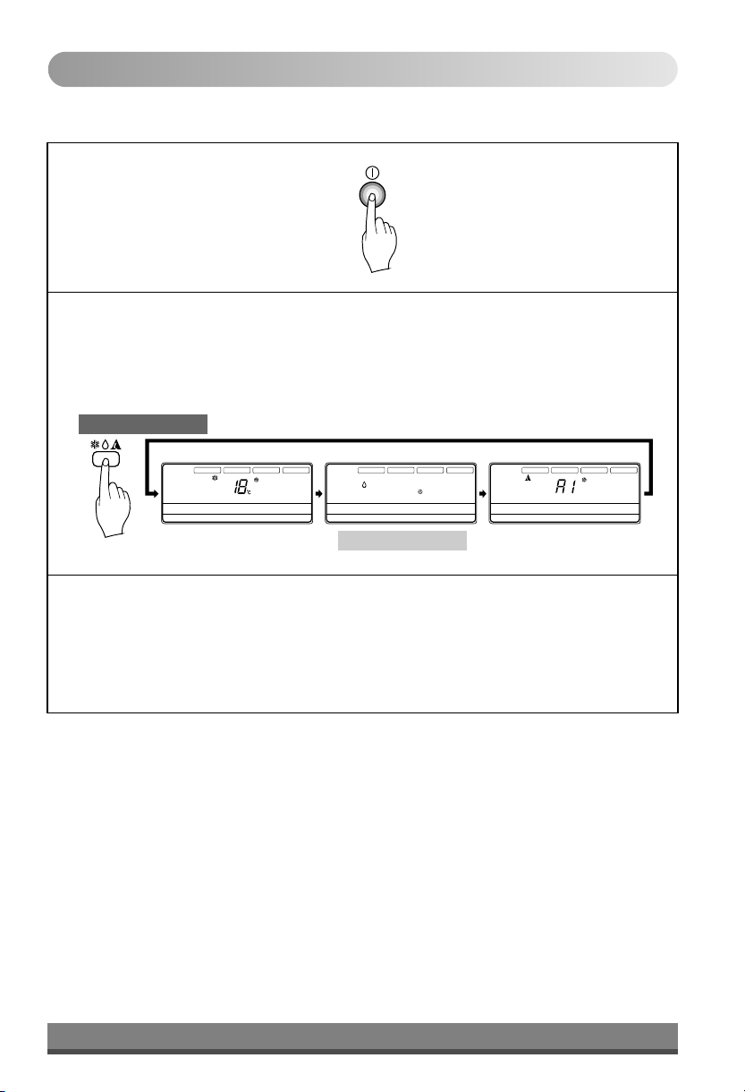
Soft Dry Operation Mode
This mode dehumidifies without overcooling.
Press the On/Off Button.
1
Select Soft Dry Operation.
2
Press the operation Mode Selection Button.
Each time the button is pressed, the operation mode is shifted in the arrow direction.
COOLING MODEL
Operation Display
AUTO SWING
OPERATION
Operation unit Program set
Timer
On
Off
01 03 05 07 09 11 13 15 17 19 21 23
Set no. Time
Cooling Operation
SET TEMP
Room Temp
FAN SPEED
HI
MED
LO
ZONE
Time
AUTO
JET
SUB FUNCTION
Heater
Defrost
Filter
1 2 3 4
AUTO SWING
Preheat
Humidify
Out door
OPERATION
Operation unit Program set
Timer
On
Off
01 03 05 07 09 11 13 15 17 19 21 23
Set no. Time
SET TEMP
Room Temp
FAN SPEED
HI
MED
LO
ZONE
Time
AUTO
JET
SUB FUNCTION
Heater
Preheat
Defrost
Humidify
Filter
Out door
1 2 3 4
AUTO SWING
Timer
On
Set no. Time
Soft Dry Operation Auto Operation
OPERATION
Operation unit Program set
Off
01 03 05 07 09 11 13 15 17 19 21 23
SET TEMP
Room Temp
FAN SPEED
HI
MED
LO
ZONE
Time
AUTO
JET
SUB FUNCTION
Heater
Defrost
Filter
1 2 3 4
Preheat
Humidify
Out door
During Soft Dry Operation.
3
• The indoor fan speed is automatically set to the low, so the shift of the indoor fan speed is
impossible because it's already being set to the best speed for Dry Operation by Micom
Control.
16
Page 17
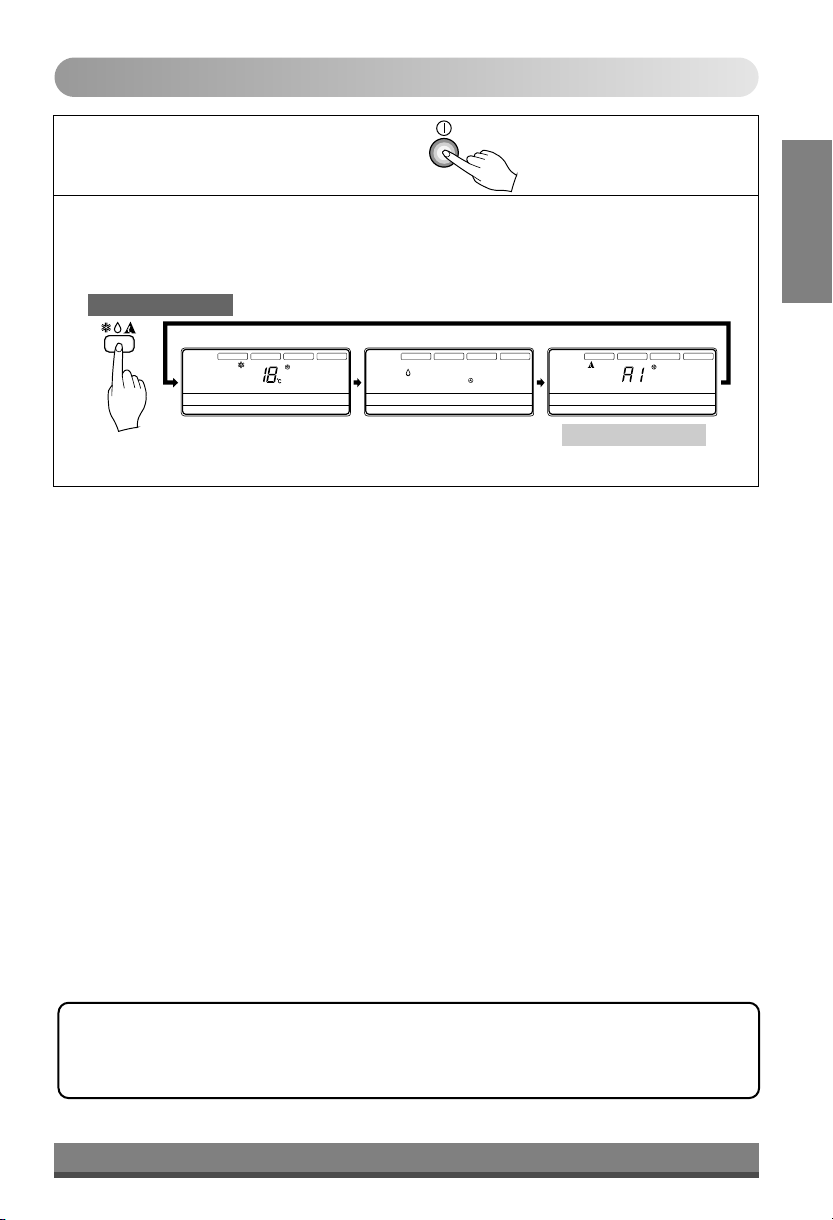
Auto Operation Mode
Press the On/Off Button.
1
To select Auto Operation , press the Operation Mode Selection button.
2
Each time the button is pressed, the operation mode is shifted in the direction of the arrow.
COOLING MODEL
Operation Display
AUTO SWING
OPERATION
Operation unit Program set
Timer
On
Off
01 03 05 07 09 11 13 15 17 19 21 23
Set no. Time
Cooling Operation
SET TEMP
Room Temp
FAN SPEED
HI
MED
LO
ZONE
Time
AUTO
JET
SUB FUNCTION
Heater
Defrost
Filter
1 2 3 4
AUTO SWING
Preheat
Humidify
Out door
OPERATION
Operation unit Program set
Timer
On
Off
01 03 05 07 09 11 13 15 17 19 21 23
Set no. Time
SET TEMP
Room Temp
FAN SPEED
HI
MED
LO
ZONE
Time
AUTO
JET
SUB FUNCTION
Preheat
Heater
Humidify
Defrost
Out door
Filter
1 2 3 4
AUTO SWING
Operation unit Program set
Timer
On
Off
01 03 05 07 09 11 13 15 17 19 21 23
Set no. Time
Soft Dry Operation Auto Operation
OPERATION
SET TEMP
Room Temp
FAN SPEED
HI
MED
LO
ZONE
Time
AUTO
JET
SUB FUNCTION
Heater
Defrost
Filter
1 2 3 4
ENGLISH
Preheat
Humidify
Out door
During Auto Operation:
qYou can switch the indoor fan speed.
qThe system will automatically switch from the cooling mode to the heating mode as the room temperature
and set temperature.(Heat pump model only)
17
Page 18
FAN Operation
Press the On/Off Button.
1
Press FAN Operation Button.
2
Each time Indoor Fan Speed button is pressed, the fan speed mode is shifted in the
3
arrow direction.
AUTO SWING
OPERATION
Operation unit Program set
Timer
On
Off
01 03 05 07 09 11 13 15 17 19 21 23
Set no. Time
SET TEMP
Room Temp
FAN SPEED
HI
MED
LO
ZONE
Time
AUTO
JET
SUB FUNCTION
Heater
Preheat
Defrost
Humidify
Filter
Out door
1 2 3 4
• Fan speed is high.
AUTO SWING
OPERATION
Operation unit Program set
Timer
On
Off
01 03 05 07 09 11 13 15 17 19 21 23
Set no. Time
AUTO SWING
OPERATION
Operation unit Program set
Timer
On
Off
01 03 05 07 09 11 13 15 17 19 21 23
Set no. Time
SET TEMP
Room Temp
SET TEMP
Room Temp
FAN SPEED
HI
MED
LO
ZONE
Time
FAN SPEED
HI
MED
LO
ZONE
Time
AUTO
JET
AUTO
JET
SUB FUNCTION
Heater
Preheat
Defrost
Humidify
Filter
Out door
1 2 3 4
SUB FUNCTION
Heater
Preheat
Defrost
Humidify
Filter
Out door
1 2 3 4
• Fan speed is low.
• Fan speed is medium.
* You can't set the temperature in Fan Operation mode. To exit this mode, press 'Operation Mode' button.
* Only high fan speed is available for 198K BTU/H & 264K BTU/H. Any other speed selection leads to
malfunctioning of the unit.
18
Page 19

Child Lock Function
This is the Function that any children cannot used to the air-conditioner.
Operation procedure
To set the Child-Lock Function
1
Press the Timer button and Minute Set button for three seconds. Then the
operation mode shift to child lock mode and it is displayed ‘CL’ in the operation
display.
When you press any button in this time, the remote controller is not converted to
any selected mode and the ‘CL’ is displayed in the remote controller for about
three seconds. But the Room Temperature function is operated in spite of child
lock mode.
2
To cancel the Child-Lock Function
Press the Timer button and Minute Set button for three seconds. Then the
child-lock mode is cancelled and the preselected mode is displayed in the
remote controller.
OPE RATI ON
SE T T EMP
Operation unit
Ti mer
On Of f
Se t no. Tim e
01 03 05 0 7 09 11 1 3 15 1 7 19 21 2 3
Program s et
Sun Mon Tu e
SU B F UN CT IO N
Wed
Thu
Fri Sa t
ENGLISH
19
Page 20

NEO PLASMA Purification Operation (optional)
AUTO SWING OPERATION
Timer
On
Off
Set no. Time
SET TEMP
Room Temp
Time
Program set
Operation unit
01 03 05 07 09 11 13 15 17 19 21 23
FAN SPEED
HI
MED
LO
SUB FUNCTION
Filter Out door
1 2 3 4
Press the Start/Stop button.
1
The unit will respond with a
beep.
Open the door of the remote
2
controller. Press the PLASMA
button.
Operation will start when the button
is pressed and stop when the button
is pressed again.
20
Page 21

Heating Operation (Heat Pump model only)
1
2
3
4
Select Heat mode
Press the Start/Stop button.
1
The unit will respond with
a beep.
ENGLISH
AUTO SWING OPERATION
Timer
On
Off
Set no. Time
SET TEMP
Room Temp
Time
Program set
Operation unit
01 03 05 07 09 11 13 15 17 19 21 23
FAN SPEED
HI
MED
LO
SUB FUNCTION
Filter Out door
1 2 3 4
Open the door of the remote controller. To select Heating
2
Operation, press the Operation Mode Selection button.
Each time the button is pressed, the operation mode is
shifted in the direction of the arrow.
Cooling
Auto
Healthy
Dehumidification
21
Heating
(Heat pump model only)
Page 22

Pressure Function
Sr.
KEY & MODE OPERATION
No.
* Low Pressure
Function
(LP Operation)
* High Pressure
Function
(HP Operation)
* Power Failure
Compensation
(Memory Function)
Error Diagnosis
– When Low Pressure operates, it
stops Comp as well as O/D Unit
after 10 sec of Comp Operation.
– If Comp Off occurs 3 times in 1
hour by L/P operation after the
first detection, Comp Off state has
been maintained.
– When High Pressure operates, it
stops Comp as well as O/D Unit
after 10 sec of Comp Operation.
– If Comp Off occurs 3 times in 1
hour by H/P operation after the
first detection, Comp Off state has
been maintained.
– Micom remembers the previous
running condition before power
failure, such as On/Off condition,
running mode, set temperature,
weekly programming etc.
ERROR RESET
Respective Comp No.
will blink.
Zone
Zone
1 2 3
1 2 3
Blinking
Respective Comp No.
will blink.
Blinking
Manual power reset.
Manual power reset.
Sr.
ERROR CODE DIAGNOSIS
No.
1
CH-01
2
CH-02
3
CH-06
4
CH-12
5
CH-09
6
CH-04
7
CH-14
Check room thermistor
Check pipe thermistor (CN-Pipe/In)
Check pipe thermistor (CN-Pipe/Out)
Check pipe thermistor (CN-Pipe/Med)
Check Option PCB (EPROM)
Check float sensor / Jumper
Check Sub PCB
22
DESCRIPTION
Recover after 5 seconds of operation when respective
thermistor healthy
Recover after 3 seconds of operation when respective
thermistor healthy
Recover after 3 seconds of operation when respective
thermistor healthy
Recover after 4 seconds of operation when respective
thermistor healthy
Check Interconnection of Option PCB and Power Reset
Recover after 4 minutes of operation when float sensor /
Jumper healthy
Check Interconnection of Sub PCB / Recover after
5 seconds of Healthy Interconnection
Page 23

Address Setup of Central Control
ENGLISH
23
Page 24

The Room Temperature Confirmation
24
Page 25

Operation Details
• Cooling Operation Mode
When the room temperature is higher than the set temperature, it operates in cooling mode at the set
temperature, the set fan speed, and then it will be in automatically turn off when the room temperature
reaches the set temperature +0.5¡C.
ROOM TEMP.
ENGLISH
OPERATION START
SET TEMP. +0.5 °C)
OPERATION STOP
SET TEMP. -0.5 °C)
INDOOR FAN
OUTDOOR FAN/COMP
: SETTING FAN SPEED : LOW COOL OPERATION : COMP ON : COMP OFF
More 3 minutes
Helpful information
Airflow speed and cooling capacity.
The cooling capacity indicated in the specification is
the value when the fan speed is set to high, and the
capacity will be lower at low or medium fan speed.
High fan speed is recommended when you wish to
cool the room quickly.
i
H gh
Sp
d
e
e
Self-Diagnosis Function
Remote Controller display will flash Error Code when a problem occurs, please contact your Dealer.
(for e.g., CH-01)
25
Page 26

Care and
maintenance
Caution: Before performing any maintenance, turn off the main power to the system.
Care and maintenance
Indoor Unit
Never use any of the followings:
Grille, Case, and Remote Control:
qTurn the system off before cleaning. To clean,
wipe with a soft, dry cloth. Do not use bleach or
abrasives.
Note:
Supply power must be disconnected before
cleaning the indoor unit.
Air outlet vent
Air filters
Air Filter:
The air filters behind Indoor unit
(the suction side) should be checked and cleaned
once every 2 weeks or more often if necessary.
q
• Water hotter than 40°C
Could cause deformation and/or
discoloration.
• Volatile substances
Could damage the surfaces
of the air conditioner.
Cleaning Tips:
q
Clean the filter with a vacuum or warm, soapy
1
water.
• If very dirty, wash with a solution of
detergent in lukewarm water.
• If hot water (50°C or more) is used, filter
may be deformed.
After washing with water, dry well in the shade.
2
Re-install the air filter.
3
S
I
N
N
E
R
S
C
O
G
U
N
I
R
B
e
n
e
z
n
e
C
L
B
A
R
E
R
G
Air outlet vent
Indoor Unit Dimensions (mm)
Dimension
Capacity
36K BTU/H
51K BTU/H
66K BTU/H
90K BTU/H
90K BTU/H
*
102K BTU/H 1625 1564 510 65 660 30 294 1220 304
102K BTU/H 1625 1562 510 65 688 30 294 1220 304
*
132K BTU/H 1765 1705 597 55 692 30 294 1220 304
198K BTU/H
264K BTU/H
is applicable for single piping model only.
*
• Slope of about 5-8 mm is to be provided at the
drain hole side of the indoor unit for proper
drainage.
• After installation the slope can be measured
using a sprit level.
A
B
D
E
F
C
1240
1180
365
57.5
480
1291
1230
565
57.5
680
1291
1230
485
57.5
600
1625 1564 510 65 660 30 294 1220 304
1625 1562 510 65 688 30 294 1220 304
1987
1930
755
55
865
2110
2050
920
55
1080
H
G
30
290
850
30
294
1025
30
294
1025
30
294
1260
22
294
1488
I
205
312
312
422
494
Slope 5-8 mm
26
Page 27

Outdoor Unit
The heat exchanger coils and panel vents of the outdoor unit should be checked regularly. If clogged
with dirt or soot, the heat exchanger and panel vents may be professionally steam cleaned.
Note:
Dirty or clogged coils will reduce the operating efficiency of the system and cause higher operating costs.
Outdoor Unit
D
W
(Side)
D
(Rear)
W
ENGLISH
H
Indoor Unit
H
W
Dimension
Capacity
36K BTU/H
51K BTU/H
66K BTU/H
90K BTU/H
90K BTU/H
*
102K BTU/H
102K BTU/H
*
132K BTU/H
132K BTU/H
132K BTU/H
198K BTU/H
264K BTU/H
is applicable for single piping model only.
*
W D H W D H
IDU
1180
1 1
1230
1 1
1230
1 1
1564
1 1
1562
1564
1 1
1562
1700
1
1700
1
1700
1
1985
1
2050
1
Air intake
vents
H
Air outlet
vents
D
Indoor Unit (mm)
480
600
600
660
688
660
688
690
690
690
865
1080
AIR F ILTER
ODU
295
370
370
460
460 906 600 11351 1
460
460 906 600 11351 1
460
460
460
595
640
1
2
1
3
2
A
I O
R U E
870
906
906
906
906
970
906
970
906
970
AIR IN TAKE V ENTS
TL T
V
E
N
TS
(For 198K & 264K Units)
Outdoor Unit (mm)
320
406
406
600
600
570
406
670
406
570
655
1135
1135
1135
1135
1310
1135
1310
1135
1310
Control Cover
Connecting Wire
Connection Pipe
Drain Hose
REMOTE
CONTROLLER
CONTROL
BOX
27
Page 28

When the air conditioner is not going to be used for a long time.
When it is not going to be used for
Operate the air conditioner on Air circulation
1
mode (Refer to page 15) for 2 to 3 hours.
• This will dry out the internal parts.
Turn off the circuit breaker.
2
Turn off the circuit breaker when the air conditioner
is not going to be used for a long time.
Dirt may collect and may cause a fire.
a long time.
CAUTION
CAUTION
Operation Tips
Do not overcool the room.
This is not good for the health
and wastes electricity.
Do not let direct sunshine
enter the room when the air
conditioner is in operation.
nCheck that the air inlet and outlet of the
indoor/outdoor unit are not blocked.
Helpful information
The air filters and your electiric bill.
If the air filters become clogged with dust, the
cooling capacity will drop, and 6% of the
electricity used to operate the air conditioner will
be wasted.
Keep blinds or curtains
closed.
When the air conditioner is to
be used again.
Make sure that the doors
and windows are shut tight.
Avoid opening doors and
windows as much as possible
to keep the cool air in the
room.
Clean the air filter regularly.
Blockages in the air filter
reduce the airflow and lower
cooling and dehumidifying
effects. Clean at least once
every two weeks.
Ventilate the room
occasionally.
Since windows are kept
closed, it is a good idea to
open them and ventilate the
room now and then.
28
Page 29

Troubleshooting
Tips
Before you call for service...
Troubleshooting Tips! Save time and money!
Check the following points before requesting repairs or service.... If the malfunction persist, please contact your
dealer.
Case Explanation See page
The air conditioner does not
operate.
The room has a peculiar odor.
It seems that condensate is
leaking from the air Conditioner.
Air conditioner does not operate
for about 3 minutes when restart.
Does not cool or heat effectively.
The air conditioner operation is
noisy.
Crack sound is heard.
Remote control display is faint, or
no display at all.
l
Have you made a mistake in timer operation?
l
On first starting, the indoor unit operates in
fifteen seconds.
l
Has the fuse blown or has the circuit breaker
been tripped?
l
Check power supply for single/reverse phase,
voltage imbalance.
l
Check that this is not a damp smell exuded by
the walls, carpet, furniture or cloth items in the
room.
l
Condensation occurs when the airflow from the
air conditioner cools the warm room air.
l
This is the protector of the mechanism.
l
Wait about three minutes and operation will
begin.
l
Is the air filter dirty? See air filter cleaning
instructions.
l
The room may have been very hot when the
room air conditioner was first turned on. Allow
time for it to cool down.
l
Has the setting temperature been set
incorrectly?
l
Are the indoor unit's air inlet or outlet vents
obstructed?
l
For a noise that sounds like water flowing.
-This is the sound of freon flowing inside the air
conditioner unit.
l
For a noise that sounds like the compressed air
releasing into atmosphere.
-This is the sound of the dehumidifying water
being processed inside the air conditioning
unit.
l
This sound is generated by the
expansion/contraction of the inlet grille, etc. due
to changes of temperature.
l
Has the circuit breaker been tripped?
8
-
-
-
-
16
10
-
-
-
ENGLISH
NOTE
WATER RESISTANT: The outdoor side of this appliance is WATER RESISTANT.
The indoor side is not water resistant and should not be exposed to excess
water.
29
Page 30

31
After reading this manual, keep it in a place easily accessible to the user for future reference.
installing.
switch to desired mode position on
• To set up the mode, adjust the slide
the two thermistors.
- 2 TH: Sensing the lower temperature of
• On installing, turn off the main power.
• Use the specified screw.
• Don't remove the protection sheet.
and LCD display.
• On installing, don't impact to the PCB
CAUTION
indoor Unit.
- Indoor Unit: Sensing the intake air into
- Remo: Sensing the room Temperature.
•
.
Selectable options are three as follows
Controller to set up the mode.
2 TH(Remo.+Indoor)
Indoor Unit
Remo.
Room Temp. Sensing
Slide Switch
• Open the rear cover of Remote
9. Two Thermistor system
• Ensure that the color of wire.
(Use soldering Iron or others)
• Remove the OP7 resistor.
wire them like above.
• Using the supplied Wired Remote Controller,
....
Connecting Cable(Local Supply)
#16
Main PCB
BR(GND)
BR(GND)
YL(SIGNAL)
YL(SIGNAL)
Block
Terminal(Local Supply)
Indoor Unit 16
#2
....
BR(GND)
YL(SIGNAL)
Main PCB
Connector Connector
Block
Terminal(Local Supply)
Indoor Unit 2
Main PCB
#1
BR(GND)
YL(SIGNAL)
(Standard)
Wired Remote Controller
Set no.Time
01 03 05 07 09 11 1315 17 19 2123
On
Off
Timer
Operation unit
Program set
12 34
Time
ZONE
LO
Filter
Out door
Humidify
JET
MED
Defrost
AUTO
HI
Heater
Preheat
PCB
Controller
Remote
OP7
BR(GND)
YL(SIGNAL)
Main PCB
RED(12V)
Connector
Indoor Unit 1
Room Temp
AUTO SWING OPERATION
FAN SPEED
SUB FUNCTION
SET TEMP
Slide Switch
BR(GND)
YL(SIGNAL)
RED(12V)
Block
Terminal(Local Supply)
ENGLISHENGLISHENGLISHENGLISH
and each Unit starts sequentially to prevent overcurrent.
It operates maximum 16 Units by only one Wired Remote Controller,
8. Group Control
Page 31

30
OPEN CLOSE
Vaccum pump
Closed
Outdoor unit
Closed
valve
3-way
Gas side
3-way valve
2-way valve/
Liquid side
Indoor unit
(Tightening torque: 1.8kg.m)
7. Disconnect the charge hose and fit the nut to the service port.
6. Tighten the valve stem nuts of the 2-way valve and 3-way valve.
hexagon wrench.
5. Remove the valve stem nuts, and fully open the stems of the 2-way and 3-way valves with a
76cmHg.
4. Vacuum the indoor unit and the connecting pipes until the pressure in them lowers to below -
service port by the charge hose.
3. Remove the service port nut, and connect the gauge manifold and the vacuum pump to the
2. After connecting the piping, check the joints for gas leakage with gas leak detector.
1. Confirm that both the liquid side valve and the gas side valve are set to the closed position.
on the compressor.
The air which contains moisture remaining in the refrigeration cycle may cause a malfunction
7. Air Purging of the Connecting Pipes and the Indoor Unit
Page 32

29
or equivalent.
3. Fix the pipings onto the wall by saddle
room.
trap prevent water from entering into the
along the exterior wall, and make the
2. Form the pipings gathered by taping
Trap
with gum type sealer.
around the pipings
Seal a small opening
from bottom to top.
1. Tape the Pipings and Connecting cable
above position of the Indoor Unit.
In case of the Outdoor Unit being installed
ENGLISHENGLISHENGLISHENGLISH
wall by saddle or equivalent.
along the exterior wall and fix it onto the
3. Form the pipings gathered by t aping
Connecting Cable from bottom to top.
2. Tape the Pip i ngs , dr ain hose an d
Insulation
Suction Pipe
below position of the Indoor unit.
In case of the Outdoor unit being installed
avoid swinging in the wind.)
dip it into water, and fix it on the wall to
keep distance from the ground. (Do not
hose, the end of the drain-outlet should
• If you want to connect an additional drain
with gum type sealer.
around the pipings
Seal a small opening
right pipings)
secure it with two Plastic Bands. (for the
unit w it h the Insulation material and
1. Wrap the connecting portion of indoor
4) Form the pipings
Page 33

28
• Do not cut or remove the grounding.
• To minimize the risk of electric shock, you must always plug into a grounded outlet.
10) Appliance mst be grounded.
• Proper starting power is not given to the compressor.
disturbance to the normal function of a overload protection device.
• Vibration of a magnetic switch, damage on the contact point there of, fuse breaking,
9) The following troubles would be caused by voltage drop-down.
8) Never fail to equip a leakage breaker where it is wet or moist.
(Particularly note the relation between cable length and thickness.)
7) Confirm that the cable thickness is as specified in the power sources specification.
marked on the name plate.
6) Be sure that the starting voltage is maintained at more than 90 percent of the rated voltage
5) Confirm that electrical capacity is sufficient.
4) Specification of power source
rise to burn-out of the wires.)
Check them and make sure that they are all tightly fastened. (If they are loose, it could give
loose from vibrations to which the unit is subjected during the course of transportation.
3) The screw which fasten the wiring in the casing of electrical fittings are liable to come
2) Provide a circuit breaker switch between power source and the unit.
of wiring, be guided by the circuit diagram pasted on the inside of control box cover.
1) Never fail to have an individual power specialized for the air conditioner. As for the method
After the confirmation of the above conditions, prepare the wiring as follows:
CAUTION
cord
Power supply
Cover control
position with the screw.
3. Refix the cover control to the original
Over 5mm
with the holder (clamper).
2. Secure the cable onto the control board
following.
the control board individually as
Cord Clamper
Connect the wires to the terminals on
by loosening a screw.
Terminal block
Outdoor unit
1. Remove the Cover control from the unit
Outdoor Unit
3) Connecting the cable to the
Page 34

27
3) For the cooling model, fix the other side of the clamp with a screw strongly.
2) First, fasten the steel clamp with a screw to the inner boss of control panel.
1) Arrange 2 power cables on the control panel.
2) Clamping of cables
ENGLISHENGLISHENGLISHENGLISH
Make sure that the screws of the terminal are free from looseness.
WARNING
If the supply cord is damaged, it must be replaced by a special cord or assembly availible from the manufacturer of its service agent.
0mm
(36K/60K)
1.25mm
2
2
L
AREA
CROSS-SECTIONAL
NORMAL
N/Y
G
3.5mm
2.5mm
Capacity
3 Phase
unit should be with the following specifications
The connecting cable connected to the indoor and outdoor
m
0
2 m
/ LY
N
60K BTU/h
36K BTU/h
NORMAL CROSS-SECTIONAL AREA
G
with the following specifications
The power cord connected to the outdoor unit should be
CAUTION
Please do the interconnection as per Interconnection Table in wiring diagram.
those of indoor unit respectively.
Ensure that the color of the wires of outdoor unit and the terminal No. are the same as
outdoor unit connection.
Connect the wires to the terminals on the control board individually according to the
1) Connecting cables to the Indoor Unit
6. Connecting Cables between Indoor and Outdoor Unit
Page 35

26
LP1
HP1
LP2
HP2
EARTH (GR)
ODM2 NEUTRAL (N)
ODM2 PHASE (L)
EARTH (GR)
ODM1 NEUTRAL (N)
ODM1 PHASE (L)
COMP 1 PHASE (R)
COMP 1 PHASE (Y)
COMP 1 PHASE (B)
COMP 2 PHASE (R)
COMP 2 PHASE (Y)
COMP 2 PHASE (B)
3Ø415 V
IDM PHASE T.O.P.
IDM PHASE T.O.P.
IDM PHASE (B)
IDM PHASE (Y)
IDM PHASE (R)
3Ø415 V
INDOOR CONTROL BOX
POWER SUPPLY
OUTDOORCONTROL BOX
POWER SUPPLY
3854A22012C
HP 1 LP 1
BL RD BL
HP-LP
From
LP HP
8 7
TERMINAL (B)
COMP1
From
R Y B
3 2
1
TERMINAL (A)
ODM
From
G P N
6 5 4
WH
RD
BK
T2
T3
T1
COMP(1)
TERMINAL (C)
BK BK BK
GR
BK
MOTOR
OUT(B)
MOTOR
OUT(A)
From C-Box Body
OUTDOOR WIRING DIAGRAM
EBY33415409
SUPPLY
3ø POWER
LP1 HP1 LP2 HP2
LP1
SUB PCB ASSEMBLY
32
LP1
HP1
33
HP1
LP2
34
LP2
HP2
35
HP2
GR
11
N
10
L
GR
9
N
8
L
R
17
18
Y
19
B
R
20
21
Y
22
B
NEUTRAL IN
4
3
PHASE IN ( B )
2
PHASE IN ( Y )
1
PHASE IN ( R )
Terminal No.
5
TP
4
TP
3
7
6
2
5
1
4
3
2
1
Terminal No.
CN-ZONE
BODY OF CONTROL BOX
ODM2 NEUTRAL
ODM2 PHASE
BODY OF CONTROL BOX
ODM1 NEUTRAL
ODM1 PHASE
COMP A PHASE (R)
COMP A PHASE (Y)
COMP A PHASE (B)
COMP B PHASE (R)
COMP B PHASE (Y)
COMP B PHASE (B)
Out Door & Control Box Connection Detail
IDM PHASE T.O.P.
IDM PHASE T.O.P.
IDM PHASE (B)
IDM PHASE (Y)
IDM PHASE (R)
NEUTRAL IN
PHASE IN ( B )
PHASE IN ( Y )
PHASE IN ( R )
In door & control box connection detail
ASSEMBLY
OPTION PCB
HIMED
COMP3 COMP2 COMP1
CN-OPTION
C -FLO
N A
T
CN-OUT
CN
- O
Z
N
E
CN-ROOM
CN-REMO CN-PTC
CN-PIPE
CONTROLLER
WIRED REMOTE
CN-H/P_B CN-L/P_B
BK
RD
CN-H/P_A CN-L/P_A
BK
RD
CN-N CN-L
BL
BR
PUMP
DRAIN
BL BL
LOW
CN-MOTOR1
CN-TAB
BL
OR
WH
WH
WH
CN-D/PUMP
CN-POWER
10A
RD
FUSE 250V
RY-D/PUMP
BK
MAIN PCB ASSEMBLY
CN-CC
CONTACT
DRY
32 33 34 35
TERMINAL
31
C1
30
C2
29
C3
28
HI
27
N
N
26
L
18
15
RELAY
L3
L2 L1
10 11
3ø MONITORING
CONTROL BOX WIRING DIAGRAM
IDM COMP1 COMP2 ODM1 ODM2
1 2 3 4
5 6 7
TP TP
20 21 22 8 9
17 18 19
COMP2
R Y B N
R Y B N
R Y B N
IDM
COMP1
R Y B N
N
Unit : 264K BTU/H
Wiring Diagram
Page 36

25
ENGLISHENGLISHENGLISHENGLISH
LP1
HP1
LP2
HP2
LP3
HP3
EARTH (GR)
ODM3 NEUTRAL (N)
ODM3 PHASE (L)
EARTH (GR)
ODM2 NEUTRAL (N)
ODM2 PHASE (L)
EARTH (GR)
ODM1 NEUTRAL (N)
ODM1 PHASE (L)
COMP 1 PHASE (R)
COMP 1 PHASE (Y)
COMP 1 PHASE (B)
COMP 2 PHASE (R)
COMP 2 PHASE (Y)
COMP 2 PHASE (B)
COMP 3 PHASE (R)
COMP 3 PHASE (Y)
COMP 3 PHASE (B)
3Ø415 V
IDM PHASE T.O.P.
IDM PHASE T.O.P.
IDM PHASE (B)
IDM PHASE (Y)
IDM PHASE (R)
3Ø415 V
INDOOR CONTROL BOX
POWER SUPPLY
OUTDOORCONTROL BOX
POWER SUPPLY
3854A22012B
(1ø,230V)
From C.BOX From C.BOX
BL
TERMINAL A
HP LP L N
1 2 3 4 5 6
LP SWITCH HP SWITCH
RD
RD
BK BK
From Control Box
From C-Box Body
CAPACITOR 1 CAPACITOR 2
ORANGE
RD BK
R Y B E
7 8 9 10 11 12
TERMINAL B
BLACK
ORANGE
YELLOW
YELLOW
BLACK
2
MOTOR
1
MOTOR
T/B1
EARTH
RD WH BK GR
T2
T1 T3
COMP
OUTDOOR WIRING DIAGRAM
EBY33415410
LP1
32
LP1
HP1
33
HP1
LP2
34
LP2
HP2
35
HP2
LP3
36
LP3
HP3
37
HP3
BODY OF CONTROL BOX
GR
ODM3 NEUTRAL
13
N
ODM3 PHASE
12
L
BODY OF CONTROL BOX
GR
ODM2 NEUTRAL
11
N
ODM2 PHASE
10
L
BODY OF CONTROL BOX
GR
ODM1 NEUTRAL
9
N
ODM1 PHASE
8
L
COMP A PHASE (R)
R
17
COMP A PHASE (Y)
18
Y
COMP A PHASE (B)
19
B
COMP B PHASE (R)
20
R
COMP B PHASE (Y)
Y
21
COMP B PHASE (B)
22
B
COMP C PHASE (R)
R
23
COMP C PHASE (Y)
24
Y
25
B
4
3
2
1
Terminal No.
5
TP
4
TP
3
7
6
2
5
1
4
3
2
1
-F
L
COMP C PHASE (B)
O
A
T
NEUTRAL IN
PHASE IN ( B )
PHASE IN ( Y )
PHASE IN ( R )
Out Door & Control Box Connection Detail
IDM PHASE T.O.P.
IDM PHASE T.O.P.
IDM PHASE (B)
IDM PHASE (Y)
IDM PHASE (R)
NEUTRAL IN
PHASE IN ( B )
PHASE IN ( Y )
PHASE IN ( R )
Terminal No.
In door & control box connection detail
SUB PCB ASSEMBLY
CN-ZONE
ASSEMBLY
OPTION PCB
HIMED
COMP3 COMP2 COMP1
CN-OPTION
C
N
CN-OUT
CN Z
- O E
N
CN-ROOM
CN-REMO CN-PTC
CN-PIPE
CONTROLLER
WIRED REMOTE
CN-H/P_C CN-L/P_C
BK
RD
CN-H/P_B CN-L/P_B
BK
RD
CN-H/P_A CN-L/P_A
BK
RD
CN-N CN-L
BL
BR
WH WH WH
PUMP
DRAIN
LOW
CN-MOTOR1
CN-TAB
BL
OR
YL
WH
BL BL
CN-D/PUMP
CN-POWER
10A
RD
FUSE 250V
RY-D/PUMP
BK
MAIN PCB ASSEMBLY
CN-CC
CONTACT
DRY
LP1 HP1 LP2 HP2 LP3 HP3
20 21 22 23 24 25 8 9
12 13
32 33 34 35 36 37
TERMINAL
31
C1
30
C2
29
C3
28
HI
27
N
N
26
L
18
15
RELAY
L1
L2 L3
10 11
3ø MONITORING
N N N
B
Y
17 18 19
COMP2
COMP3
R Y B N
R Y B N R Y B N
B
B
Y
Y
R
R
R
CONTROL BOX WIRING DIAGRAM
SUPPLY
3ø POWER
IDM COMP1 COMP2 COMP3 ODM1 ODM2 ODM3
1 2 3 4
5 6 7
TP TP
R Y B N
IDM
COMP1
R Y B N
N
B
Y
R
Unit : 198K BTU/H
Wiring Diagram
Page 37

24
EBY43304431
ECN
GN/YL
GREEN/YELLOW BLUE
RD
RED
BK
BLACK
CN-H/P_1 CN-L/P_1
SUB PCB ASSEMBLY
CN-ZONE
ASSEMBLY
OPTION PCB
RD
CN-OUT
CN-OPTION
-
Z
O
N
COMP3 COMP2 COMP1
CN-TAB
CN-MOTOR1
LOW
MED
HI
BRBL
PUMP
DRAIN
BL BL
CN-N CN-L
MAIN PCB ASSEMBLY
CN-ROOM
CN-REMO CN-PTC
CONTROLLER
WIRED REMOTE
BLACK
BLACK
BLACK
1413
TERMINAL (C)
CN-CC
CN-PIPE
CONTACT
DRY
HP 1LP 1
BLACK
BK
BK
RD
9 10 11 127 8
CONTROL BOX
GN/YL
BODY OF THE
RD
UNIT
FROM OUTDOOR
HP/LP & GND INPUT
COMP1
(SIGNAL)
TO OUTDOOR
BL BR
CN-D/PUMP
10A
FUSE250V
RY-D/PUMP
CN-POWER
BL
RD
WH
BK
BL
RD
(1 & 2)
WH
INDOOR MOTOR
BK
3 4 5 6
BL
BL
BR
2(N)
BR
1(L)
TO OUTDOOR UNIT
INDOOR WIRING DIAGRAM
1Ø230 V
TO INDOOR
LPHPSNP
TERMINAL (B)
12
FROM INDOOR
G
6
9 111078
5
GND
GN/YL
GN/YL
BK
B
NGYR
4
BK
2 31
POWER SUPPLY
3Ø415 V
TERMINAL (A)
GREEN
WHITE
BROWN
3 CORE
3 CORE
5 CORE
YL
YELLOW
OR
ORANGEWHBR
C
L AT
ON-F
1.0 mm
2
2
2
SPECIFICATION
10,11, &12
7,8, & 9
1.5 mm
10 mm
1,2,3,4 & 5
WIRE NO.
NORMAL CROSS-SECTIONAL AREA
BL
GN
LP1/HP1
LP1/HP1
GND
COMP1
NEUTRAL
PHASE
NC
GND IN
NEUTRAL IN
PHASE IN ( B )
PHASE IN ( Y )
PHASE IN ( R )
11
9
10
IN door motor
6
5
4
3
2
1
OUTDOORINDOOR
GREY
GREY
LP1/HP1
1
10 12
LP1/HP1
9
GND
8
COMP1
7
6
5
4
3
278
1
Terminal No.
S
C
1
NEUTRAL
PHASE
POWER SUPPLY
3Ø415 V
In door & Out door connection detail
R
MOTOR MOTOR
S
C
2
2
CAPACITOR
CAPACITOR
GREY
GREY
R
BLYLRD
L1
L2
RELAY
3ø MONITORING
15
18
28L325
RD
RD
YL
RD
OUTDOOR WIRING DIAGRAM
RD
BL
YL
BK
Magnetic Contactor(1)
T1 T3
T2
A1
Contactor
1
Magnetic
A2
L2
L3
L1
WH
BKL1RD
L2
L3
COMP(1)
Unit : 132K BTU/H (1 ODU - Single Piping)
Wiring Diagram
Page 38

23
ENGLISHENGLISH
EBY43304424
GREEN
WHITE
BROWN
YL
YELLOW
OR
ORANGEWHBR
BL
GN
GN/YL
GREEN/YELLOW BLUE
RD
RED
BK
BLACK
CN-H/P_2 CN-L/P_2
BK
CN-H/P_1 CN-L/P_1
SUB PCB ASSEMBLY
CN-ZONE
CN-N CN-L
RD
BK
9 10 11 127 8
RD
BL
RD
UNIT
FROM OUTDOOR
COMP2
(SIGNAL)
COMP1
TO OUTDOOR
BRBL
ASSEMBLY
OPTION PCB
3 CORE
3 CORE
5 CORE
LP/HP2(FOR UNIT2)
LP/HP2(FOR UNIT2)
LP/HP1(FOR UNIT1)
LP/HP1(FOR UNIT1)
COMP2(FOR UNIT2)
COMP1(FOR UNIT1)
GND
NEUTRAL
PHASE
NC
GND IN
NEUTRAL IN
PHASE IN ( B )
PHASE IN ( Y )
PHASE IN ( R )
2
2
2
5
4
4
IN door motor
3
3
6
8
7
12
11
10
9
8
7
OUTDOORINDOOR
BLRD
CN-OUT
CN-
F
L
OAT
CN-OPTION
C -
N
ZO
NE
LOW
MED
COMP3 COMP2 COMP1
HI
MAIN PCB ASSEMBLY
CN-ROOM
CN-REMO CN-PTC
CONTROLLER
WIRED REMOTE
3,4 & 5
1.0 mm
1,2 & 6
1.5 mm
10 mm
SPECIFICATION
12
10115
9
6
5
4
3
8
7
2
1
Terminal No.
7,8,9,10 & 11
WIRE NO.
NORMAL CROSS-SECTIONAL AREA
(SIGNAL)
(HP/LP)
INDOOR
INDOOR
INDOOR
FROM
TO
FROM
G
TERMINAL B
3 4 5 6
1 2
BK
9
LP/HP2
TB2
LP/HP2
BK
LP/HP1
LP/HP1
COMP2
COMP1
C/B BODY
NEUTRAL
PHASE
POWER SUPPLY
3Ø415 V
In door & Out door connection detail
BK
11
11
2
ORANGE
CAPACITOR1CAPACITOR
BLACK
YELLOW
ORANGE
S
S
C
C
R
R
YELLOW
1
2
CN-PIPE
GN
TERMINAL A
10 11
12
GN GN
BK
8
8
RD
4
YL
5
BL
6
A1
L3
L2 L1
RELAY
3ø MONITORING
15
18
A2
RD
RD
20
20
7
RD
TB1
T3
BLACK
MOTOR MOTOR
PUMP
DRAIN
CN-MOTOR1
CN-D/PUMP
BL BL
CN-TAB
RY-D/PUMP
BL BR
10A
FUSE250V
CN-POWER
BL
RD
(1 & 2)
WH
INDOOR MOTOR
BK
3 4 5 6
BL
BL
CN-CC
CONTACT
DRY
INDOOR
SWITCH
SWITCH
TO
HP2
LP2
RD
YL BL BK
RD
7 8 9
RD
7
34
RD
RD
YL BL BK
RD
1 2 3
T1 T2 T3
CONTACTOR
MAGNETIC
L1 L2 L3
RD
WH BK
T2
T1
COMP.2
G
TERMINAL B
35
34
TB2
BK
11
2
YELLOW
BR
2(N)
BR
1(L)
BODY OF THE CONTROL BOX
GN/YL
TO OUTDOOR UNIT
INDOOR WIRING DIAGRAM
POWER SUPPLY
3ø 415V
(SIGNAL)
(HP/LP)
INDOOR
INDOOR
FROM
FROM
L N
3 4 5 6
1 2
BK
9
BK
11
RD
20
ORANGE
CAPACITOR1CAPACITOR
BLACK
YELLOW
ORANGE
S
S
C
C
R
R
1
2
MOTOR MOTOR
GN
TERMINAL A
12
GN GN
BK
8
4
5
6
L3
L2 L1
RELAY
3ø MONITORING
15
18
RD
20
TB1
BLACK
7 8 9
10 11
7
RD
YL BL BK
1 2 3
8
RD
YL
BL
A1
T1 T2 T3
CONTACTOR
MAGNETIC
L1 L2 L3
A2
7
RD
T2
T3
COMP.1
SWITCH
SWITCH
HP1
LP1
RD YL BL BK
RD
35
RD
34
RD
RD
34
RD WH BK
T1
OUTDOOR WIRING DIAGRAM
Unit :132K BTU/H (2 ODU)
Wiring Diagram
Page 39

22
EBY43304426
GREEN
WHITE
BROWN
4 CORE
5 CORE
5 CORE
2
2
2
LP/HP2
LP/HP2
LP/HP1
LP/HP1
COMP2
COMP1
GND
NEUTRAL
PHASE
NC
GND IN
NEUTRAL IN
PHASE IN ( B )
PHASE IN ( Y )
PHASE IN ( R )
OUTDOORINDOOR
YL
YELLOW
OR
ORANGEWHBR
1.0 mm
1.5 mm
10 mm
SPECIFICATION
12 18
17
101116
9
15
6
5
IN door motor
4
3
8
11
7
10
9
2
8
7
1
6
5
4
3
3Ø415 V
2
1
Terminal No.
BL
GN
GN/YL
GREEN/YELLOW BLUE
RD
RED
BK
BLACK
CN-H/P_2 CN-L/P_2
BK
RD
SUB PCB ASSEMBLY
CN-ZONE
ASSEMBLY
OPTION PCB
BLRD
CN-OUT
CN
-F
LOA
T
CN-OPTION
CN-ZONE
CN-MOTOR1
LOW
MED
COMP3 COMP2 COMP1
HI
MAIN PCB ASSEMBLY
CN-ROOM
CN-REMO CN-PTC
CONTROLLER
WIRED REMOTE
15,16,17&18
7,8,9,10 & 11
1,2,3,4 & 5
WIRE NO.
NORMAL CROSS-SECTIONAL AREA
Magnetic Contactor(2)
LP/HP2
LP/HP2
LP/HP1
LP/HP1
COMP2
COMP1
C/B BODY
NEUTRAL
PHASE
POWER SUPPLY
In door & Out door connection detail
POWER SUPPLY
3Ø415 V
Y R
B
NG
6
23 1
4
TERMINAL (A)
5
GND
3
1
2
GN/YL
28
BK
BK
RD
BL8YL
BK
7
9
BK
Magnetic Contactor(1)
11
T3
T1
T2
Contactor
B
Magnetic
L1 L2
L3
WH
BK
RD
V
U
COMP(2)
T3
11
A1
A2
RD
BL
U
W
CN-CC
CN-PIPE
CONTACT
DRY
1Ø230 V
TO INDOOR
FROM INDOOR
G
12
911 1078
GN/YL
27
YL
YLT2BLT1RD
BK
BK
A1
Contactor
Magnetic
A2
L1 L2AL3
20
WH
BK
RD
V
W
COMP(1)
CN-H/P_1 CN-L/P_1
BK
RD
BL
RD
CN-N CN-L
BRBL
PUMP
DRAIN
BL BL
CN-TAB
CN-D/PUMP
RY-D/PUMP
BL BR
10A
FUSE250V
CN-POWER
UNIT
FROM OUTDOOR
9 10 11 127 8
COMP2
(SIGNAL)
COMP1
TO OUTDOOR
BL
RD
(1 & 2)
WH
INDOOR MOTOR
BK
3 4 5 6
BL
BL
BR
2(N)
BR
1(L)
BODY OF THE CONTROL BOX
GN/YL
TO OUTDOOR UNIT
INDOOR WIRING DIAGRAM
LP 1
HP 1
LP 2HP 2
30
30
TERMINAL (B)
BL YL RD
4
5
6
L1
L3
L2
RELAY
20
15
RD
3ø MONITORING
18
28
25
BL
BL
21
21
38
TERMINAL (D)
16 15
To Indoor
38
1920 18 17
7
RD
11
BK
RD
7
13
14
TERMINAL (C)
BK
BK
BK
BK
MOTOR
MOTOR
OUT(A)
OUT(B)
OUTDOOR WIRING DIAGRAM
Unit : 132K BTU/H
Wiring Diagram
Page 40

21
EBY43304427
GREEN
WHITE
BROWN
4 CORE
5 CORE
5 CORE
2
2
LP/HP2
LP/HP2
LP/HP1
LP/HP1
COMP2
COMP1
GND
NEUTRAL
PHASE
NC
GND IN
NEUTRAL IN
PHASE IN ( B )
PHASE IN ( Y )
PHASE IN ( R )
OUTDOORINDOOR
YL
YELLOW
OR
ORANGEWHBR
1.0 mm
1.5 mm
10 mm
2
SPECIFICATION
LP/HP2
12 16
LP/HP2
15
LP/HP1
101114
LP/HP1
9
13
6
5
IN door motor
4
3
COMP2
8
11
COMP1
7
10
9
2
8
PHASE
7
1
6
5
4
3
3Ø415 V
2
1
Terminal No.
In door & Out door connection detail
BL
GN
GN/YL
GREEN/YELLOW BLUE
RD
RED
BK
BLACK
SUB PCB ASSEMBLY
CN-ZONE
ASSEMBLY
OPTION PCB
BLRD
CN-TAB
CN-OUT
CN
- OAF
L T
CN-OPTION
N
-
ZC
ONE
CN-MOTOR1
LOW
MED
COMP3 COMP2 COMP1
HI
MAIN PCB ASSEMBLY
CN-ROOM
CN-REMO CN-PTC
CONTROLLER
WIRED REMOTE
13,14,15 &16
7,8,9,10 &11
1,2,3,4 & 5
WIRE NO.
NORMAL CROSS-SECTIONAL AREA
Magnetic Contactor(2)
C/B BODY
NEUTRAL
POWER SUPPLY
3Ø415 V
Y R
B
23 1
4
TERMINAL (A)
3
1
2
RD
BL8YL
BK
7
9
11
T3
T1
T2
Contactor
2
Magnetic
L1 L2
L3
WH
BK
RD
V
U
W
COMP(2)
NG
A1
A2
1Ø230 V
TO INDOOR
POWER SUPPLY
G
6
5
911 1078
GND
GN/YL
GN/YL
BK
28
BK
27
YL
YLT2BLT1RD
BK
Magnetic Contactor(1)
T3
11
Contactor
Magnetic
L1 L21L3
WH
BK
RD
BL
V
U
COMP(1)
CN-CC
CN-PIPE
CONTACT
DRY
FROM INDOOR
TERMINAL (B)
12
BK
A1
4
A2
L1
20
20
RD
W
15
RD
5
BRBL
BL YL RD
6
L2
18
CN-H/P_2 CN-L/P_2
BK
RD
CN-H/P_1 CN-L/P_1
BK
RD
BL
RD
CN-N CN-L
PUMP
DRAIN
BL BL
CN-D/PUMP
RY-D/PUMP
BL BR
10A
FUSE250V
CN-POWER
BR
UNIT
FROM OUTDOOR
9 10 11 127 8
COMP2
(SIGNAL)
COMP1
TO OUTDOOR
BL
RD
(1 & 2)
WH
INDOOR MOTOR
BK
3 4 5 6
BL
BL
2(N)
BR
1(L)
BODY OF THE CONTROL BOX
GN/YL
TO OUTDOOR UNIT
INDOOR WIRING DIAGRAM
LP 1HP 1
30
38
TERMINAL (C)
BK
9
3 4
BK
11
2
L3
RELAY
3ø MONITORING
28
25
BL
BL
21
21
7
7
14 13
To Indoor
BK
11
ORANGE
CAPACITOR1CAPACITOR
BLACK
YELLOW
ORANGE
YELLOW
R
S
S
2
C
C
R
1
MOTOR MOTOR
BR
BR
LP 2HP 2
30
38
TERMINAL (D)
16 15
To Indoor
1
2
BLACK
OUTDOOR WIRING DIAGRAM
ENGLISHENGLISH
Unit :102K BTU/H
Wiring Diagram
Page 41

20
EBY43304432
GN
GREEN
WHITE
BROWN
BL
YL
YELLOW
OR
ORANGEWHBR
GN/YL
GREEN/YELLOW BLUE
RD
RED
BK
BLACK
CN-H/P_1 CN-L/P_1
SUB PCB ASSEMBLY
CN-ZONE
CN-N CN-L
BK
RD
CONTROL BOX
GN/YL
BODY OF THE
RD
BRBL
ASSEMBLY
OPTION PCB
RD
CN-OUT
C O
N-
FL AT
CN-OPTION
C
N
-Z
ONE
LOW
MED
COMP3 COMP2 COMP1
HI
MAIN PCB ASSEMBLY
PUMP
DRAIN
BL BL
CN-TAB
CN-MOTOR1
CN-D/PUMP
10A
RY-D/PUMP
BL BR
FUSE250V
CN-POWER
BL
RD
WH
BK
CN-REMO CN-PTC
CN-ROOM
CONTROLLER
WIRED REMOTE
3 CORE
1.0 mm
2
3 CORE
2
5 CORE
2
SPECIFICATION
LP1/HP1
5
LP1/HP1
GND
6
COMP1
3
NEUTRAL
2
PHASE
1
NC
12
GND IN
11
NEUTRAL IN
10
PHASE IN (B )
9
PHASE IN (Y )
8
PHASE IN (R )
7
OUTDOORINDOOR
3,4 & 5
1,2 & 6
1.5 mm
6.0 mm
7,8,9,10 & 11
WIRE NO.
NORMAL CROSS-SECTIONALAREA
LP1/HP1
LP1/HP1
9104
GND
8
COMP1
7
6
}}
IN Door Motor
5
4
3
NEUTRAL
2
PHASE
1
POWER SUPPLY
3Ø415 V
TerminalNo.
In door &Out door connection detail
INDOOR
TO
G
TERMINAL B
TB2
BK
11
2
YELLOW
CN-CC
CN-PIPE
CONTACT
DRY
(SIGNAL)
(HP/LP)
INDOOR
FROM
3 4 5 6
BK
9
BK
11
CAPACITOR1CAPACITOR
ORANGE
S
C
R
2
(1 ,230V)ø
INDOOR
TO INDOOR
FROM
L N
1 2
RD
20
ORANGE
TERMINAL A
GN GN
BK
8
L3
L2 L1
RELAY
ø
18
15
RD
BLACK
YELLOW
S
R
1
TB1
C
BLACK
MOTOR MOTOR
BR
GN
10 11
12
8
RD
4
YL
5
BL
6
3 MONITORING
20
7
RD
T
U
R
NP
I
01 11 12
D
N
9
7 8
BL
BL
BL
BR
UNIT
O O T OO
/ &
R M U D
F
HP LP G
RT O
COMP1
TDOO
S N )
( IG AL
O U
R
BL
RD
5 6
O R O O
WH
ND O M T
I
3 4
2(N)
UNIT
)
OR
1(L
TDO
TO OU
POWER SUPPLY
3 415V
ø
RD YL BL BK
7 8 9
7
RD
RD
YL BL BK
1 2 3
T1 T2 T3 A1
CONTACTOR
MAGNETIC
L1 L2 L3 A2
RD WH BK
L2
L3
L1
SWITCHLPSWITCH
HP
RD
35
RD
34
RD
34
COMP.
Unit : 90K & 102K BTU/H (1 ODU - Single Piping)
Wiring Diagram
Page 42

19
EBY43304421
GN
GREEN
WHITE
BROWN
BL
OR
RD
OR
BL
OR
COMMON
3 CORE
3 CORE
5 CORE
BL
YL
YELLOW
OR
ORANGEWHBR
LB-E0552QC/5.5 TON
YL
BK
BL
BK
1.0 mm
2
1.5 mm
2
3.5 mm
2
SPECIFICATION
LB-E0422QC/4 TON
BK
LB-G0307QC/3 TON
YL
HI SPEED MEDIUM SPEED LOW SPEED
MODEL
WIRE COLOR FOR SPEED
Indoor Motor Connection Detail
3,4 & 5
1,2 & 6
7,8,9,10 & 11
WIRE NO.
NORMAL CROSS-SECTIONAL AREA
GN/YL
GREEN/YELLOW BLUE
RD
RED
BK
BLACK
CN-N CN-L
SUB PCB ASSEMBLY
CN-ZONE
BL
BR
CN-H/P1 CN-L/P1
BK
RD
ASSEMBLY
OPTION PCB
CN-OPTION
N O TC
-FL A
C
N-
Z
ON
E
CN-OUT
CN-REMO CN-PTC
CONTROLLER
WIRED REMOTE
(SIGNAL)
(HP/LP)
INDOOR
TO
INDOOR
INDOOR
FROM
FROM
YL BR
MOTOR
GN/YL
INDOOR
PUMP
DRAIN
LOW
HIMED
MEETING HOUSING
BL BL
RD BL BK
COMP3 COMP2 COMP1
CN-MOTOR1
MAIN PCB ASSEMBLY
CN-ROOM
(1ø,230V)
TO INDOOR
CN-CC
CN-PIPE
DRY
CN-D/PUMP
RY-D/PUMP
OR
RD
CONTACT
CN-POWER
10A
FUSE 250V
CN-TAB
RD
RD
TO OUTDOOR
GN/YL
(SIGNAL) (HP/LP)
3 4 5 6
BL
BL
2(N)
BR
1(L)
BR
TO OUTDOOR UNIT
INDOOR WIRING DIAGRAM
POWER SUPPLY
3ø 415V
SWITCH LPSWITCH
HP
ENGLISHENGLISH
GND
HP/LP
HP/LP
COMP
NEUTRAL
PHASE
NC
GND IN
NEUTRAL IN
PHASE IN ( B )
PHASE IN ( Y )
PHASE IN ( R )
OUTDOORINDOOR
G
TERMINAL B
9
TB2
BK
11
GND
3
6
HP/LP
6
5
HP/LP
5
4
COMP
4
3
2
2
1
1
12
11
10
9
3Ø415 V
8
7
Terminal No.
2
NEUTRAL
PHASE
POWER SUPPLY
In door & Out door connection detail
BK
11
1
CAPACITOR
CAPACITOR
ORANGE
S
C
R
YELLOW
2
L N
3 4 5 6
1 2
GN GN
BK
8
BK
L3
L2 L1
RELAY
18
15
RD
20
ORANGE
BLACK
YELLOW
S
R
1
TB1
C
BLACK
MOTOR MOTOR
GN
TERMINAL A
10 11
12
8
RD
4
YL
5
BL
6
RD YL BL BK
RD
7 8 9
7
RD
YL BL BK
1 2 3
35
RD
34
RD
RD
34
T1 T2 T3 A1
CONTACTOR
3ø MONITORING
RD
20
7
MAGNETIC
L1 L2 L3 A2
RD
T3
RD WH BK
T2
T1
COMP.
OUTDOOR WIRING DIAGRAM
Unit : 51K / 66K BTU/H
Wiring Diagram
Page 43

3 CORE
3 CORE
5 CORE
2
2
2
GND
HP/LP
HP/LP
COMP
NEUTRAL
PHASE
NC
GND IN
NEUTRAL IN
PHASE IN ( B )
PHASE IN ( Y )
PHASE IN ( R )
EBY43304423
1.0 mm
1.5 mm
3.5 mm
SPECIFICATION
RD
12
14
13
11
10
1
9
8
7
3
2
1
OUTDOORINDOOR
18
11, 13 & 14
9,10, & 12
1,2,3,7 & 8
WIRE NO.
NORMAL CROSS-SECTIONAL AREA
(HP/LP)
TO INDOOR
HP SWITCH
LP SWITCH
INDOOR
TO
(1ø,230V)
INDOOR
TO INDOOR
FROM
POWER SUPPLY
3ø 415V
N G L N S G
7
8 9 10 11 12
TERMINAL A
TERMINAL B
RD
GND
3
HP/LP
6
HP/LP
5
COMP
4
2
PHASE
13 14
RD
NEUTRAL
TERMINAL C
BK
GR/YL
L3
L2 L1
TERMINAL C
BK
1
ORANGE
CAPACITOR
RELAY
18
15
RD
BK
RD
RD
YL
BL
BL
3ø MONITORING
RD
BK
T3
POWER SUPPLY
3Ø415 V
Terminal No.
In door & Out door connection detail
YELLOW
BLACK
1
MOTOR
POWER SUPPLY
3ø 415V
R S T
1 2 3
RD
YL
T1 T2 T3 A1
CONTACTOR
MAGNETIC
L1 L2 L3 A2
RD WH BK
T2
T1
COMP.
OUTDOOR WIRING DIAGRAM
INDOOR WIRING DIAGRAM
POWER SUPPLY
R S T
1 2 3
(SIGNAL) (HP/LP)
TO OUTDOOR
TO OUTDOOR UNIT
3 4 5 6
2(N)
1(L)
GN/YL
BR
BL
BR
BL
RD
RD
BR
BL
RD
BK
CN-H/P1 CN-L/P1
CN-N CN-L
SUB PCB ASSEMBLY
GN/YLRDBK
RED
BLACK
GREEN/YELLOW BLUE
BLYLOR
EBY43304422
YELLOW
ORANGE
WHBRGN
WHITE
BROWN
GREEN
CN-ZONE
CN-POWER
FUSE 250V
10A
CN-TAB
CN-D/PUMP
RY-D/PUMP
OR
RD
BL BL
DRAIN
PUMP
MAIN PCB ASSEMBLY
CN-MOTOR1
YL BR
RD BL BK
LOW
INDOOR
MOTOR
MED
HI
COMP3 COMP2 COMP1
GN/YL
CN-OUT
OPTION PCB
CN-OPTION
ASSEMBLY
C
N
-
Z
ON
N
-
F
LA T
OC
CN-CC
CN-PIPE
CN-ROOM
E
CN-REMO CN-PTC
3ø 415V
POWER SUPPLY
3ø 415V
N G L N
TO INDOOR
(1ø,230V)
CONTACT
DRY
INDOOR
FROM
S G
TO
INDOOR
WIRED REMOTE
CONTROLLER
11,13 & 14
1.0 mm
2
3 CORE
(HP/LP)
9,10 & 12
1,2,3,7 & 8
WIRE NO.
NORMAL CROSS-SECTIONAL AREA
1.5 mm
3.5 mm
SPECIFICATION
2
2
5 CORE
3 CORE
RD
T1 T2 T3 A1
YL
CONTACTOR
TERMINAL A
7
8 9 10
11 12
TO INDOOR
HP SWITCH
LP SWITCH
BL
RD
BK
RD
BL
YL
TERMINAL B
RELAY
L3
L2 L1
GR/YL
BK
TERMINAL C
13 14
RD
RD
RD
RD WH BK
L1 L2 L3 A2
MAGNETIC
3ø MONITORING
T2
RD
BK
18
15
RD
ORANGE
CAPACITOR
1
TERMINAL C
BK
NEUTRAL
PHASE
COMP
HP/LP
HP/LP
GND
6
4
3
5
2
1
13
10
14
12
11
9
GND
HP/LP
HP/LP
PHASE
NEUTRAL
COMP
OUTDOOR WIRING DIAGRAM
T1
COMP.
T3
BLACK
MOTOR
1
YELLOW
POWER SUPPLY
In door & Out door connection detail
3Ø415 V
Terminal No.
8
3
7
2
1
OUTDOORINDOOR
GND IN
PHASE IN ( B )
NEUTRAL IN
NC
PHASE IN ( Y )
PHASE IN ( R )
Unit : 36K BTU/H
Wiring Diagram
Page 44

17
indoor unit without any leakage.
• Ensure that water flows drain hose of
the evaporator.
• S pray one or two glasses of water upon
2. Checkthe drainage.
1. Removethe AirFilter.
1) Checking the Drainage
5. Checking the Drainage
ENGLISHENGLISH
3/4" 6.6kg.m
Torque wrench
(Smaller Dia.)
Liquid side piping
(Bigger Dia.)
Gas side piping
Outdoor unit
5/8" 6.6kg.m
1/2" 5.5kg.m
3/8" 4.2kg.m
1/4" 1.8kg.m
Pipe size Torque
wrench.
tightening follows the arrow on the
wrench, ensure the direction for
• When tightening the flare nut with torque
wrenchuntilthe wrenchclicks.
2. Finally, tightenthe flare nut with torque
fingers.
sufficientlytighten the flare nut with
1. Al ig n the c enter of t he p iping san d
Outdoor unit
1) Connecting the pipes to the
4. Connecting Pipes to the Outdoor Unit
Page 45

16
b. When supplying inert gas, be sure to open one end of piping.
2
0.05~0.1kg/cm G)
(Nitrogen gas: Supply pressure
inert gas. Note that excessive gas pressure will generate pinholes at brazed points.
a. This procedure is designed to prevent formation of oxidation film by filling piping with
CAUTION
Water enters Plaster enters
prevent water or plaster from entering piping.
When connecting piping on rainy days or making a through-hole in wall, take due care to
(keep piping away from dust) and airtight (avoid refrigerant leakage).
When connecting piping, be sure to keep piping dry(keep piping away from water), clean
8) R efrigerant piping(Flare piping)
the following:
will clog. The blowing of nitrogen gas (or carbonic gas) through 3-way valves is described in
gas) to prevent formation of oxidation film in copper piping; otherwise, the refrigerant circuit
thermal insulator with burner heat. While brazing, blow inert gas (nitrogen gas or carbonic
protect piping against heat with wet cloth to avoid damaging valve packing or burning
also serves to connect straight pipes, generally using ready-made sockets. While brazing,
perform brazing using ready-made elbow. Aside from this function, brazing
Perform brazing using ready-made elbow. Aside from this function, brazing
position of devices or of the building structure, piping distance or finishing appearance.
piping resistance. Bending is, however, necessary in some places by virtue of the installation
In refrigerant piping, bending (in particular, acute bending) must be minimized to reduce
7) Brazing
appropriate for the pipe diameter.
copper pipe is large in diameter (ø12.7, ø15.88 or ø19.05), bend pipe with bender. Use bender
this case, secure large R(radius) for the bend section and gradually bend pipe. If annealed
Annealed copper pipe with small diameter (ø6.35 or ø9.52) can be easily bent manually. In
6) Pipe bending
Page 46

15
again.
all round
thickness
Cracked Uneven
damaged
Inclined
Surface
Even length
the flared section and do flaring work
If flare is noted to be defective, cut off
黐 Compare the flared work with figure.
5) Check
ENGLISHENGLISH
= Improper flaring =
indicated dimension in the table above.
Firmly hold copper tube in a bar(or die) as
Inside is shining without scratches.
Smooth all round
3/4" 1.0~1.3
5/8" 0.8~1.0
Red arrow mark
Cone
Yoke
Handle
Clamp handle
Copper pipe
"A"
Bar
Bar
1/2" 0.5~0.8
3/8" 0.5~0.8
1/4" 0~0.5
Outside Diameter "A"
as shown below.
⬀ Carry out flaring work using flaring tool
n
4) Flaring work
work)
(Not possible to put them on after flaring
removal.
pipe/tube having completed burr
and outdoor units, than put them on
Remove flare nuts attached to indoor
n
3) Putting nut on
Copper tube
Flare nut
tubing.
in order to avoid to let burrs drop in the
downward direction as you remove burrs
Put the end of the copper tube/pipe to
n
cross section of pipe/tube.
Completely remove all burrs from the cut
n
2) Burrs removal
Point down
Reamer
Pipe
length.
Cut the cable 1.5m longer than the pipe
n
measured distance.
Cut the pipes a little longer than
n
indoor and the outdoor unit.
Measure the distance between the
n
purchased locally.
nUse the accessory piping kit or the pipes
1) Cut the pipes and the cable.
in the following procedure.
90➀
Slanted Uneven Rough
tube
Copper
flaring work. Carry out correct flaring work
Main cause of gas leakage is defect in
3-1. Preparation of Piping
3. Connecting Pipes to the Indoor Unit
Page 47

14
clamper
Cord
Cover control
Please check !!
in the control box and do earthing.
or more to the earthing terminal provided
2
Connect the cable of diameter 1.6mm
• Earthing work
• Use the cord clamper to fix the cord.
Control terminal board
Main terminal board
connection.
• Remove the control cover for wiring
OUTDOOR UNIT
• Use the cord clamper to fix the cord.
(Remove crews)➀
Wiring Connection is put)
(On which the Electric
Control box cover
1
indoor and outdoor unit.
electrical connection between the
• Remove the control box cover for
INDOOR UNIT
1
outdoor unit
and the
the indoor unit
cord between
Connection
control cord
Remote
Cord clamper
A
view
A
Control box
Control terminal board
125A
80A
63A
50A
40A
32A
32A
25A
MCB Rating (3 Phase)
WIRING CONNECTION
264K BTU/h
198K BTU/h
132K BTU/h
102K BTU/h
90K BTU/h
66K BTU/h
51K BTU/h
36K BTU/h
Capacity
• Capacity of circuit breaker
Indoor
Outdoor
fitted.
disconnect all supply lines must be
A disconnection device to adequately
between the power source and the unit.
• Use a recognized circuit breaker
conditioner.
Switch box
Circuit Breaker
power source
Main
supplying the current required by the air
• Select a power source that is capable of
requirements.
• All wiring must comply with local
the electrical wiring connection.
Perform the electrical wiring work according to
ELECTRICALWIRING
Page 48

13
Keep a maintenance space
n
ENGLISHENGLISH
Face of wall
Above 100Cm
Outdoor unit
Above 100Cm
Above 50Cm Above 50Cm
and withstand its vibrations.
and that can support the weight of unit
• A place where the unit shall be leveled
neighbors.
• A place where it shall not annoy the
get good ventilation.
• A place where the air conditioner can
nSelect the following location
conditions. Install the unit firmly in place.
Select a location that satisfies the following
Braze the connection pipes
Indoor
INSTALLATION OF OUT DOOR UNIT
increase in the vertical length of the pipe.
• U-trap is to be provided for every 5 mtr.
(See page 4 for details)
U-Trap
Use hard pipe
Braze the connection pipes
Outdoor
nAdd refrigerant if piping is over 7.5m.
joints.
• When piping work is finished, check all
drying.
Factory charged gas
• Perform air purge with R-22 or vacuum
• Braze the joints
Manual or Installation Guide.
Perform the work according to the Service
REFRIGERANT PIPING
Page 49

12
(Local supply)
2. Fix the remote control cord.
by ø3 tapping screws(Local supply).
1. Fix the cord clamps on the wall
CONTROL CORD
clamp
Cord
Lower notch
(Part B)
Push hand
Upper flange
(Local supply)
Tapping screw
Under plate
Upper notch
Face of wall
Remote
(Part A)
Remote
FIXING OF REMOTE
control unit
control cord
Switch box
Lower notch
control cord
Remote
(Local supply)
Screw
control unit
Remote
Under plate
Upper notch
Face of wall
3. Hook the remote control unit on the under plate.
2. Receive the remote control cord in the switch box.
plate on the wall, and be careful of deformation.
screws(Local supply). In this case, fit the under
1. Fix the under plate on the switch box by
PROCEDURE OF INSTALLATION
INSTALLED WITH THE CORD BURIED.
4. Hook the remote control unit on the under plate.
case(Part B).
this case, push the cord into the around of
3.Rout the cord as shown in the following figure. In
control box by nipper.
2. Make a slit (Part A) at the top side of the remote
screws (accessory).
1. Fix the under plate on the wall by self tapping
PROCEDURE OF INSTALLATION
box body
control
Remote
t
r
a
p
r
e
w
o
l
e
Front case
h
driver, etc.
using a screw
the box open
Lever carefully
T
WHEN THE REMOTE CONTROL BOX IS
INSTALLED WITH THE CORD EXPOSED.
WHEN THE REMOTE CONTROL BOX IS
DISASSEMBLING OF THE REMOTE CONTROLLER
2
and remote controller side.
numbers are matched on unit side
Make sure that wire and terminal
CN REMO
(Main board)
The maximum length of the cord is 100m.
If the length of the cord exceeds 50m, use a wire size greater than 0.5mm .
CN REMO
Remote controller
ELECTRICAL WIRING TO THE INDOOR UNIT
(The standard height is 1.2~1.5m high)
to prevent water droplets from running.
wall, provide a trap at the top of the cord
• If the remote control cord is secured to a
(Audio equipment, Television set, etc)
5cm away from other power cables.
electrical noise, place the cord at least
• To protect the remote control cord from
piping.
the refrigerant piping and the drain
• Keep the remote control cord away from
ROUTING OF THE REMOTE CONTROL CORD
higher or lower, display is difficult to see.
liquid crystal display. If this position is
• This remote controller equipped with
built in the indoor unit.
thermostat for temperature control is
• The room temperature sensor of the
customer approval.
• Select control position after receiving
water.
• Select places that is not splashed by
INSTALLATION OF THE REMOTE CONTROL BOX
be installed in such places away from direct sunlight and high humidity.
• A lthough the room temperature sensor is in the indoor unit, the remote control box should
POINT OF REMOTE CONTROLLER INSTALLATION
and cord correctly.
Install the remote control box
INSTALLATION OF REMOTE CONTROL BOX
Page 50

11
ENGLISHENGLISH
• For every 5 mitrs. increase in vertical length of the piping, U-Trap is to be provided.
Page 51

10
l Wiring Is the wiring connection correctly?
l Gas leakage Is the piping connection correctly?
l Drain Is the drainage smoothly and no sweating?
l Air distribution Is the air circulation good?
After all workings are finished, check the working and operation.
TEST AND CHECK
filter driers.
(From the Condenser outlet)
Liquid Line
Filter Drier
(To the Evaporator)
Liquid Line
match the flow direction indicator on the
The direction of flow of the refrigerant must
l
where they are accessable for servicing.
the respective indoor units at a position
No
Direction of the flow of the Refrigeran t
are to be fitted in the liquid line using flare nuts, near
l Filter Driers, recommended to be used with the unit,
Note :
l
Gas Side
quid pipe
insulation of li
l Insulate gas side pipe
REFRIGERANT PIPE
Gas pipe
Local supply)
Thermal insulator for refrigerant pipe
(Local Supply)
Hose crip for thermal insulator
insulator (Local supply)
Refrigerant pipe and thermal
Liquid pipe
INDOOR UNIT
All thermal insulation must comply with local requirement.
Insulate the joint and tubes completely.
5~7mm
WALL
Indoor Outdoor
THERMAL INSULATION
INSULATION, OTHERS
outdoor side.
Piping hole should be slightly slant to the
l
core drill.
Drill the piping hole with 70mm dia, hole
l
Page 52

9
C 20mm
B 40mm
U-Trap
B
A
C
A 70mm
= 10mmAq
Ex) External Pressure
(mmAq)
SP = External Pressure
C 2 x SP
B 2C
A 70mm
of intake air filter.
a water leakage caused by the blocking
• Install the P-Trap (or U-Trap) to prevent
Applied U-Trap Dimension
INCORRECT
CORRECT
allowed
Upward routing not
•
ENGLISHENGLISH
Drainage hole
Make sure to be closed.
pipe.
shall always be provided for the drain
(Local supply)
Unit
Drainage pipe
(Local supply)
Thermal insulator
inclination so water will drain out.
Lay the drain hose with a downward
Drainage hole
INCORRECT
5~8mm
Drainage hole
• 5mm or thicker formed thermal insulator
in any part.
Prevent any upward flow or reverse flow
inclination (1/50 to 1/100).
• Always lay the drain with downward
UNIT AND DRAIN PIPING
CAUTION FOR GRADIENT OF
CORRECT
Ceiling
installation.
• The unit must be horizontal or declined to the drain hose connected when finished
Front of view
2. Minimum thickness of the insulation for the connecting pipe shall be 5mm.
conditioner.
1. Install declination of the indoor unit is very important for the drain of the duct type air
CAUTION
Page 53

8
Tighten the nut and bolt to prevent unit falling.
CAUTION
M16
M16
M16
M16
Suspension bolt - W3/8 or M10
Nut - W3/8 or M10
Spring washer - M10
Plate washer - M10
Set anchor
•
(198K-264K)
(36K-132K)
bolts
5 Suspension
4 Nut
3 Spring washer
2 Plate washer
1 Set anchor
Local supply
Old building New building
washers.
using nuts, washers and spring
suspension bolts (adjust level roughly)
• Secure the installation plates onto the
anchor firmly.
• Mount the suspension bolts to the set
suspension bolts on the ceiling.
the suspension bolts for locking the
• Insert the set anchor and washer onto
of ceiling.
• Drill the hole for set anchor on the face
bolts.
•
Select and mark the position for fixing
Page 54

7
For 198K-264K
ENGLISHENGLISH
X 4
supply)
X 4
(Local
X 4
X 4
supply)
X 4
(Local
X 4
M10 Nut
M10 SP. washer
M10 washer
M10 washer
M10 SP. washer
M10 Nut
M16 WA SHER X 3 X 4
M16 SPR ING WA SHER X 3 X 4
M16 N UT X 3 X 4
performed.
• A place where service can be easily
vibration.
Drainage hole
5-8 mm
H
I
(G)
• A place where the unit can withstand its
that can support the weight of the unit.
• A place where the unit will be leveled and
POSITION OF CONSOLE BOLT
side as a figure for easy water drainage.
• Install the unit leaning to a drainage hole
• Apply a filter Accessory at air return hole.
CD
EF
duct to absorb unnecessary vibration.
• Apply a joint-canvas between the unit and
POSITION OF SUSPENSION BOLT
B
A
correctly.
Install the unit above the ceiling
nInstallation of Unit
2. Indoor unit installation
Page 55

6
*
is applicable for single piping model only.
1080
1310
1135
1310
1135
1310
1135
1135
1135
1135
655
906
406
970
670
906
406
970
570
906
600
906
600
906
406
906
406
870
320
Outdoor Unit (mm)
970
570
640
2
595
3
460
1
460
2
460
1
460 906 600 11351 1
460
460 906 600 11351 1
460
370
370
295
ODU
2050
865
690
690
690
688
660
688
660
600
600
480
1
1985
1
1700
1
1700
1
1700
1
1562
1564
1 1
1562
1564
1 1
1230
1 1
1230
1 1
1180
1 1
W D H W D H
IDU
Indoor Unit (mm)
264K BTU/H
198K BTU/H
132K BTU/H
132K BTU/H
132K BTU/H
*
102K BTU/H
102K BTU/H
*
90K BTU/H
90K BTU/H
66K BTU/H
51K BTU/H
36K BTU/H
Capacity
Dimension
CONTROLLER
REMOTE
(For 198K & 264K Unit)
S
T
VEN
E
UTL T
R O
I
A
H
BOX
CONTROL
AIR IN TAKE V ENTS
AIR F ILTER
Drain Hose
Connection Pipe
Connecting Wire
Control Cover
(Rear)
W
D
W
Indoor Unit
vents
Air outlet
H
vents
Air intake
(Side)
D
W
H
D
Outdoor Unit
Dirty or clogged coils will reduce the operating efficiency of the system and cause higher operating costs.
Note:
with dirt or soot, the heat exchanger and panel vents may be professionally steam cleaned.
The heat exchanger coils and panel vents of the outdoor unit should be checked regularly. If clogged
Outdoor Unit
Page 56

5
using a sprit level.
• After installation the slope can be measured
drainage.
Slope 5-8 mm
2110
2050
920
55
1080
22
294
1488
494
1987
1930
755
55
865
30
294
1260
422
1625 1562 510 65 688 30 294 1220 304
1625 1564 510 65 660 30 294 1220 304
1291
1230
485
57.5
600
30
294
1025
312
1291
1230
565
57.5
680
30
294
1025
312
1240
1180
365
57.5
480
30
290
850
205
G
F
H
I
C
A
B
D
E
drain hole side of the indoor unit for proper
• Slope of about 5-8 mm is to be provided at the
*
is applicable for single piping model only.
264K BTU/H
198K BTU/H
132K BTU/H 1765 1705 597 55 692 30 294 1220 304
*
102K BTU/H 1625 1562 510 65 688 30 294 1220 304
102K BTU/H 1625 1564 510 65 660 30 294 1220 304
*
90K BTU/H
90K BTU/H
66K BTU/H
51K BTU/H
36K BTU/H
Capacity
Dimension
Indoor Unit Dimensions (mm)
Air outlet vent
3
Re-install the air filter.
2
After washing with water, dry well in the shade.
may be deformed.
• If hot water (50°C or more) is used, filter
detergent in lukewarm water.
• If very dirty, wash with a solution of
water.
1
Clean the filter with a vacuum or warm, soapy
q
Cleaning Tips:
Air filters
once every 2 weeks or more often if necessary.
(the suction side) should be checked and cleaned
The air filters behind Indoor unit
Air Filter:
Air outlet vent
ENGLISHENGLISH
e
n
z
e
G
R
E
R
A
B
L
C
R
I
N
U
G
O
C
S
n
e
B
R
E
N
N
I
S
of the air conditioner.
Could damage the surfaces
• Volatile substances
discoloration.
Could cause deformation and/or
• Water hotter than 40°C
q
Never use any of the followings:
cleaning the indoor unit.
Supply power must be disconnected before
Note:
abrasives.
wipe with a soft, dry cloth. Do not use bleach or
qTurn the system off before cleaning. To clean,
Grille, Case, and Remote Control:
Indoor Unit
Caution: Before performing any maintenance, turn off the main power to the system.
Care and maintenance
maintenance
Care and
Page 57

4
line of ODU.
• 36K BTU/h model indoor liquid line 1/4" to be swaged to 3/8" liquid
length is on the basis of reliability.
• Capacity is based on standard length and maximum allowance
*
7.5
100
10
70
10
Outdoor unit
B
A
70
10
70
10
70
10
70
10
70
10
70
10
70
10
70
Indoor unit
10
60
10
40
Max.
(g/m)
refrigerant
*Additional
30
5
30
5
30
5
30
5
30
5
30
5
30
5
30
5
30
5
30
5
30
5
30
Max.
Elevation B(m)
5
10
5/8"
7.5
7.5
7.5
7.5
7.5
7.5
7.5
7.5
7.5
7.5
7.5
Standard Standard
Length A(m)
1-1/8"
1/2"
7/8"
5/8"
1-1/8"
1/2"
7/8"
1/2"
7/8"
5/8"
1-1/8"
1/2"
9/8"
5/8"
1-1/8"
1/2"
3/4"
1/2"
7/8"
1/2"
3/4"
3/8"
5/8"
Gas
Liquid
(Diameter : Ø)
Pipe Size
1
2
1
3
1
1
1
2
1
1
1 1
1
1
1 1
1
1
1
1
1
1
1
1
(nos)
(nos)
Unit
Unit
Outdoor
is applicable for single piping model only.
264K BTU/h
198K BTU/h
*
132K BTU/h
132K BTU/h
132K BTU/h
*
102K BTU/h
102K BTU/h
*
90K BTU/h
90K BTU/h
66K BTU/h
51K BTU/h
36K BTU/h
Capacity
Indoor
3) Piping length and the elevation
the wall, ceiling, fence or other obstacles.
• Ensure the spaces indicated by arrows from
discharged.
which could be affected by hot air
• There should not be any animals or plants
restricted.
that heat radiation from the condenser is not
direct sunlight or rain exposure, be careful
• I f an awning is built over the unit to prevent
2) Outdoor unit
H
Front
1000
1000600
Control box
(600X600)
Inspection hole
near the unit
• There should not be any heat source or steam
be good .
• The place where air circulation in the room will
electrical noise.
• The place where the unit is not affected by an
outdoor unit.
•The place shall easily connect with the
to get a slope to drain as figure.)
drainage.(Suitable dimension “H” is necessary
Front view
• The place shall allow easy water
• T he place where the unit shall be leveled.
the figure.
• The place shall be able to inspect the unit as
four times the indoor unit’s weight.
• The place shall easily bear a load exceeding
satisfies the following conditions.
Install the air conditioner in the location that
(unit: mm)
Top view
Select location
1) Indoor unit
1. Selection of the best location
2. Installation of Indoor, Outdoor Unit
Page 58

3
could cause an explosion.
• If gas leaks and accumulates in the area surrounding the unit, it
inflammable gas leaks.
Do not install the unit in a place where an
wet and damaged.
could drop from the unit and household goods could be
• If there is a defect in the drainage/piping work, water
according to the installation manual.
Perform the drainage/piping work securely
CAUTION
water due to a fire, electric shock, the unit falling, etc.
• The use of defective parts could cause an injury or leakage of
the installation work.
Be sure to use the part provided or specified parts for
in a fire or electric shock due to dust, water, etc.
panel if the outdoor unit are not attached securely, it could result
• If the electrical part cover if the indoor unit and/or the service
the service panel to the outdoor unit securely.
Attach the electrical part cover to the indoor unit and
shock.
incomplete electrical work, it could result in a fire or an electric
• If the capacit y of the power c ircuit is insuffic ient or there is
manual and be sure to use an exclusive circuit.
Perform electrical work according to the installation
fire, electric shock, the unit falling or a leakage of water.
• Incomplete installation could cause a personal injury due to
installation manual.
Perform the installation securely referring to the
installation is completed.
Check that the refrigerant gas do not leak after
• Incomplete connecting and fixing could cause fire.
of the wires is not applied to the sections.
the terminal board connecting sections so the stress
outdoor units securely and attach the wires firmly to
Use the specified wires to connect the indoor and the
causing injured.
• When installed in an insufficient strong place, the unit could fall
weight of the unit.
Install the unit securely in a place which can bear the
you purchased the unit or special installer.
the unit falling or a leakage of water. Consult the dealer from whom
• Incomplete installation could cause injury due to fire, electric shock,
Do not install it yourself (customer).
WARNING
ENGLISHENGLISH
place.
• After reading this manual, be sure to keep it together with the owner's manual in an accessible
Could lead to serious injury in particular environments when operated incorrectly.
Could lead to death, serious injury, etc.
CAUTION
WARNING
• The indications and meanings are as follows.
• Be sure to observe the cautions specified here as they include important items related to safety.
installing the air conditioner.
• Be sure to read "THE FOLLOWING SHOULD BE ALWAYS OBSERVED FOR SAFETY" before
• Please report to or take consent by the supply authority before connecting to the system.
1. The following should be always observed for safety
Page 59

2
9. Two Thermistor System ............................................................................. 31
8. Group Control ............................................................................................ 31
•
Gas-leak Detector
•
Hexagonal Wrench (4mm/5mm)
7. Air Purging of the Connecting Pipes and the Indoor Unit..................... 30
3) Form the pipings..........29
Outdoor Unit ................28
2) Connecting cables to the
•
Screw driver
Indoor Unit ...................27
1) Connecting cables to the
6. Connecting Cables between Indoor Unit and Outdoor Unit.................. 27
5. Checking the Drainage...............................................................................17
(Inner Dia...............25mm)
•
Additional Drain hose
the Outdoor Unit ..........17
1) Connecting the pipes to
4. Connecting Pipes to the Outdoor Unit.....................................................17
Insulation materials
installing 5.5 TR
•
Pipe is to be used for
•
Flaring Tools set
•
•
Insulated drain hose
Liquid side ............. 1/4", 1/2", 5/8", 3/4"
•
Pipes: Gas side ..... 3/4", 5/8", 7/8", 1-1/8"
1) Preparation of Piping...15
3. Connecting Pipes to the Indoor Unit........................................................15
•
Hole core drill (ø70mm)
Electric drill
•
Screw driver
•
•
Level
5
•
Connecting cable
•
Four Type “A” screws
............................4
2) Indoor unit installation....
location
1)
Selection of the best
2. Installation of Indoor, Outdoor Unit........................................................... 4
Installation works Installation Parts Required tools
1.The following should be always observed for safety............................... 3
OUT-LINE OF INSTALLATION
Page 60

LG Electronics India Pvt. Ltd.
Regd. Office : A-27, Mohan Cooperative Industrial Estate, Mathura Road, New Delhi-110044.
Drain Hose
Connection Pipe
Connecting Wire
Control Cover
vents
Air outlet
vents
Air intake
(Rear)
Drain hose
Piping
Connecting wire
Control cover
(Rear)
Remote Controller
Air filters
Air outlet vents
(Side)
Air outlet vents
Air intake vents
(Side)
Air intake vents
Outdoor Unit
ENGLISH
Indoor Unit
personnel only.
• Installation work must be performed in accordance with national wiring standards by authorized
personnel only.
• When the power cord is wanted to replace, replacement work shall be performed by authorized
• Please read this instruction sheet completely before installing the product.
INSTALLATION INSTRUCTIONS
CEILING DUCT TYPE AIR CONDITIONERS
 Loading...