

LG LBUS3061BL, LBNK3661BL, LBNK3660BL, LBUK3660BL, LBUK4260BL Service Manual
...
Ceiling Duct Type
Air Conditioner
SERVICE MANUAL
MODELS: LBNS3061BL LBUS3061BL
LBNK3660BL LBUK3660BL
LBNK3661BL LBUK4260BL
LBNK4260BL LBUK4880BL
LBNK4261BL LBUL6080BL
LBNK4880BL LBUM7280BL
LBNK4881BL LBUM9080BL
LBNL6080BL LBUM1081BL
LBNL6081BL
LBNM7280BL
LBNM7281BL
LBNM9080BL
LBNM9081BL
LBNM1081BL

Contents
Functions .................................................................................................................................3
Product Specifications (Cooling & Heating)..........................................................................5
Dimensions ..............................................................................................................................7
Refrigeration Cycle Diagram ..................................................................................................9
Wiring Diagram ......................................................................................................................10
Operation Details ...................................................................................................................17
Installation of Indoor, Outdoor Unit .....................................................................................20
Cycle........................................................................................................................................34
Cycle Troubleshooting Guide ...............................................................................................37
Electronic Parts Troubleshooting Guide .............................................................................38
Electronic Control Device .....................................................................................................41
Exploded View and Replacement Parts List .......................................................................42
–2–
Functions
Indoor Unit
Operation ON/OFF by Remote controller
Sensing the Room Temperature
Room temperature control
Starting Current Control
Time Delay Safety Control
Indoor Fan Speed Control
Soft Dry Operation Mode
Auto Operation(Auto Change Over)
Deice (defrost) control (Heating)
Auto Restart
–3–
Hot-start Control (Heating)
• The indoor fan stops until the evaporator piping temperature will be reached at 28°C.
High head height Drain pump(Optional)
• A standard drain-head height of up to 700mm is possible.
Central Control(Optional)
•
It is operating individually or totally by central control function.
Group Control(Optional Wiring)
Radio Frequency Control (Optional)
•
Each controller can control 16 units and 8 controllers can connect.
•
It operates maximum 16 units by only one wired remote controller and each unit starts random to prevent overcurrent.
• Room temperature sensor. (Thermistor)
•
Maintains the room temperature in accordance with the Setting Temp.
• Indoor fan is delayed for 5 seconds at the starting.
• Restarting is inhibited for approx. 3 minutes.
• High, Med, Low
• Intermittent operation of fan at low speed.
• Although the air-conditioner is turned off by a power failure, it is restarted automatically previous operation mode after power supply.
• The setting temperature and desired operation mode are automatically set by fuzzy rule.
• Both the indoor and outdoor fan stops during defrosting.
• Hot start after defrost ends.
–4–
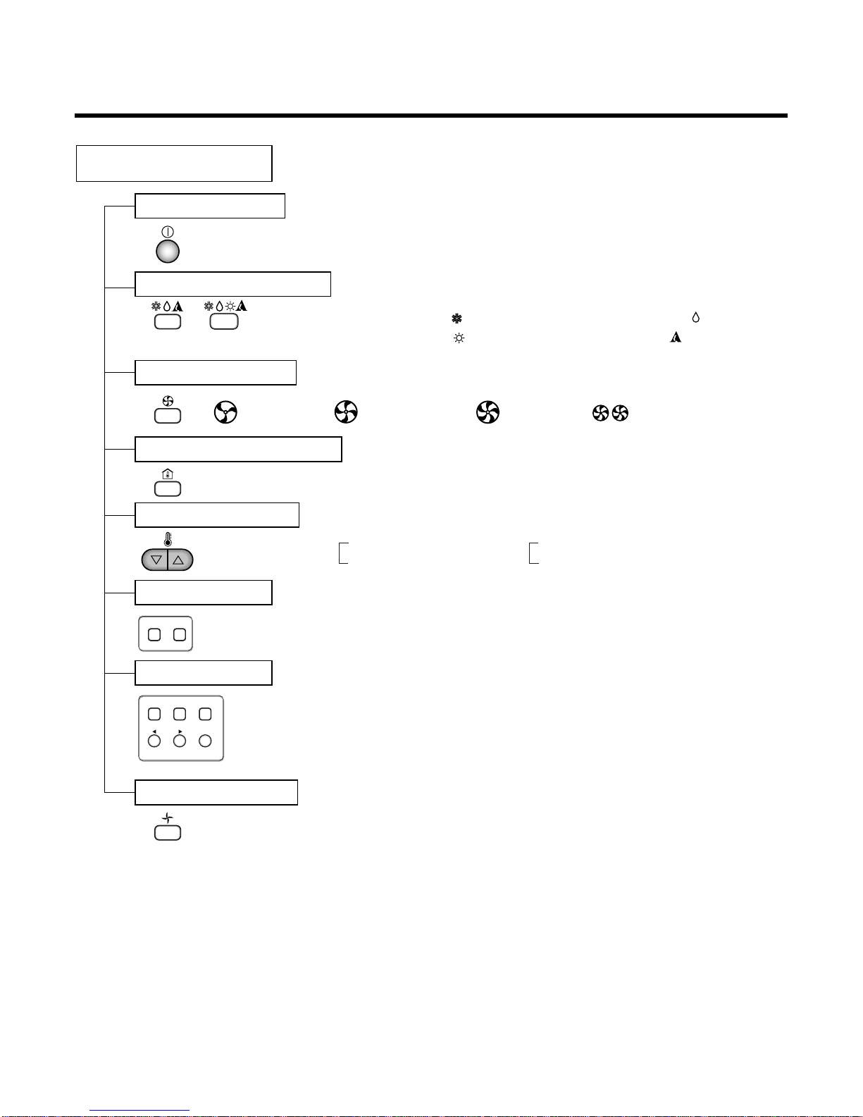
Remote Controller
Operation ON/OFF
Operation Mode Selection
Fan Speed Selection
Room Temperature Display
Temperature Setting
Setting the Timer
Weekly Program
(Cooling
model only)
(Heating
model only)
(Low) (Med) (High)
Cooling Operation Mode ( )
Heating Operation Mode ( ) Auto Operation Mode ( )
Soft Dry Operation Mode ( )
Fan Operation Mode
HI AUTOMEDLO
Program Holiday
SET/CLR
MinHour
Week
Timer CancelTimer Cancel
: High:39°C ↔ LOW:11°C
: Fan Operates without cooling & heating
Cooling Heating
Down to 18°C
Up to 30°C
Down to 16°C
Up to 30°C

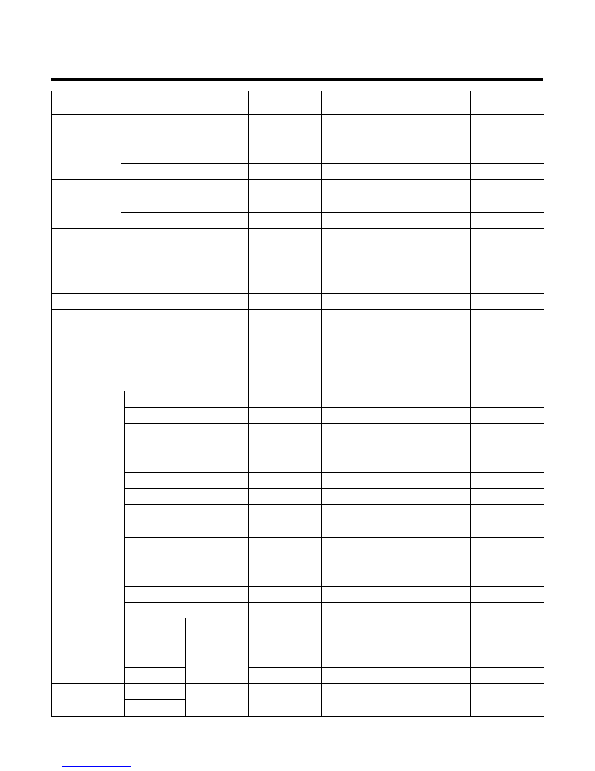
Product Specifications (Cooling & Heating)
–5–
Power Source Ø, V, Hz
Cooling Capacity kcal/h(BTU/h)
W
Input W
Heating Capacity kcal/h(BTU/h)
W
Input W
Rated Load Amp. Cooling A
Heating A
Air Volumn Cooling(H/M/L)
CMM(m
3
/min)
Heating(H/M/L)
Refrigerant(R-22) g
Drain Hose In. Dia mm
Main Cable
No. X mm
2
Connecting Cable
Remote Control Type
Refigerant Control Type
Fuction Soft Dry
Timer
Self Diagnosis
Deice Operation
Hot Start
Zone Control(Optional)
Central Control(Optional)
Group Control(Optional wiring)
Radio Frequency Control(Optional)
Weekly Programning
Thermistor
Drain Pump(Optional)
Auto changeover(Auto Operation: CL)
Stand-by Consumption 0
Connecting Pipe Liquid Inch
Gas (mm)
Dimension Indoor mm
Outdoor (W x H x D)
Net Indoor Kg
Weight
Outdoor
Model
LB-S3061BL LB-K3660BL LB-K4260BL LB-K4880BL
1, 220-240, 50 1, 220-240, 50 1, 220-240, 50 3, 380-415, 50
7,307(2,900) 9,072(36,000) 10,584(42,000) 12,096(48,000)
8,500 10,551 12,309 14,067
3,200 3,600 5,100 4,900
8,064(32,000) 9,072(36,000) 11,314(45,500) 12,096(48,000)
9,378 10,551 13,190 14,067
3,000 3,400 4,700 4,400
14 16 22.5 8
13.5 14 21 7.3
30/26/22 35/32/28 46/38/32 49/47/44
30/26/22 35/32/28 46/38/32 49/47/44
2,020 2,240 3,600 3,351
22.6 22.6 22.6 22.6
3*3.5 3*5.5 3*8.5 4*3.5
5*1.25 5*1.25 5*1.25 5*1.25
L.C.D Wired L.C.D Wired L.C.D Wired L.C.D Wired
Orifice/Capillary Orifice/Capillary Orifice/Capillary Orifice/Capillary
Ye s Ye s Ye s Ye s
24 Hours On/Off 24 Hours On/Off 24 Hours On/Off 24 Hours On/Off
Ye s Ye s Ye s Ye s
Ye s Ye s Ye s Ye s
Ye s Ye s Ye s Ye s
Optional Optional Optional Optional
Optional Optional Optional Optional
Ye s Ye s Ye s Ye s
Optional Optional Optional Optional
Ye s Ye s Ye s Ye s
Ye s Ye s Ye s Ye s
Optional Optional Optional Optional
Ye s Ye s Ye s Ye s
Ye s Ye s Ye s Ye s
3/8(9.52) 3/8(9.52) 3/8(9.52) 3/8(9.52)
5/8(15.88) 5/8(15.88) 3/4(19.05) 3/4(19.05)
890*350*560 1,030*350*435 1,030*350*435 1,030*350*435
870*800*320 870*800*320 900*1,220*370 900*1,220*370
32 37 37 40
72 72 90 92
–6–
3, 380-415, 50 3, 380-415, 50 3,380-415, 50 3, 380-415, 50
15,120(60,000) 18,143(72,000) 21,924(87,000) 25,200(100,000)
17,585 21,101 25,497 29,307
7,000 7,000 8,800 10,500
15,120(60,000) 18,143(72,000) 21,924(87,000) 26,208(104,000)
17,585 21,101 25,497 30,479
6,500 6,800 7,400 8,700
12.7 13.0 14.5 17.0
12.5 13.0 12.7 14.7
55/50/46 73/68/62 84/76/65 84/76/65
55/50/46 73/68/62 84/76/65 84/76/65
4,629 6,931 8,100 8,000
22.6 22.6 22.6 22.6
4*3.5 4*3.5 4*5.5 4*5.5
5*1.25 5*1.25 5*1.25 5*1.25
L.C.D Wired L.C.D Wired L.C.D Wired L.C.D Wired
Orifice/Capillary Orifice/Capillary Orifice/Capillary Orifice/Capillary
Ye s Ye s Ye s Ye s
24 Hours On/Off 24 Hours On/Off 24 Hours On/Off 24 Hours On/Off
Ye s Ye s Ye s Ye s
Ye s Ye s Ye s Ye s
Ye s Ye s Ye s Ye s
Optional Optional Optional Optional
Optional Optional Optional Optional
Ye s Ye s Ye s Ye s
Optional Optional Optional Optional
Ye s Ye s Ye s Ye s
Ye s Ye s Ye s Ye s
Optional Optional Optional Optional
Ye s Ye s Ye s Ye s
Ye s Ye s Ye s Ye s
3/8(9.52) 1/2(12.7) 5/8(15.88) 5/8(15.88)
3/4(19.05) 1(25.4) 9/8(28.0) 9/8(28.0)
1,120*400*575 1,420*400*575 1,596*450*658 1,596*450*658
900*1,220*370 1,245*930*650 1,245*930*650 1,245*930*650
51 58 84 88
92 185 190 195
Power Source Ø, V, Hz
Cooling Capacity kcal/h(BTU/h)
W
Input W
Heating Capacity kcal/h(BTU/h)
W
Input W
Rated Load Amp. Cooling A
Heating A
Air Volumn Cooling(H/M/L)
CMM(m
3
/min)
Heating(H/M/L)
Refrigerant(R-22) g
Drain Hose In. Dia mm
Main Cable
No. X mm
2
Connecting Cable
Remote Control Type
Refigerant Control Type
Fuction Soft Dry
Timer
Self Diagnosis
Deice Operation
Hot Start
Zone Control(Optional)
Central Control(Optional)
Group Control(Optional wiring)
Radio Frequency Control(Optional)
Weekly Programning
Thermistor
Drain Pump(Optional)
Auto changeover(Auto Operation: CL)
Stand-by Consumption 0
Connecting Pipe Liquid Inch
Gas (mm)
Dimension Indoor mm
Outdoor (W x H x D)
Net Indoor Kg
Weight
Outdoor
Model
LB-L6080BL LB-M7280BL LB-M9080BL LB-M1081BL
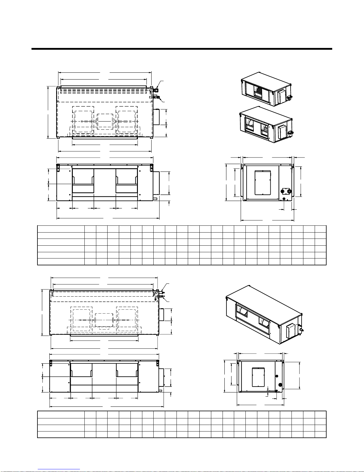
Dimensions
–7–
1. Indoor
"A" "B" "C" "D" "E" "F" "G" "J" "K" "L" "M" "N" "P" "Q" "R" "S" "T"
"V" "W" "X" "Y"
MODEL NO
LBNS3061BL
LBNK3661BL
LBNK4261BL
LBNK4881BL
LBNL6081BL
890
1040
1040
1040
1120
350
350
350
350
400
560
560
560
560
580
253
282
282
282
305
482
712
712
712
712
282
282
282
282
327
718
868
868
868
935
168
366
131
131
171
234
234
250
250
234
-
210
210
239
170
170
170
170
183
163
165
161
161
165
798
934
934
934
1014
798
937
937
937
1014
–
548
548
548
567
40
40
40
40
67
120
120
120
120
130
22
22
22
22
22
79
79
79
79
84
822
972
972
972
1052
514
514
514
514
533
"A" "B" "C" "D" "E" "F" "G" "J" "K" "L" "M" "N" "P" "Q" "R" "S" "T"
"V" "W" "X" "Y"
MODEL NO
LBNM7281BL
LBNM9081BL
LBNM1081BL
1415
1596
1596
400
450
450
580
658
658
303
303
303
833
835
835
327
377
377
1221
1403
1403
258
348
348
300
300
300
228
230
230
182
219
219
165
185
185
1327
1504
1504
1327
1504
1504
567
-
-
67
80
80
130
190
190
22
22
22
78
78
78
1351
1532
1532
533
612
612
"D"
"F"
"X"
"Y"
2323
LIQUID
LINE
SUCTION
LINE
"C"
"B"
"A"
"G"
"E"
169
"T"
"W"
"S"
250
"J" "K" "L" "K"
"Q"
"P"
"R"
"M"
"N"
"M"
"N"
"J" "K" "L" "K"
"X"
"A"
"S"
250
"P"
"E"
"Q"
"G"
"T"
169
"R"
LIQUID
LINE
SUCTION
LINE
"B"
"D"
23 23 "Y"
"C"
"F"
"V"
"W"
(30K/36K)
(42K/48K/60K)
(72K/90K/100K)
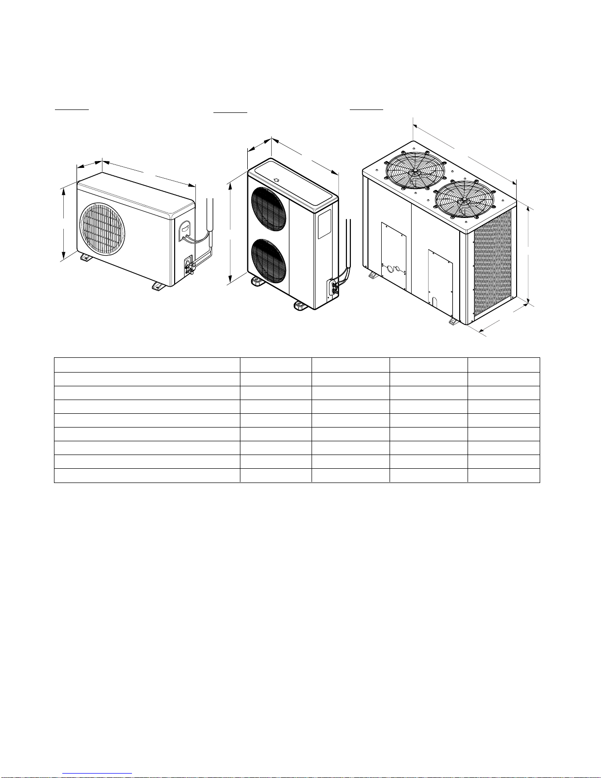
2. Outdoor Unit
–8–
Type: A
Type: B
T
ype: C
Model No. a b c TYPE
LBUS3061BL 870 320 800 A
LBUK3660BL 870 320 800 A
LBUK4260BL 900 370 1220 B
LBUK4880BL 900 370 1220 B
LBUL6080BL 900 370 1220 B
LBUM7280BL 1,245 650 930 C
LBUM9080BL 1,245 650 930 C
LBUM1081BL 1,245 650 930 C
(Unit: mm)
b
a
c
b
a
c
c
b
a
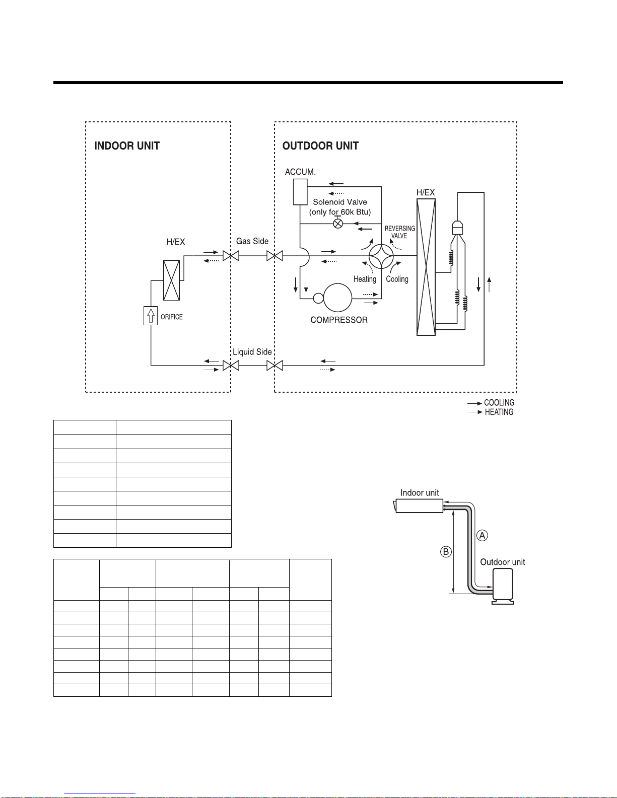
Refrigeration Cycle Diagram
–9–
Heat Pump
• If 60K Model is installed at a distance of 15m, 525g of refrigerant should be added
(15-7.5) x 70g = 525g
30K BTU/h
5/8" 3/8" 7.5 15 7.5 12.5 70
36K BTU/h
5/8" 3/8" 7.5 15 7.5 12.5 50
42K BTU/h 3/4'' 3/8" 7.5 15 7.5 12.5 70
48K BTU/h 3/4'' 3/8" 7.5 15 7.5 12.5 70
60K BTU/h 3/4'' 3/8" 7.5 15 7.5 12.5 70
72K BTU/h 1'' 1/2" 7.5 25 7.5 20 70
90K BTU/h 9/8'' 5/8" 7.5 30 7.5 20 90
100K BTU/h 9/8'' 5/8" 7.5 30 7.5 20 100
Capacity
Gas Liquid
Elevation B(m)
Piping Length
A(m)
* Additional
Refrigerant
(g/m)
Pipe Size (Diam-
eter: Ø)
inch
Standard
Standard
Max.
Max.
Capacity Orifice Number
30K 63
36K 62
42K 74
48K 86
60K 86
72K 98
90K 84
100K 104
Orifice Number
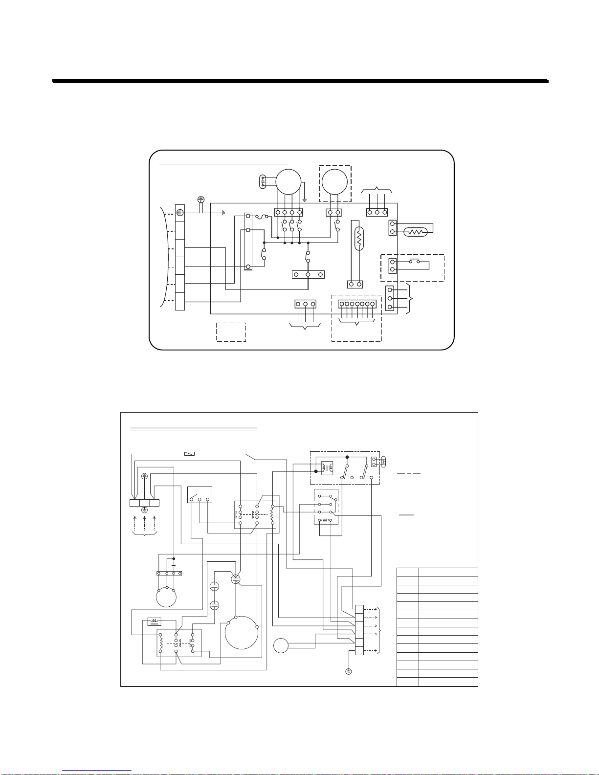
–10–
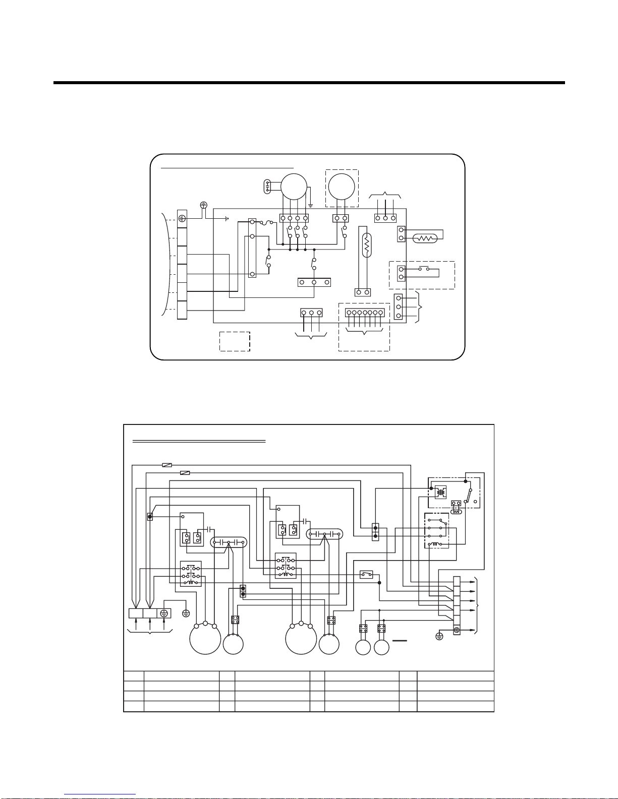
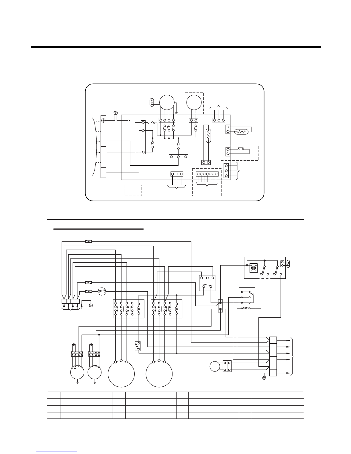
Wiring Diagram
Model : LB-S3061BL
1. Indoor(LBNS3061BL)
2. Outdoor(LBUS3061BL)
INDOOR WIRING DIAGRAM
INDOOR
MOTOR
DRAIN
PUMP
OR
OR
BR
BL
RD
BK
BLWHGY
BL
BL
BR
GN/YL
COMP
4 WAY
FUSE
250V10A
ROOM.
THERMISTOR
PIPE
THERMISTOR
RF REMOTE
CONTROL
FLOAT S/W
REMOTE
CONTROL
ZONE
CONTROL
OPTIONAL
EXTRA
TERMINAL
BLOCK
TO OUTDOOR UNIT
3854A20172T
3(L) 4(N) 5 6 7
TELE
CONTROL
GN/YLGN/YL
78
1
TM
240V 1Ø, 50Hz
POWER SUPPLY
BK
52C
Outdoor Unit Wiring Diagram
L1 L2
T1 T2
A2
A1
BK
WH
BK
52F1
12
34
56
WH
TIMER
BK
WH
YL
YL
BL
BL
WH
F1
BK
WH
WH
WH
C TH
20SV
52S,52C
Tmo
TM
52F1
Cr
CM
Co
FMo
F1
D.P
CH1
Cs
THERMISTOR FOR PIPE TEMP.
REVERSING COIL
MAGNECTIC CONTACTOR
TERMINAL BLOCK
MAIN TERMINAL BLOCK
RELAY FOR FMo
RUN CAPACITOR FOR CM
COMPRESSOR
RUN CAPACITOR FOR FMo
OUTDOOR FAN MOTOR
FUSE (250V, 5A)
DEICER PCB
CRANK CASE HEATER FOR CM
START CAPACITOR FOR CM
P/NO : 3854A20026V
20SV
WH
BK
RD
BL
BK
BK
WH
BK
BK
WIRING OF FIELD
(CONNECTING WIRE)
GN/YL
Tmo
To the indoor unit
WH
GN/YL
23
LN
1
2
3
4
5
6
BK
BK
BK
BK
YL
YL
YL
BK
RD
WH
RD
RD
OR
R
C
S
CM
Cr
FMo
BK
BK
BKBK
WH
52S
REACTOR
A2A1T3L3T2
L2
NOTE
BL : BLUE
BK : BLACK
BR : BROWN
RD : RED
WH : WHITE
YL : YELLOW
OR : ORANGE
GN/YL : GREEN/YELLOW
TNS
NC NO NC NO
C TH
D.P
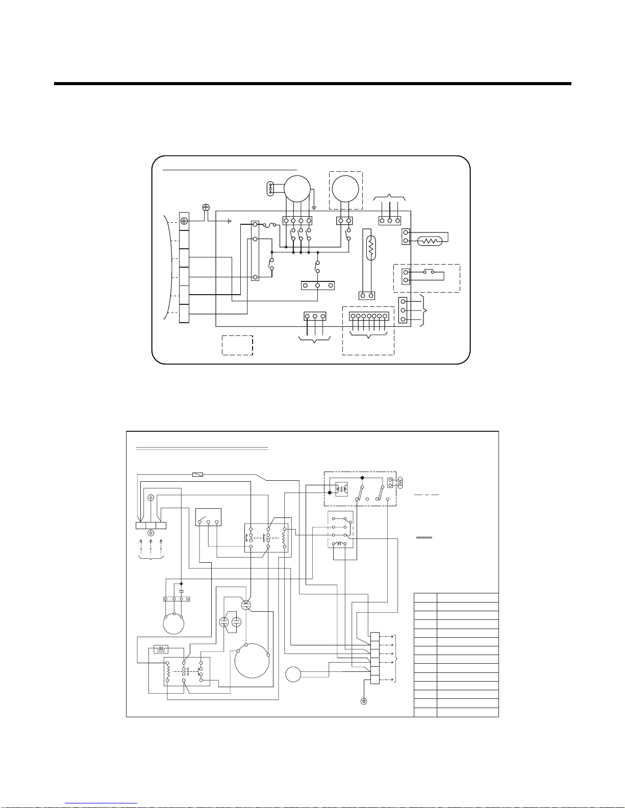
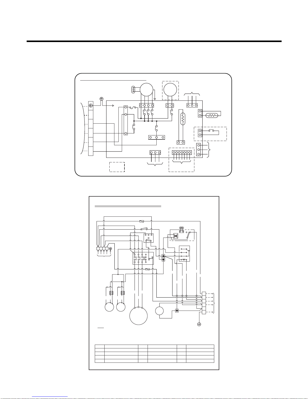
–11–
Model : LB-K3660BL
1. Indoor (LBNK3661BL)
2. Outdoor (LBUK3660BL)
78
1
TM
240V 1Ø, 50Hz
POWER SUPPLY
BK
52C
Outdoor Unit Wiring Diagram
L1 L2
T1 T2
A2
A1
BK
WH
BK
52F1
12
34
56
WH
TIMER
BK
WH
YL
YL
BL
BL
WH
F1
BK
WH
WH
WH
C TH
20SV
52S,52C
Tmo
TM
52F1
Cr
CM
Co
FMo
F1
D.P
CH1
Cs
THERMISTOR FOR PIPE TEMP.
REVERSING COIL
MAGNECTIC CONTACTOR
TERMINAL BLOCK
MAIN TERMINAL BLOCK
RELAY FOR FMo
RUN CAPACITOR FOR CM
COMPRESSOR
RUN CAPACITOR FOR FMo
OUTDOOR FAN MOTOR
FUSE (250V, 5A)
DEICER PCB
CRANK CASE HEATER FOR CM
START CAPACITOR FOR CM
P/NO : 3854A20026W
20SV
WH
BK
RD
BL
BK
BK
WH
BK
BK
WIRING OF FIELD
(CONNECTING WIRE)
GN/YL
Tmo
To the indoor unit
WH
GN/YL
23
LN
1
2
3
4
5
6
BK
BK
BK
BK
YL
BK
YL
YL
BK
RD
WH
RD
RD
OR
R
C
S
CM
Cr
Cs
FMo
BK
BK
BKBK
WH
52S
REACTOR
A2A1T3L3T2
L2
NOTE
BL : BLUE
BK : BLACK
BR : BROWN
RD : RED
WH : WHITE
YL : YELLOW
OR : ORANGE
GN/YL : GREEN/YELLOW
TNS
NC NO NC NO
C TH
D.P
INDOOR WIRING DIAGRAM
INDOOR
MOTOR
DRAIN
PUMP
OR
OR
BR
BL
RD
BK
BLWHGY
BL
BL
BR
GN/YL
COMP
4 WAY
FUSE
250V10A
ROOM.
THERMISTOR
PIPE
THERMISTOR
RF REMOTE
CONTROL
FLOAT S/W
REMOTE
CONTROL
ZONE
CONTROL
OPTIONAL
EXTRA
TERMINAL
BLOCK
TO OUTDOOR UNIT
3854A20172T
3(L) 4(N) 5 6 7
TELE
CONTROL
GN/YLGN/YL
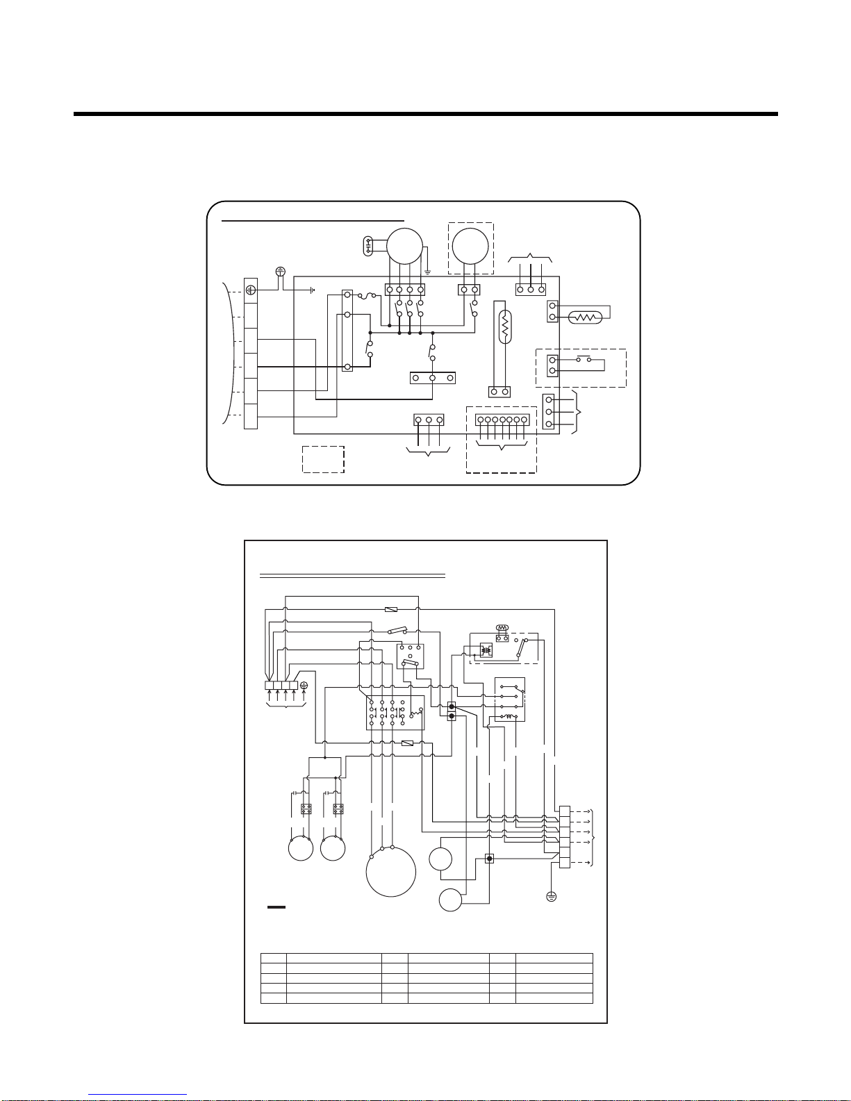
–12–
Model : LB-K4260BL
1. Indoor (LBNK4261BL)
2. Outdoor (LBUK4260BL)
OUTDOOR UNIT WIRING DIAGRAM
P/No.:3854A20135J
F1
S.S(A)
S.S(B)
52C(A)
52C(B)
52F1
D.P
TNS
COMP
49C
R
S
Tm
1(L)
F1,2
49C
FMo
49FMo
FUSE(250V,5A)
INTERNAL O.L.P FOR COMP.
OUTDOOR FAN MOTOR
INTERNAL T.P FOR FMo
DEICER PCB.
THERMISTOR FOR PIPE TEMP.(OUTDOOR)
4-WAY VALVE COIL
START CAPACITOR FOR FMo
RELAY FOR COMP
RELAY FOR FMo
SOFT START PCB.
RUN CAPACITOR FOR FMo
MAIN TERMINAL BLOCK
TERMINAL BLOCK FOR CONNECTING
3 PHASE DETECTOR
5 SEC. DELAY TIMER
D.P
C TH
20SV
Cs
52C
52F1
S.S
Cr
Tm
Tmo
3.P.D
T.D
2(N)
C
COMP
49C
R
S
C
POWER SUPPLY
1Ø,230V,50Hz~
FMo
49FMo
FMo
49FMo
20SV 20SV
NOTE
TO INDOOR UNIT
CHF
Cs(A)
Cr(A)
Cr(B)
T.D
Tmo
F2
BK
BL
BK
NC NO
CTH
BK
RD
RD
BK
WH
WH
BK
BL : BLUE
BK : BLACK
BR : BROWN
OR : ORANGE
RD : RED
WH : WHITE
YL : YELLOW
GN/YL : GREEN/YELLOW
BR
BR
BL
BL
BRRDBK
BL
BK
OR
BK
OR
YL
BK
BKBKBK
BK
1(L) 2(N) 3 4 5
OR OR
YL
YL
YL
RD
RD
BK
CHF
WH
BKBKBK
WH
WH
WH
WH
WH
WH
WH
WHWHWH
WH
YL
YL
TB3
TB5
TB1
TB2
TB6
CN-Power
CN-Power
RYComp
434
4
132
56
78
3
434
3
RYS/Cap
Cs(B)
RYComp
RYS/Cap
INDOOR WIRING DIAGRAM
INDOOR
MOTOR
DRAIN
PUMP
OR
OR
BR
BL
RD
BK
BLWHGY
BL
BL
BR
GN/YL
COMP
4 WAY
FUSE
250V10A
ROOM.
THERMISTOR
PIPE
THERMISTOR
RF REMOTE
CONTROL
FLOAT S/W
REMOTE
CONTROL
ZONE
CONTROL
OPTIONAL
EXTRA
TERMINAL
BLOCK
TO OUTDOOR UNIT
3854A20172T
3(L) 4(N) 5 6 7
TELE
CONTROL
GN/YLGN/YL
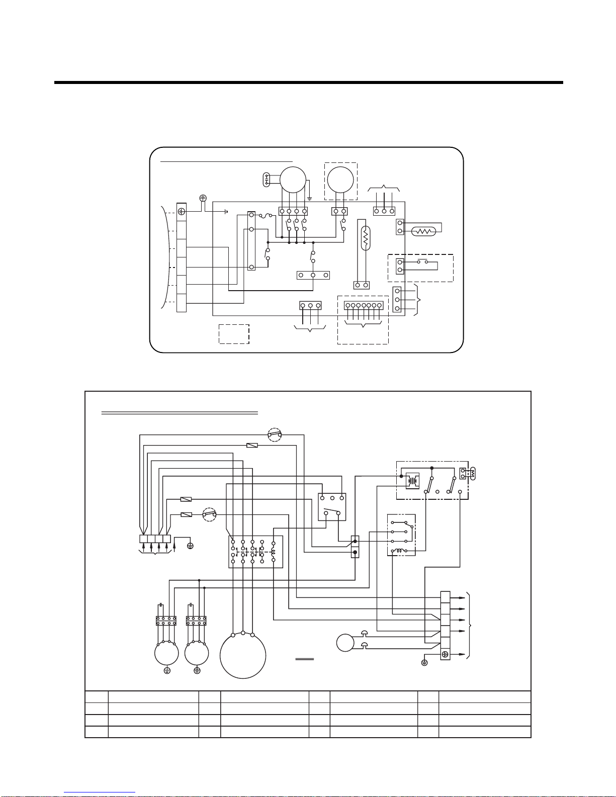
–13–
Model : LB-K4880BL
1. Indoor (LBNK4881BL)
2. Outdoor (LBUK4880BL)
INDOOR WIRING DIAGRAM
INDOOR
MOTOR
DRAIN
PUMP
OR
OR
BR
BL
RD
BK
BLWHGY
BL
BL
BR
GN/YL
COMP
4 WAY
FUSE
250V10A
ROOM.
THERMISTOR
PIPE
THERMISTOR
RF REMOTE
CONTROL
FLOAT S/W
REMOTE
CONTROL
ZONE
CONTROL
OPTIONAL
EXTRA
TERMINAL
BLOCK
TO OUTDOOR UNIT
3854A20172T
3(L) 4(N) 5 6 7
TELE
CONTROL
GN/YLGN/YL
NOTE
BL : BLUE
BK : BLACK
OR : ORANGE
GN/YL : GREEN/YELLOW
RD : RED
WH : WHITE
YL : YELLOW
Outdoor Unit Wiring Diagram
RTM
3Ø,380-415V, 50Hz
POWER SUPPLY
STN
BK
BK
BK
BK
RD
WH
WH
RD
OR
BK
63H2
3.D.P
WH
WH
YL
D.P
CTH
TNS
NO
NC
WH
OR
BK
52F1
52C
12345631
T/B1
T/B2
T/B3
32
B
A
FMo
49FMo
FMo
49FMo
YL BK
OR
BK RD
WH
CM
12
34
56
78
YL BK
OR
BK
BK
BL
BL
BL
BL
WH
WH
Co Co
20SV
GN/YL
TMo
To the indoor unit
1
2
3
4
5
6
BK
WHWH
YL
RD
F1
BK
63H2
C TH
49FMo
20SV
CM
HIGH PRESSURE SWITCH FOR HEATING
THERMISTOR FOR PIPE TEMP.
INTERNAL T.P FOR FMo
REVERSING COIL
COMPRESSOR
52C
TM
52F1
D.P
3.D.P
MAGNECTIC CONTACTOR
MAIN TERMINAL BLOCK
RELAY FOR FMo
DEICER PCB
3 PHASE DETECTOR
Co
FMo
F1
TMo
SOL
RUN CAPACITOR FOR FMo
OUTDOOR FAN MOTOR
FUSE (250V,10A)
TERMINAL BLOCK
SOLENOID VALVE
P/NO : 3854A20021Z
F1
RABST
VUW
–14–
Model : LB-L6080BL
1. Indoor (LBNL6081BL)
2. Outdoor (LBUL6080BL)
INDOOR WIRING DIAGRAM
INDOOR
MOTOR
DRAIN
PUMP
OR
OR
BR
BL
RD
BK
BLWHGY
BL
BL
BR
GN/YL
COMP
4 WAY
FUSE
250V10A
ROOM.
THERMISTOR
PIPE
THERMISTOR
RF REMOTE
CONTROL
FLOAT S/W
REMOTE
CONTROL
ZONE
CONTROL
OPTIONAL
EXTRA
TERMINAL
BLOCK
TO OUTDOOR UNIT
3854A20172T
3(L) 4(N) 5 6 7
TELE
CONTROL
GN/YLGN/YL
NOTE
BL : BLUE
BK : BLACK
OR : ORANGE
GN/YL : GREEN/YELLOW
RD : RED
WH : WHITE
YL : YELLOW
Outdoor Unit Wiring Diagram
RTM
3Ø,380-415V, 50Hz
POWER SUPPLY
STN
BK
BK
BK
BK
RD
WH
WH
RD
OR
BK
63H2
WH
WH
YL
D.P
CTH
TNS
NO
NC
WH
OR
BK
52F1
52C
12345631
T/B1
T/B2
T/B3
32
B
A
FMo
49FMo
FMo
49FMo
YL BK
OR
BK
T3
T2
T1
RD
WH
CM
12
34
56
78
YL BK
OR
BK
BK
BL
BL
BL
BL
WH
WH
Co Co
20SV
SOL
GN/YL
TMo
To the indoor unit
1
2
3
4
5
6
BK
WHWH
YL
RD
F1
BK
63H2
C TH
49FMo
20SV
CM
HIGH PRESSURE SWITCH FOR HEATING
THERMISTOR FOR PIPE TEMP.
INTERNAL T.P FOR FMo
REVERSING COIL
COMPRESSOR
52C
TM
52F1
D.P
3.D.P
MAGNECTIC CONTACTOR
MAIN TERMINAL BLOCK
RELAY FOR FMo
DEICER PCB
3 PHASE DETECTOR
Co
FMo
F1
TMo
SOL
RUN CAPACITOR FOR FMo
OUTDOOR FAN MOTOR
FUSE (250V,10A)
TERMINAL BLOCK
SOLENOID VALVE
P/NO : 3854A20021W
F1
RABST
–15–
Model : LB-M7280BL
1. Indoor (LBNM7281BL)
2. Outdoor (LBUM7280BL)
OUTDOOR UNIT WIRING DIAGRAM
P/NO.:3854A20021V
BK
F1
BK
BK
TNS
NC NO NC NO
C TH
BK
BK
BK
12
34
56
78
R
BA
ST
BK
WH
WH
WH WH
WH
WH
F2
RD
RD
RD
BK
GN/YL
1(L)
2(N)
3
4
5
Tmo
TO INDOOR UNIT
YL
OR
YL
BL
BK
BL
BL
BL : BLUE
BK : BLACK
BR : BROWN
OR : ORANGE
F1,2,3
49C
FMo
49FMo
Co
D.P
C TH
20SV
52C
52F1
TM
TMo
63H1
63H2
3.P.D
HIGH PRESSURE SWITCH
HIGH PRESSURE SWITCH FOR HEATING
3 PHASE DETECTOR
MAGNETIC CONTACTOR
RELAY FOR FMo
MAIN TERMINAL BLOCK
TERMINAL BLOCK FOR CONNECTING
RUN CAPACITOR FOR FMo
DEICER PCB
THETMISTOR FOR PIPE TEMP.(OUTDOOR)
4-WAY VALVE COIL
FUSE(250V,10A)
INTERNAL O.L.P FOR COMP.
OUTDOOR FAN MOTOR
INTERNAL T.P FOR FMo
RD : RED
WH : WHITE
YL : YELLOW
GN/YL : GREEN/YELLOW
20SV
NOTE
YLBROR
BK
YLBROR
BK
YLBROR
BK
YLBROR
BK
RD
13521
24622
A1
A2
RDBKWH
GN/YL
F3
Tm
Co
FMo
49FMo
FMo
49FMo
COMP
49C
Co
T1
T3
T2
POWER SUPPLY
3Ø,380-415,50Hz
TERMINAL(4P)
RSTN
63H1
63H2
52C
52F1
3.P.D
D.P
RD
INDOOR WIRING DIAGRAM
INDOOR
MOTOR
DRAIN
PUMP
OR
OR
BR
BL
RD
BK
BLWHGY
BL
BL
BR
GN/YL
COMP
4 WAY
FUSE
250V10A
ROOM.
THERMISTOR
PIPE
THERMISTOR
RF REMOTE
CONTROL
FLOAT S/W
REMOTE
CONTROL
ZONE
CONTROL
OPTIONAL
EXTRA
TERMINAL
BLOCK
TO OUTDOOR UNIT
3854A20172T
3(L) 4(N) 5 6 7
TELE
CONTROL
GN/YLGN/YL
–16–
Model : LB-M9080BL/LB-M1081BL
1. Indoor (LBNM9081BL/LBNM1081BL)
2. Outdoor (LBUM9080BL/LBUM1081BL)
3854A20317B
OUTDOOR UNIT WIRING DIAGRAM
BR
BK
BK
BK
BK
TNS
NC NO NC NO
C TH
D.P
WH
YL
BL
BL
BL
BL
RD
20SV
BR
BR
TO INDOOR UNIT
BR
1(L)
2(N)
3
4
5
6
BL
BK
GN/YL
RD
BL
12
34
56
78
TB1
TB2
52F1
3.P.D
RST
AB
WH
WH
RD
RD
F2
63H1
F3
BL BL
BL
YLYL
BRBR
BKBK
OROR
YLYL
BRBR
BK
BK
BR
BL
RD
YL
WH
RD
BK
OROR
R
POWER SUPPLY
3Ø,380-415,50Hz
TERMINAL(4P)
Tm
Tmo
Co
FMo
49FMo
F1,F2,F3
49C
FMo
49FMo
FUSE(250V,10A)
INTERNAL O.L.P FOR COMP.
OUTDOOR FAN MOTOR
INTERNAL T.P FOR FMo
52C
52F1
TM
TMo
MAGNETIC CONTACTOR
RELAY FOR FMo
MAIN TERMINAL BLOCK
TERMINAL BLOCK FOR CONNECTING
63H1
63H2
3.P.D
T. D
HIGH PRESSURE SWITCH
HIGH PRESSURE SWITCH FOR HEATING
3 PHASE DETECTOR
5 SEC. DELAY TIMER
Co
D.P
C TH
20SV
RUN CAPACITOR FOR FMo
DEICER PCB
THERMISTOR FOR PIPE TEMP.(OUTDOOR)
REVERSING COIL
FMo
49FMo
A-COMP
49C
B-COMP
49C
Co
V
U
W
V
U
W
BKWHRD
STN
BL
GN/YL
A-52C
A2
21
22
12345
6
A1
A2
21
22
A1
B-52C
12345
6
T.D
RD
F1
INDOOR WIRING DIAGRAM
INDOOR
MOTOR
DRAIN
PUMP
OR
OR
BR
BL
RD
BK
BLWHGY
BL
BL
BR
GN/YL
COMP
4 WAY
FUSE
250V10A
ROOM.
THERMISTOR
PIPE
THERMISTOR
RF REMOTE
CONTROL
FLOAT S/W
REMOTE
CONTROL
ZONE
CONTROL
OPTIONAL
EXTRA
TERMINAL
BLOCK
TO OUTDOOR UNIT
3854A20172T
3(L) 4(N) 5 6 7
TELE
CONTROL
GN/YLGN/YL
–17–
Operation Details
(1) The function of main control
1. Time Delay safety Control
• 3min
...
The compressor is ceased for 3minutes to balance the pressure in the refrigeration cycle.
(Protection of compressor)
• 30sec
...
The 4-way valve is ceased for 30sec. to prevent the refrigerant-gas abnormal noise when the Heating
operation is OFF or switched to the other operation mode while compress is off.
While compressor is running, it takes 3~5 seconds to switch.
2. Soft-Dry Operation
• The indoor fan speed is automatically set to the low, so the shift of the indoor fan speed is impossible because of
already being set to the best speed for Dry Operation by Micom Control.
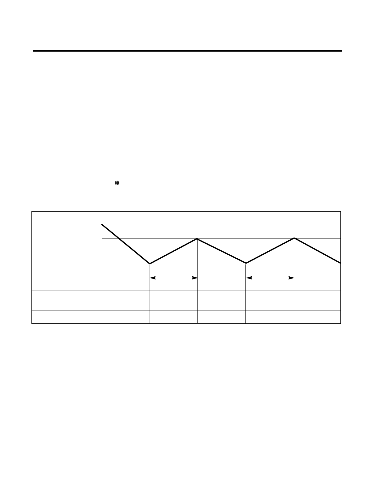
3. Cooling Mode Operation
• When selecting the Cooling( ) Mode Operation, the unit will operate according to the setting by the remote controller and the operation diagram is as following.
Intake Air temp.
SET TEMP.+0.5°C
(COMP. ON)
SET TEMP. -0.5°C
(COMP. OFF) More than More than
3 minutes 3 minutes
Selecting Selecting Selecting
fan speed fan speed fan speed
COMPRESSOR ON OFF ON OFF ON
INDOOR FAN Low Low
–18–
Intake Air temp.
Setting temp.+3°C
(Compressor OFF)
Setting temp.
(Compressor ON)
INDOOR FAN Low OFF Low Low OFF
COMPRESSOR ON OFF ON OFF
• A point; While the indoor Heat-Exchanger temperature is higher than 40°C fan operates at low speed, when
it becomes lower than 40˚C fan stops.
• B point; When the indoor Heat-Exchanger temperature is higher than 42°C, fan operates at seleted fan
speed, when it becomes lower than 39°C, the fan operates at low speed.
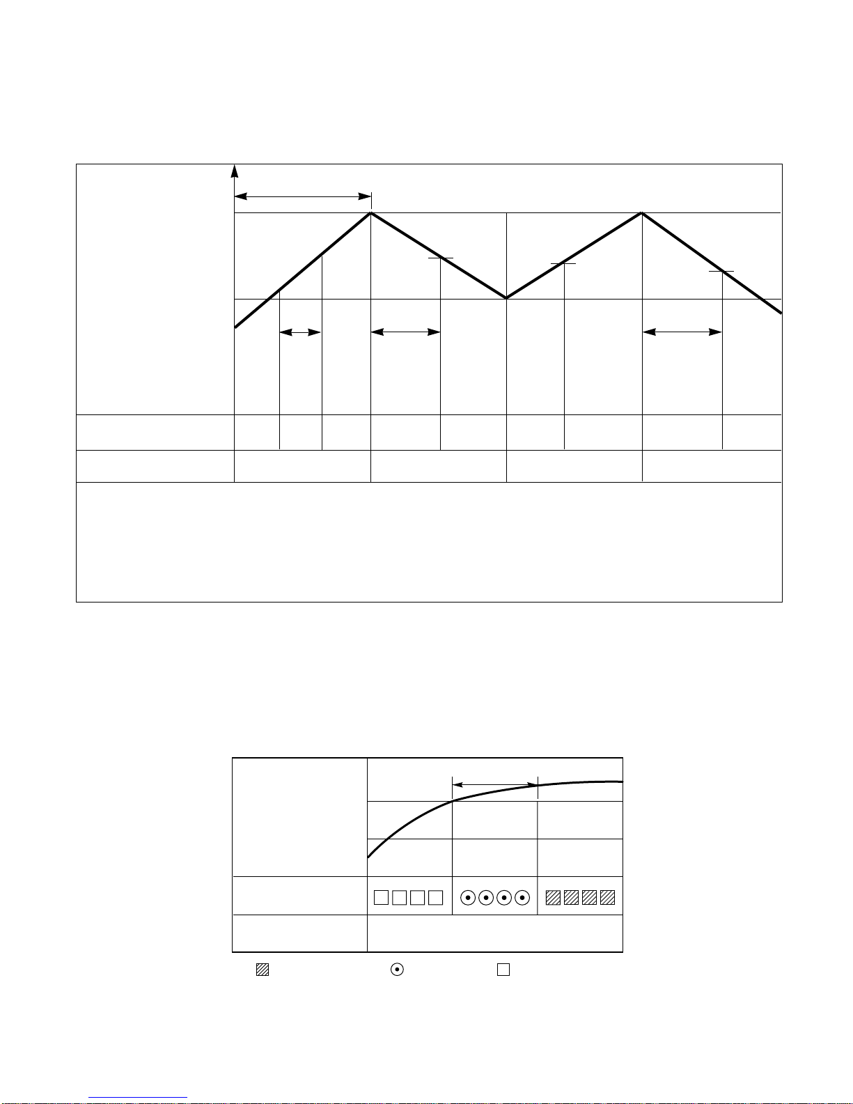
4. Heating Mode Operation (Except Cooling Model)
The unit will operate according to the setting by the remote controller and the operation diagram is shown as following.
Hot Start
Low
Selecting
Fan Speed
minimum 3min
Selecting fan
speed
minimum
10sec.
1min
AA
minimum
10sec.
B
5. Hot-Start Control
• The indoor fan stops until the evaporator piping temperature will be reached to 31°C.
• The operation diagram is as following.
PIPING
TEMPERATURE
1min
COMPRESSOR
INDOOR FAN
ON
28°C
: Selected Fan : Low Fan : Fan Stop
31°C
–19–
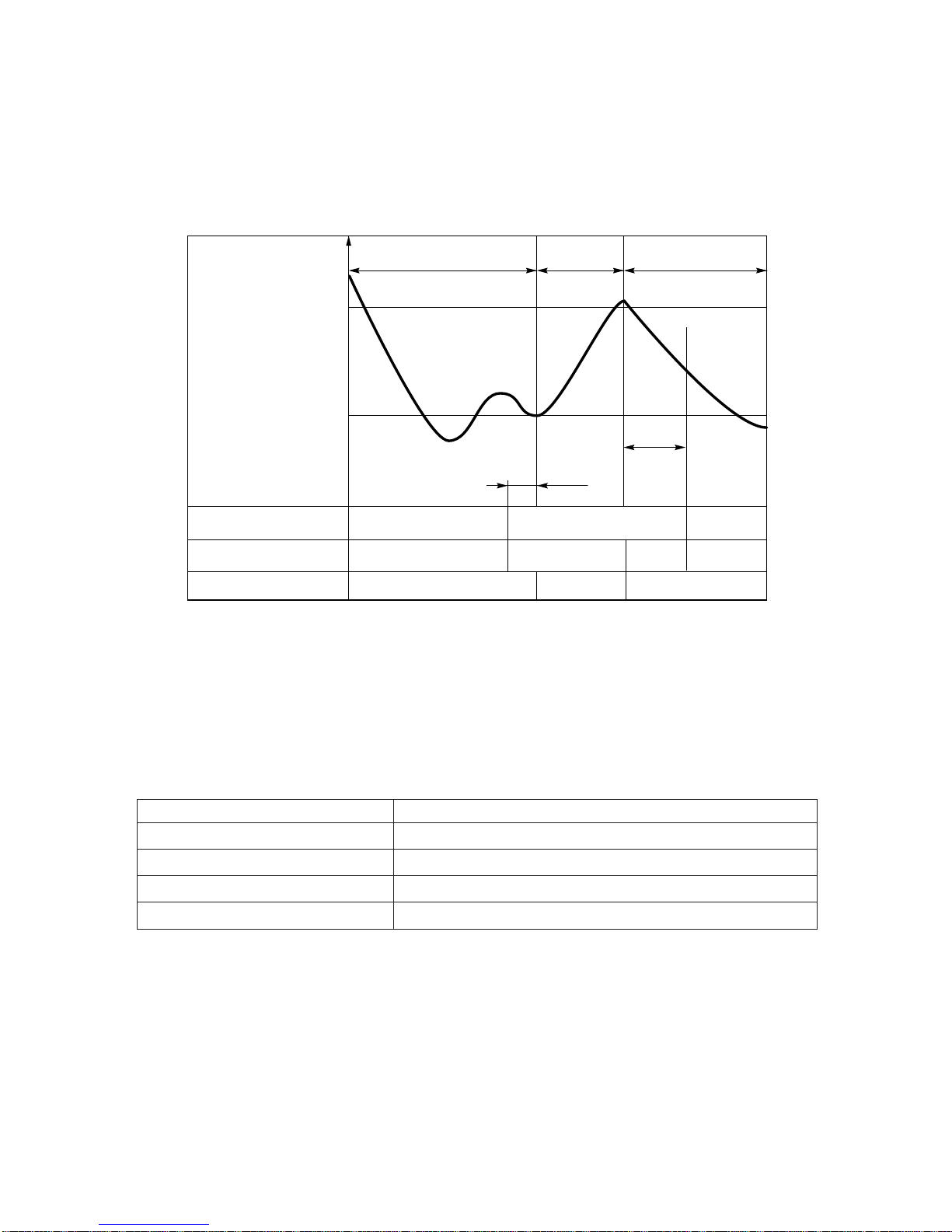
6. Defrost Control
• Defrost control is availavle 45 minutes later since heating mode operation started, and it will not prolong over
10 minutes.
• Defrost control is carried out when the outdoor pipe temp. falls below -6°C for more than 3 minutes after 45
minutes passed from starting of heating operation.
• Defrost ends after 10 minutes passed from starting of defrost operation or when the outdoor pipe temp. rises
over 12°C after 5 minutes passed from starting of defrost.
7. Self-diagnosis Function
• 'CHECK' will flash in the remote controller display when a problem occurs. Then please contact your dealer.
• Correct the accident point as shown in the table below before restarting operation.
• During the normal operation 'CHECK' won't be displayed in the remote controller.
Remote controller LCD Accident Point
CH 01 Indoor room temperature thermistor error
CH 02 Indoor piping thermistor error
CH 03
Indoor main body / Remote controller unit communication error
CH 04(Optional) Water level float switch error
More than 45 minutes
of heating operation
Within
9min. 45sec.
ON OFF
ON ON
ON
ON OFF
OFF
COMPRESSOR
4-WAY VALVE
INDOOR FAN
-6°C ON
12°C OFF
The outdoor
piping Temp.
ON
More than 10 min.
running of compressor
More than 45 minutes
of heating operation
5sec.
HOT-
START
ON
–20–
Installation of Indoor, Outdoor Unit
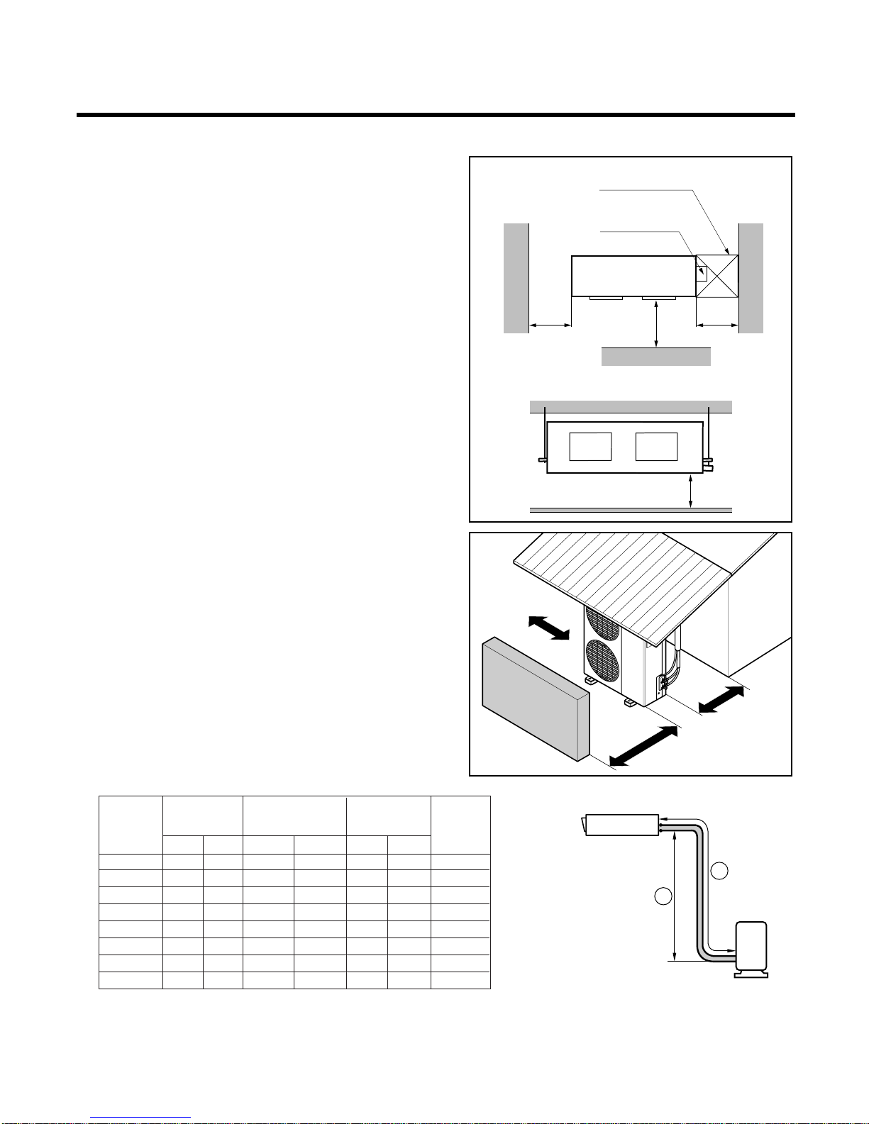
1. Selection of the best location
1) Indoor unit
Select location
Install the air conditioner in the location that satisfies the following conditions.
• The place shall easily bear a load exceeding four
times the indoor unit’s weight.
• The place shall be able to inspect the unit as the
figure.
• The place where the unit shall be leveled.
• The place shall allow easy water drainage.(Suit-
able dimension “H” is necessary to get a slope to
drain as figure.)
• The place shall easily connect with the outdoor
unit.
• The place where the unit is not affected by an
electrical noise.
• The place where air circulation in the room will be
good .
• There should not be any heat source or steam
near the unit.
2) Outdoor unit
• If an awning is built over the unit to prevent direct
sunlight or rain exposure, be careful that heat
radiation from the condenser is not restricted.
• There should not be any animals or plants which
could be affected by hot air discharged.
• Ensure the spaces indicated by arrows from the
wall, ceiling, fence or other obstacles.
3) Piping length and the elevation
Indoor unit
Outdoor unit
B
A
More than
30cm
More than
30cm
More than
70cm
Sunroof
Fence or
obstacles
Top view
(unit: mm)
H
Front view
600600
Front
Inspection hole
(600X600)
Control box
1000
30K BTU/h
5/8" 3/8" 7.5 15 7.5 12.5 70
36K BTU/h
5/8" 3/8" 7.5 15 7.5 12.5 50
42K BTU/h 3/4'' 3/8" 7.5 15 7.5 12.5 70
48K BTU/h 3/4'' 3/8" 7.5 15 7.5 12.5 70
60K BTU/h 3/4'' 3/8" 7.5 15 7.5 12.5 70
72K BTU/h 1'' 1/2" 7.5 25 7.5 20 70
90K BTU/h 9/8'' 5/8" 7.5 30 7.5 20 90
100K BTU/h 9/8'' 5/8" 7.5 30 7.5 20 100
Capacity
Gas Liquid
Elevation B(m)
Piping Length
A(m)
* Additional
Refrigerant
(g/m)
Pipe Size (Diam-
eter: Ø)
inch
Standard
Standard
Max.
Max.
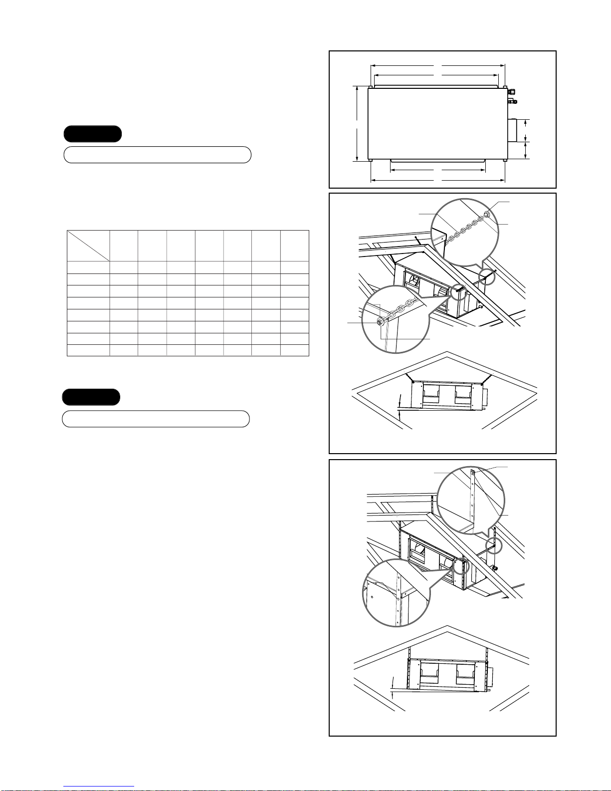
2. Ceiling dimension and hanging
bolt location
■ Installation of Unit
Install the unit above the ceiling correctly.
• Apply a joint-canvas between the unit and duct to
absorb unnecessary vibration.
• Apply a filter Accessory at air return hole.
• Install the unit leaning to a drainage hole side as a
figure for easy water drainage.
• A place where the unit will be leveled and that can
support the weight of the unit.
• A place where the unit can withstand its vibration.
• A place where service can be easily performed.
–21–
CASE 1
POSITION OF SUSPENSION BOLT
CASE 2
POSITION OF CONSOLE BOLT
(Unit:mm)
Q
G
R
169
T
E
P
Flat washer
(Zinc plated)
3mm steel chain
1/4" coach
screw
(Self-tapping
wood screw
with hexagonal
head)
Flat washer
(Zinc plated)
Flat washer
(Zinc plated)
Flat washer
(Zinc plated)
2˚
2˚
M6
(Zinc plated)
screw & Nut
M6
(Zinc plated)
screw & Nut
Galvanized steel
(Pre-punched) strap
1/4" coach
screw
(Self-tapping
wood screw
with hexagonal
head)
Flat washer
(Zinc plated)
Self-tapping
screw or M6
(Zinc plated)
screw & Nut
Self-tapping
screw or M6
(Zinc plated)
screw & Nut
TYPE-A (Using steel chain)
TYPE-B (Using Galvanized steel strap)
NOTE:
• Throughly study the following installation locations:
1. In such places as restaurants and kitchens, considerable
amount of oil steam and flour adhere to the fan, the fin of the
heat exchanger, resulting in heat exchange reduction, spraying,
dispersing of water drops, etc.
In these cases, take the following actions:
• Make sure that the ventilation fan for smoke-collecting hood on
a cooking table has sufficient capacity so that it draws oily
steam which should not flow into the suction of the air conditioner.
• Make enough distance from a cooking room to install the air
conditioner in such a place where it may not suck in oil steam.
2. Avoid installing air conditioner in such circumstances where
cutting oil mist or iron powder is in suspension in factories, etc.
3. Avoid places where inflammable gas is generated, flows in, is
stored or vented.
4. Avoid places where sulfurous acid gas or corrosive gas is
generated.
5. Avoid places near high frequency generators.
EFGPQRT
Dimension
Model No.
LBNS3061BL 482 282 718 798 798 - 120
LBNK3661BL 712 284 868 934 937 548 120
LBNK4261BL 712 282 868 934 937 548 120
LBNK4881BL 712 282 868 934 937 548 120
LBNL6081BL 712 327 935 1014 1014 567 130
LBNM7281BL 833 327 1221 1313 1313 567 130
LBNM9081BL 835 377 1403 1504 1504 - 190
LBNM1081BL 835 377 1403 1504 1504 - 190
 Loading...