

LG GC-B379SQA, GC-B379SCA, GC-B409SQA, GC-B409SCA, lbn10551 Series Service Manual
...
3SECS.
FREEZERFREEZER
EXPRESS FRZ.
ECO MODE
FRIDGE
CHILD LOCK
DOOR ALARM
Ref.No
GC-B379S*QA
GC-B409S*QA
Ref.No
GC-B379S*CA
GC-B409S*CA
REFRIGERATOR
SERVICE MANUAL
http://biz.lgservice.com
MODEL/COLOR:

SAFETY PRECAUTIONS ............................................................................................................................................................................................. 3
SERVICING PRECAUTIONS ....................................................................................................................................................................................... 4
SPECIFICATIONS .......................................................................................................................................................................................................... 5
PARTS IDENTIFICATION ............................................................................................................................................................................................ 6
INSTRUCTIONS FOR REVERSING DOOR SWING ............................................................................................................................................. 7-8
DISASSEMBLY ............................................................................................................................................................................................................... 8
DOOR ........................................................................................................................................................................................................................... 8
DOOR SWITCH .......................................................................................................................................................................................................... 8
REFRIGERATOR ROOM LAMP ............................................................................................................................................................................. 9
FAN AND FAN MOTOR …………………………………………………………………………………………………………...….............................................................. 9
DEFROST CONTROL ASSEMBLY ………………………………………………………………………………………………............................................................ 9
HEATER, SHEATH ……………………………………………………………………………………………………………………................................................................. 9
DISPLAY REMOVE ................................................................................................................................................................................................... 10
ADJUSTMENT .............................................................................................................................................................................................................. 10
COMPRESSOR ......................................................................................................................................................................................................... 10
PTC-STARTER ......................................................................................................................................................................................................... 10-11
NOTE TO USE PTC-STARTER ............................................................................................................................................................................ 11
OLP (OVER LOAD PROTECTOR) ....................................................................................................................................................................... 11
CIRCUIT DIAGRAM ..................................................................................................................................................................................................... 12
TROUBLESHOOTING ................................................................................................................................................................................................. 13
COMPRESSOR AND ELECTRIC COMPONENTS ......................................................................................................................................... 13
RELAY ASSEMBLY (PTC AND OLP) ................................................................................................................................................................. 14
ANOTHER ELECTRIC COMPONENT ................................................................................................................................................................ 15
SERVICE DIAGNOSIS CHART …………………………………………………………………………………………………............................................................. 16
REFRIGERATING CYCLE ...................................................................................................................................................................................... 17-19
MICOM FUNCTION & PCB CIRCUIT EXPLANATION ..................................................................................................................................... 20-34
EXPLODED VIEW .......................................................................................................................................................................................................... 35-38
Contents
APPENDIX FOR REFRIGERATORS SERVICE MAINTENANCE MANUAL ................................................................................................. 39
CONTENTS
2

Please read the following instructions before servicing your refrigerator.
1. Check the set for electric losses.
2. Unplug prior to servicing to prevent electric shock.
3. Whenever testing with power on, wear rubber gloves to prevent electric shock.
4. If you use any kind of appliance, check regular current, voltage and capacity.
5. Don't touch metal products in the freezer with wet hands. This may cause frostbite.
6. Prevent water from following onto electric elements in the mechanical parts.
7. When standing up after having checked the lower section of the refrigerator with the upper door open,
move with care to avoid hitting the upper door.
8. When tilting the set, remove any materials on the set, especially the thin plates(ex. Glass shelf or books.)
9. When servicing the evaporator, wear cotton gloves. This is to prevent injuries from the sharp evaporator fins.
10. Leave the disassembly of the refrigerating cycle to a specialized service center. The gas inside the circuit may pollute
the environment.
11. When you discharge the refrigerant, wear the protective safety glasses or goggle for eye safety.
12. When you repair the cycle system in refrigerator, the work area is well ventilated.
Especially if the refrigerant is R600a, there are no fire or heat sources. (No smoking)
SAFETY PRECAUTIONS
3
FEATURES OF REFRIGERANT (R600a)
• Achromatic and odor less gas.
• Flammable gas and the ignition (explosion) at 494°C.
• Upper/lower explosion limit: 1.8%~8.4%/Vol. Features of the R600a
refrigerator
• Charging of 60% refrigerant compared with a R134a model
• The suction pressure is below 1bar (abs) during the operation.
• Because of its low suction pressure, the external air may flow in the
cycle system when the refrigerant leak, and it causes malfunction in
the compressor.
• The displacement of compressor using R600a must be at least 1.7
times larger than that of R134a.
• Any type of dryer is applicable (XH-5, 7, 9).
• The EVAPORATOR or any other cycle part that has welding joint is
hidden in the foam. (If not hidden inside, the whole electric parts
must be tested with the LEAKAGE TEST according to the
IEC Standard.)
• The compressor has label of the refrigerant R600a.
• Only the SVC man must have an access to the system.
INSTALLATION PLACE
• Must be well ventilated.
• Must be 20 m3 or larger.
• Must be no-smoking area.
• No ignitable factors must be present.
UTILITIES
• Refrigerant cylinder (MAX NET 300g)
• Manometer
• Vacuum pump (600^/min)
• Piercing Clamp
• Quick coupler
• Hoses (5m-1EA, 1m-3EA)
• LOKRING
• Portable Leakage detector (3g/yearl)
• Nitrogen cylinder (for leakage test)
• Concentration gauge
MAKE SURE BEFORE SERVICING
• Refrigerant
Confirm the refrigerant by checking Name Plate and the label on the
compressor, after opening the COVER ASSEMBLY, BACK-M/C.
• If the refrigerant is R600a, you must not weld or apply a heat
source.
AIR RECHARGING IN COMPRESSOR
Before refilling the refrigerant, you must perform the test
according to Chapter 5 (TROUBLESHOOTING CHART).
When the defects are found, you must discharge the residual
refrigerant (R600a) in the outdoor. For discharging the refrigerant
R600a, break the narrow portion of tube extension by hand or with a
pipe cutter as shown in Figure 1. Leave it for 3O min in outside to
stabilize the pressure with ambient. Then, check the pressure by
piercing the dryer part with piercing pliers. If the refrigerant is not
completely discharged, let the refrigerator alone for more 3O min in
outside.
After the refrigerant (R600a) is completely discharged, repair any
defective parts and replace the dryer. At any case you must use the
LOKRING for connecting or replacing any part in the cycle
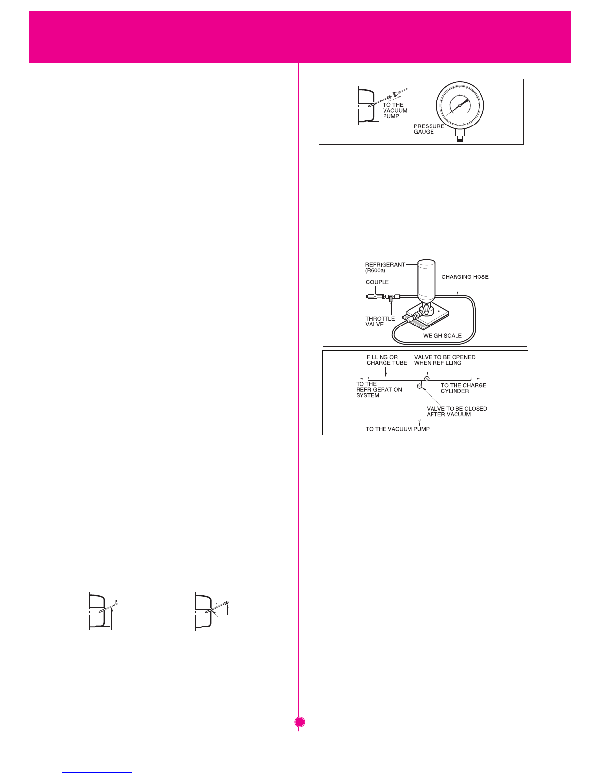
(No Fire, No Welding). Connect the Schrader valve to pump with the
coupler. And then turn the pump on for vacuum state (Figure 3). Let
the pump run until the low-pressure gauge indicates the vacuum
(gauge pressure 0, absolute pressure -1atm or -760mmHg).
Recommended vacuum time is 30 min. Charge the N2 gas in order
to check for leakage from welding points and the LOKRING. If
leakages are found, repair the defects and repeat the vacuum
process.
After the system is completely vacuumed, fill it with the
refrigerant R600a up to what has been specified at your refrigerator
Name Plate. The amount of refrigerant (R600a) must be precisely
measured within the error of ±2g by an electron scale (Figure 4).
REFRIGERANT (R600a) COUPLE CHARGING HOSE If you use the
manifold connected with both the refrigerant (R600a) cylinder and
the vacuum pump simultaneously, make sure the pump valve is
closed (Figure 5).
Connect the charging hose (that is connected to the refrigerant
(R600a) cylinder) to the Schrader valve installed on the service tube.
Then, charge the refrigerant (R600a) by controlling the Throttle
valve. When you do so, do not fully open the Throttle valve because
it may make damage to the compressor. Gradually charge the
refrigerant (R600a) by changing open and close the Throttle Valve
(5g at each time). The charging hose must use a one-way valve to
prevent the refrigerant refluence. Close the Schrader valve cap after
the refrigerant (R600a) is completely recharged.
After you completely recharge the refrigerant (R600a), perform the
leakage test by using a portable leakage detector or soapy water.
Test the low pressure (suction) parts in compressor off time and
high pressure parts in compressor on time. If the leakages are found,
restart from the refrigerant (R600a) discharging process and repairs
defects of leaks.
After the leakage test, check the temperature of each parts of the
cycle. Check with hands if the CONDENSER and the case
(HOT-LINE pipe) that is contacted to the door gasket are warm.
Confirm that frost is uniform distributed on the surface of the
EVAPORATOR.
Figure 3
Figure 4
Figure 5
Attach the service tube installed with a Schrader valve (one-way
valve) by using the LOKRING (Figure 2). Then, connect the Schrader
valve (one-way valve) to the pump that is connected to the
discharging hose leading to the outside. When discharging the
residual refrigerant, repeat 3 cycles that includes 3min of the pump
running pump off 30 sec of the compressor running.
POINT TO BE
BROKET
CHARGE TUBE
EXTENSION
SERVICE TUBE
EXTENSION
SCHRADER VALVE
(ONE-WAY VALVE)
LOKRING
Figure 2
Figure 1
SERVICING PRECAUTIONS
4

ITEMS SPECIFICATIONS
DIMENSIONS (mm)
595(W)X643(D)X1737(H)
595(W)X643(D)X1907(H)
NET WEIGHT (kg) 69/75
COOLING SYSTEM Fan Cooling
TEMPERATURE CONTROL Micom Control
DEFROSTING SYSTEM
Full Automatic
DOOR FINISH
Pre-Coated Metal or
Vinyl Coated Metal
OUT CASE Painted Steel Sheet
INNER CASE ABS
INSULATION Polyurethane Foam
DEFROSTING DEVICE Heater, Sheath
REFRIGERANT R600a (58g)
LUBRICATION OIL FREOL S10 (220 cc)
COMPRESSOR PTC Starting Type
EVAPORATOR Fin Tube Type
CONDENSER Wire Condenser
REFRIGERATOR
COMPARTMENT
DOOR BASKET
FREEZER COMPARTMENT
Bottle Guide (1EA or 0EA)
Egg Tray (1EA)
Basket (6EA or 4EA)
2 ℓ Bottle Basket (1EA)
Tray Drawer (3EA)
Stars two ** section
Tray Ice (1EA)
Transparent Shelf (3EA or 2EA)
Magic Crisper (1EA)
Vegetable Container (1EA)
1. Ref. No: GC-B379/409S*CA
2. Ref. No: GC- B379/409S*QA
ITEMS SPECIFICATIONS
DIMENSIONS (mm)
595(W)X643(D)X1737(H)
595(W)X643(D)X1907(H)
NET WEIGHT (kg) 69/75
COOLING SYSTEM Fan Cooling
TEMPERATURE CONTROL Micom Control
DEFROSTING SYSTEM
Full Automatic
DOOR FINISH
Pre-Coated Metal or
Vinyl Coated Metal
OUT CASE Painted Steel Sheet
INNER CASE ABS
INSULATION Polyurethane Foam
DEFROSTING DEVICE Heater, Sheath
REFRIGERANT R600a ( 58g)
LUBRICATION OIL FREOL S10 (220 cc)
COMPRESSOR PTC Starting Type
EVAPORATOR Fin Tube Type
CONDENSER Wire Condenser
REFRIGERATOR
COMPARTMENT
DOOR BASKET
FREEZER COMPARTMENT
Bottle Guide (1EA or 0EA)
Egg Tray (1EA)
Basket (4EA or 2EA)
2 ℓ Bottle Basket (1EA)
Dairy Corner (2EA)
Tray Drawer (3EA)
Transparent Shelf (3EA or 2EA)
Magic Crisper (1EA)
Vegetable Container (1EA)
SPECIFICATIONS
5
Stars two ** section
Tray Ice (1EA)
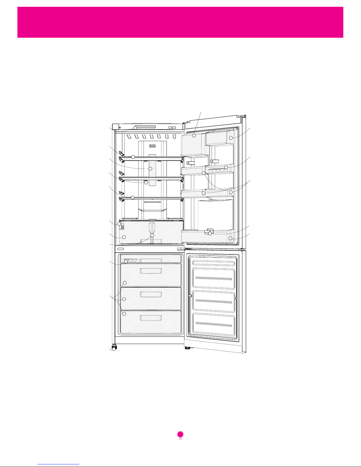
Removable
Glass Shelf
Tray Ice
Freezer
Compartment
Leveling Screw
Egg Tray
Basket Door
Models:
GC**379S*QA
GC**379S*CA
GC**409S*QA
GC**409S*CA
Cover LED
Multi-air Flow Duct
Glass Rem Shelf
Vitamin Plus System
(Special models)
Vegetable Drawer
Dairy Corner
(Special models)
Dairy Corner
(optional)
Guide Bottle (optional)
Basket Door
Guide
(optional)
Display
(optional)
PARTS IDENTIFICATION
6
This refrigerator allows the owner to change the door swing if desired.
The hinging of the doors can be changed to the opposite side
anytime you wish.
A Warning Electric Shock Hazard Disconnect electrical supply to
refrigerator before installing. Failure to do so could result in death or
serious injury.
When reversing the door swing :
• Read the instructions all the way through before starting.
• Handle parts carefully to avoid scratching paint.
• Set screws/bolts down by their related parts to avoid using them in
the wrong places.
• Provide a non-scratching work surface for the doors.
IMPORTANT
Once you begin, do not move the cabinet until door-swing reversal is
completed.
These instructions are for changing the hinges from the right side to
the left side-if you ever want to change the hinges back to the right
side, follow these same instructions and reverse all references to left
and right.
Before Removing the Doors, empty and Remove all the Door Baskets
of both Refrigerator/ Freezer Doors, including the Bank Dairy.
Close both doors before removing hinge pins.
CAUTION
Do not let either door drop to the floor.
Doing so could damage the Door Stop.
1
2
3
5
4
A
6
A
7
5
9
8
10
11
14
12
6
13
5
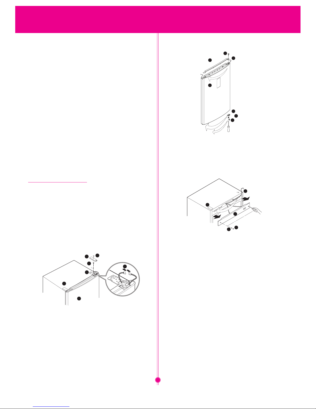
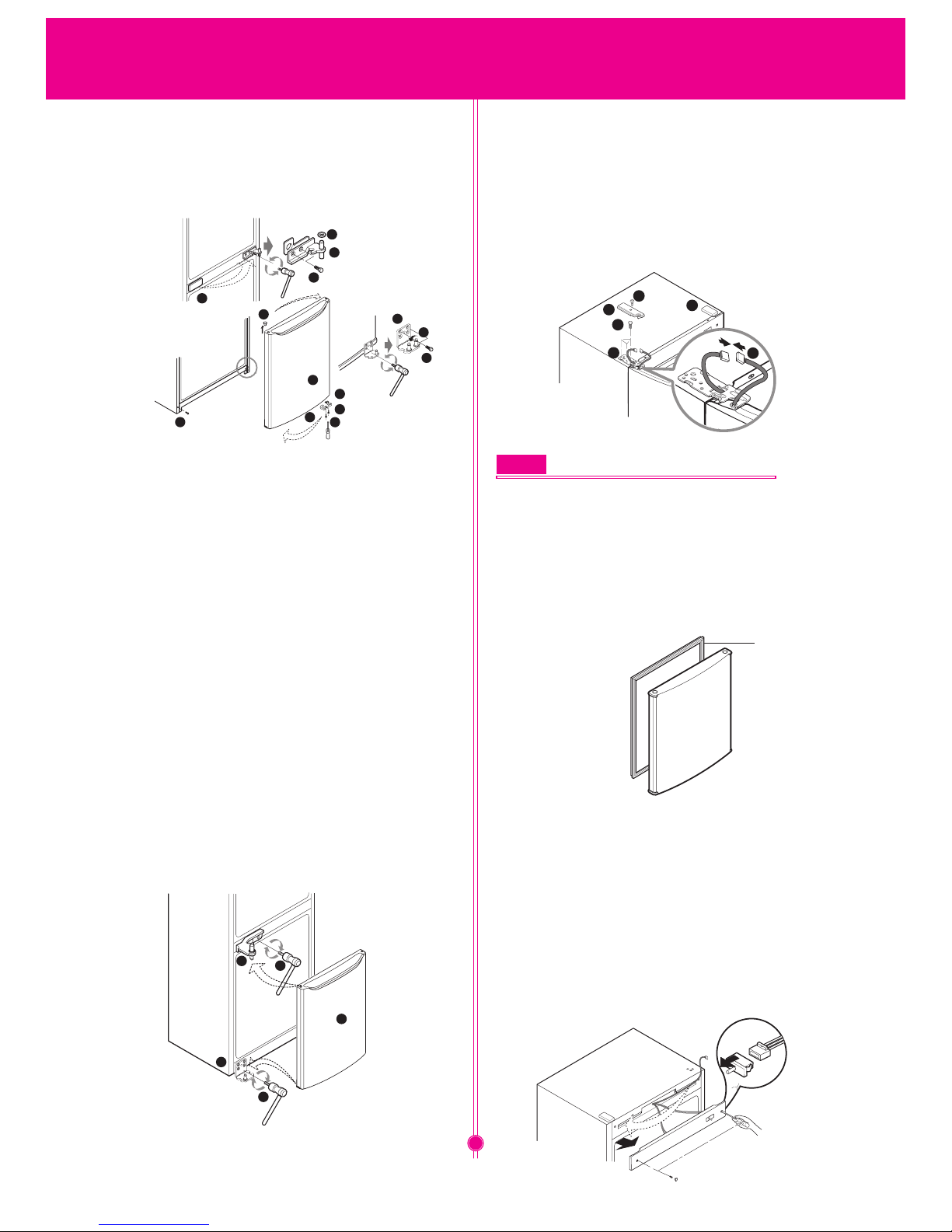
How to Reverse the Door
1. After unscrewing the screw (2) of cover hinge (1) on the
top, take off cover hinge and disconnect cable (5) (Only for
the exterior display type models). Unscrew bolts (3), which
fasten upper hinge (4) and remove upper hinge (4). Carefully
take off the refrigerator’s door (A).Remove cap (6).
2. Remove cap cover of door (7) (only for the exterior display
type models), pull out cable (5) and install it into the opening
on the opposite side of the door.
Set the cap cover of door (7) in its place.
3. Screw out the screw (8) located under the refrigerator
door (A) and move it emphasis (9) to the opposite side.
Fixate the screw.
4. Move plastic caps (10) (for all types display) and (11) (only
for of interior type display models) to the opposite side.
5. (Only for exterior type display). Press by the (-)
screwdriver and separate caps (12) of cover front (13) and
unscrew screws (14), remove cover front (13), then move
cable (5) to the opposite side. After installation cover
front (13), screw by parts (14) and cover it by caps (12).
INSTRUCTIONS FOR REVERSING DOOR SWING
7
NOTE
Reversing the doors is not covered by the warranty
1. DOOR
• Freezer Door
1. Refer to previous chapter "Instruction
for Reversing Door Swing".
2. Pull out the Door Gasket to remove from
the Door Foam Assembly, F.
GASKET
• Refrigerator Door
1. Refer to previous chapter "Instruction for Reversing
Door Swing".
2. Pull out the Door Gasket to remove from the
Door Foam Assembly, R.
2. DOOR SWITCH
1. Unplug the power cord from the outlet.
2. Loosen five screws in upper part and disconnect Top
Cover Front.
3. Disconnect Lead Wire from switch.
4. Disengage hook behind the
switch by pressing it
with hands.
17
15
16
27
26
B
20
19
18
25
24
21v
23
16
19
20
15
B
29
3
2
28
5
6
6. Unscrew bolts (15) of the middle hinge (16), rise up the
freezer door (B) to remove it. Take off cap cover (17) and
install it instead of middle hinge (16).
Unscrew bolts (18) of lower hinge (19) rotating it by opposite
of clockwise and than screw it in opposite side hole.
Unscrew the bolts (20), which is fixing lower hinge (19) &
bolt (21) on the case of the refrigerator. Unscrew the screw
(22)on the bottom of the case which is fixated closer (23) of
the freezer door (B) , move closer (23) to the opposite side
in appropriated place and fix it up.
Unscrew the screw (24)on the bottom of the case which is
fixated emphasis (25) of the freezer door (B) , move
emphasis (25) to the opposite side in appropriated place
and fix it up.
Move the upper cap (26) on the opposite side.
7. Attach removed lower hinge (19) to the hole, located on
the opposite side of the case and tighten it by screws (20).
Screw in bolt (21) in the case of the refrigerator on
the opposite side. Install freezer door (B) to the pin in the
lower hinge (19). Turn over removed middle hinge (16) axis
outwards, and tighten it by screws (15) (Tight carefully to
prevent scratching of the door). Install the washer (27) on
the middle hinge (16).
22
8. Install the refrigerator door (A) through matching holes
in the lower of the door and pin of the middle hinge (16).
Then install the upper hinge (28), supplied with
refrigerator by placing in the appropriated hole of the
refrigerator door (A). Connect the connector cable (5)
(only for exterior display type models). Fix the upper hinge
(28) by bolts (3). Install cover upper hinge (29) and
tighten it by screw (2). Input the cover (6) which is
supplied with refrigerator.
INSTRUCTIONS FOR REVERSING DOOR SWING
8
DISASSEMBLY
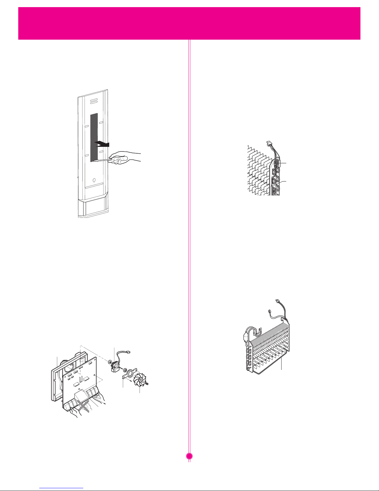
4. FAN AND FAN MOTOR
1. Remove freezer drawers.
2. Remove two cap, screws and loosen two screws in
Grille Fan.
3. Pull out the Grille Fan and Shroud, F.
4. Disconnect the housing of lead wire.
5. Separate the Fan Assembly.
6. Losse 2 screw fixed to the Bracket.
7. Pull out Shroud, F remove the Fan Motor Assembly.
8. Separate the Motor Bracket and Rubber.
5. DEFROST CONTROL ASSEMBLY
Defrost Control Assembly consists of Thermistor and Fuse,
Melting. Thermistor functions to defrost automatically and it
is attached to metal side of the Evaporator and senses
temperature.
Fuse, Melting is a kind of safety device for preventing
overheating of the Heater when defrosting.
At the temperature of 77°C, it stops the emission of heat
from the Heater.
1. Pull out the Shroud, F after removing the Grille.
2. Separate the connector connected with the Defrost Control
Assembly and replace new one.
Thermister
Fuse, Melting
6. HEATER, SHEATH
In this refrigerator, Heater, Sheath is used for defrosting
heater. During heating, the temperature of heater rises
about 300 ~ 350 . Therefore, be careful not to burn while
servicing.
1. After removing the Grille and Shroud, separate the
Heater, Sheath by disconnecting the connectors.
2. Exchanged Heater, Sheath and connected the housing.
Heater, Sheath
3. REFRIGERATOR ROOM LED LAMP
1. Unplug the power cord from the outlet.
2. Assemble in reverse order of disassembly. Replacement must be
the same specification as original.
3. Remove the Cover Lamp, R by pulling with a '–' type driver.
4. Pull the latch to take out LED Lamp.
5. Remove the LED lamp by unplugin connect.
9
DISASSEMBLY
1. COMPRESSOR
1. Role
The compressor intakes low temperature and low pressure gas
evaporated from Evaporator of the Refrigerator, and condenses this
gas to high temperature and high pressure gas, and then plays
delivering role to Condenser.
2. Composition
The Compressor is Composed of Compressor Apparatus
compressing gas, Compressor Motor moving Compressor
Apparatus and Case protecting Compressor Apparatus and Motor.
There is Relay Assembly (one set of PTC-Starter and Over Load
Protector (OLP)) in Compressor. On the other hand, because the
Compressor consists of 1/1000mm processing precision
components and is sealed after production in absence of dust or
humidity, deal and repair with care.
3. Note for Usage
(1) Be careful not to allow over-voltage and over-current.
(2) No Strike If applying forcible power or strike (dropping or careless
dealing), poor operation and noise may occur.
(3) Use proper electric components appropriate to the Compressor.
(4) Note to Keep Compressor.
If Compressor gets wet in the rain and rust in the pin of
Herme
tic Terminal, the result may be poor operation and poor
contact may cause.
(5) Be careful that dust, humidity, and flux welding don't inflow in the
Compressor inside in replacing the Compressor. Dust, humidity,
and flux due to welding which inflows to Cylinder may cause
lockage and noise.
2. PTC-STARTER
1. Composition of PTC-Starter
(1) PTC (Positive Temperature Coefficient) is a no-contact
semiconductor starting device which uses ceramic
material and this material consists of ВаТiOз.
(2) The higher the temperature is, the higher becomes the
resistance value. These features are used as starting
device for the Motor.
2. Role of PTC-Starter
(1) PTC is attached to Hermetic Compressor used for
Refrigerator, Show Case and starts Motor.
(2) Compressor for household refrigerator applies to
single-phase induction Motor.
For normal operation of the single-phase induction motor, in
the starting operation flows in both main coil and sub-coil.
After the starting is over, the current in subcoil is cut off. The
proper features of PTC play all the abo
ve roles. So, PTC is used
as a motor starting device.
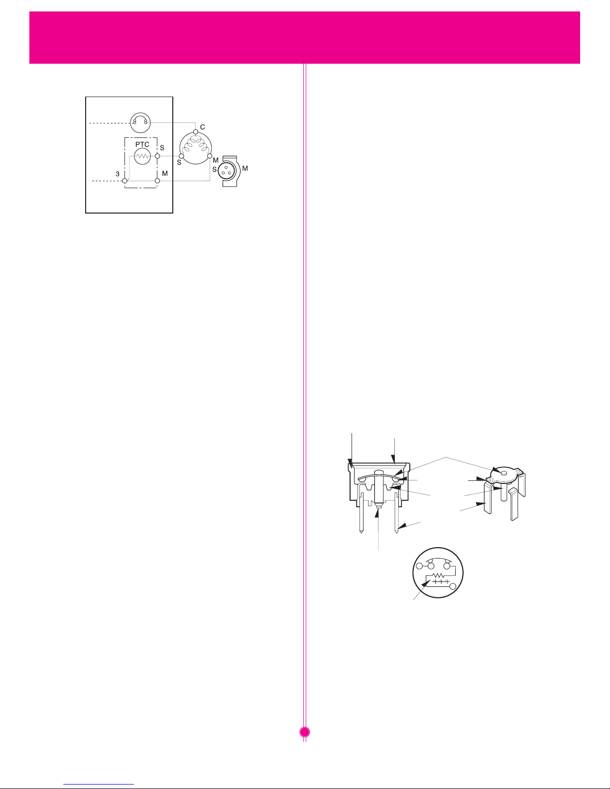
3. PTC-Applied Circuit Diagram
• According to Starting Method for the Motor
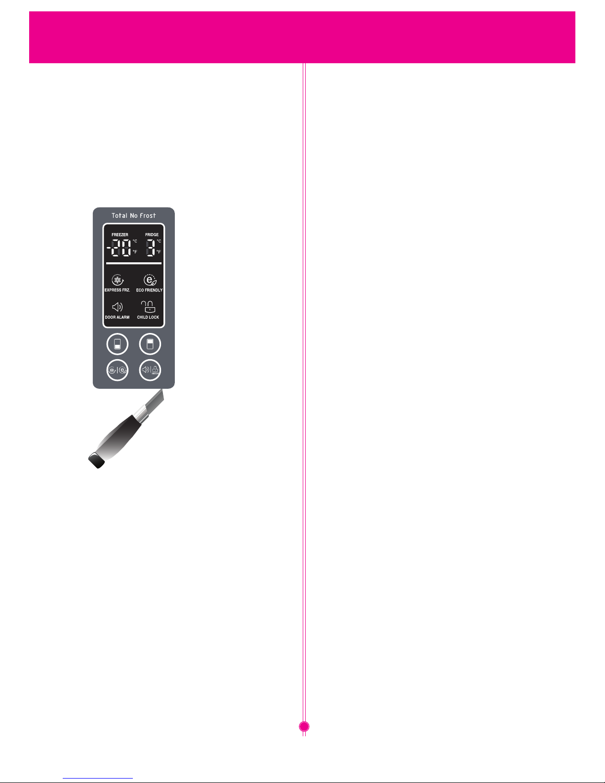
7. DISPLAY REMOVE
1. Insert the blade of a knife in the middle bottom of the
screen carefully.
2. Tilt the knife down until the display while latches do not come
out of the grooves.
3. Remove the display.
10
ADJUSTMENTDISASSEMBLY
OVERLOAD
PROTECTOR(O.L.P)
RELAY ASSEMBLY
PTC STARTER
RSIR
HERMETIC
TERMINAL
COMPRESSOR
MOTOR
4. Motor Restarting and PTC Cooling (1) For restarting after power
off during normal Compressor Motor operation, plug the power
cord after 5 min. for pressure balance of Refrigerating Cycle and
PTC cooling.
(2) During normal operation of the Compressor Motor, PTC
elements generate heat continuously. Therefore,
if PTC isn't cooled for a while after the power has been shut off,
Motor can't operate again.
5. Relation of PTC-Starter and OLP
(1) If the power is off during operation of Compressor and
the power is on before the PTC is cooled, (instant shut- off
within 2 min. or reconnect a power plug due to misconnecting),
the PTC isn't cooled and a resistance value grows. As a result,
current can't flow to the sub-coil and the Motor can't operate
and the OLP operates by flowing over current in only in the
main-coil.
(2) While the OLP repeats on and off operation about 3-5
times, PTC is cooled and Compressor Motor performs
normal operation.
If OLP doesn't operate when PTC is not cooled, Compressor
Motor is worn away and causes circuit-short and fire. Therefore,
use a properly fixed OLP without fail.
3. Note to Use PTC-Starter
(1) Be careful not to allow over-voltage and over-current.
(2) No Strike Don't apply a forcible power or strike.
(3) Keep apart from any liquid.
If liquid such as oil or water away enter the PTC, PTC materials it
may break due to insulation breakdown of the material itself.
(4) Don't change PTC at your convenience.
Don't disassemble PTC and mold. If the exterior to the
PTC-starter is damaged, resistance value is altered and it may
cause poor starting of the compressor motor may cause.
(5) Use a properly fixed PTC.
4. OLP (OVER LOAD PROTECTOR)
1. Definition of OLP
(1) OLP (OVER LOAD PROTECTOR) is attached to the
Hermetic Compressor and protects the Motor by cutting
off current in Compressor Motor in case of over-rising
temperature by Bimetal in the OLP.
(2) When over-voltage flows to Compressor motor, the
Bimetal works by heating the heater inside the OLP,
and the OLP protects Motor by cutting off current which
flows to the Compressor Motor.
2. Role of the OLP
(1) The OLP is attached to the Hermetic Compressor used
for the Refrigerator and Show Case and prevents the
Motor Coil from being started in the Compressor.
(2) Do not turn the Adjust Screw of the OLP in any way for
normal operation of the OLP.
(Composition and connection Diagram of OLP)
CONTACTING
POINT
COVER
BIMETAL
BIMETAL
HEATER
HEATER
TERMINALS
ADJUST
SCREW
CONTACTING
POINT
ADJUSTMENT
11
12
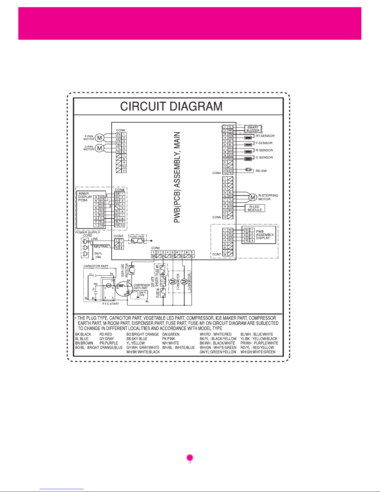
CIRCUIT DIAGRAM
P.No.: MEZ62581565
 Loading...