

LG LB-H1860PH, LB-H2460RU, LB-H1860FH, LB-H2460RH, LB-H2460PH Service Manual
...
Ceiling Duct Type
Air Conditioner
SERVICE MANUAL
MODELS: LB-H1860RH/RU/PH/FH
LB-H2460RH/RU/PH/FH
LB-G3660RH/RU/PH/FH
LB-G3680RH/FH
LB-E4880RH/FH
LB-E6080RH/FH

Contents
Functions .................................................................................................................................3
Product Specifications (Cooling & Heating)..........................................................................5
Dimensions ............................................................................................................................11
Refrigeration Cycle Diagram ................................................................................................13
Wiring Diagram ......................................................................................................................15
Operation Details ...................................................................................................................21
Installation of Indoor, Outdoor Unit .....................................................................................24
Test Running...........................................................................................................................35
Optional Operation.................................................................................................................37
E.S.P(External Static Pressure) Setting ...............................................................................39
How to set E.S.P ?..................................................................................................................40
Cycle........................................................................................................................................42
Cycle Troubleshooting Guide ...............................................................................................45
Electronic Parts Troubleshooting Guide .............................................................................46
Electronic Control Device .....................................................................................................49
Exploded View and Replacement Parts List .......................................................................50
Plasma Air cleaner .................................................................................................................66
–2–
Functions
Indoor Unit
Operation ON/OFF by Remote controller
Sensing the Room Temperature
Room temperature control
Starting Current Control
Time Delay Safety Control
Indoor Fan Speed Control
Soft Dry Operation Mode
Auto Operation(Auto Change Over)
Deice (defrost) control (Heating)
Auto Restart
–3–
Hot-start Control (Heating)
• The indoor fan stops until the evaporator piping temperature will be reached at 28°C.
High head height Drain pump(Optional)
• A standard drain-head height of up to 700mm is possible.
Central Control(Optional)
•
It is operating individually or totally by central control function.
Group Control(Optional Wiring)
Phase Control
PLASMA (Optional)
Telephone Control Operation (Optional)
•
Each controller can control 16 units and 8 controllers can connect.
•
It operates maximum 16 units by only one wired remote controller and each unit starts random to prevent overcurrent.
• Room temperature sensor. (Thermistor)
•
Maintains the room temperature in accordance with the Setting Temp.
• Indoor fan is delayed for 5 seconds at the starting.
• Restarting is inhibited for approx. 3 minutes.
• High, Med, Low
• Intermittent operation of fan at low speed.
• Although the air-conditioner is turned off by a power failure, it is restarted automatically previous operation mode after power supply.
• Fan speed is varied according to the state of dampers by micom.
• Calling from outside, you can start the air conditioner to
keep the room comfortable.
• Even though you went out with the air conditioner on, you
can turn it off using the phone outside.
• The function will be operated while in any operation mode wigh selecting the
function.
• The function is to be stopped while it is operating with selecting the function.
• The setting temperature and desired operation mode are automatically set by fuzzy rule.
• Both the indoor and outdoor fan stops during defrosting.
• Hot start after defrost ends.
–4–
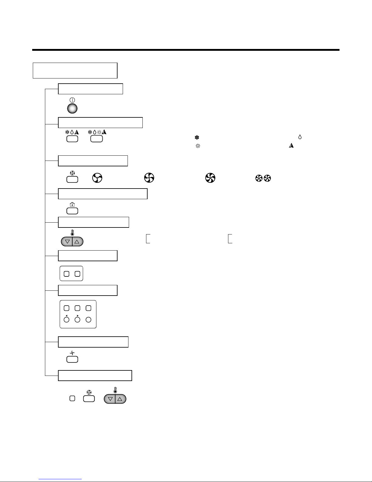
Remote Controller
Operation ON/OFF
Operation Mode Selection
Fan Speed Selection
Room Temperature Display
Temperature Setting
Setting the Timer
Weekly Program
(Cooling
model only)
(Heating
model only)
(Low) (Med) (High)
Cooling Operation Mode ( )
Heating Operation Mode ( ) Auto Operation Mode ( )
Soft Dry Operation Mode ( )
Fan Operation Mode
Phase Control Setting
HI AUTOMEDLO
Program Holiday
SET/CLR
MinHour
Week
Timer CancelTimer Cancel
Timer
: High:39°C ↔ LOW:11°C
: Fan Operates without cooling & heating
Cooling Heating
Down to 18°C
Up to 30°C
Down to 16°C
Up to 30°C
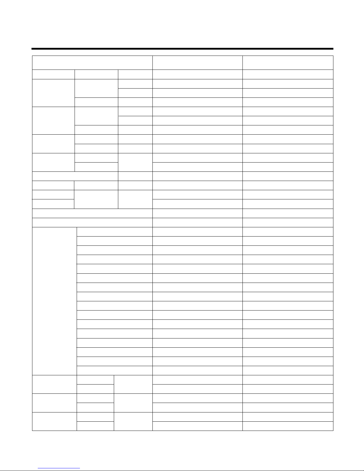
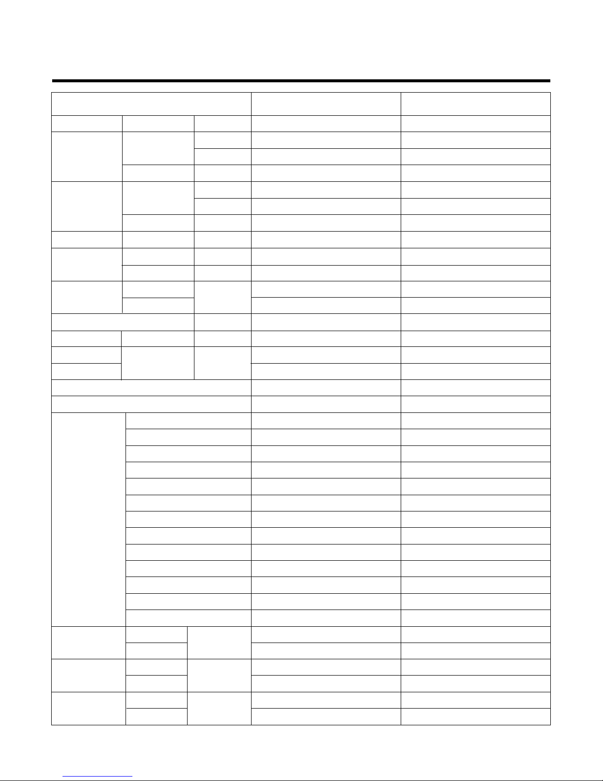
Product Specifications (Cooling & Heating)
–5–
Power Source Ø, V, Hz"
Cooling Capacity kcal/h(BTU/h)
W
Input W
Heating Capacity kcal/h(BTU/h)
W
Input W
Rated Load Amp. Cooling A
Heating A
Air Volumn Cooling(H/M/L)
CMM(m
3
/min)
Heating(H/M/L)
Refrigerant(R-407) g
Drain Hose In. Dia mm
Main Cable
No. X mm
2
Connecting Cable
Remote Control Type
Refigerant Control Type
Fuction Soft Dry
Timer
Self Diagnosis
Deice Operation
Hot Start
Zone Control(Optional)
Central Control(Optional)
Group Control(Optional wiring)
Weekly Programning
Thermistor
Drain Pump
Auto changeover(Auto Operation: CL)
Stand-by Consumption 0
Phase Control
Tele Control(Optional)
PLASMA(Optional)
Connecting Pipe Liquid Inch
Gas (mm)
Dimension Indoor mm
Outdoor (WxDxH)
Net Indoor Kg
Weight
Outdoor
1, 220-240, 50 1, 220-240, 50
4,536(18,000) 4,536(18,000)
5,275 5,275
2,000 2,000
4,546(18,000) -
5,275 2,000 -
10 10
10 -
16.5/14.5/13 16.5/14.5/13
16.5/14.5/13 1,250 1,250
22.6 22.6
3*2.5 3*2.5
5*0.75 4*0.75
L.C.D Wired L.C.D Wired
Capillary type Capillary type
Yes -
24 Hours On/Off 24 Hours On/Off
Yes Yes
Yes -
Yes Optional Optional
Optional Optional
Yes Yes
Yes Yes
Yes Yes
Optional Optional
Yes Yes
Yes Yes
Yes Yes
Optional Optional
Optional Optional
1/4(6.35) 1/4(6.35)
5/8(15.88) 5/8(15.88)
880*450*260 880*450*260
870*320*655 870*320*655
34 34
57 57
Model
LB-H1860RH LB-H1860FH

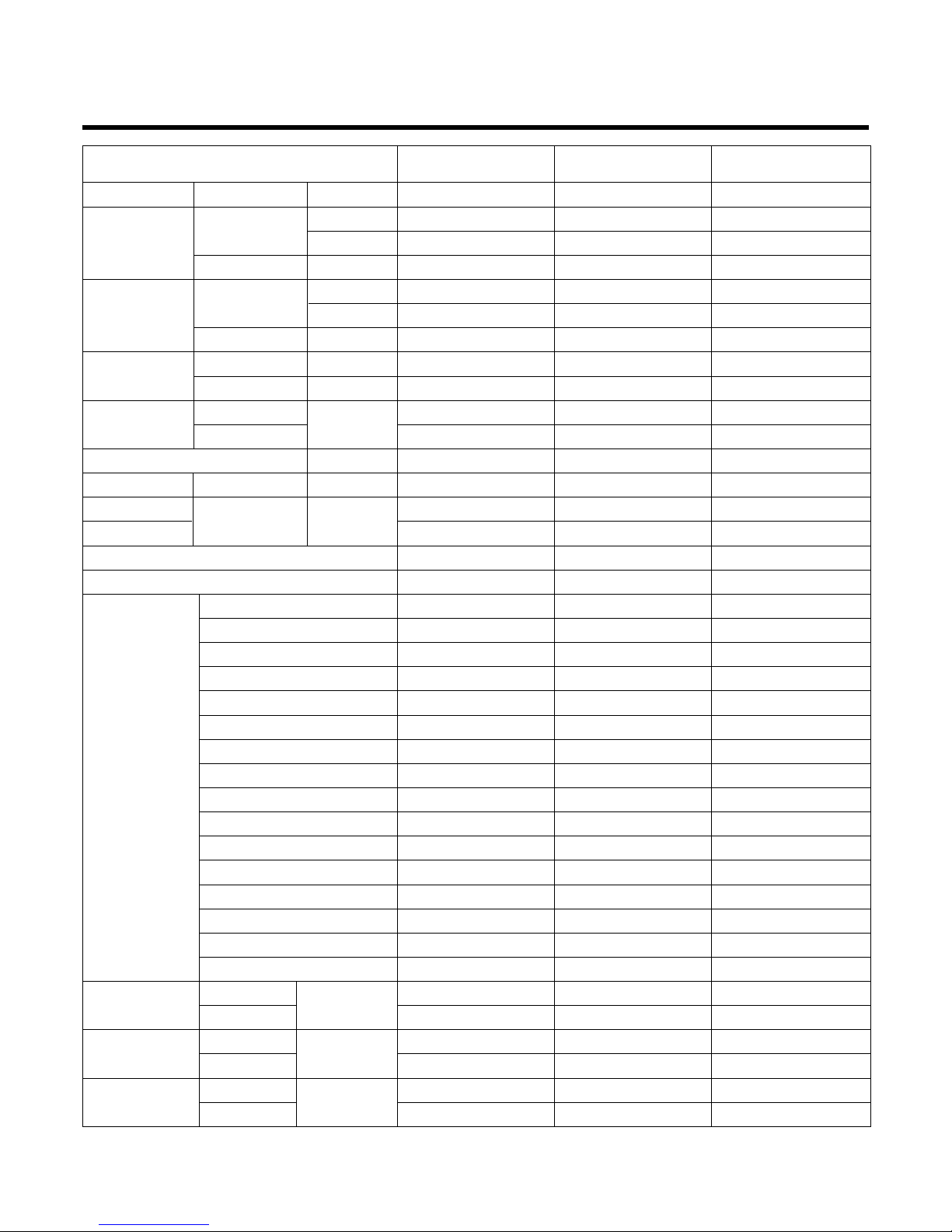
–6–
Power Source Ø, V, Hz"
Cooling Capacity kcal/h(BTU/h)
W
Input W
Heating Capacity kcal/h(BTU/h)
W
Input W
Rated Load Amp. Cooling A
Heating A
Air Volumn Cooling(H/M/L)
CMM(m
3
/min)
Heating(H/M/L)
Refrigerant(R-407) g
Drain Hose In. Dia mm
Main Cable
No. X mm
2
Connecting Cable
Remote Control Type
Refigerant Control Type
Fuction Soft Dry
Timer
Self Diagnosis
Deice Operation
Hot Start
Zone Control(Optional)
Central Control(Optional)
Group Control(Optional wiring)
Weekly Programning
Thermistor
Drain Pump
Auto changeover(Auto Operation: CL)
Stand-by Consumption 0
Phase Control
Tele Control(Optional)
PLASMA(Optional)
Connecting Pipe Liquid Inch
Gas (mm)
Dimension Indoor mm
Outdoor (WxDxH)
Net Indoor Kg
Weight
Outdoor
1, 220-240, 50 1, 220-240, 50
6,048(24,000) 6,048(24,000)
7,034 7,034
2,950 2,950
6,048(24,000) -
--
2,650 -
13 13
12 18/16.5/14 18/16.5/14
18/16.5/14 -
1,700 1,250
22.6 22.6
3*2.5 3*2.5
6*0.75 4*0.75
L.C.D Wired L.C.D Wired
Capillary type Capillary type
Yes -
24 Hours On/Off 24 Hours On/Off
Yes Yes
Yes -
Yes Optional Optional
Optional Optional
Yes Yes
Yes Yes
Yes Yes
Optional Optional
Yes Yes
Yes Yes
Yes Yes
Optional Optional
Optional Optional
1/4(6.35) 1/4(6.35)
5/8(15.88) 5/8(15.88)
880*450*260 880*450*260
870*320*655 870*320*655
33 35
60 60
Model
LB-H2460RH LB-H2460FH

–7–
Power Source Ø, V, Hz"
Cooling Capacity kcal/h(BTU/h)
W
Input W
Heating Capacity kcal/h(BTU/h)
W
Input W
Rated Load Amp. Cooling A
Heating A
Air Volumn Cooling(H/M/L)
CMM(m
3
/min)
Heating(H/M/L)
Refrigerant(R-407) g
Drain Hose In. Dia mm
Main Cable
No. X mm
2
Connecting Cable
Remote Control Type
Refigerant Control Type
Fuction Soft Dry
Timer
Self Diagnosis
Deice Operation
Hot Start
Zone Control(Optional)
Central Control(Optional)
Group Control(Optional wiring)
Weekly Programning
Thermistor
Drain Pump
Auto changeover(Auto Operation: CL)
Stand-by Consumption 0
Phase Control
Tele Control(Optional)
PLASMA(Optional)
Connecting Pipe Liquid Inch
Gas (mm)
Dimension Indoor mm
Outdoor (WxDxH)
Net Indoor Kg
Weight
Outdoor
3, 380-415, 50 3, 380-415, 50
8,820(3,500) 8,820(3,500)
10,257 10,257
4,050 4,050
9,072(36,000) -
14,067 -
3,470 -
6.6 6.6
5.9 32/29/26.5 32/29/26.5
32/29/26.5 -
1,900 1,900
22.6 22.6
4*2.5 4*2.5
5*0.75 4*0.75
L.C.D Wired L.C.D Wired
Capillary type Capillary type
Yes -
24 Hours On/Off 24 Hours On/Off
Yes Yes
Yes -
Yes Optional Optional
Optional Optional
Yes Yes
Yes Yes
Yes Yes
Optional Optional
Yes Yes
Yes Yes
Yes Yes
Optional Optional
Optional Optional
1/4(6.35) 1/4(6.35)
5/8(15.88) 5/8(15.88)
1,180*450*298 1,180*450*298
870*320*800 870*320*800
38 38
72 72
Model
LB-G3680RH LB-G3680FH
–8–
Power Source Ø, V, Hz"
Cooling Capacity kcal/h(BTU/h)
W
Input W
Heating Capacity kcal/h(BTU/h)
W
Input W
Rated Load Amp. Cooling A
Heating A
Air Volumn Cooling(H/M/L)
CMM(m
3
/min)
Heating(H/M/L)
Refrigerant(R-407) g
Drain Hose In. Dia mm
Main Cable
No. X mm
2
Connecting Cable
Remote Control Type
Refigerant Control Type
Fuction Soft Dry
Timer
Self Diagnosis
Deice Operation
Hot Start
Zone Control(Optional)
Central Control(Optional)
Group Control(Optional wiring)
Weekly Programning
Thermistor
Drain Pump
Auto changeover(Auto Operation: CL)
Stand-by Consumption 0
Phase Control
Tele Control(Optional)
PLASMA(Optional)
Connecting Pipe Liquid Inch
Gas (mm)
Dimension Indoor mm
Outdoor (WxDxH)
Net Indoor Kg
Weight
Outdoor
1, 220-240, 50 1, 220-240, 50 1, 220-240, 50
8,820(3,500) 8,820(3,500) 8,820(3,500)
10,257 10,257 10,257
4,270 4,270 4,100
9,072(36,000) 9,072(36,000) -
14,067 14,067 -
3,600 3,600 -
20 20 19
17 17 32/29/26.5 32/29/26.5 32/29/26.5
32/29/26.5 32/29/26.5 -
1,950 1,950 1,900
22.6 22.6 22.6
4*2.5 4*2.5 4*2.5
5*0.75 5*0.75 4*0.75
L.C.D Wired L.C.D Wired L.C.D Wired
Capillary type Capillary type Capillary type
Yes Yes -
24 Hours On/Off 24 Hours On/Off 24 Hours On/Off
Yes Yes Yes
Yes Yes -
Yes Yes Optional Optional Optional
Optional Optional Optional
Yes Yes Yes
Yes Yes Yes
Yes Yes Yes
Optional Optional Optional
Yes Yes Yes
Yes Yes Yes
Yes Yes Yes
Optional Optional Optional
Optional Optional Optional
1/4(6.35) 1/4(6.35) 1/4(6.35)
5/8(15.88) 5/8(15.88) 5/8(15.88)
1,180*450*298 1,180*450*298 1,180*450*298
870*320*800 870*320*800 870*320*800
38 38 38
72 72 72
Model
LB-G3660RH LB-G3660PH LB-G3660FH

–9–
Power Source Ø, V, Hz"
Cooling Capacity kcal/h(BTU/h)
W
Input W
Heating Capacity kcal/h(BTU/h)
W
Input W
Electhic Heater Capacity Kw
Rated Load Amp. Cooling A
Heating A
Air Volumn Cooling(H/M/L)
CMM(m
3
/min)
Heating(H/M/L)
Refrigerant(R-407C) g
Drain Hose In. Dia mm
Main Cable
No. X mm
2
Connecting Cable
Remote Control Type
Refigerant Control Type
Fuction Soft Dry
Timer
Self Diagnosis
Deice Operation
Hot Start
Zone Control(Optional)
Central Control(Optional)
Group Control(Optional wiring)
Weekly Programning
Thermistor
Drain Pump(Optional)
Auto changeover(Auto Operation: CL)
Stand-by Consumption 0
Connecting Pipe Liquid Inch
Gas (mm)
Dimension Indoor mm
Outdoor (WxDxH)
Net Indoor Kg
Weight
Outdoor
3, 380-415, 50 3, 380-415, 50
12,096(48,000) 12,096(48,000)
14,066 14,066
5,250 5,250
12,096(48,000) -
14,066 -
4,700 -
--
8.5 8.5
8-
40/35/30 40/35/30
40/35/30 -
4,900 4,900
22.6 22.6
4*3.5 4*3.5
5*1.25 4*1.25
L.C.D Wired L.C.D Wired
Capillary type Capillary type
Yes -
24 Hours On/Off 24 Hours On/Off
Yes Yes
Yes -
Yes Optional Optional
Optional Optional
Yes Yes
Yes Yes
Yes Yes
Optional Optional
Yes Yes
Yes Yes
3/8(9.52) 3/8(9.52)
3/4(19.05) 3/4(19.05)
1,230*680*370 1,230*680*370
900*370*1,220 900*370*1,220
70 70
95 90
Model
LB-E4880RH LB-E4880FH
–10–
Power Source Ø, V, Hz"
Cooling Capacity kcal/h(BTU/h)
W
Input W
Heating Capacity kcal/h(BTU/h)
W
Input W
Electhic Heater Capacity Kw
Rated Load Amp. Cooling A
Heating A
Air Volumn Cooling(H/M/L)
CMM(m
3
/min)
Heating(H/M/L)
Refrigerant(R-407C) g
Drain Hose In. Dia mm
Main Cable
No. X mm
2
Connecting Cable
Remote Control Type
Refigerant Control Type
Fuction Soft Dry
Timer
Self Diagnosis
Deice Operation
Hot Start
Zone Control(Optional)
Central Control(Optional)
Group Control(Optional wiring)
Weekly Programning
Thermistor
Drain Pump(Optional)
Auto changeover(Auto Operation: CL)
Stand-by Consumption 0
Connecting Pipe Liquid Inch
Gas (mm)
Dimension Indoor mm
Outdoor (WxDxH)
Net Indoor Kg
Weight
Outdoor
3, 380-415, 50 3, 380-415, 50
14,111(56,000) 14,111(56,000)
16,412 16,412
6,150 6,150
15,120(60,000) -
17,584 -
5,200 -
--
10 10
8.5 49/45/40/35 49/45/40/35
49/45/40/35 -
6,200 6,200
22.6 22.6
4*3.5 4*3.5
5*1.25 4*1.25
L.C.D Wired L.C.D Wired
Capillary type Capillary type
Yes -
24 Hours On/Off 24 Hours On/Off
Yes Yes
Yes -
Yes Optional Optional
Optional Optional
Yes Yes
Yes Yes
Yes Yes
Optional Optional
Yes Yes
Yes Yes
1/2(12.7) 1/2(12.7)
3/4(19.05) 3/4(19.05)
1,230*680*370 1,230*680*370
900*370*1,220 900*370*1,220
79 79
95 90
Model
LB-E6080RH LB-E6080FH
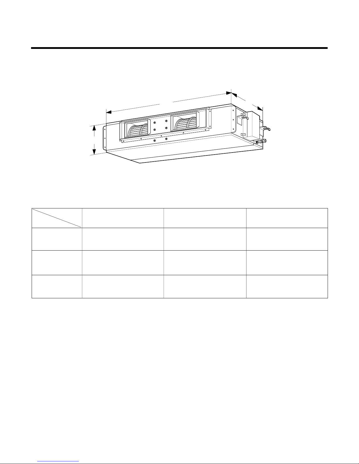
Dimensions
–11–
W
H
D
(1) Indoor Unit
DIM
MODEL
LB-H1860RH/FH
880 260 450
LB-H2460RH/FH
LB-G3660RH/PH/FH
1,180 298 450
LB-G3680RH/FH
LB-E4880RH/FH
1,230 370 680
LB-E6080RH/FH
W(mm) H(mm) D(mm)
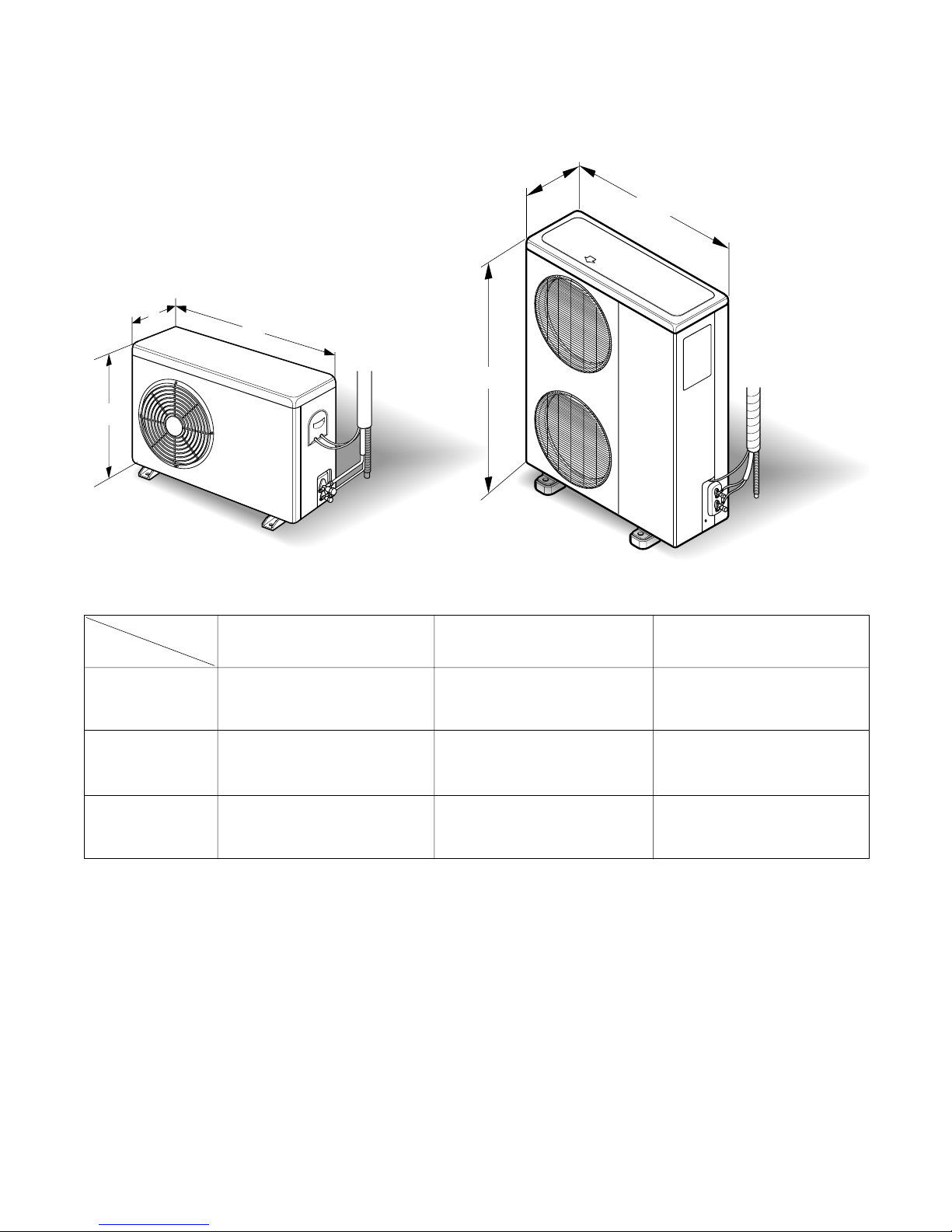
(2) Outdoor Unit
–12–
H
W
D
W
H
D
DIM
MODEL
LB-H1860RH/FH
870 655 320
LB-H2460RH/FH
LB-G3660RH/PH/FH
870 800 320
LB-G3680RH/FH
LB-E4880RH/FH
900 1,220 370
LB-E6080RH/FH
W(mm) H(mm) D(mm)
(18K/24K/36K) (48K/60K)
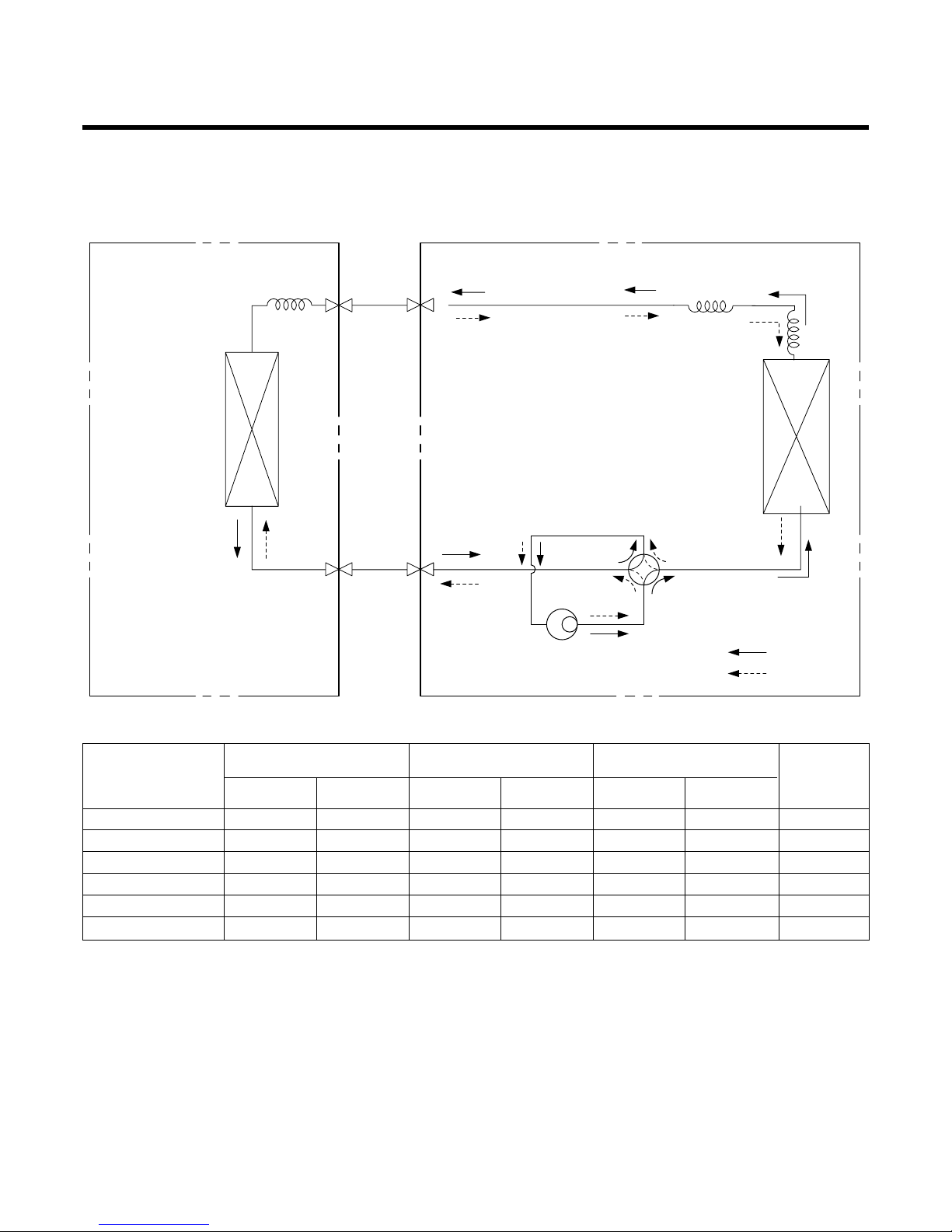
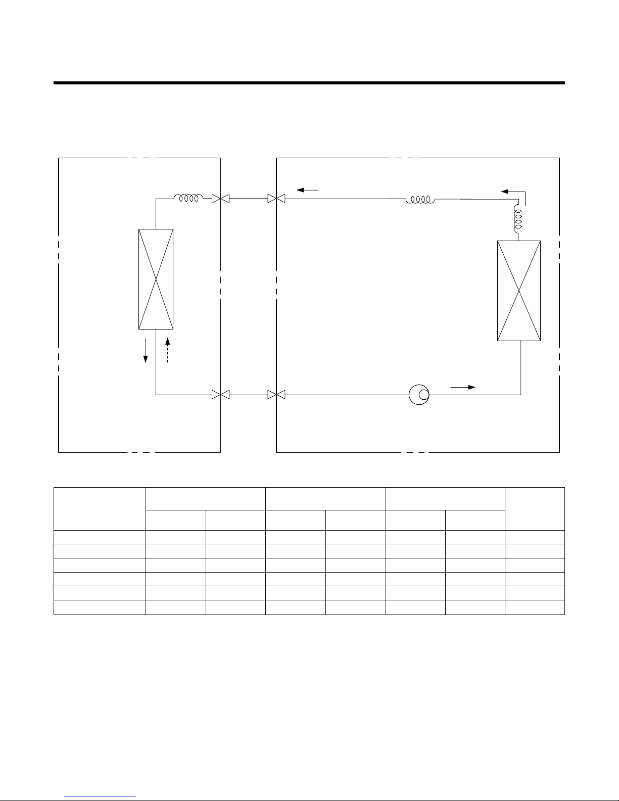
Refrigeration Cycle Diagram
•
HEAT PUMP (LB-H1860RH/LB-H2460RH/LB-G3680RH/LB-G3660RH/
LB-G3660PH/LB-E4880RH/LB-E6080RH)
–13–
INDOOR UNIT OUTDOOR UNIT
HEAT
EXCHANGER
HEAT
EXCHANGER
COMPRESSOR
GAS SIDE
LIQUID SIDE
COOLING
HEATING
REVERSING
VALVE
CAPILLARY TUBE
• Rated performance for refrigerant line length of: 7.5m
• If 18K Model is installed at a distance of 15m, 255g of refrigerant should be added (15-7.5)x30g=225g
LB-H1860RH 5/8" 1/4" 7.5 50 5 30 30
LB-H2460RH 5/8" 1/4" 7.5 50 5 30 30
LB-G3660RH/PH 5/8" 1/4" 7.5 50 5 30 40
LB-G3680RH 5/8" 1/4" 7.5 50 5 30 40
LB-E4880RH 3/4" 3/8" 7.5 50 5 30 40
LB-E6080RH 3/4" 1/2" 7.5 50 5 30 80
Pipe size(Diameter: ø) Piping length(m) Elevation(m)
MODEL
Gas Liquid Rated Max. Rated Max.
*Additional
refrigerant
(g/m)
–14–
• COOLING ONLY (LB-H1860FH/LB-H2460FH/LB-G3660FH/LB-G3680FH/
LB-E4880FH/LB-E6080FH)
INDOOR UNIT OUTDOOR UNIT
HEAT
EXCHANGER
(CONDENSER)
HEAT
EXCHANGER
(CONDENSER)
COMPRESSOR
GAS SIDE
LIQUID SIDE
CAPILLARY TUBE
• Rated performance for refrigerant line length of: .7.5m
• If 18K Model is installed at a distance of 15m, 225g of refrigerant should be added (15-7.5)x30g=225g
LB-H1860FH 5/8" 1/4" 7.5 50 5 30 30
LB-H2460FH 5/8" 1/4" 7.5 50 5 30 30
LB-G3660FH 5/8" 1/4" 7.5 50 5 30 40
LB-G3680FH 5/8" 1/4" 7.5 50 5 30 40
LB-E4880FH 3/4" 3/8" 7.5 50 5 30 40
LB-E6080FH 3/4" 1/2" 7.5 50 5 30 80
*Additional
refrigerant
(g/m)
Pipe size(Diameter: ø) Piping length(m) Elevation(m)
MODEL
Gas Liquid Rated Max. Rated Max.
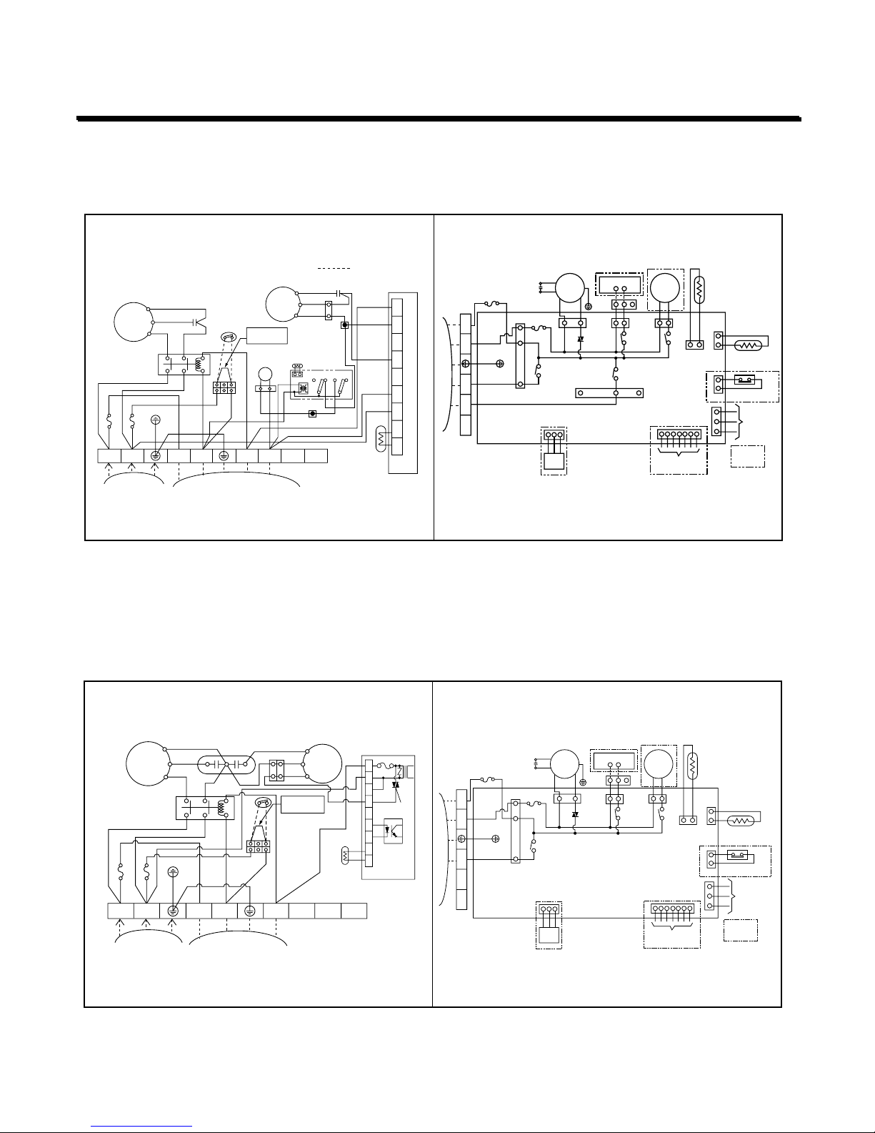
–15–
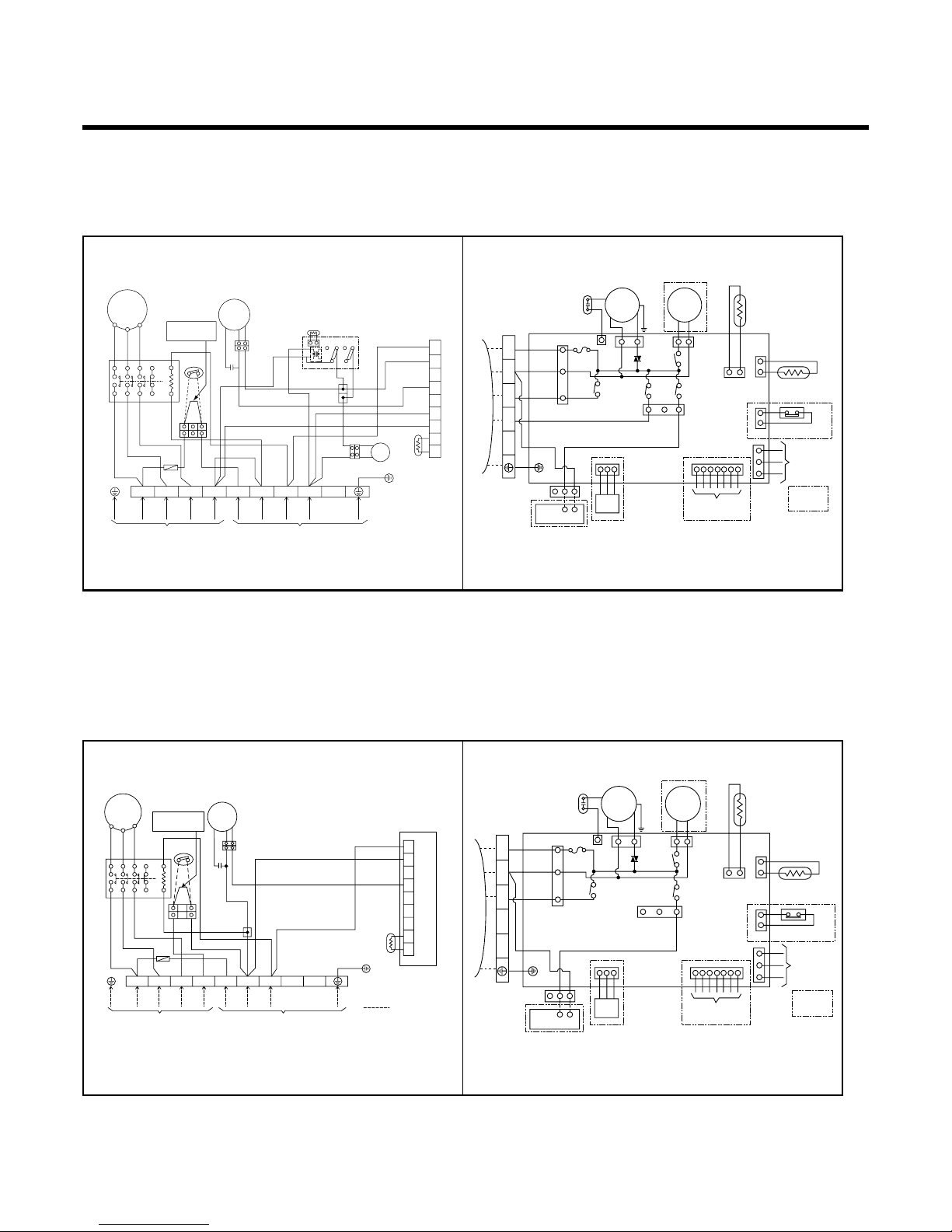
Wiring Diagram
HEAT PUMP
Model : LB-H1860RH
COOLING ONLY
Model : LB-H1860FH
OUTDOOR WIRING DIAGRAM INDOOR WIRING DIAGRAM
INDOOR
MOTOR
DRAIN
PUMP
BL
BK BK
BK
RD
BL
BR
GN/YL
YL
OR
BL
BL
BK
GN/YL
COMP
4 WAY
VENT
FUSE
250V 3.15A
TEMP.
THERMISTOR
PIPE
THERMISTOR
FLOAT S/W
REMOTE
CONTROL
ZONE
CONTROL
TERMINAL
BLOCK
TO OUTDOOR UNIT
3854A20166Z
FUSE
250V 5A
3(L) 4(N) 5 6 7
TRIAC
A/CL
UNIT
OPTION
VENTILATOR
T/B
COMP
R
S
42861
0
BL
BL
WH
WH
BR
BR
BL
BL
BL
RD
BL
BL
BR
GN/YL
GN/YL
CAPACITOR
CAPACITOR
REVERSING
VALVE
RD
BR
RD
WIRING OF FIELD
BK
OR
TB1
OR
YL
BKORBK
WH
BK
C
POWER
RELAY
FAN
MOTOR
FUSE 5A
FUSE 5A
POWER
INPUT
TO INDOOR UNIT
TERMINAL
BLOCK
3854A20128L
1(L)2(N
)
3(L)4(N
)
5
6
7
8
1
2
3
4
5
6
7
8
9
Low Ambient PCB
PIPE TH
TNS
NO
L1
L2
L3 L4
D.P
NC NO NC
pipe TH
TB2
REMOVE JUMP WIRE
WHEN CONNECTING
FIRE ALARM SYSTEM
OUTDOOR WIRING DIAGRAM INDOOR WIRING DIAGRAM
INDOOR
MOTOR
DRAIN
PUMP
BL
BK BK
RD
BL
BR
GN/YL
YL
OR
BL
BL
BK
GN/YL
COMP
VENT
FUSE
250V 3.15A
TEMP.
THERMISTOR
PIPE
THERMISTOR
FLOAT S/W
REMOTE
CONTROL
ZONE
CONTROL
TERMINAL
BLOCK
TO OUTDOOR UNIT
FUSE
250V 5A
3(L) 4(N) 5 6 7
TRIAC
A/CL
UNIT
OPTION
VENTILATOR
T/B
3854A20166M3854A30079G
8
COMP
R
S
H
42861
0
CF
BL
BL
YL
OR
OR
BK
BR
BR
BL
BR
BR
BL
BL
BL
BL
GN/YL
GN/YL
BK
BK
BK
BK
RD
CAPACITOR
RD
C
POWER
RELAY
FAN
MOTOR
FUSE 5A
FUSE 5A
POWER
INPUT
TO INDOOR UNIT
TERMINAL
BLOCK
1(L)2(N
)
3(L)4(N
)
5
6
7
8
WH
REMOVE JUMP WIRE
WHEN CONNECTING
FIRE ALARM SYSTEM
1
2
3
4
5
6
7
8
9
Low Ambient PCB
OUTDOOR TH
FUSE T3.15A
TRIAC
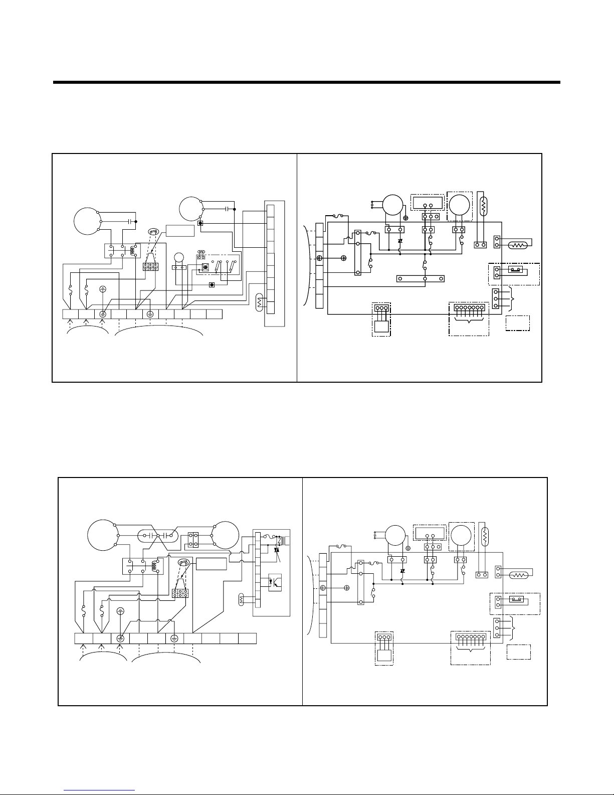
–16–
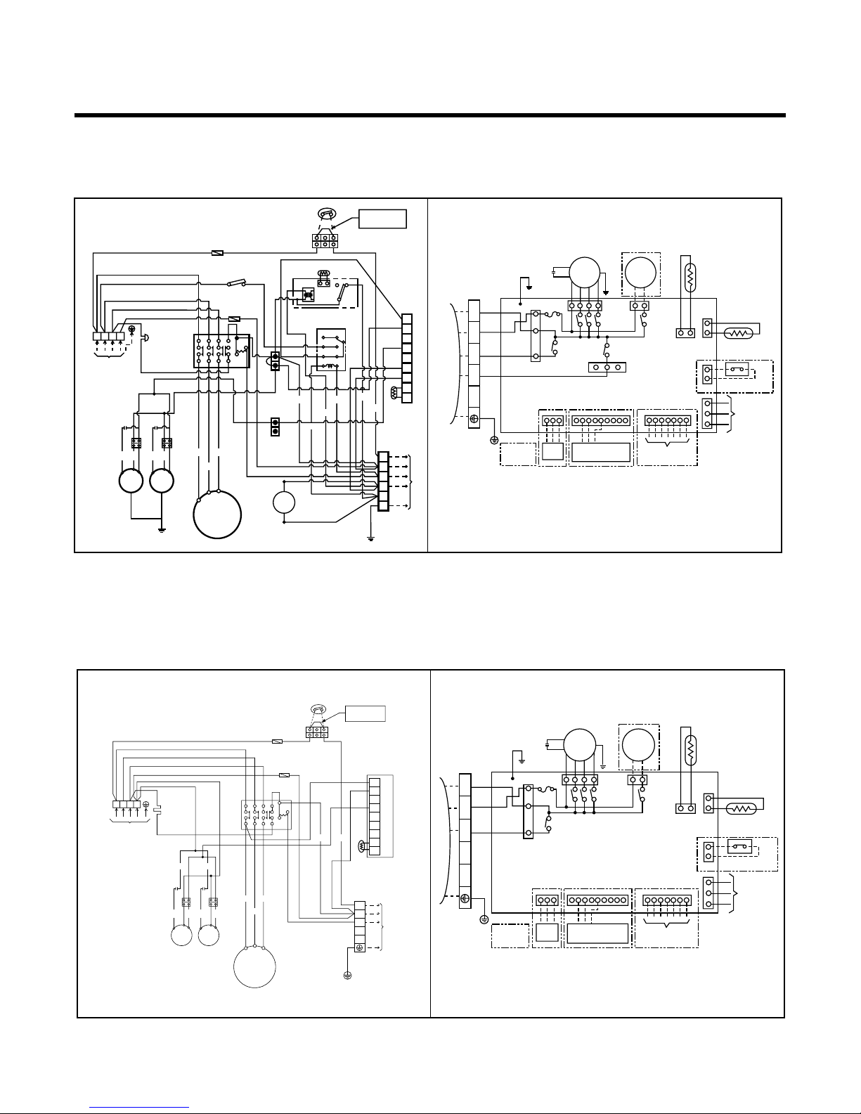
HEAT PUMP
Model : LB-H2460RH
COOLING ONLY
Model : LB-H2460FH
OUTDOOR WIRING DIAGRAM INDOOR WIRING DIAGRAM
INDOOR
MOTOR
DRAIN
PUMP
BL
BK BK
BK
RD
BL
BR
GN/YL
YL
OR
BL
BL
BK
GN/YL
COMP
4 WAY
VENT
FUSE
250V 3.15A
TEMP.
THERMISTOR
PIPE
THERMISTOR
FLOAT S/W
REMOTE
CONTROL
ZONE
CONTROL
TERMINAL
BLOCK
TO OUTDOOR UNIT
3854A20166Z
FUSE
250V 5A
3(L) 4(N) 5 6 7
TRIAC
A/CL
UNIT
OPTION
VENTILATOR
T/B
3854A20126S
COMP
R
S
42861
0
BL
BL
WH
WH
BR
BR
BL
BL
BL
RD
BL
BL
BR
GN/YL
GN/YL
CAPACITOR
CAPACITOR
REVERSING
VALVE
RD
BR
RD
BK
OR
TB1
OR
YL
BK
WH
BK
C
POWER
RELAY
FAN
MOTOR
FUSE 5A
FUSE 5A
POWER
INPUT
TO INDOOR UNIT
TERMINAL
BLOCK
1(L)2(N
)
3(L)4(N
)
5
6
7
8
1
2
3
4
5
6
7
8
9
Low Ambient PCB
PIPE TH
TNS
NO
L1
L2
L3 L4
D.P
NC NO NC
pipe TH
TB2
REMOVE JUMP WIRE
WHEN CONNECTING
FIRE ALARM SYSTEM
OUTDOOR WIRING DIAGRAM INDOOR WIRING DIAGRAM
INDOOR
MOTOR
DRAIN
PUMP
BL
BK BK
RD
BL
BR
GN/YL
YL
OR
BL
BL
BK
GN/YL
COMP
VENT
FUSE
250V 3.15A
TEMP.
THERMISTOR
PIPE
THERMISTOR
FLOAT S/W
REMOTE
CONTROL
ZONE
CONTROL
TERMINAL
BLOCK
TO OUTDOOR UNIT
FUSE
250V 5A
3(L) 4(N) 5 6 7
TRIAC
A/CL
UNIT
OPTION
VENTILATOR
T/B
3854A20166M3854A30079G
8
COMP
R
S
H
42861
0
CF
BL
BL
YL
OR
OR
BK
BR
BR
BL
BR
BR
BL
BL
BL
BL
GN/YL
GN/YL
BK
BK
BK
BK
RD
CAPACITOR
RD
C
POWER
RELAY
FAN
MOTOR
FUSE 5A
FUSE 5A
POWER
INPUT
TO INDOOR UNIT
TERMINAL
BLOCK
1(L)2(N
)
3(L)4(N
)
5
6
7
8
WH
REMOVE JUMP WIRE
WHEN CONNECTING
FIRE ALARM SYSTEM
1
2
3
4
5
6
7
8
9
Low Ambient PCB
OUTDOOR TH
FUSE T3.15A
TRIAC
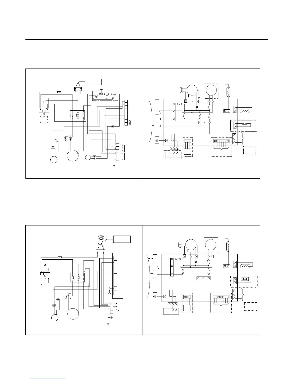
HEAT PUMP
Model : LB-G3660RH/PH
COOLING ONLY
–17–
OUTDOOR WIRING DIAGRAM INDOOR WIRING DIAGRAM
3854A20166A
3854A20126H
INDOOR
MOTOR
DRAIN
PUMP
YL
BR
OR
BR
BK
BL
RD
BK
BL BR
BL
BL
GN/YL
GN/YL
COMP
4 WAY
FUSE
250V 8A
TEMP.
THERMISTOR
PIPE
THERMISTOR
FLOAT S/W
REMOTE
CONTROL
ZONE
CONTROL
A/CL
UNIT
VENTILATOR
T/B
TERMINAL
BLOCK
1
(
L
)
2
(
N
)
4 3
5
TO OUTDOOR UNIT
TRIAC
VENT
OPTION
1TM
220-240V
1Ø, 50Hz
POWER SUPPLY
BK
L1 L2
T1 T2
A2
A1
BK
WH
WH
OR
RD
BK
TNS
NO
C TH
PIPE TH
NCNO NC
D.P
52C
LOW AMBIENT KIT.
WH
WH
WH
WH
F1
BK
Co
BKBKOR
OR
YL
FMo
20SV
RDOR
WH
BK
BK
BK
BL
T/B
BK BK
BK BK
GN/YL
Tmo
To the indoor unit
GN/YL
23
LN
1
2
3
4
5
6
BKWHRD
R
C
S
CM
Cr
PTCR
1
2
3
4
5
6
7
8
9
REMOVE JUMP WIRE
WHEN CONNECTING
FIRE ALARM SYSTEM
BK
OUTDOOR WIRING DIAGRAM INDOOR WIRING DIAGRAM
3854A20166C
3854A20126G
INDOOR
MOTOR
DRAIN
PUMP
YL
BR
OR
BR
BK
BL
RD
BL BR
BL
BL
GN/YL
GN/YL
COMP
FUSE
250V 8A
TEMP.
THERMISTOR
PIPE
THERMISTOR
FLOAT S/W
REMOTE
CONTROL
ZONE
CONTROL
A/CL
UNIT
OPTION
TERMINAL
BLOCK
1
(
L
)
2
(
N
)
4 3
5
TO OUTDOOR UNIT
TRIAC
VENTILATOR
T/B
VENT
REMOVE JUMP WIRE
WHEN CONNECTING
FIRE ALARM SYSTEM
BK
BK
1TM
220-240V
1Ø, 50Hz
POWER SUPPLY
BK
52C
L1 L2
T1 T2
A2
A1
BK
WH
F1
BK
WH
WH
Co
BKBKOR
OR
YL
FMo
WH
RD
WH
WH
WH
RD
GN/YL
Tmo
To the indoor unit
WH
GN/YL
23
LN
543
2(N) 1(L)
BKWHRD
R
C
S
CM
Cr
PTCR
1
2
3
4
5
6
7
8
9
LOW AMBIENT KIT
PIPE. TH
–18–
HEAT PUMP
Model : LB-G3680RH
COOLING ONLY
Model : LB-G3680FH
OUTDOOR WIRING DIAGRAM INDOOR WIRING DIAGRAM
3854A20166A
3854A20126X
CM
52C
T1
2143632
A
B
31
5
T2
T3
BL
BL
BL
BL
BK
BK
WH
PIPE. TH
BKBK
BK
BK
GN/YL
20SV
TMo
C TH
TNS
NO NONC NC
T/B1
T/B2
D.P
BK
OR
Co
OR
OR
OR
BK
BK
R
3Ø, 50Hz
380-415V
POWER SUPPLY
To the indoor unit
STN
1(L) 2(N) 3 4 5
BKBK
BL
BK
WH
WH
WH
WH
WH
WH
RD
YL
RD
RD
1
2
3
4
LOW AMBIENT CIRKIT
5
6
7
8
9
RD
FMo
WH
REMOVE JUMP WIRE
WHEN CONNECTING
FIRE ALARM SYSTEM
INDOOR
MOTOR
DRAIN
PUMP
YL
BR
OR
BR
BK
BL
RD
BK
BL BR
BL
BL
GN/YL
GN/YL
COMP
4 WAY
FUSE
250V 8A
TEMP.
THERMISTOR
PIPE
THERMISTOR
FLOAT S/W
REMOTE
CONTROL
ZONE
CONTROL
A/CL
UNIT
VENTILATOR
T/B
TERMINAL
BLOCK
1
(
L
)
2
(
N
)
4 3
5
TO OUTDOOR UNIT
TRIAC
VENT
OPTION
OUTDOOR WIRING DIAGRAM INDOOR WIRING DIAGRAM
3854A20166C
3854A20126U
CM
OR BK
OR
Co
RD
1
2
3
4
5
6
7
8
9
WH
BK
BL
LOW AMBIENT KIT
PIPE. TH
WH
T3
T2
T1
214632
A
B
31
35
52C
FUSE
R S T N 1(L) 3 4 5
GN/YL
To the indoor unit
3Ø, 50Hz
380-415V
POWER SUPPLY
WIRING OF FIELD
(CONNECTING WIRE)
TMo
TB
2(N)
BK
BKBK
BK
BL
BL
RD
RD
YL
WH
WH
WH
WH
FMo
REMOVE JUMP WIRE
WHEN CONNECTING
FIRE ALARM SYSTEM
WH
INDOOR
MOTOR
DRAIN
PUMP
YL
BR
OR
BR
BK
BL
RD
BL BR
BL
BL
GN/YL
GN/YL
COMP
FUSE
250V 8A
TEMP.
THERMISTOR
PIPE
THERMISTOR
FLOAT S/W
REMOTE
CONTROL
ZONE
CONTROL
A/CL
UNIT
OPTION
TERMINAL
BLOCK
1
(
L
)
2
(
N
)
4 3
5
TO OUTDOOR UNIT
TRIAC
VENTILATOR
T/B
VENT

–19–
HEAT PUMP
Model : LB-E4880RH
COOLING ONLY
Model : LB-E4880RH
INDOOR
MOTOR
DRAIN
PUMP
BR
BR
YL
ORRDBL
BL
RD
BK
GN/YL
BL
BL
BK
GN/YL
COMP
4WAY
FUSE
250V10A
ROOM
SENSOR
PIPE
SENSOR
FLOAT S/W
REMOTE
CONTROL
ZONE
CONTROL
OPTION
TERMINAL
BLOCK
1
(
L
)
2
(
N
)
4 3
5
TO OUTDOOR UNIT
3854A20166K3854A20235A
TELECONTROL/
CENTRAL CONTROL
A/CL
UNIT
OUTDOOR WIRING DIAGRAM INDOOR WIRING DIAGRAM
R
POWER SUPPLY
MAGNETIC
CONTACTER
CRANK-CASE
HEATER
STN
BK
BK
BK
BK
BK
WH
WH
WH
WH
RD
BK
BL
WH
D.P
TNS
NONO
pipe TH
NCNC
WH
OR
WH
BK
BK
OR
BK
BK
BK
WH
POWER
RELAY
12345631
T/B3
T/B2
T/B1
32
B
A
FAN
MOTOR
FAN
MOTOR
YL BK
OR
BK
T3
T2
T1
RD
BK
WH
COMP.
12
34
56
78
YL BK
OR
OR
BK
BK
BL
BL
BK
WH
CAPACITOR CAPACITOR
REVERSING
VALVE
BR
BL
BR
BL
GN/YL
GN/YL
TERMINAL BLOCK
To the indoor unit
1
2
3
4
5
6
1
2
3
4
5
6
7
8
9
BK
WHWH
BL
Fuse
(250V 5A)
Fuse
(250V 5A)
BK
BK
BK
PIPE TH
Low Ambient PCB
REMOVE JUMP WIRE
WHEN CONNECTING
FIRE ALARM SYSTEM
FUSE T3.15A
TRIAC
OUTDOOR WIRING DIAGRAM INDOOR WIRING DIAGRAM
INDOOR
MOTOR
DRAIN
PUMP
BR
BR
YL
ORRDBL
BL
RD
BL
BL
BK
GN/YL
COMP
FUSE
250V10A
ROOM
SENSOR
PIPE
SENSOR
FLOAT S/W
REMOTE
CONTROL
ZONE
CONTROL
OPTION
TERMINAL
BLOCK
1
(
L
)
2
(
N
)
4 3
5
TO OUTDOOR UNIT
3854A20166L3854A20078C
TELECONTROL/
CENTRAL CONTROL
A/CL
UNIT
GN/YL
GN/YL
TMo
To the indoor unit
Low Ambient PCB
2(N)
1(L)
3
4
5
F1
F1
RTM
POWER SUPPLY
STN
BK
BK
BK
BK
WH
RD
WH
WH
52C
12345631
32
B
A
FMo
49FMo
FMo
49FMo
BK
T3
T2
T1
RD
WH BK
BK
BK
WH
BL
WH
CM
YL BK
OR
Co Co
YLORBK
BR
OR
OR
BR
1
2
3
4
5
6
7
8
9
PIPE TH
BK
REMOVE JUMP WIRE
WHEN CONNECTING
FIRE ALARM SYSTEM
CRANK-CASE
HEATER
HEAT PUMP
Model : LB-E6080RH
COOLING ONLY
Model : LB-E6080FH
–20–
3854A20166N
OUTDOOR WIRING DIAGRAM INDOOR WIRING DIAGRAM
R
POWER SUPPLY
MAGNETIC
CONTACTER
STN
BK
BK
BK
WH
WH WH
WH
WH
RD
BK
HIGH PRESSURE S/W
WH
Deice PCB
CTH
TNS
NO
NC
WH
OR
WH
BK
BK
BK
BK
WH
POWER
RELAY
12345631
T/B1
T/B2
T/B3
32
B
A
FAN
MOTOR
FAN
MOTOR
YL BK
OR
BK
T3
T2
T1
RD
WH
COMP.
12
34
56
78
YL BK
OR
OR
BK
BK
BL
BL
BK
WH
CAPACITOR CAPACITOR
REVERSING
VALVE
BR
BL
BR
BL
GN/YL
GN/YL
TERMINAL BLOCK
To the indoor unit
1
2
3
4
5
6
1
2
3
4
5
6
7
8
9
BK
WHWH
YL
RD
Fuse
(250V 5A)
Fuse
(250V 5A)
BK
3854A20284A
BK
BK
PIPE TH
Low Ambient PCB
BK
REMOVE JUMP WIRE
WHEN CONNECTING
FIRE ALARM SYSTEM
CRANK-CASE
HEATER
INDOOR
MOTOR
DRAIN
PUMP
BR
BR
YL
ORBLBK
BL
RD
BK
GN/YL
BL
BL
YL
GN/YL
COMP
4WAY
FUSE
250V10A
ROOM
SENSOR
PIPE
SENSOR
FLOAT S/W
REMOTE
CONTROL
ZONE
CONTROL
OPTION
TERMINAL
BLOCK
1
(
L
)
2
(
N
)
4 3
5
TO OUTDOOR UNIT
TELECONTROL/
CENTRAL CONTROL
A/CL
UNIT
OUTDOOR WIRING DIAGRAM INDOOR WIRING DIAGRAM
3854A20078C
GN/YL
TMo
To the indoor unit
Low Ambient PCB
2(N)
1(L)
3
4
5
F1
F1
RTM
POWER SUPPLY
STN
BK
BK
BK
BK
WH
RD
WH
WH
52C
12345631
32
B
A
FMo
49FMo
FMo
49FMo
BK
T3
T2
T1
RD
WH BK
BK
BK
WH
BL
WH
CM
YL BK
OR
Co Co
YLORBK
BR
OR
OR
BR
1
2
3
4
5
6
7
8
9
PIPE TH
BK
REMOVE JUMP WIRE
WHEN CONNECTING
FIRE ALARM SYSTEM
CRANK-CASE
HEATER
INDOOR
MOTOR
DRAIN
PUMP
BR
BR
YL
ORBLBK
BL
RD
BL
BL
YL
GN/YL
COMP
FUSE
250V10A
ROOM
SENSOR
PIPE
SENSOR
FLOAT S/W
REMOTE
CONTROL
ZONE
CONTROL
OPTION
TERMINAL
BLOCK
1
(
L
)
2
(
N
)
4 3
5
TO OUTDOOR UNIT
3854A20166P
TELECONTROL/
CENTRAL CONTROL
A/CL
UNIT
GN/YL
–21–
Operation Details
(1) The function of main control
1. Time Delay Safety Control
• 3min The compressor is ceased for 3minutes to balance the pressure in the refrigeration cycle.
(Protection of compressor)
• 30sec The 4-way valve is ceased for 30sec. to prevent abnormal noise when the Heating operation is OFF or
switched to the other operation mode while compress is off.
While compressor is running, it takes 3~5 seconds to switch.
2. Soft-Dry Operation
• The indoor fan speed is automatically set to the low, and fan speed control is not available because of already
being set to the best speed for Dry Operation by Micom Control.
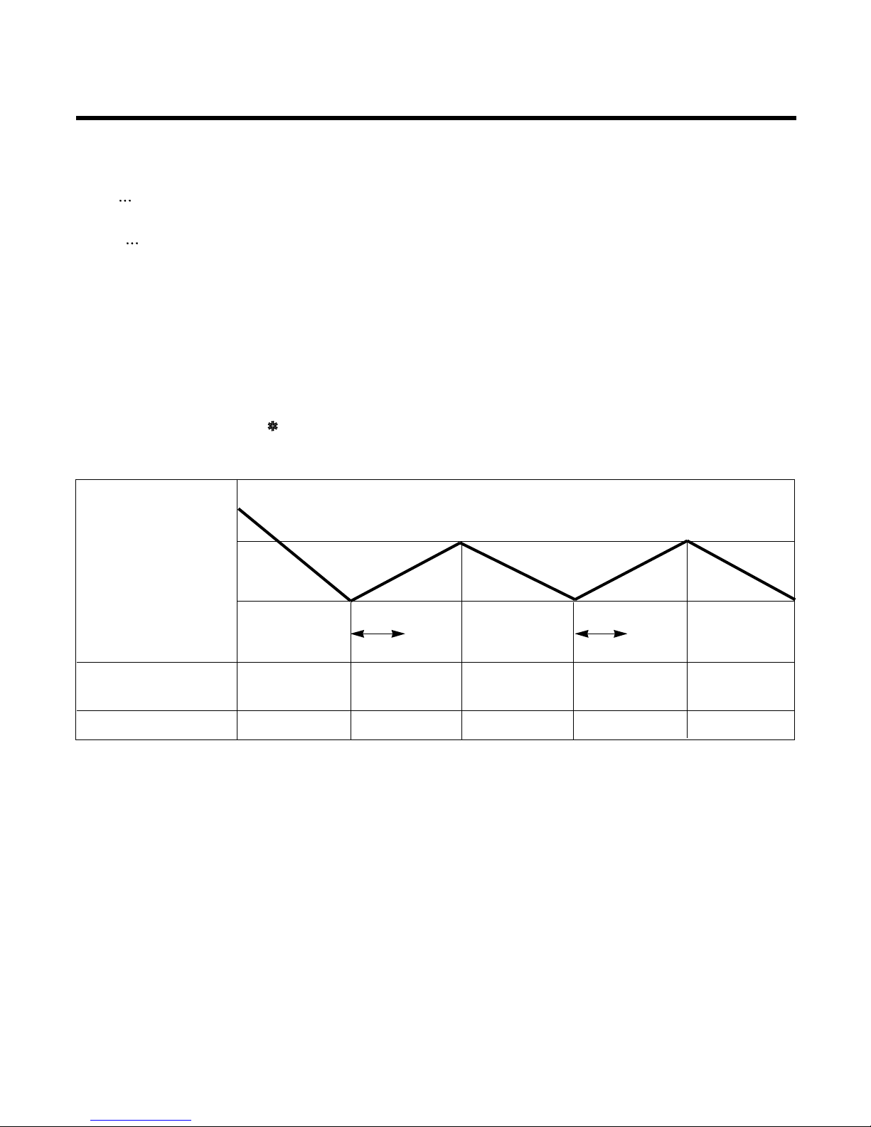
3. Cooling Mode Operation
• When selecting the Cooling( ) Mode Operation, the unit will operate according to the setting by the remote con-
troller and the operation diagram is as follows.
Intake Air temp.
SET TEMP.+0.5°C
(COMP. ON)
SET TEMP
SET TEMP. -0.5°C
(COMP. OFF)
Selected Selected Selected
fan speed fan speed fan speed
COMPRESSOR ON OFF ON OFF ON
INDOOR FAN Low Low
More than
3 minutes
More than
3 minutes
–22–
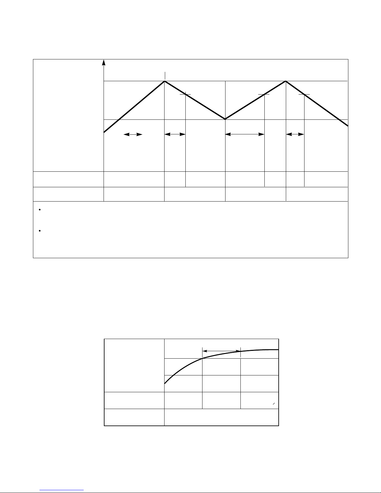
4. Heating Mode Operation (Except Cooling Model)
The unit will operate according to the setting by the remote controller and the operation diagram is shown as following.
5. Hot-Start Control
• The indoor fan stops until the evaporator piping temperature will be reached to 25°C.
• The operation diagram is as following.
PIPING
TEMPERATURE
1min
COMPRESSOR
INDOOR FAN
ON
OFF LOW
Selected
fan speed
22°C
25°C
Intake Air temp.
Setting temp.+3°C
(Compressor OFF)
Setting temp.
(Compressor ON)
INDOOR FAN
COMPRESSOR ON OFF ON OFF
A point; While the indoor Heat-Exchanger temperature is higher than 40°C fan operates at low speed, when
it becomes lower than 40˚C fan stops.
B point; When the indoor Heat-Exchanger temperature is higher than 51(42)°C, fan operates at selected fan
speed, when it becomes lower than 48(39)°C, the fan operates at low speed.
Selecting fan
speed
minimum
10sec.
1min
A
A
minimum
1min.
minimum
10sec.
B
 Loading...