

LG LB-H2460CL, LB-H1860CL, LB-H1860HP, LB-H2460HP, LB-H2460BL Service Manual
...
Ceiling Duct Type Air Conditioner
SVC MANUAL(Exploded View)
MODEL : LB-H1860HL/CL/HP/AL
LB-H1861BL
LB-H2460HL/CL/HP/BL/AL
LB-H2461BL
LB-G3680HL/CL/HP/BL/BS/AL
CAUTION
Before Servicing the unit, read the safety precautions in General SVC manual.
Only for authorized service personnel.
Internal Use Only
http://biz.lgservice.com

Contents
Model number Nomenclature..................................................................................................3
Functions .................................................................................................................................4
Product Specifications (Cooling & Heating)..........................................................................6
Dimensions ..............................................................................................................................8
Refrigeration Cycle Diagram ................................................................................................10
Wiring Diagram ......................................................................................................................12
Operation Details ...................................................................................................................15
Installation of Indoor, Outdoor Unit .....................................................................................18
3-way Valve ............................................................................................................................35
Cycle........................................................................................................................................40
Cycle Troubleshooting Guide ...............................................................................................43
Electronic Parts Troubleshooting Guide .............................................................................44
Electronic Control Device .....................................................................................................47
Exploded View ........................................................................................................................48
- 2 -
Copyright ©2008 LG Electronics. Inc. All right reserved.
Only for training and service purposes
LGE Internal Use Only
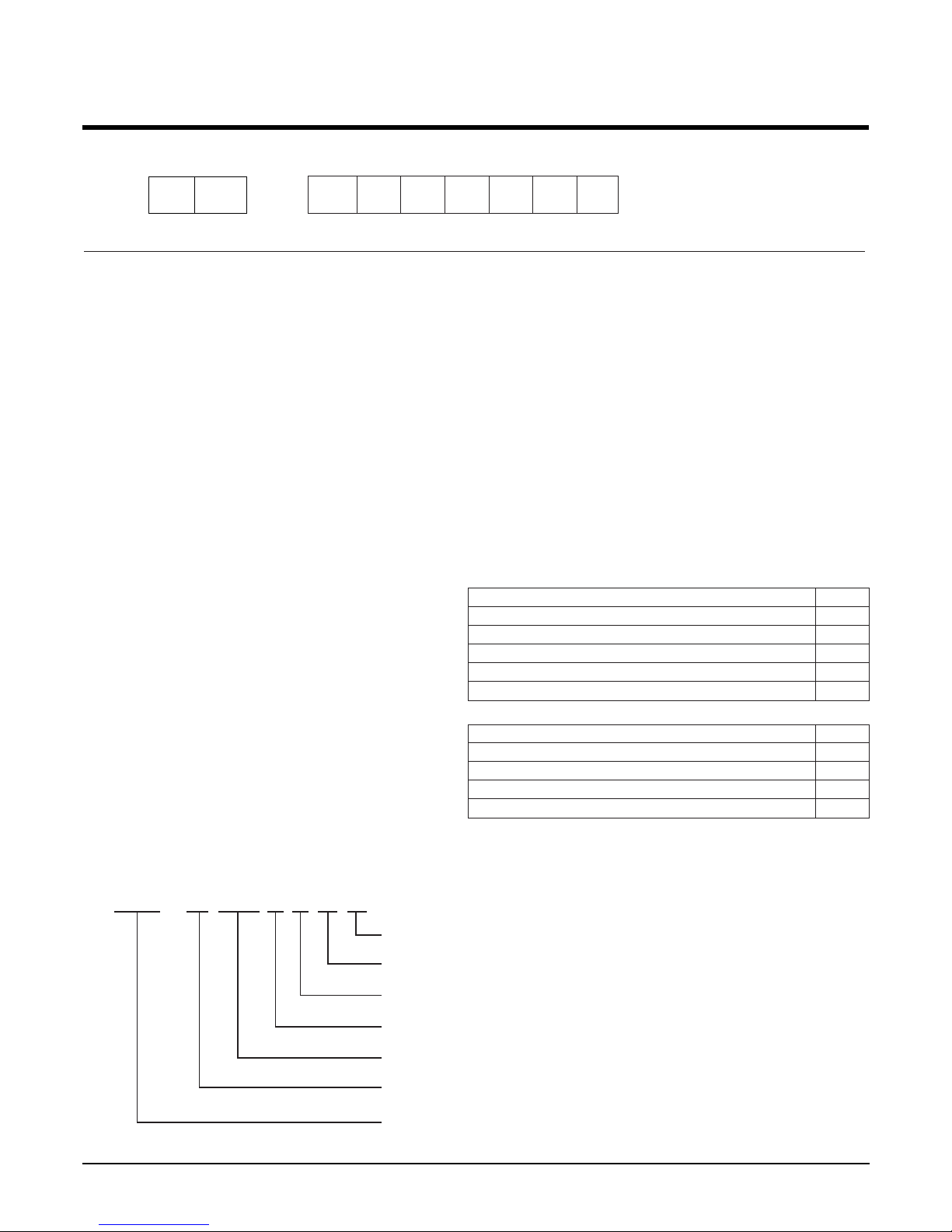
Model Number Nomenclature
- 3 -
Copyright ©2008 LG Electronics. Inc. All right reserved.
Only for training and service purposes
LGE Internal Use Only
12
LB
Code Type Code of Model Meaning
1 Producing Center/ A~Z
L: ChangWon R22, A: ChangWon R410A, C: ChangWon R407C
Refrigerant
2 Type of Air conditioner A~Z B: Ceiling Duct Type Air conditioner
3 Chassis A~Z Name of tool of unit ex) H : BH chassis
4,5 Capacity(Btu/h) 1~9 Cooling/Heating Capacity
Ex. "18" ➔ 18,000Btu/h
6 Electric Range 1~9 Electric Standard [V/Hz/Phase]
1 : 115/60/1 2 : 220/60/1 3 : 208-230/60/1
5 : 200-220/50/1 6 : 220-240/50/1 7 : 100/50(60)/1
8 : 380-415/50/3 9 : 380/60/3 B : 208-230/60/3
7 Serial No. 0~9
8 Heating/Cooling/Fin Type A~Z
9 Option A~Z
ex)
-
Basic Heat Pump H
Basic Cooling only C
Gold Fin Heat Pump B
Gold Fin Cooling only A
Basic L
Plasma Air Purifier A
Drain Pump P
High/Low Pressure Switch S
Low Static Motor G
3456789
H1860HL
LB-H1860HL
Basic
Heat Pump Basic Fin(PCM)
0 Series
220-240V/50Hz/1Ø
18,000 Btu
H chassis
LG Changwon R22 Ceiling Duct Type Air conditioner
- 4 -
Copyright ©2008 LG Electronics. Inc. All right reserved.
Only for training and service purposes
LGE Internal Use Only
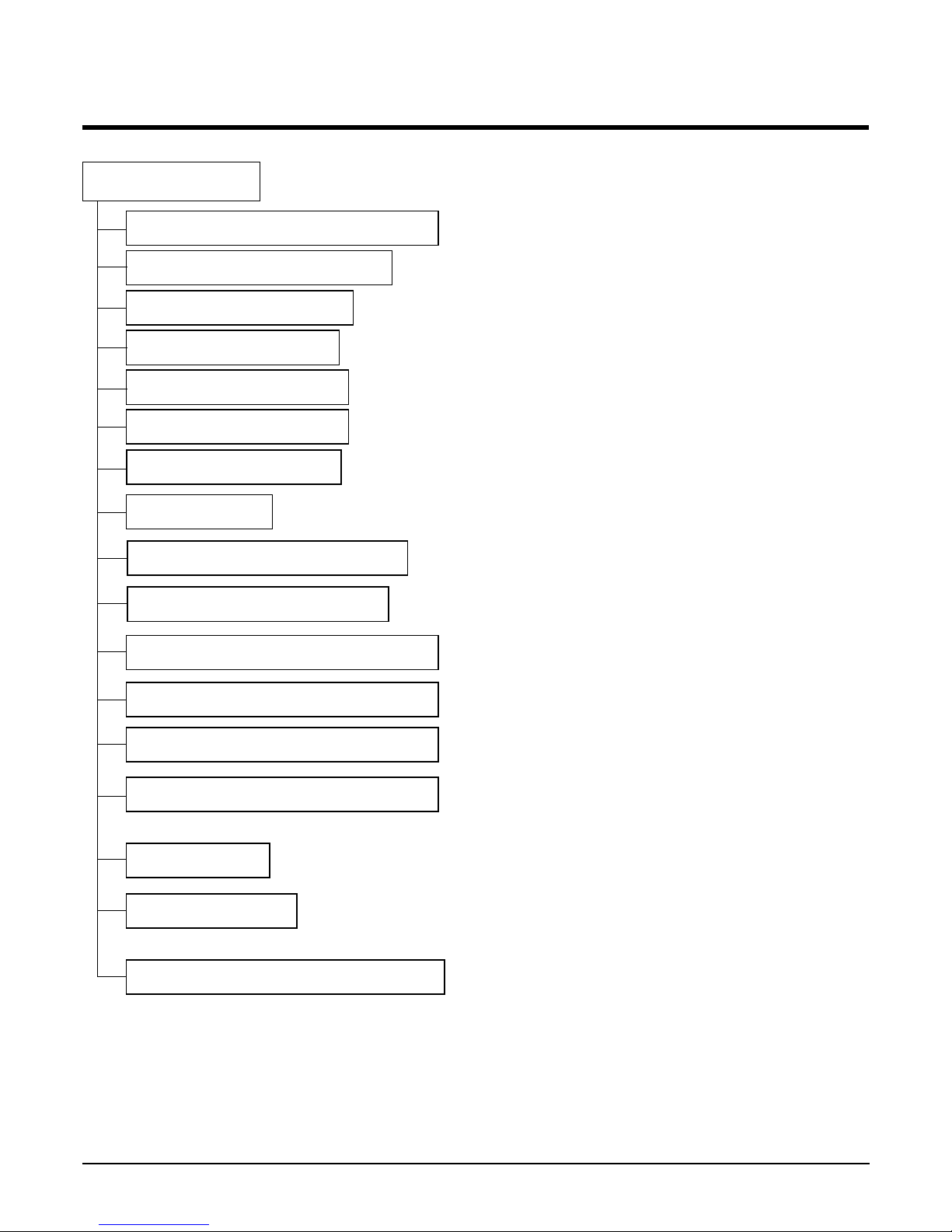
Functions
Indoor Unit
Operation ON/OFF by Remote controller
Sensing the Room Temperature
Room temperature control
Starting Current Control
Time Delay Safety Control
Indoor Fan Speed Control
Soft Dry Operation Mode
Auto Operation(Auto Change Over)
Deice (defrost) control (Heating)
Auto Restart
Hot-start Control (Heating)
• The indoor fan stops until the evaporator piping temperature will be reached at 28°C.
High head height Drain pump(Optional)
• A standard drain-head height of up to 700mm is possible.
Central Control(Optional)
•
It is operating individually or totally by central control function.
Group Control(Optional Wiring)
Phase Control
PLASMA (Optional)
Telephone Control Operation (Optional)
•
Each controller can control 16 units and 8 controllers can connect.
•
It operates maximum 16 units by only one wired remote controller and each unit starts random to prevent overcurrent.
• Room temperature sensor. (Thermistor)
•
Maintains the room temperature in accordance with the Setting Temp.
• Indoor fan is delayed for 5 seconds at the starting.
• Restarting is inhibited for approx. 3 minutes.
• High, Med, Low
• Intermittent operation of fan at low speed.
• Although the air-conditioner is turned off by a power failure, it is restarted automati-
cally previous operation mode after power supply.
• Fan speed is varied according to the state of dampers by micom.
• Calling from outside, you can start the air conditioner to
keep the room comfortable.
• Even though you went out with the air conditioner on, you
can turn it off using the phone outside.
• The function will be operated while in any operation mode wigh selecting the
function.
• The function is to be stopped while it is operating with selecting the function.
• The setting temperature and desired operation mode are auto-
matically set by fuzzy rule.
• Both the indoor and outdoor fan stops during defrosting.
• Hot start after defrost ends.
- 5 -
Copyright ©2008 LG Electronics. Inc. All right reserved.
Only for training and service purposes
LGE Internal Use Only
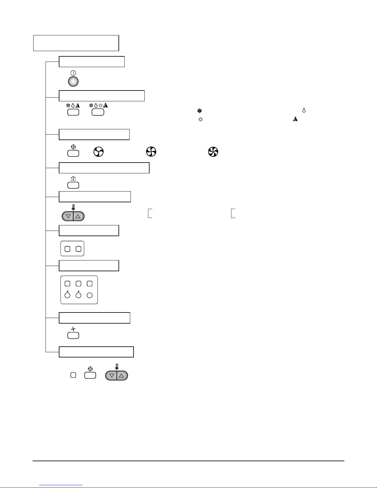
Remote Controller
Operation ON/OFF
Operation Mode Selection
Fan Speed Selection
Room Temperature Display
Temperature Setting
Setting the Timer
Weekly Program
(Cooling
model only)
(Heating
model only)
(Low) (Med) (High)
Cooling Operation Mode ( )
Heating Operation Mode ( ) Auto Operation Mode ( )
Soft Dry Operation Mode ( )
Fan Operation Mode
Phase Control Setting
HIMEDLO
Program Holiday
SET/CLR
MinHour
Week
Timer CancelTimer Cancel
Timer
: High:39°C ↔ LOW:11°C
: Fan Operates without cooling & heating
Cooling Heating
Down to 18°C
Up to 30°C
Down to 16°C
Up to 30°C

- 6 -
Copyright ©2008 LG Electronics. Inc. All right reserved.
Only for training and service purposes
LGE Internal Use Only
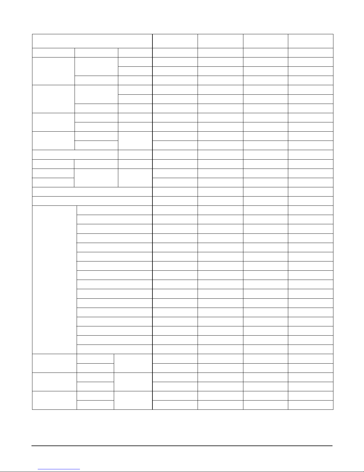
Product Specifications (Cooling & Heating)
Power Source Ø, V, Hz"
Cooling Capacity kcal/h(BTU/h)
W
Input W
Heating Capacity kcal/h(BTU/h)
W
Input W
Rated Load Amp. Cooling A
Heating A
Air Volumn Cooling(H/M/L)
CMM(m
3
/min)
Heating(H/M/L)
Refrigerant(R-22) g
Drain Hose In. Dia mm
Main Cable
No. X mm
2
Connecting Cable
Remote Control Type
Refigerant Control Type
Fuction Soft Dry
Timer
Self Diagnosis
Deice Operation
Hot Start
Zone Control(Optional)
Central Control(Optional)
Group Control(Optional wiring)
Weekly Programning
Thermistor
Drain Pump
Auto changeover(Auto Operation: CL)
Stand-by Consumption 0
Phase Control
Tele Control(Optional)
PLASMA(Optional)
Connecting Pipe Liquid Inch
Gas (mm)
Dimension Indoor mm
Outdoor (WxDxH)
Net Indoor Kg
Weight
Outdoor
1, 220-240, 50 1, 220-240, 50 1, 220-240, 50 1, 220-240, 50
4,536(18,000) 4,536(18,000) 6,048(24,000) 6,048(24,000)
5,274 5,274 7,033 7,033
2,000 2,000 2,650 2,850
4,536(18,000) - 6,048(24,000) -
5,274 - 7,033 -
1,880 - 2,400 -
10 10 12.5 13
9.5 - 11.5 -
16.5/14.5/13 16.5/14.5/13 18/16.5/14 18/16.5/14
16.5/14.5/13 - 18/16.5/14 -
1,300 1,700 1,920 1,920
22.6 22.6 22.6 22.6
3*2.5 3*2.5 3*2.5 3*2.5
6*0.75 4*0.75 6*0.75 4*0.75
L.C.D Wired L.C.D Wired L.C.D Wired L.C.D Wired
Capillary type Capillary type Capillary type Capillary type
Ye s Ye s Ye s Ye s
24 Hours On/Off 24 Hours On/Off 24 Hours On/Off 24 Hours On/Off
Ye s Ye s Ye s Ye s
Ye s - Ye s -
Ye s - Ye s -
Optional Optional Optional Optional
Optional Optional Optional Optional
Ye s Ye s Ye s Ye s
Ye s Ye s Ye s Ye s
Ye s Ye s Ye s Ye s
Ye s Ye s Ye s Ye s
Ye s Ye s Ye s Ye s
Ye s Ye s Ye s Ye s
Ye s Ye s Ye s Ye s
Optional Optional Optional Optional
Optional Optional Optional Optional
1/4(6.35) 1/4(6.35) 1/4(6.35) 1/4(6.35)
5/8(15.88) 5/8(15.88) 5/8(15.88) 5/8(15.88)
880*450*260 880*450*260 880*450*260 880*450*260
870*320*655 870*320*655 870*320*655 870*320*655
34 34 35 35
57 57 60 60
Model
LB-H1860HL/HP LB-H1860CL LB-H2460HL/HP LB-H2460CL/AL
- 7 -
Copyright ©2008 LG Electronics. Inc. All right reserved.
Only for training and service purposes
LGE Internal Use Only
Power Source Ø, V, Hz"
Cooling Capacity kcal/h(BTU/h)
W
Input W
Heating Capacity kcal/h(BTU/h)
W
Input W
Rated Load Amp. Cooling A
Heating A
Air Volumn Cooling(H/M/L)
CMM(m
3
/min)
Heating(H/M/L)
Refrigerant(R-22) g
Drain Hose In. Dia mm
Main Cable
No. X mm
2
Connecting Cable
Remote Control Type
Refigerant Control Type
Fuction Soft Dry
Timer
Self Diagnosis
Deice Operation
Hot Start
Zone Control(Optional)
Central Control(Optional)
Group Control(Optional wiring)
Weekly Programning
Thermistor
Drain Pump
Auto changeover(Auto Operation: CL)
Stand-by Consumption 0
Phase Control
Tele Control(Optional)
PLASMA(Optional)
Connecting Pipe Liquid Inch
Gas (mm)
Dimension Indoor mm
Outdoor (WxDxH)
Net Indoor Kg
Weight
Outdoor
1, 220-240, 50 1, 220-240, 50 3, 380-415, 50 3,380-415, 50
4,536(18,000) 6,048(24,000) 9,072(36,000) 9,072(36,000)
5,274 7,033 10,548 10,548
2,000 2650 4,000 4,000
4,536(18,000) 6,048(24,000) 9,072(36,000) -
5,274 7,033 10,548 -
1,880 2,400 3,300 -
10 12.5 7.2 7.2
9.5 11.5 6.3 -
16.5/14.5/13 18/16.5/14 32/29/26 32/29/26
16.5/14.5/13 18/16.5/14 32/29/26 -
1,300 1,920 1,840 1,800
22.6 22.6 22.6 22.6
3*2.5 3*2.5 4*2.5 4*2.5
6*0.75 6*0.75 5*0.75 4*0.75
L.C.D Wired L.C.D Wired L.C.D Wired L.C.D Wired
Capillary type Capillary type Capillary type Capillary type
Ye s Ye s Ye s Ye s
24 Hours On/Off 24 Hours On/Off 24 Hours On/Off 24 Hours On/Off
Ye s Ye s Ye s Ye s
Ye s - Ye s -
Ye s - Ye s -
Optional Optional Optional Optional
Optional Optional Optional Optional
Ye s Ye s Ye s Ye s
Ye s Ye s Ye s Ye s
Ye s Ye s Ye s Ye s
Ye s Ye s Ye s Ye s
Ye s Ye s Ye s Ye s
Ye s Ye s Ye s Ye s
Ye s Ye s Ye s Ye s
Optional Optional Optional Optional
Optional Optional Optional Optional
1/4(6.35) 1/4(6.35) 1/4(6.35) 1/4(6.35)
5/8(15.88) 5/8(15.88) 5/8(15.88) 5/8(15.88)
880*450*260 880*450*260 1180*450*298 1180*450*298
870*320*655 870*320*655 870*320*800 870*320*800
34 35 38 38
57 60 72 72
Model
LB-H1861BL LB-H2461BL
LB-G3680HL/HP/BS/BL
LB-G3680CL/AL
- 8 -
Copyright ©2008 LG Electronics. Inc. All right reserved.
Only for training and service purposes
LGE Internal Use Only
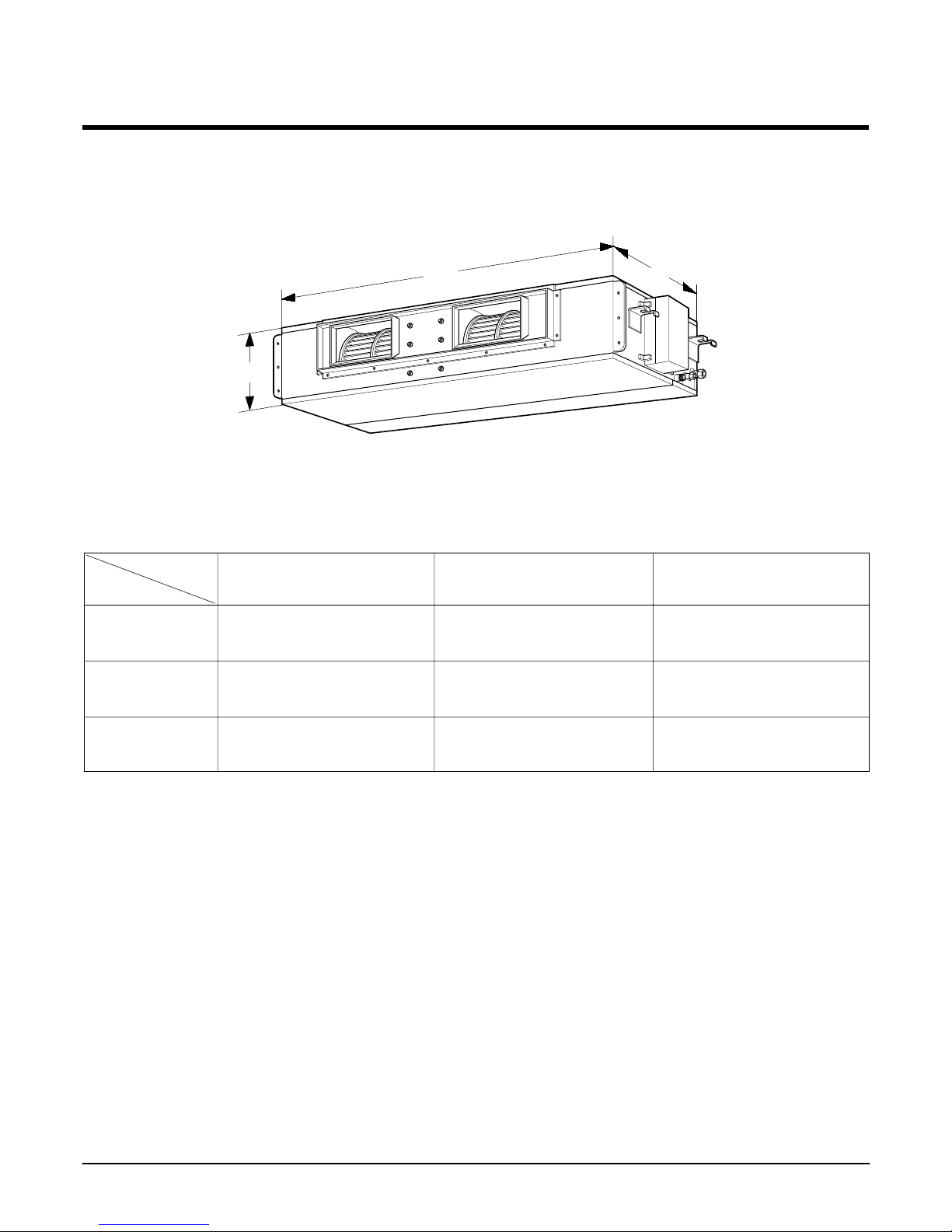
Dimensions
W
H
D
(1) Indoor Unit
MODEL
DIM
W(mm) 880 880 1180
H(mm) 260 260 298
D(mm) 450 450 450
18K 24K 36K
- 9 -
Copyright ©2008 LG Electronics. Inc. All right reserved.
Only for training and service purposes
LGE Internal Use Only
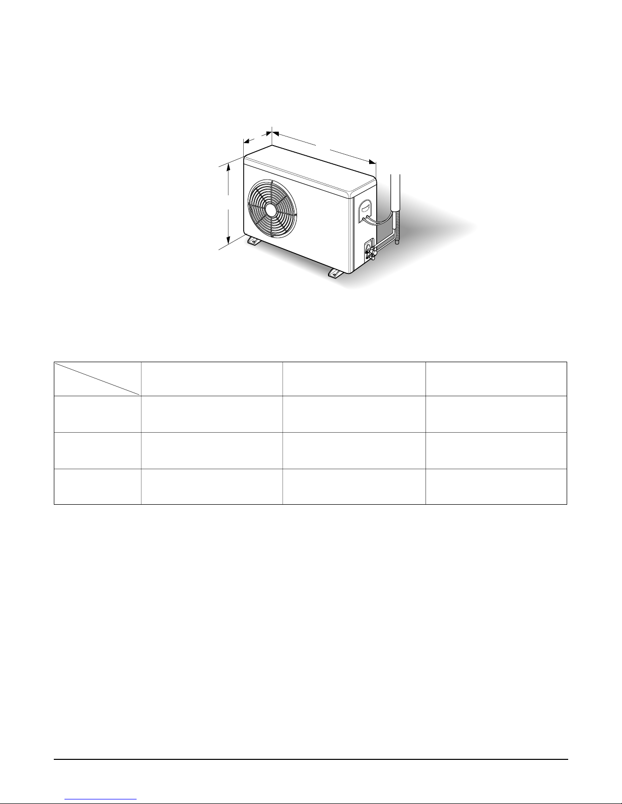
(2) Outdoor Unit
H
W
D
(18K/24K/36K)
MODEL
DIM
W(mm) 870 870 870
H(mm) 655 655 800
D(mm) 320 320 320
18K 24K 36K
- 10 -
Copyright ©2008 LG Electronics. Inc. All right reserved.
Only for training and service purposes
LGE Internal Use Only
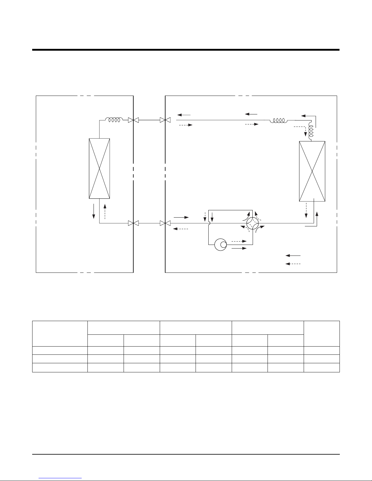
Refrigeration Cycle Diagram
•
HEAT PUMP
(LB-H1860HL/HP, LB-H1861BL, LB-H2460HL/HP/BL, LB-H2461BL,
LB-G3680HL/HP/BL/BS)
• Rated performance for refrigerant line length of: 7.5m
• If 18K Model is installed at a distance of 15m, 255g of refrigerant should be added (15-7.5)x30g=225g
INDOOR UNIT OUTDOOR UNIT
HEAT
EXCHANGER
HEAT
EXCHANGER
COMPRESSOR
GAS SIDE
LIQUID SIDE
COOLING
HEATING
REVERSING
VALVE
CAPILLARY TUBE
18K 5/8" 1/4" 7.5 50 5 30 30
24K 5/8" 1/4" 7.5 50 5 30 35
36K 5/8" 1/4" 7.5 50 5 30 45
*Additional
refrigerant
(g/m)
Pipe size(Diameter: ø) Piping length(m) Elevation(m)
MODEL
Gas Liquid Rated Max. Rated Max.
- 11 -
Copyright ©2008 LG Electronics. Inc. All right reserved.
Only for training and service purposes
LGE Internal Use Only
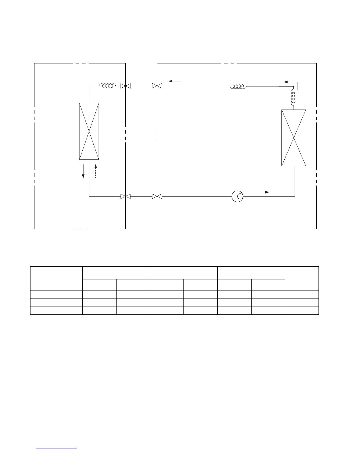
• COOLING ONLY (LB-H1860CL, LB-H2460CL/AL, LB-G3680CL/AL)
• Rated performance for refrigerant line length of: .7.5m
• If 18K Model is installed at a distance of 15m, 225g of refrigerant should be added (15-7.5)x30g=225g
INDOOR UNIT OUTDOOR UNIT
HEAT
EXCHANGER
(CONDENSER)
HEAT
EXCHANGER
(CONDENSER)
COMPRESSOR
GAS SIDE
LIQUID SIDE
CAPILLARY TUBE
LB-H1860CL 5/8" 1/4" 7.5 50 5 30 30
LB-H2460CL 5/8" 1/4" 7.5 50 5 30 35
LB-G3680CL 5/8" 1/4" 7.5 50 5 30 45
*Additional
refrigerant
(g/m)
Pipe size(Diameter: ø) Piping length(m) Elevation(m)
MODEL
Gas Liquid Rated Max. Rated Max.
- 12 -
Copyright ©2008 LG Electronics. Inc. All right reserved.
Only for training and service purposes
LGE Internal Use Only
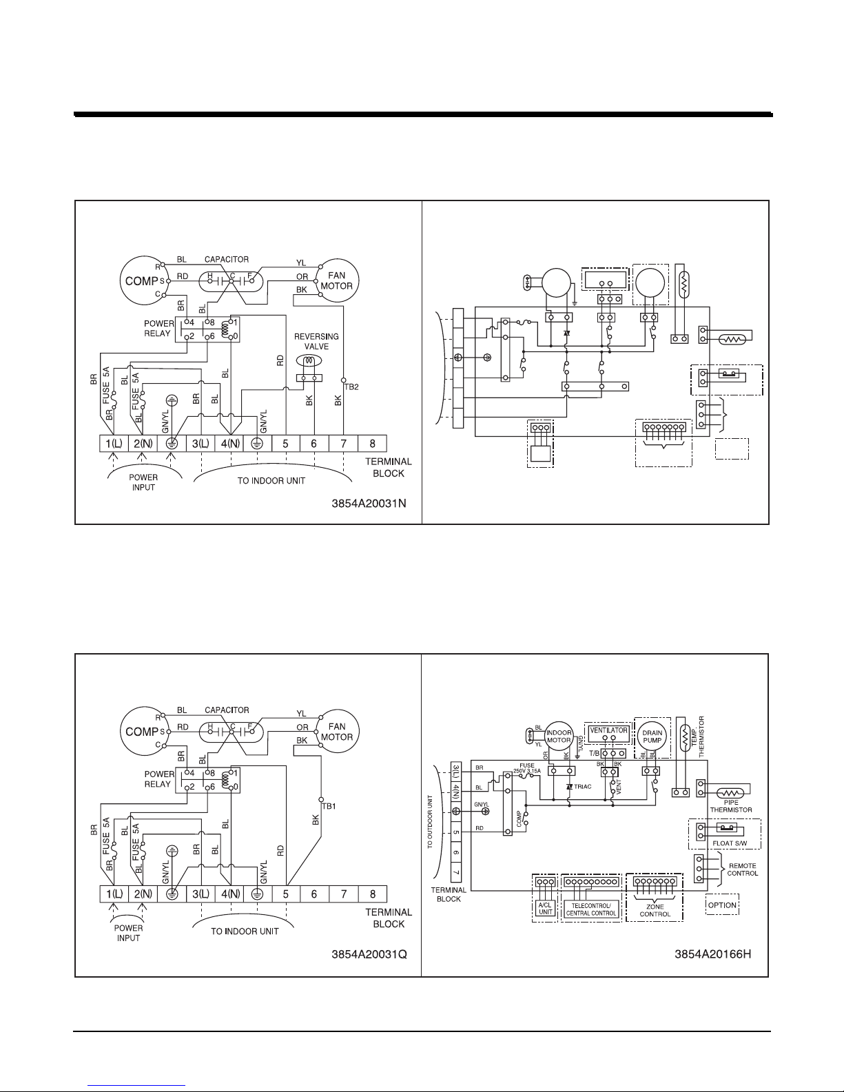
Wiring Diagram
HEAT PUMP
Model : LB-H1860HL/HP, LB-H2460HL/HP, LB-H1861BL, LB-H2461BL
COOLING ONLY
Model : LB-H1860CL, LB-H2460CL/AL
OUTDOOR WIRING DIAGRAM INDOOR WIRING DIAGRAM
3854A20166E
INDOOR
MOTOR
DRAIN
PUMP
BL
BK BK
YL
BK
RD
BL
BR
GN/YL
YL
OR
BL
BL
BK
GN/YL
COMP
4 WAY
VENT
OUT FAN
FUSE
250V 3.15A
TEMP.
THERMISTOR
PIPE
THERMISTOR
FLOAT S/W
REMOTE
CONTROL
ZONE
CONTROL
TERMINAL
BLOCK
TO OUTDOOR UNIT
3(L) 4(N) 5 6 7
TRIAC
A/CL
UNIT
OPTION
VENTILATOR
T/B
OUTDOOR WIRING DIAGRAM INDOOR WIRING DIAGRAM
- 13 -
Copyright ©2008 LG Electronics. Inc. All right reserved.
Only for training and service purposes
LGE Internal Use Only
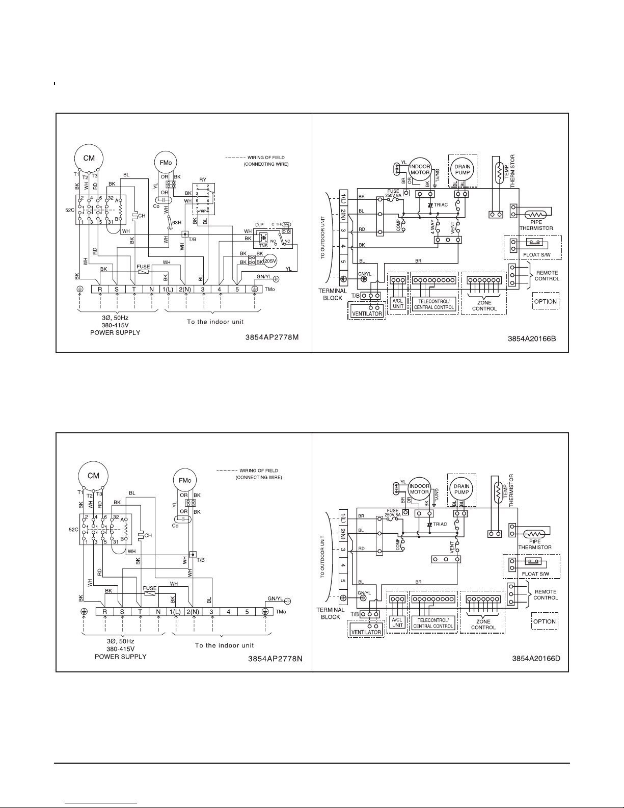
HEAT PUMP
Model : LB-G3680HL
COOLING ONLY
Model : LB-G3680CL
OUTDOOR WIRING DIAGRAM INDOOR WIRING DIAGRAM
OUTDOOR WIRING DIAGRAM INDOOR WIRING DIAGRAM
- 14 -
Copyright ©2008 LG Electronics. Inc. All right reserved.
Only for training and service purposes
LGE Internal Use Only
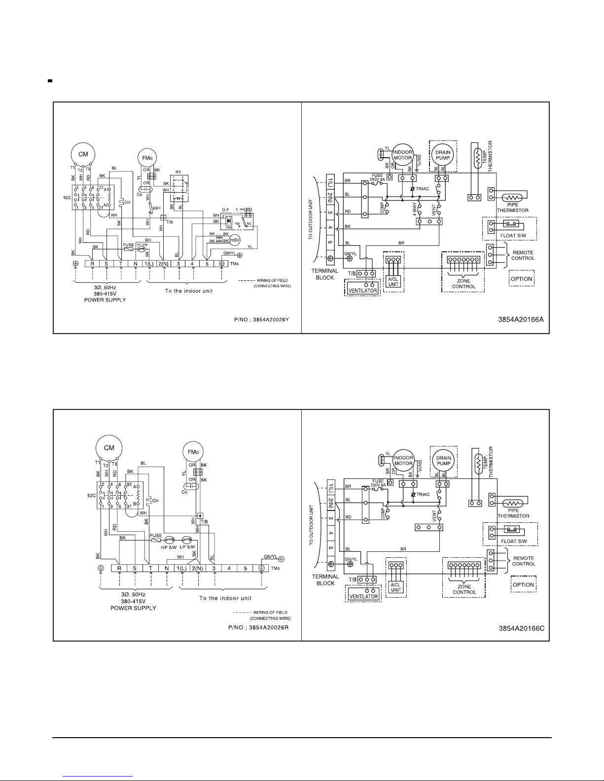
HEAT PUMP
Model : LB-G3680BS
COOLING ONLY
Model : LB-G3680CL/AL.ANW8DXT
OUTDOOR WIRING DIAGRAM INDOOR WIRING DIAGRAM
OUTDOOR WIRING DIAGRAM INDOOR WIRING DIAGRAM
- 15 -
Copyright ©2008 LG Electronics. Inc. All right reserved.
Only for training and service purposes
LGE Internal Use Only
Operation Details
(1) The function of main control
1. Time Delay safety Control
• 3min
...
The compressor is ceased for 3minutes to balance the pressure in the refrigeration cycle.
(Protection of compressor)
• 30sec
...
The 4-way valve is ceased for 30sec. to prevent the refrigerant-gas abnormal noise when the Heating
operation is OFF or switched to the other operation mode while compress is off.
While compressor is running, it takes 3~5 seconds to switch.
2. Soft-Dry Operation
• The indoor fan speed is automatically set to the low, so the shift of the indoor fan speed is impossible because of
already being set to the best speed for Dry Operation by Micom Control.
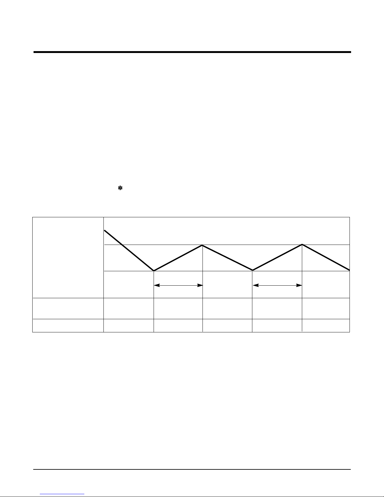
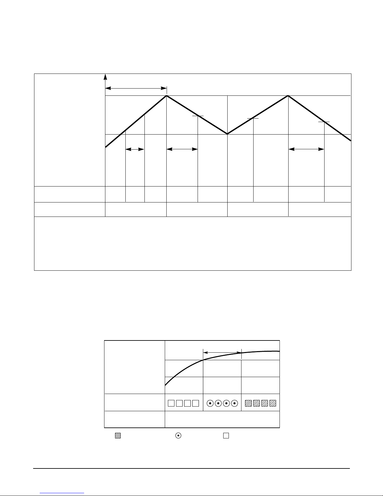
3. Cooling Mode Operation
• When selecting the Cooling( ) Mode Operation, the unit will operate according to the setting by the remote controller and the operation diagram is as following.
Intake Air temp.
SET TEMP.+0.5°C
(COMP. ON)
SET TEMP. -0.5°C
(COMP. OFF) More than More than
3 minutes 3 minutes
Selecting Selecting Selecting
fan speed fan speed fan speed
COMPRESSOR ON OFF ON OFF ON
INDOOR FAN Low Low
- 16 -
Copyright ©2008 LG Electronics. Inc. All right reserved.
Only for training and service purposes
LGE Internal Use Only
Intake Air temp.
Setting temp.+3°C
(Compressor OFF)
Setting temp.
(Compressor ON)
INDOOR FAN Low OFF Low Low OFF
COMPRESSOR ON OFF ON OFF
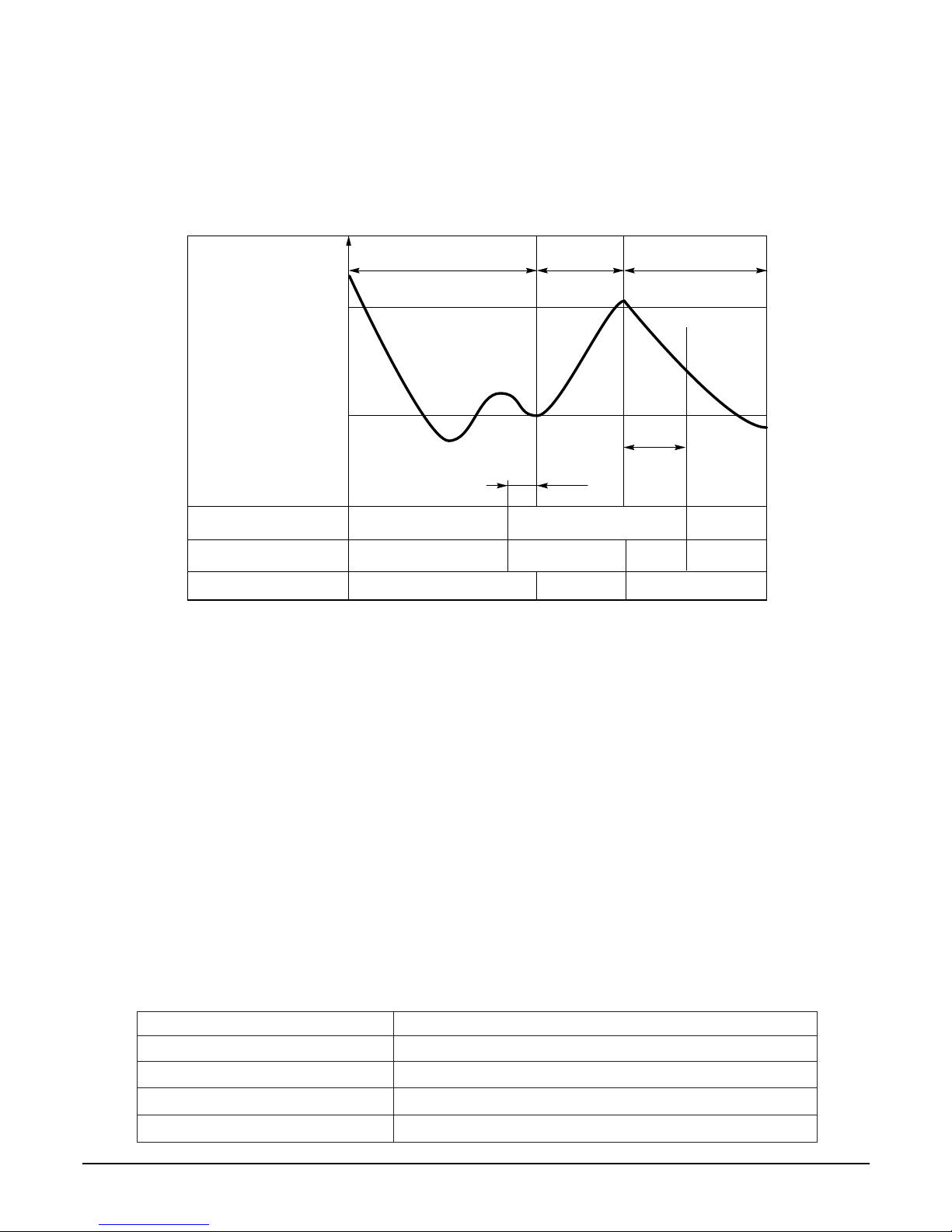
• A point; While the indoor Heat-Exchanger temperature is higher than 40°C fan operates at low speed, when
it becomes lower than 40˚C fan stops.
• B point; When the indoor Heat-Exchanger temperature is higher than 42°C, fan operates at seleted fan
speed, when it becomes lower than 39°C, the fan operates at low speed.
4. Heating Mode Operation (Except Cooling Model)
The unit will operate according to the setting by the remote controller and the operation diagram is shown as following.
Hot Start
Low
Selecting
Fan Speed
minimum 3min
Selecting fan
speed
minimum
10sec.
1min
AA
minimum
10sec.
B
5. Hot-Start Control
• The indoor fan stops until the evaporator piping temperature will be reached to 31°C.
• The operation diagram is as following.
PIPING
TEMPERATURE
1min
COMPRESSOR
INDOOR FAN
ON
28°C
: Selected Fan : Low Fan : Fan Stop
31°C
- 17 -
Copyright ©2008 LG Electronics. Inc. All right reserved.
Only for training and service purposes
LGE Internal Use Only
6. Defrost Control(36K)
• Defrost control is availavle 45 minutes later since heating mode operation started, and it will not prolong over
10 minutes.
• Defrost control is carried out when the outdoor pipe temp. falls below -6°C for more than 3 minutes after 45
minutes passed from starting of heating operation.
• Defrost ends after 10 minutes passed from starting of defrost operation or when the outdoor pipe temp. rises
over 12°C after 5 minutes passed from starting of defrost.
■ Defrost Control (New Type Defrost Control) (18K/24K)
• While in heating mode operation in order to protect the evaporator pipe of the outdoor unit from freezing, reversed to
cooling cycle to defrost the evaporator pipe of the outdoor unit.
• Defrost control is available 45 min. later since heating mode operation started, and it will not prolong over 10 min.
• Defrost control is carried out according to the following priority order while in heating mode operation.
1st priority : Defrost control is carried out according to the indoor pipe temp 60 min. later since heating mode opera-
tion started.
2nd priority : The temp differences between the indoor pipe temp and the intake air temp 25 min. later(∆T1) and 45
min. later (∆T2) since heating mode operation started are measured, then defrost control is carried out
according to the dirrerence (∆T=∆T1-∆T2)
3rd priority : Defrost control is carried out according to the temp dirrerence (E=TE1-TE2) between the indoor pipe
temperatures of 25 min later(TE1) and 45 min later (TE2) after heating mode operation started.
• When the indoor pipe temp is 41°C or above, defrost control is not carried out even if the condition is one of the
defrost conditions above.
• While in defrost control, the compressor is on and the indoor fan, the outdoor fan, and the 4 way valve are off.
7. Self-diagnosis Function
• 'CHECK' will flash in the remote controller display when a problem occurs. Then please contact your dealer.
• Correct the accident point as shown in the table below before restarting operation.
• During the normal operation 'CHECK' won't be displayed in the remote controller.
Remote controller LCD Accident Point
CH 01 Indoor room temperature thermistor error
CH 02 Indoor piping thermistor error
CH 03
Indoor main body / Remote controller unit communication error
CH 04(Optional) Water level float switch error
More than 45 minutes
of heating operation
Within
9min. 45sec.
ON OFF
ON ON
ON
ON OFF
OFF
COMPRESSOR
4-WAY VALVE
INDOOR FAN
-6°C ON
12°C OFF
The outdoor
piping Temp.
ON
More than 10 min.
running of compressor
More than 45 minutes
of heating operation
5sec.
HOT-
START
ON
- 18 -
Copyright ©2008 LG Electronics. Inc. All right reserved.
Only for training and service purposes
LGE Internal Use Only
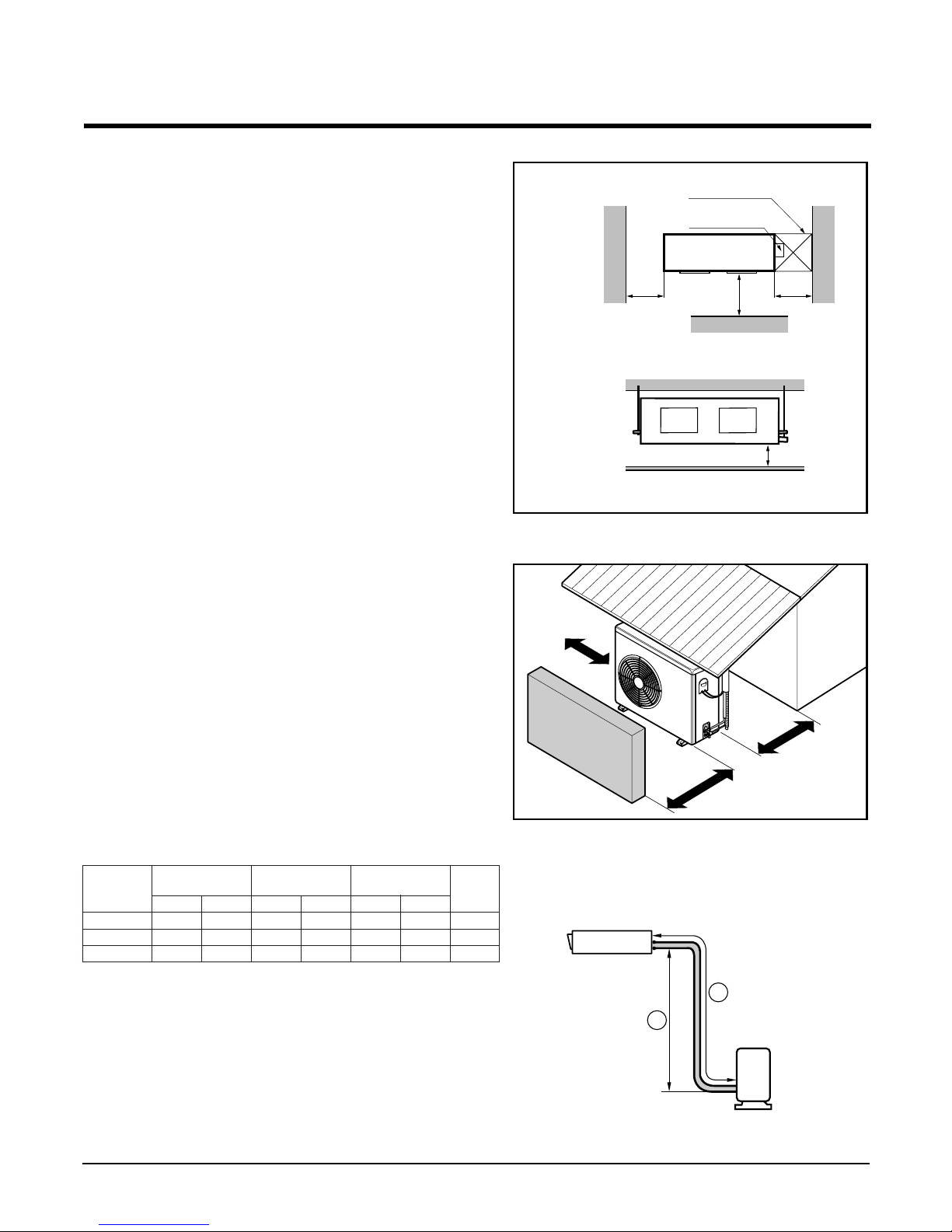
Installation of Indoor, Outdoor Unit
1. Selection of the best location
1) Indoor unit
Select location
Install the air conditioner in the location that satisfies the following conditions.
• The place shall easily bear a load exceeding four
times the indoor unit’s weight.
• The place shall be able to inspect the unit as the
figure.
• The place where the unit shall be leveled.
• The place shall allow easy water drainage.(Suit-
able dimension “H” is necessary to get a slope to
drain as figure.)
• The place shall easily connect with the outdoor
unit.
• The place where the unit is not affected by an
electrical noise.
• The place where air circulation in the room will be
good .
• There should not be any heat source or steam
near the unit
2) Outdoor unit
• If an awning is built over the unit to prevent direct
sunlight or rain exposure, be careful that heat
radiation from the condenser is not restricted.
• There should not be any animals or plants which
could be affected by hot air discharged.
• Ensure the spaces indicated by arrows from the
wall, ceiling, fence or other obstacles.
3) Piping length and the elevation
Indoor unit
Outdoor unit
B
A
More than
30cm
More than
30cm
More than
70cm
Sunroof
Fence or
obstacles
H
600600
Top view
(unit: mm)
Front view
Front
Inspection hole
(600X600)
Control box
1000
• If 18K Model is installed at a distance of 15m, 225g of
refrigerant should be added (15-7.5) x 30g = 225g
• Capacity is based on standard length and maximun
allowance length is on the basis of reliability.
• Improper refrigerant charge may result in abnormal
cycle.
18K BTU/h
30
35
45
36K BTU/h
Capacity
Gas
5/8"
5/8"
5/8"
Liquid
1/4"
1/4"
1/4"
Elevation B(m)
Length A(m)
*Additional
refrigerant
(g/m)
Pipe Size
(Diameter: Ø)
Standard
7.5
7.5
7.5
Standard
5
5
5
Max.
50
50
50
Max.
30
30
30
24K BTU/h
 Loading...