

LG L1006R, LWHD1006RY6, L1006RY6, LWHD1006R, HBLG1003R Service Manual
...
LG
Room
Air Conditioner
SERVICE MANUAL
LG
CAUTION
• BEFORE SERVICING THE UNIT, READ THE SAFETY
PRECAUTIONS IN THIS MANUAL.
• ONLY FOR AUTHORIZED SERVICE PERSONNEL.
MODEL: HBLG8003R,LB8000ER,LW8000ER,HBLG1003R,LWHD1006R,L1006R
LWHD1006RY6,L1006RY6

2 Room Air Conditioner
Air Conditioner Service Manual
TABLE OF CONTENTS
Safety Precautions..........................................................................................................................................3
Dimensions .....................................................................................................................................................5
Outside Dimensions...................................................................................................................................5
Product Specifications ..................................................................................................................................6
Installation .......................................................................................................................................................7
Select the Best Location ............................................................................................................................7
Installation Check.......................................................................................................................................7
How to Secure the Drain Pipe....................................................................................................................7
How to Install..............................................................................................................................................8
Operation ......................................................................................................................................................12
Function of Controls .................................................................................................................................12
Disassembly ..................................................................................................................................................14
Mechanical Parts......................................................................................................................................14
Air handling
Parts.....................................................................................................................................15
Elect
rical Parts .........................................................................................................................................16
Ref
rigerating Cycle...................................................................................................................................18
S
chematic Diagram.......................................................................................................................................21
Wi
ring Diagram.........................................................................................................................................21
Electronic Control D
evice.........................................................................................................................22
Components Location ..............................................................................................................................23
Trou
bleshooting Guide.................................................................................................................................24
Pipeing System ................................................................................................................
........................24
Trou
bleshooting Guide .............................................................................................................................25
Exploded Vi
ew ..............................................................................................................................................37
Replacement
Parts List ................................................................................................................................38
Electrical Parts Troubleshooting Guide......................................................................................................27
Electrical Parts ........................................................................................................................................31
Safety Precautions
Safety
Precautions
To prevent injury and property damage, follow these instructions.
Incorrect operation due to ignoring instructions might cause harm or damage, the seriousness of which is
indicated by the following symbols.
Precautions
WARNING
CAUTION
This symbol shows the possibility of death or serious injury.
This symbol indicates the possibility of injury or damage to property.
Never Do This
Always Do This
■ The following items are classified by these symbols.
WARNING
WARNING
Plug in the power plug
properly.
• Doing so may cause electric
shock or fire due to heat
generation.
Do not modify power cord
length or share the outlet
with other appliances.
• Doing so may cause electric shock or
fire due to heat generation.
Do not allow water to run
into electric parts.
• Doing so may cause failure of
machine or electric shock.
Do not use the socket if it is
loose or damaged.
Do not operate or stop the
unit by inserting or pulling
out the power plug.
• Doing so may cause electric
shock or fire due to heat
generation.
Do not operate with wet
hands or in damp
environment.
• Doing so may cause electric
shock.
Always install air leakage
breaker and a dedicated
switching board.
• Failure to install these may cause
fire or electric shock accident.
Do not open the entrance
during operation.
Do not damage or use an
unspecified power cord.
• Doing so may cause electric shock or fire.
•
If the supply cord is damaged, it must be replaced
by the manufacturer, the manufacturer's service
agent, or a similarly qualified person in order to
avoid a hazard. (Y attachment)
Always plug into a
grounded outlet.
• No grounding may cause electric
shock (See Installation Manual).
Unplug the unit if strange
sounds, odors, or smoke
comes from it.
• Such a unit may pose a risk of
fire or electric shock accident.
Keep firearms away.
• Doing so may cause fire or
electric shock.
Do not use the power cord close to heating
tools.
• Doing so may cause fire or electric shock. • Doing so may lead to an explosion or fire.
• It may cause electric shock.
Do not use the power cord near flammable gas
or combustibles such as gasoline, benzene,
thinner, etc.
Service Manual 3
Safety Precautions
WARNING
WARNING
Ventilate before operating air conditioner
when gas goes out.
• Operating the air conditioner in the presence of gas
vapors can lead to explosions and fire.
Never touch the metal parts
of the unit when removing
the filter.
• They are sharp and may cause
injury.
When cleaning the unit, first
make sure the
cord is unplugged.
•
Since the fan rotates at high speed
during operation, it may cause
injury if activated while cleaning.
is off and the
Do not clean the air
conditioner with water.
• Water may enter the unit and
degrade the insulation. It also
may cause an electric shock.
Do not put a pet or house
plant where it will be
exposed to direct air flow.
• This could injure the pet or plant. • It may cause damage of animals
• Doing so may cause failure or electric shock.
CAUTION
CAUTION
Do not disassemble or modify products
randomly.
Operate only in a well
ventilated area when using in
the presence of a stove, etc.
• An oxygen shortage may
otherwise occur.
Do not use appliance for special
purpose such as climate control for
animals or vegetables, precision
machine, or conservation of art
or vegetables or loss of property.
articles.
Stop operation in storm or
hurricanes.
• Operation with windows opened
may cause wetting of indoor and
soaking of household furniture.
Do not place obstacles
around the absorption inlet
or output.
• Doing so may cause failure of
appliance or accident.
Do not use abrasives or strong
detergent such as wax or
thinner. Always use a soft cloth.
• Otherwise, the products appearance may
be damaged due to change of product
color or scratching of its surface.
If water enters the product, turn off the the
power switch of the main body of appliance.
Contact service center after taking the powerplug out from the socket.
Hold the plug by the head
when taking it out.
• Improper handling may cause
electric shock or damage.
Ensure that an installation console of
the outdoor appliance is not damaged
due to extened use.
• If the previous air conditioner
damaged the console, there is a
risk of the new unit falling.
Do not place heavy object on the
power cord and take care so that
the cord is not pinched.
• Treating the power cord
carelessly poses a danger of fire
or electric shock.
Turn off the main power
switch when not using it for
a long time.
• Doing so can prolong the life of
the product.
Always insert filters
securely. Clean them every
two weeks.
• Operation without filters will
cause failure.
Do not drink water drained
from air conditioner.
• It contains contaminants that
would make you sick.
Do not direct airflow at room occupants only.
4 Room Air Conditioner
• This could damage your health.
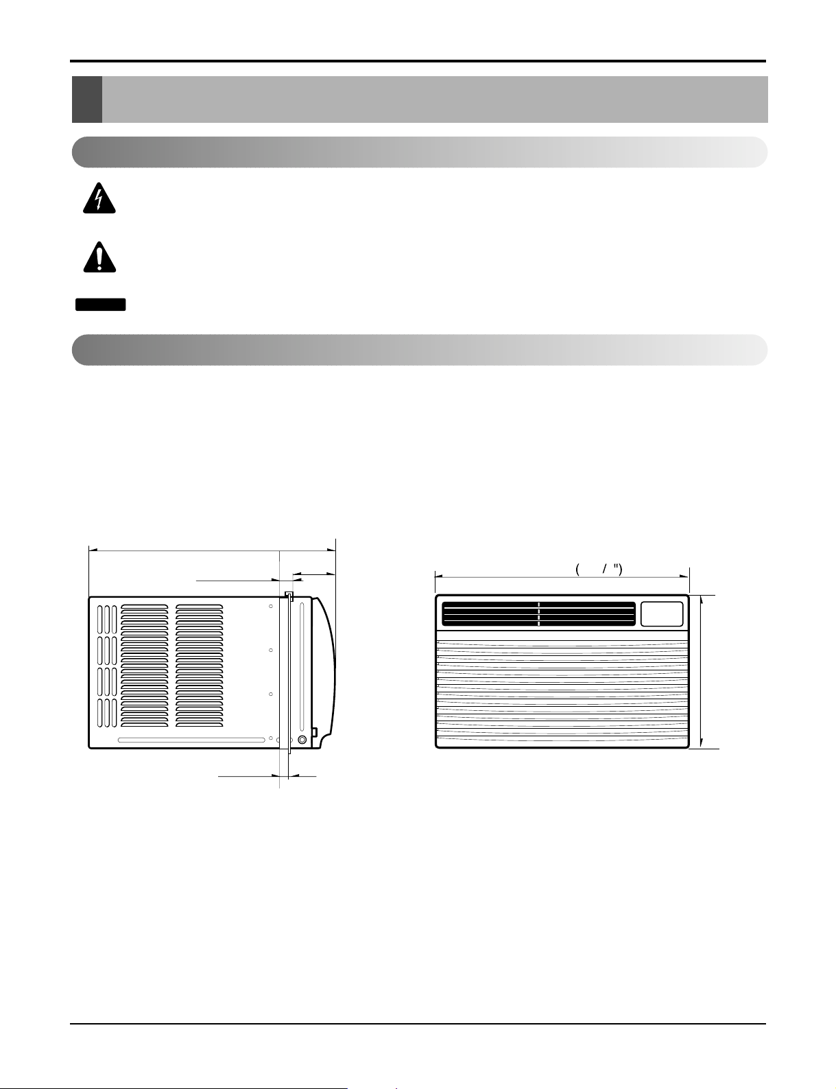
Dimensions
Dimensions
Outside Dimensions
This symbol alerts you to the risk of electric shock.
This symbol alerts you to hazards that could cause harm to the
air conditioner.
This symbol indicates special notes.
NOTICE
Symbols Used in this Manual
490(19 / )
3
8"
29(1 / )
18( / )
unit: mm(inch)
31
126.5(4 / )
5
32"
23
32"
32"
510
20
3
32
DEFROST
HEAT
COOL
FAN
DRY
FAN
ENERGY
SAVER
AIR
INDOOR DESIRED
PURYFIER
AUTO
RESTART
354(13 / ")
29
32
Service Manual 5
6 Room Air Conditioner
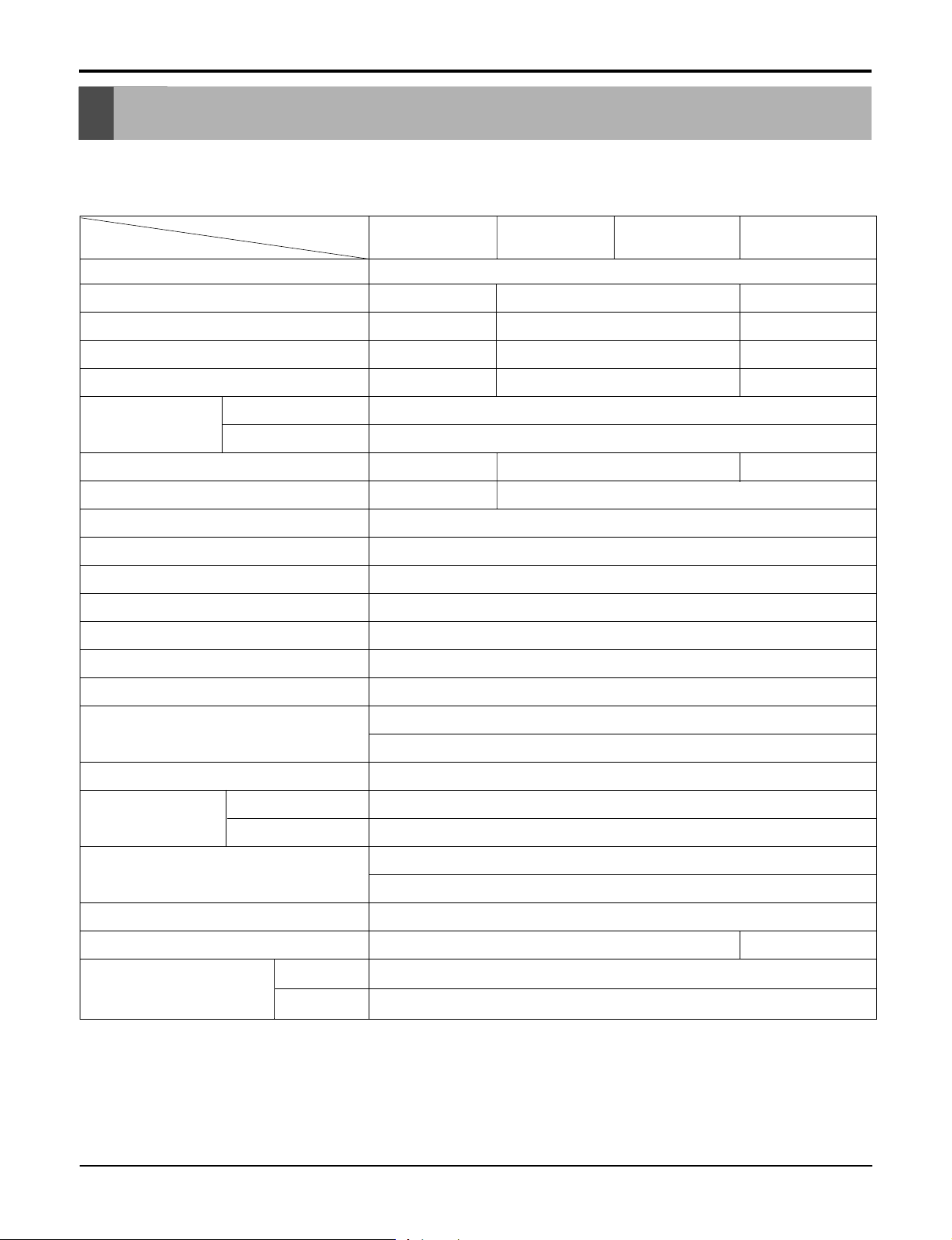
Specfications
Product SpecificationsPrProduct Specificationsoduct SpecificationsProduct Specifications
MODELS
ITEMS
POWER SUPPLY
COOLING CAPACITY (Btu/h)
INPUT (W)
RUNNING CURRENT (A)
E.E.R (BTU/W.h)
OPERATING
CONDITION
REFRIGERANT (R-22) CHARGE
EVAPORATOR
CONDENSER
FAN, INDOOR
FAN, OUTDOOR
FAN SPEEDS, FAN/COOLING
FAN MOTOR
OPERATION CONTROL
INDOOR (°C)
OUTDOOR (°C)
HBLG8003R
8,000
820
7.4
9.8
300g(10.6oz)
2 ROW 11STACKS
LB8000ER
26.7(DB)* 19.4(WB)**
35(DB)* 23.9(WB)**
2 ROW 16STACKS
PROPELLER TYPE FAN WITH SLINGER RING
REMOTE CONTROLLER
LW8000ER
1ø, 115, 60Hz
8,200 10, 000
750 1 ,020
7.0 9.2
10 . .8
9
400g(14.1oz) 420
3 ROW 11STACKS
TURBO FAN
3/3
6 POLES
HBLG1003R
LWHD1006R(Y6)
L1006R(Y6)
9
g(14.6oz)
ROOM TEMP. CONTROL
AIR DIRECTION CONTROL
CONSTRUCTION
PROTECTOR
POWER CORD
DRAIN SYSTEM
NET WEIGHT (lbs/kg)
OUTSIDE DIMENSION (inch)
(W x H x D) (mm)
* DB:Dry Bulb
**
WB:Wet Bulb
COMPRESSOR
FAN MOTOR
THERMISTOR
VERTICAL LOUVER (RIGHT & LEFT)
HORIZONTAL LOUVER (UP & DOWN)
SLIDE IN-OUT CHASSIS
OVERLOAD PROTECTOR
INTERNAL THERMAL PROTECTOR
(3 WIRE WITH GROUDING)
ATTACHMENT PLUG (CORD-CONNECTED TYPE)
DRAIN PIPE OR SPLASHED BY FAN SLINGER
62/28
203/32x 137/8x 193/
510 x 35 3 x 490
8
71 /32
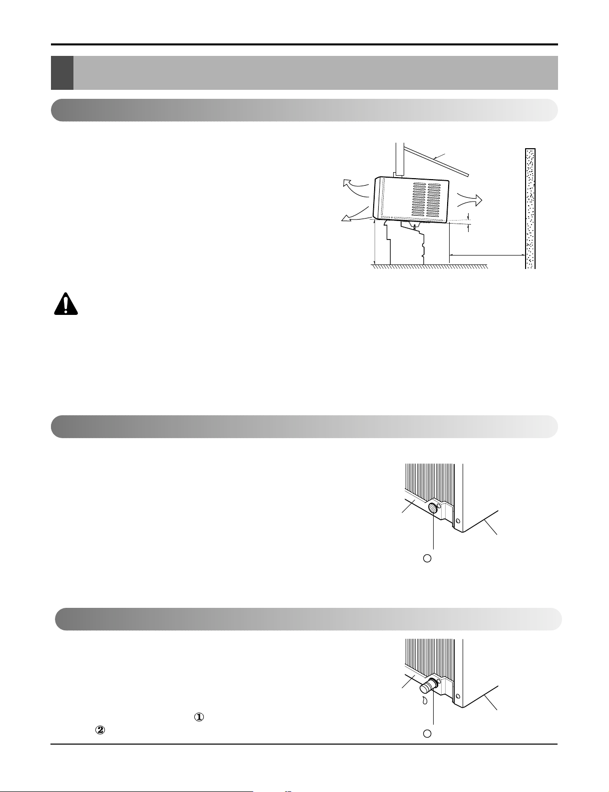
Figure 2
Figure 3
Figure 1
Installation
Installation
Select the Best Location
1.To prevent vibration and noise, make sure the unit
is installed securely and firmly.
2.Install the unit where the sunlight does not shine
directly on the unit.
3.The outside of the cabinet must extend outward for
at least 12" and there should be no obstacles, such
as a fence or wall, within 20" from the back of the
cabinet because it will prevent heat radiation of the
condenser.
Restriction of outside air will greatly reduce the
cooling efficiency of the air conditioner.
4.Install the unit a little slanted so the back is slightly
lower than the front (about1/2"). This will help force
con-densed water to the outside.
5.Install the unit from the bottom about 30"~60"
above the floor level.
The setting conditions must be checked prior to
initial starting.
The undermentioned items are especially important
checking points when the installation is finished.
1. Grounding wire (Green or Green and Yellow) is
provided in the power cord. The green wire must
be grounded.
2. Connect to a single-outlet 15A circuit.
(or 20A circuit for Electric Heater Model)
3. To avoid vibration or noise, make sure the air
conditioner is installed securely.
4 Avoid placing furniture or draperies in front of the
air inlet and outlet.
The air conditioner must be installed horizontally or
tilted slightly to the outside for proper water
drainage.
On exceptionally hot and humid days the air
conditioner may overflow condensed water.
If the air conditioner is used in hot and a high
humidity zone, exchange the HOLE RUBBER
for the DRAIN PIPE.(See figure 2, figure 3.)
Installation CheckInstallation Check
CAUTION: All side louvers of the cabinet must
remain exposed on the outdside of the structure.
COOLED AIR
30"~60"
AWNING
RADIATION
ABOUT 1/2"
FENCE
HEAT
Over 20"
How to Secure the Drain Pipe
BASE PAN
BASE PAN
1
HOLE RUBBER
2
HOLE RUBBER
BOTTOM
BOTTOM
Service ManSerSer ual vice Manvice Man 7ual ual Ser 77vice Manual 7
1. WHEN USING GASKET
2. WHEN USING INSTALLATION KITS
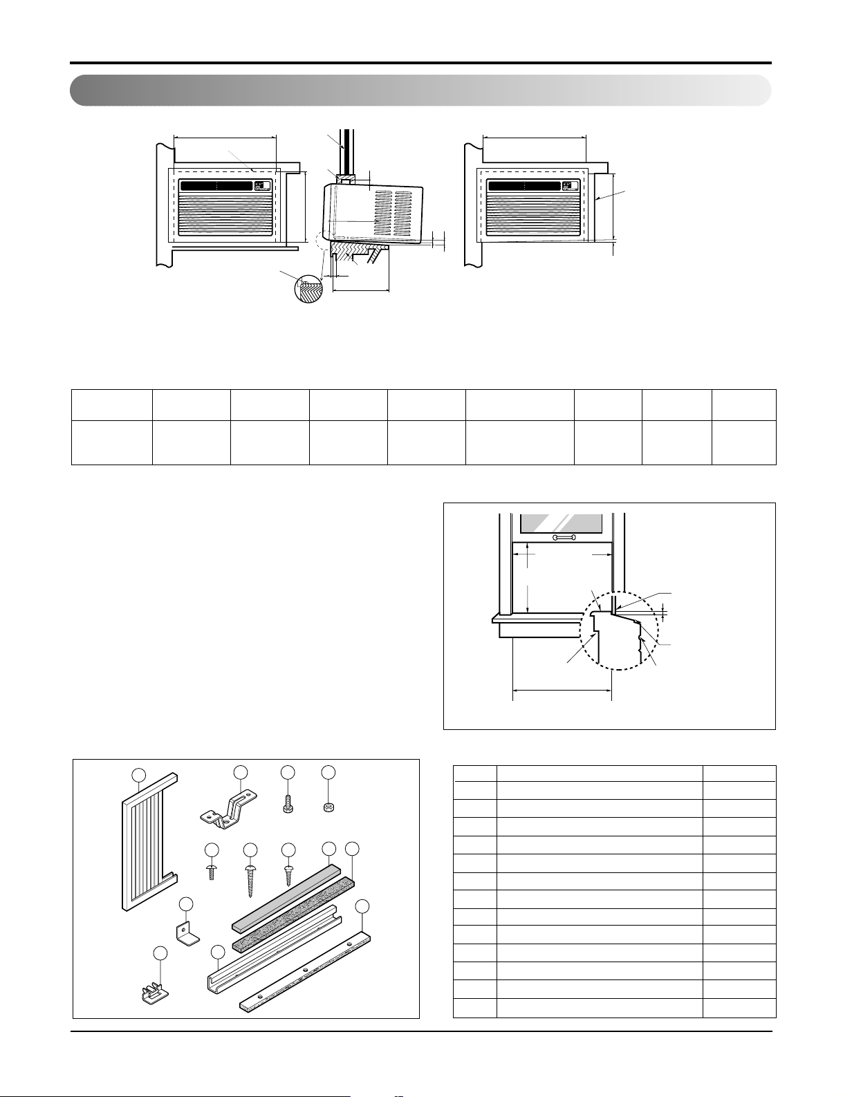
A. WINDOW REQUIREMENTS
This unit is designed for installation in
standard double hung windows with actual opening
widths from 25" to 36".
The top and bottom window sash must open
sufficiently to allow a clear vertical opening of 16"
from the bottom of the upper sash to the window
stool.
DEFROST
HEATCOOL
INDOORDESIRED
ENERGY
SAVER
AIR
PURYFIER
AUTO
RESTART
FAN
FAN
DRY
DEFROST
HEATCOOL
INDOORDESIRED
ENERGY
SAVER
AIR
PURYFIER
AUTO
RESTART
FAN
FAN
DRY
A
B
D
E
F
C
HJ
2
3
4
2
1
G
A
RIGHT SIDE
HORIZONTAL
LINE
B
1. WINDOW (WIDTH-A, HEIGHT-B)
2. GASKET
3. WALL
4. DETAILS 5.1 x 30 ROUND HEAD WOOD
SCREWS
ABCDE F HJK
535mm 366mm 250mm 30mm 0~25mm OVER 420mm 32 5~10mm 0~5mm
(211/2") (147/16") (10") (11/16") (0~1") (OVER 1617/32") (11/4") (3/16"~3/8") (0~3/16")
1
2 3 4
8 9
11
765
10
13
12
NO. NAME OF PARTS Q'TY
1 FRAME CURTAIN 2
2 SILL SUPPORT 2
3 BOLT 2
4 NUT 2
5 SCREW(TYPE A) 16
6 SCREW(TYPE B) 3
7 SCREW(TYPE C) 5
8 FOAM-STRIP 1
9 FOAM-PE 1
10 UPPER GUIDE 1
11 FOAM-PE 1
12 FRAME GUIDE 2
13
WINDOW LOCKING BRACKET
1
B. INSTALLATION KITS CONTENTS
25" to 36"
15" min
Stool
Interior wall
20
3
/32" min
(Without frame curtain)
Offset
1
/2" to 11/4"
Sill
Exterior
Installation
How to Install
8 Room Air Conditioner
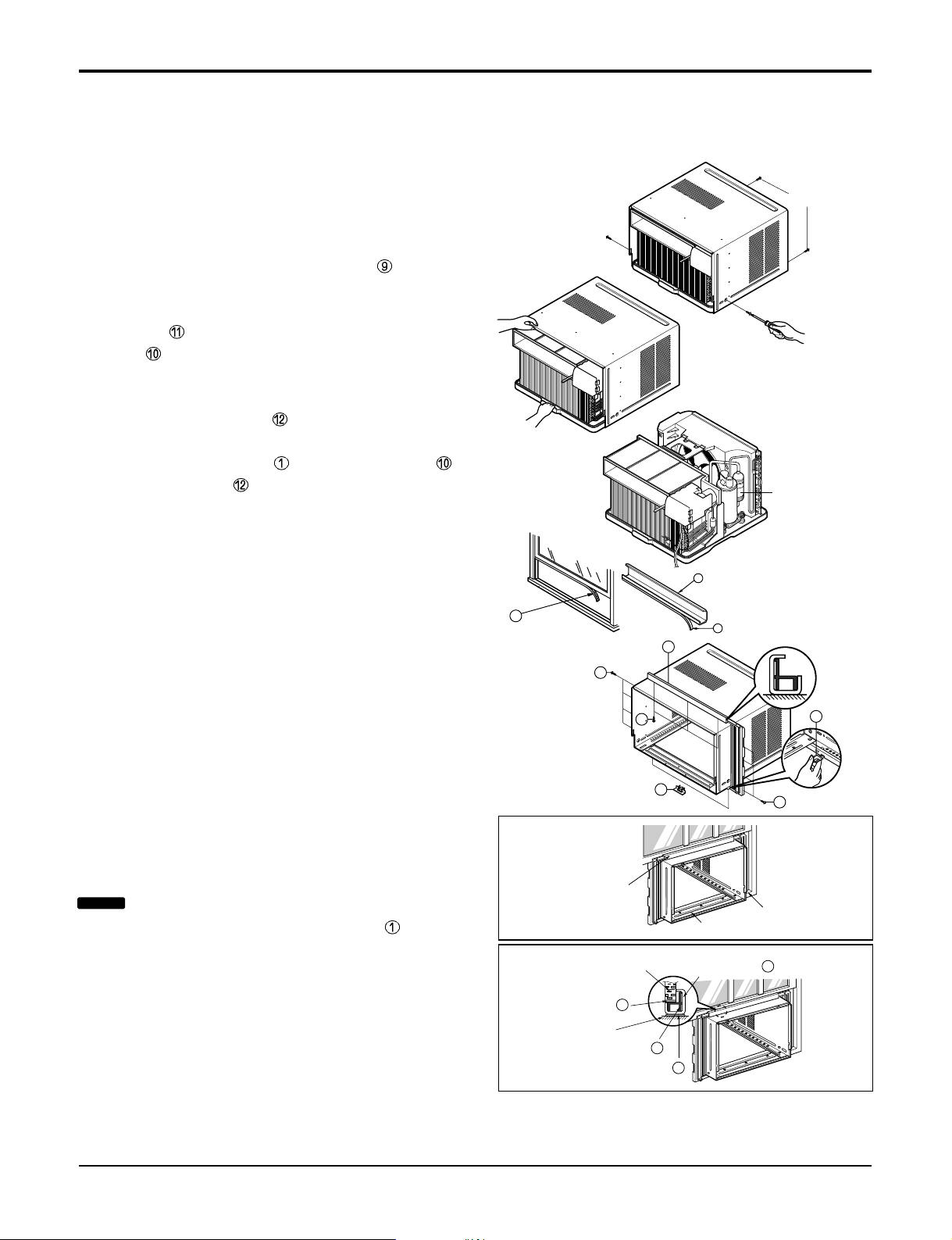
BEFORE INSTALLATION
1. Remove the screws which fasten the cabinet at
both sides and at the back.
2. Slide the unit out from the cabinet by gripping the
base pan handle and pulling forward while
bracing the cabinet.
3. Cut the window sash seal to the proper length. Peel
off the backing and attach the Foam-Pe to the
underside of the window sash.
4. Remove the backing from the top upper guide
Foam PE
and attach it to the bottom of the Upper
Guide
.
5. Attach the upper guide onto the top of the cabinet
with 3 type A screws.
6. Insert the Frame Guides into the bottom of the
cabinet.
7. Insert the Frame Curtain into the upper guide
and Frame Guides .
8. Fasten the curtains to the unit with 4 Type A screws
at the both sides.
NOW START INSTALLATION
1. Open the window. Mark a line on center of the
window stool (or desired air conditioner location).
Carefully place the cabinet on the window stool and
align the center mark on the front angle with the
center line marked in the window stool.
2. Pull the bottom window sash down behind the
upper guide until it meets.
Shipping
Screws
C
O
O
L
I
N
D
O
O
R
D
E
S
I
R
E
D
E
N
E
R
G
Y
S
A
V
E
R
A
I
R
P
U
R
Y
F
IE
R
A
U
T
O
R
E
S
T
A
R
T
F
A
N
F
A
N
D
R
Y
H
E
A
T
DEFROST
9
10
13
(Type A)
(Type A)
5
5
11
11
9
5
C
O
O
L
IN
D
OO
R
DESIRED
EN
ERG
Y
SAVER
AIR
PURYFIER
A
UTO
RE
STA
RT
F
A
N
FAN
D
R
Y
H
E
A
T
DEFRO
ST
EPS Material
Upper Guide
Window stool
Front Angle
Window Sash Upper guide
9
Frame Curtain
1
Foam-pe
10
Foam-pe
13
Cabinet
Figure 4
Figure 5
Service Manual 9
Installation
NOTICE
Do not pull the window sash down so tightly
that the movement of Frame Curtain is restricted.
INDOOR OUTDOOR
Sill Support
Nut
Bolt
2
4
3
INDOOR OUTDOOR
12
7
5
Frame Guide
About 1/2"
Screw(Type A)
Cabinet
6
2
About 1/2"
Screw(Type B)5Screw(Type A)
Sill support
Type C
Sash track
Front Angle
Screw(Type B)
6
Sill support
2
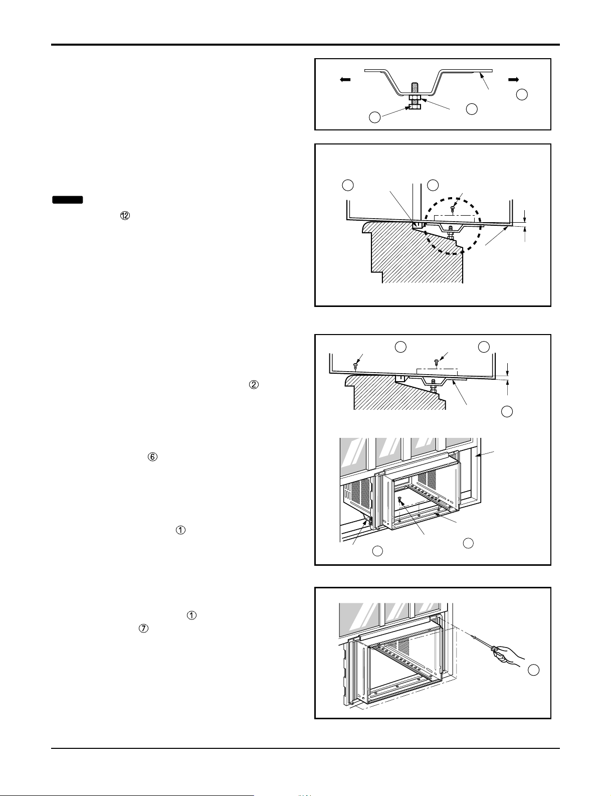
3. Loosely assemble the sill support using the parts
in
Figure
6.
4. Select the position that will place the sill
support near the outer most point on sill
(See
Figure
6)
5. Attach the sill support to the cabinet track hole in
relation to the selected position using
2 Type A screws in each support (See
Figure 7).
6. The cabinet should be installed with a very slight
tilt (about
1
/2") downward toward the outside
(See Figure 8).
Adjust the bolt and the nut of Sill Support for
balancing the cabinet.
7. Attach the cabinet to the window stool by
driving the screws (Type B: Length sixteen
millimeters and below.) through the front angle into
window stool (5/8").
8. Pull each Frame Curtain properly to each
window sash track, and repeat step 2.
9. Attach each Frame Curtain to the window sash
by using screws (Type C).
(See Figure 9)
Figure 6
Figure 7
Figure 8
Figure 9
10 Room Air Conditioner
Installation
NOTICE
Be careful when you install the cabinet (frame
guides are broken so easily).
DEFROST
HEATCOOL
INDOOR DESIRED
ENERGY
SAVER
AIR
PURYFIER
AUTO
RESTART
FAN
FAN
DRY
Screw(Type A)
Screw(Type A)
Power cord
13
8
Foam-Strip
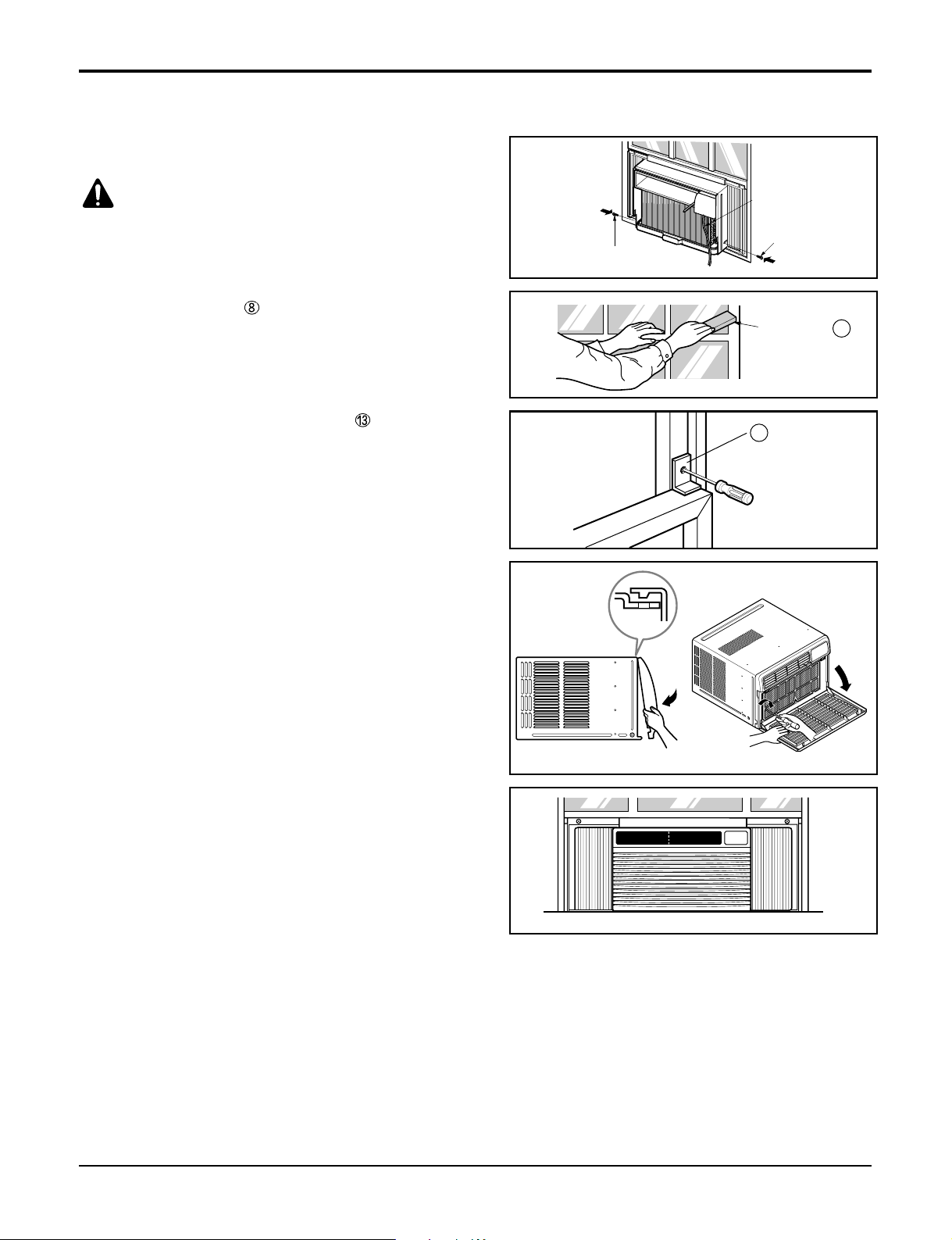
10. Slide the unit into the cabinet.(See Fig. 10)
11. Cut the Foam-Strip to the proper length and insert
between the upper and lower window sash.
(See Fig. 11)
12. Attach the window Locking Bracket with a type C
screw. (See Fig. 12)
13. Attach the front grille to the cabinet by inserting the
tabs on the grille into the tabs on the front of the
cabinet. Push the grille in until it snaps into
place.(See Fig. 13)
14. Lift the inlet grille and secure it with a type A screw
through the front grille.(See Fig. 14)
Figure 10
Figure 11
Figure 12
Figure 15
Figure 14
Figure 13
Service Manual 11
Installation
CAUTION: For security purpose, reinstall screws
(Type A) at cabinet's sides.
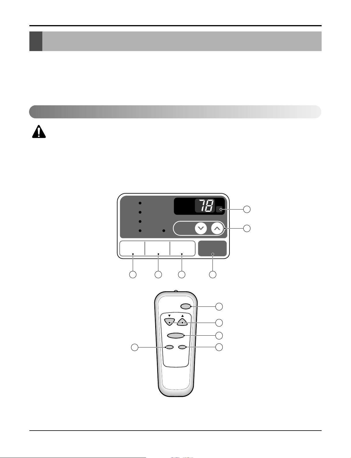
The controls look like this:
Controls
Remote Control Operations
CAUTION: The Remote Controller will not function properly if strong light strikes
the sensor window of the air conditioner or if there are obstacles between the
Remote Controller and the air conditioner.
12 Room Air Conditioner
Installation
• Designed for COOLING ONLY.
• Powerful and quiet cooling.
• Slide-in and slide-out chassis for the simple
installation and service.
• Low air-intake, top cooled-air discharge.
• Built-in adjustable Thermistor
• Washable one-touch filter
• Compact size
• Reliable and efficient rotary compressor is
equipped.
Powe r
Temp
Fan Speed
Timer Mode
1
2
3
4
5
'
F
TIMER POWERMODE
TEMP
FAN
SPEED
F1 LOW
F2 MED
F3 HIGH
Dry Timer
Fan
Energy
Saver
Cool
1
2
6
3 45
Operation
Service Manual 13
Operation
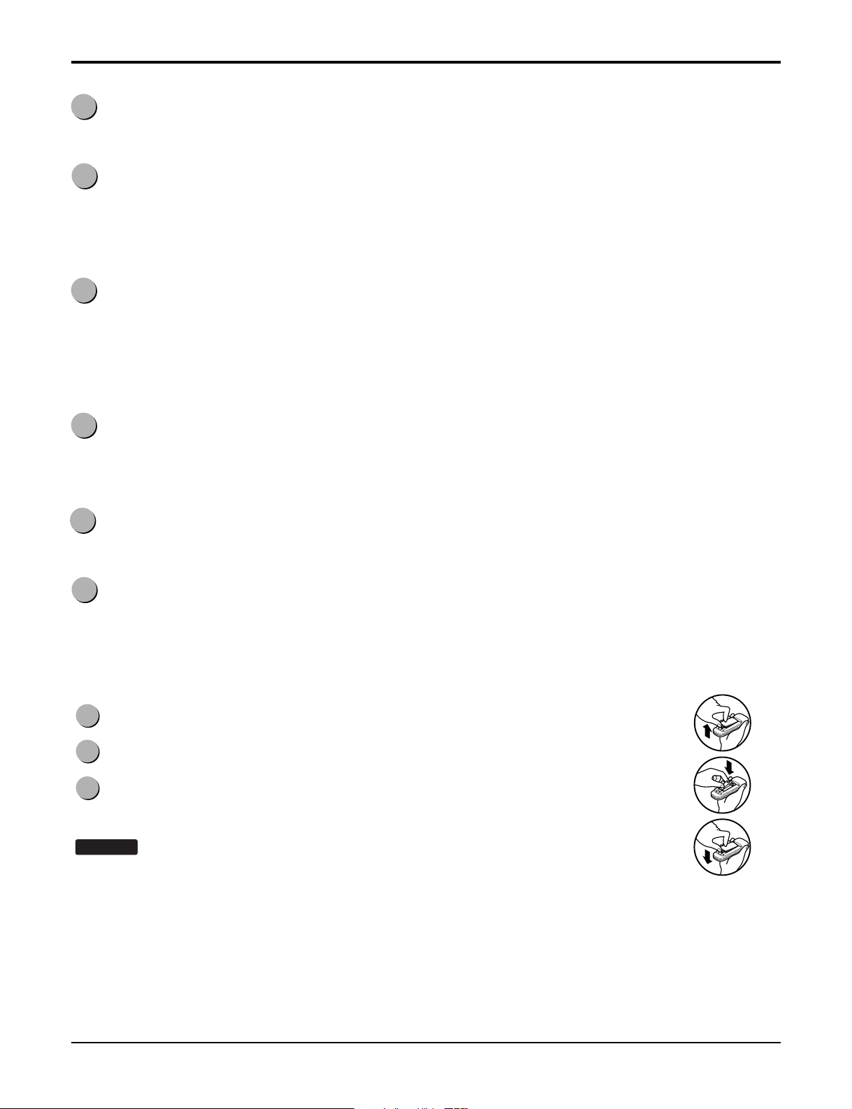
How to Insert Batteries
1
POWER
Operation starts when this button is pressed and stops when you press the button again.
2
TEMPERATURE CONTROL
The thermostat monitors room temperature to maintain the desired temperature.
The thermostat can be set between 60°F~86°F (16°C~30°C).
The unit takes an average of 30 minutes to adjust the room temperature by 1°F.
3
OPERATION MODE SELECTOR
Select cooling mode to cool the room.
Select energy saver mode for energy saving operation.
Select fan mode for basic ventilating fan operation.
Select dry mode for dry operation.
4
FAN SPEED SELECTOR
For increased power while cooling, select a higher fan speed.
3 steps: High ➔ Low ➔ Med
5
ON/OFF TIMER
The timer can be set to start and stop the unit in hourly increments (up to 12 hours).
6
REMOTE CONTROL SENSOR
1
Push out the cover on the back of the remote control with your thumb
2
Pay attention to polarity and insert two new AAA 1.5V batteries.
3
Reattach the cover.
NOTICE
• In order to prevent discharge, remove the batteries from the remote control if the air
conditioner is not going to be used for an extended period of time
Keep the remote control away from extremely hot or humid places.
To maintain optimal operation of the remote control, the remote sensor should not be
exposed to direct sunlight.
:
Do not use rechargeable batteries. Make sure that both batteries are new.
 Loading...