

LG L1710B, LB700K-GU, LB700K-GD User Manual
MENU
SOURCE
AUTO/SELECT
COLOR MONIT OR
SER VICE MANUAL
Website:http://biz.LGservice.com
E-mail:http://www.LGEservice.com/techsup.html
CAUTION
BEFORE SERVICING THE UNIT,
READ THE SAFETY PRECAUTIONS IN THIS MANUAL.
CHASSIS NO. : CL-42
F ACTORY MODEL: LB700K
MODEL: L1710B (LB700K-GU)
L1710B (LB700K-GD)
*( ) ID LABEL MODEL No.
1. LCD CHARACTERISTICS
Type : TFT SXGA LCD
Size : 17 inch
Pixel Pitch : 0.264 (H) x 0.264 (V)
Color Depth : 6-bit + FRC(16.2M)
Electrical Interface : LVDS
Surface Treatment : Anti-Glare, Polarizer Hardness
Operating Mode : Normally White
Backlight Unit : 4-CCFL (Cold Cathode
Fluorescent Lamp)
2. OPTICAL CHARACTERISTICS
2-1. Viewing Angle by Contrast Ratio
≥
10
(AU Module)
Left : -55° min., -70°(Typ) Right : +55° min., +70°(Typ)
Top :+55° min., +70°(Typ) Bottom : -55°min., -70°(Typ)
(Hydis Module)
Left : -60° min., -65°(Typ) Right : +60° min., +65°(Typ)
Top :+40° min., +45°(Typ) Bottom : -60°min., -65°(Typ)
2-2. Luminance : 200(min), 250(Typ)
2-3. Contrast Ratio : 200(min), 450(Typ)
3. SIGNAL (Refer to the Timing Chart)
3-1. Sync Signal
• Type : Separate Sync,
SOG (Sync On Green)
Composite Sync, Digital
3-2. Video Input Signal
1) Type : R, G, B Analog
2) Voltage Level : 0~0.71 V
a) Color 0, 0 : 0 Vp-p
b) Color 7, 0 : 0.467 Vp-p
c) Color 15, 0 : 0.714 Vp-p
3) Input Impedance : 75 Ω
3-3. Operating Frequency
Horizontal : 30 ~ 83kHz (Digital: 71kHz)
Vertical : 56 ~ 85Hz
4
. Max. Resolution
Analog : 1280 x 1024 / 75Hz
DVI Analog/ Digital : 1280 x 1024 / 60Hz
5. POWER SUPPLY
5-1. Power
: AC 100~240V, 50/60Hz , 1.0A
5-2. Power Consumption
6. ENVIRONMENT
6-1. Operating Temperature: 10°C~35°C (50°F~95°F)
(Ambient)
6-2. Relative Humidity : 10%~80%
(Non-condensing)
6-3. MTBF : 50,000 Hours(Min)
7. DIMENSIONS (with TILT/SWIVEL)
Width : 370 mm (14.57'')
Depth : 222.5 mm (8.76'')
Height : 421 mm (16.57'')
8. WEIGHT (with TILT/SWIVEL)
Net. Weight : 6.0 kg (13.23 lbs)
Gross Weight : 7.6 kg (16.76 lbs)
9. USB
Upstream : 1 port, Downstream : 2 port
Speed : Full-12Mbps, Low-1.5Mbps
CONTENTS
SPECIFICATIONS
- 2 -
SPECIFICATIONS ................................................... 2
PRECAUTIONS ....................................................... 4
TIMING CHART ....................................................... 5
OPERATING INSTRUCTIONS ................................ 6
WIRING DIAGRAM ................................................. 8
BLOCK DIAGRAM ................................................. 10
DESCRIPTION OF BLOCK DIAGRAM...................11
ADJUSTMENT ...................................................... 13
TROUBLESHOOTING GUIDE .............................. 14
PRINTED CIRCUIT BOARD................................... 19
EXPLODED VIEW...................................................24
REPLACEMENT PARTS LIST ...............................26
SCHEMATIC DIAGRAM......................................... 30
MODE
POWER ON (NORMAL)
STAND-BY
SUSPEND
DPMS OFF
POWER S/W OFF
H/V SYNC
ON/ON
OFF/ON
ON/OFF
OFF/OFF
-
POWER CONSUMPTION
less than 45 W
less than 3 W
less than 3 W
less than 3 W
LED COLOR
GREEN
AMBER
AMBER
AMBER
OFF
VIDEO
ACTIVE
OFF
OFF
OFF
-
less than 1 W
(@120V AC)
- 3 -
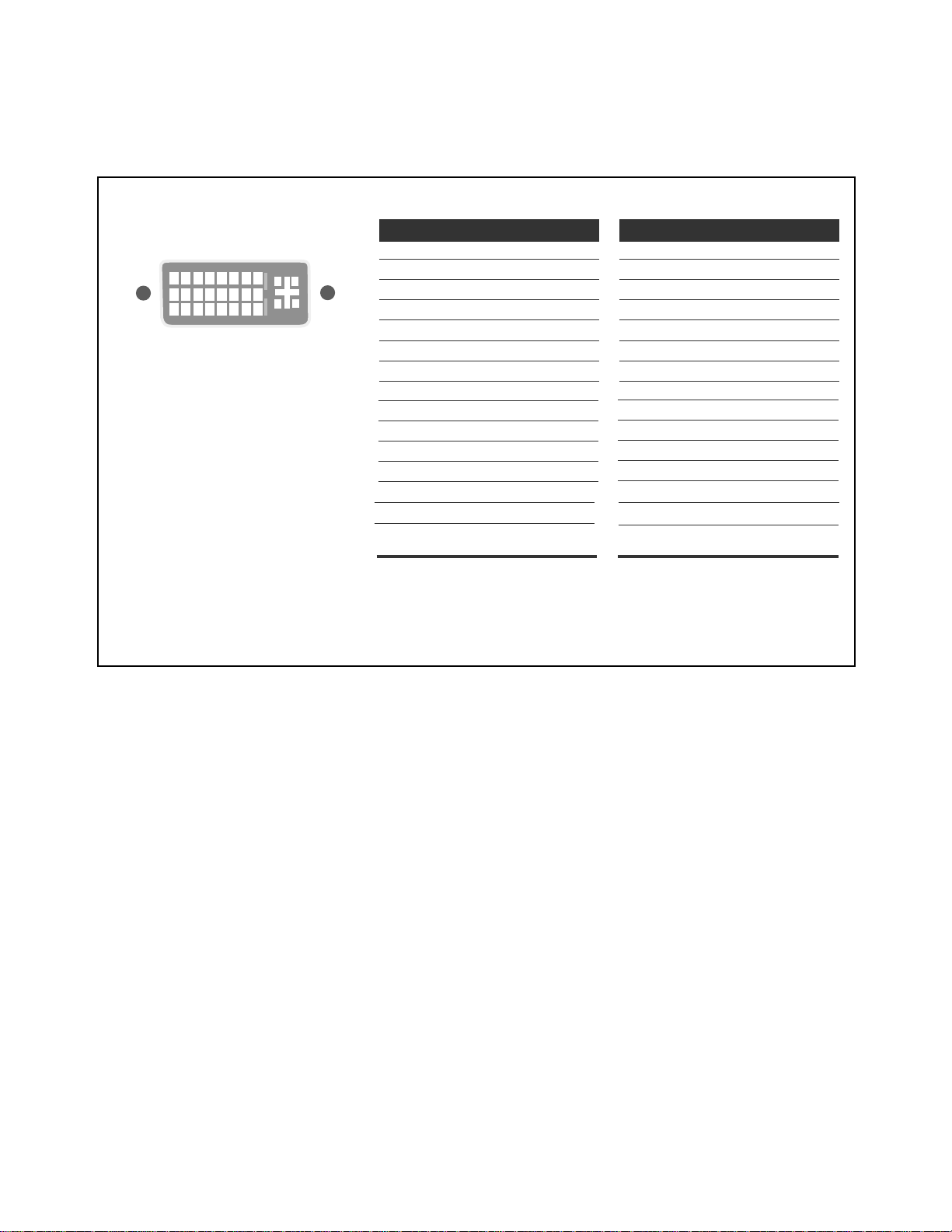
Signal Connector Pin Assignment
Pin Signal (DVI-I)
1
2
3
4
5
6
7
8
9
10
11
12
13
14
15
T. M. D. S. Data2T. M. D. S. Data2+
T. M. D. S. Data2/4 Shield
T. M. D. S. Data4T. M. D. S. Data4+
DDC Clock
DDC Data
Analog Vertical Sync.
T. M. D. S. Data1T. M. D. S. Data1+
T. M. D. S. Data1/3 Shield
T. M. D. S. Data3T. M. D. S. Data3+
+5V Power
Ground
(return for +5V,
H. Sync. and V. Sync.)
Pin Signal (DVI-I)
1
8
9
17
24
16
C1
C4
C3
C2
C5
16
17
18
19
20
21
22
23
24
C1
C2
C3
C4
C5
Hot Plug Detect
T. M. D. S. Data0T. M. D. S. Data0+
T. M. D. S. Data0/5 Shield
T. M. D. S. Data5T. M. D. S. Data5+
T. M. D. S. Clock Shield
T. M. D. S. Clock+
T. M. D. S. ClockAnalog Red
Analog Green
Analog Blue
Analog H. Sync.
Analog Ground
T. M. D. S. (Transition Minimized Differential Signaling)
• DVI-I Connector (Digital/Analog)
- 4 -
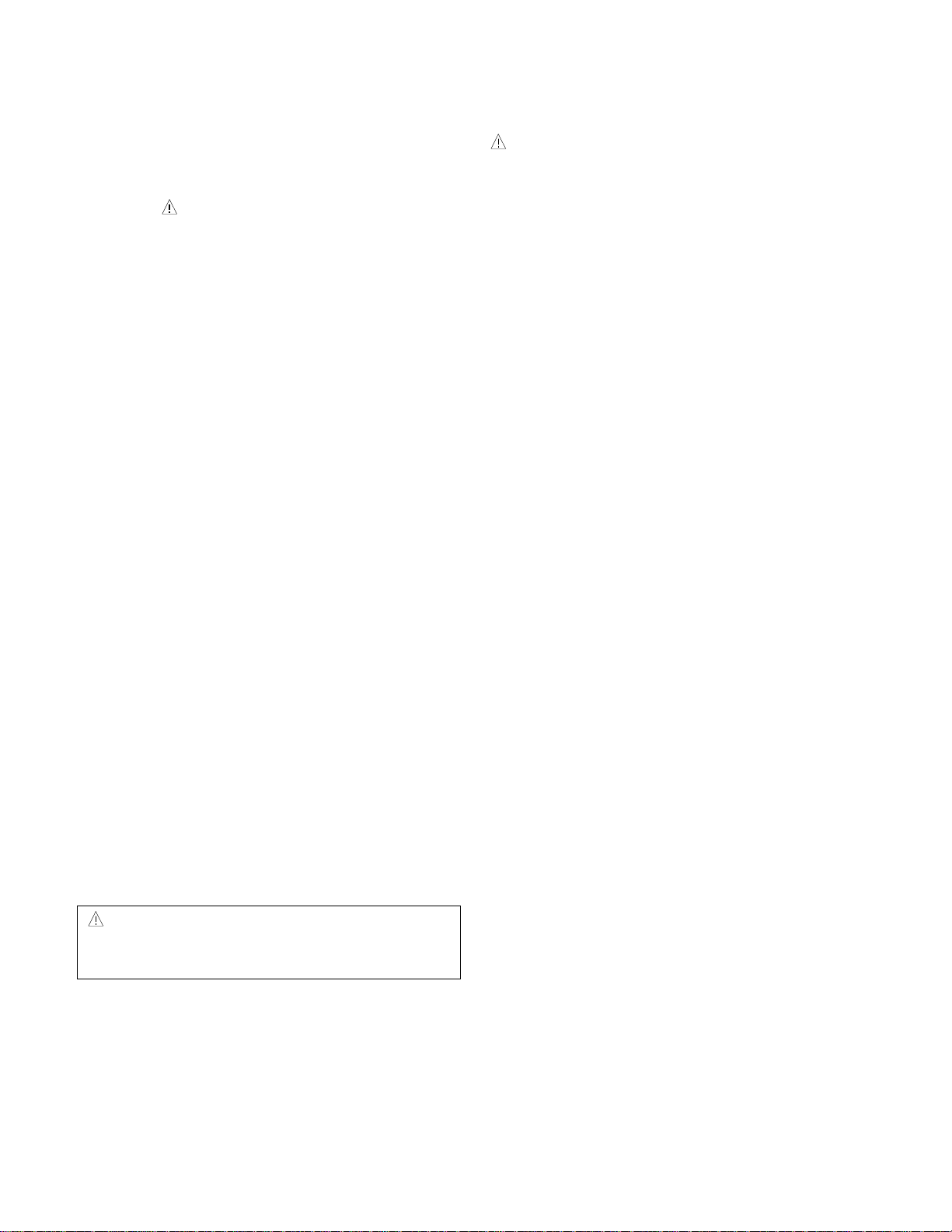
WARNING FOR THE SAFETY-RELATED COMPONENT.
• There are some special components used in LCD
monitor that are important for safety. These parts are
marked on the schematic diagram and the
replacement parts list. It is essential that these critical
parts should be replaced with the manufacturer’s
specified parts to prevent electric shock, fire or other
hazard.
• Do not modify original design without obtaining written
permission from manufacturer or you will void the
original parts and labor guarantee.
TAKE CARE DURING HANDLING THE LCD MODULE
WITH BACKLIGHT UNIT.
• Must mount the module using mounting holes arranged
in four corners.
• Do not press on the panel, edge of the frame strongly
or electric shock as this will result in damage to the
screen.
• Do not scratch or press on the panel with any sharp
objects, such as pencil or pen as this may result in
damage to the panel.
• Protect the module from the ESD as it may damage the
electronic circuit (C-MOS).
• Make certain that treatment person’s body are
grounded through wrist band.
• Do not leave the module in high temperature and in
areas of high humidity for a long time.
• The module not be exposed to the direct sunlight.
• Avoid contact with water as it may a short circuit within
the module.
• If the surface of panel become dirty, please wipe it off
with a softmaterial. (Cleaning with a dirty or rough cloth
may damage the panel.)
WARNING
BE CAREFUL ELECTRIC SHOCK !
• If you want to replace with the new backlight (CCFL) or
inverter circuit, must disconnect the AC adapter
because high voltage appears at inverter circuit about
650Vrms.
• Handle with care wires or connectors of the inverter
circuit. If the wires are pressed cause short and may
burn or take fire.
PRECAUTION
CAUTION
Please use only a plastic screwdriver to protect yourself
from shock hazard during service operation.
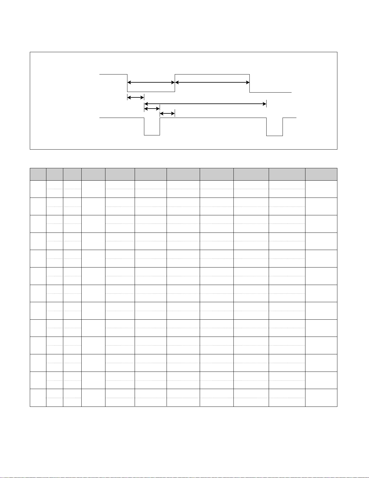
TIMING CHART
- 5 -
VIDEO
SYNC
B
D
C
F
E
A
<< Dot Clock (MHz), Horizontal Frequency (kHz), Vertical Frequency (Hz), Horizontal etc... (µs), Vertical etc... (ms) >>
H + 31.469 800 640 16 96 48
V – 70.8Hz 449 350 37 2 60
H – 31.469 840 640 16 96 48
V – 59.94 525 480 10 2 33
H – 37.5 840 640 16 64 120
V – 75 500 480 1 3 16
H – 31.468 900 720 18 108 54
V + 70.09 449 400 12 2 35
H + 37.879 1056 800 40 128 88
V + 60.317 628 600 1 4 23
H + 46.875 1056 800 16 80 160
V + 75.0 625 600 1 3 21
H+/– 49.725 1152 832 32 64 224
V+/– 74.55 667 624 1 3 39
H – 48.363 1344 1024 24 136 160
V – 60.0 806 768 3 6 29
H – 60.123 1312 1024 16 96 176
V – 75.029 800 768 1 3 28
H+/– 68.681 1456 1152 32 128 144
V+/– 75.062 915 870 3 3 39
H+/– 61.805 1504 1152 18 134 200
V+/– 65.96 937 900 2 4 31
H + 63.981 1688 1280 48 112 248
V + 60.02 1066 1024 1 3 38
H + 79.976 1688 1280 16 144 248
V + 75.035 1066 1024 1 3 38
Mode
H/V
Sort
1
2
3
4
5
6
7
8
9
10
11
12
13
25.175
28.321
25.175
31.5
40.0
49.5
57.283
65.0
78.75
100.0
92.978
108.0
135.0
640x350
70Hz
640x480
60Hz
640x480
75Hz
720x400
70Hz
800x600
60Hz
800x600
75Hz
832x624
75Hz
1024x768
60Hz
1024x768
75Hz
1152x870
75Hz
1152x900
65Hz
1280x1024
60Hz
1280x1024
75Hz
Sync
Polarity
Frequency
Dot
Clock
Total Period
(E)
Video Active Time
(A)
Sync Duration
(D)
Back Porch
(F)
Front Porch
(C)
Resolution
- 6 -
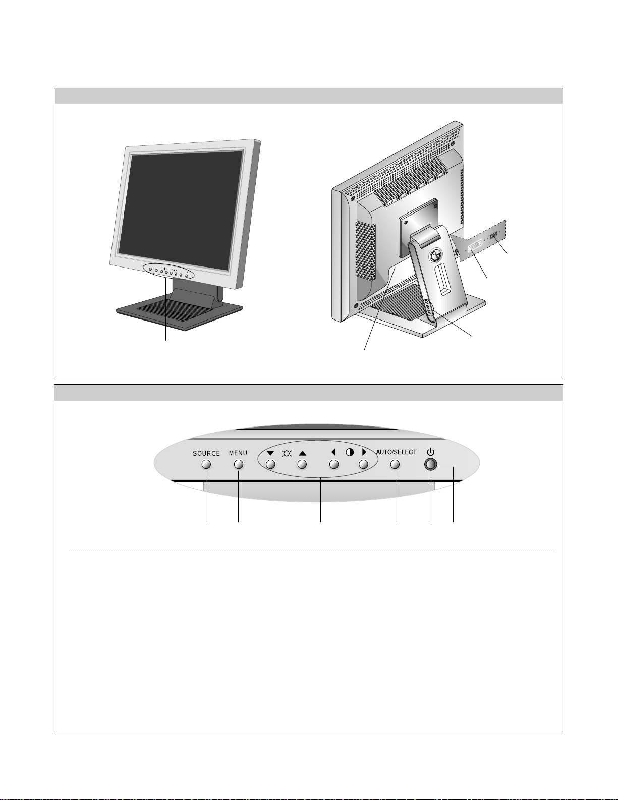
FRONT VIEW
Front Control Panel
REAR VIEW
OPERATING INSTRUCTIONS
MENU
SOURCE
AUTO/SELECT
See Front Control Panel
Power Connect
USB Port
213 46 5
1. Power ON/OFF Button
Use this button to turn the monitor on or off.
2. Power Indicator
This indicator lights up green when the monitor
operates normally. If the display is in DPM(Energy
Saving)mode, this indicator color change to amber.
3. MENU Button
Use these buttons to enter or exit the On Screen Display.
4.
▼▲◀▶
Button
Use these buttons to choose or adjust items in the On
Screen Display.
5. AUTO/SELECT Button
Use this button to enter a selection in the On Screen Display.
Use this button to scanning auto adjust.
6. SOURCE Button
Use this button to make Dsub or DVI connector active.
This feature is used when two computers are connected to
the monitor. The default setting is Dsub.
DVI Connect
D-Sub Signal
Connect
- 7 -
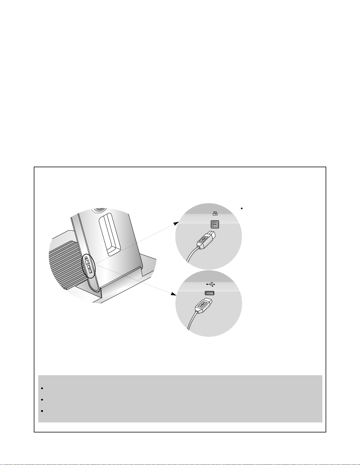
Making use of USB (Universal Serial Bus)*
USB (Universal Serial Bus) is an innovation in connecting your different desktop peripherals conveniently to your computer.
By using the USB, you will be able to connect your mouse, keyboard, and other to your monitor instead of having to
connect them to your computer. This will give you greater flexibility in setting up your system. USB allows you to connect
chain up to 120 devices on a single USB port, and you can “hot” plug (attach them while the computer is running) or unplug
them while maintaining Plug and Plug auto detection and configuration. This monitor has an integrated BUS-powered USB
hub, allowing up to 2 other USB devices to be attached it.
USB connection
1. Connect the upstream port of the Display to the downstream port of the USB compliant PC or another hub using the
USB cable. (Computer must have a USB port)
2. Connect the USB compliant peripherals to the downstream ports of the monitor.
NOTE
To activate the USB hub function, the monitor must be connected to a USB compliant PC(OS) or another hub with the USB
cable(enclosed).
When connecting the USB cable, check that the shape of the connector at the cable side matches the shape at the connecting
side.
Even if the monitor is in a power saving mode, USB compliant devices will function when they are connected the USB ports(both
the upstream and downstream) of the monitor.
USB downstream Port
connect the cables from USB
compliant peripherals-such as
keyboard, mouse, etc
This is a simplified representation
of rear view.
To USB downstream port
of the USB compliant PC or
another hub cable
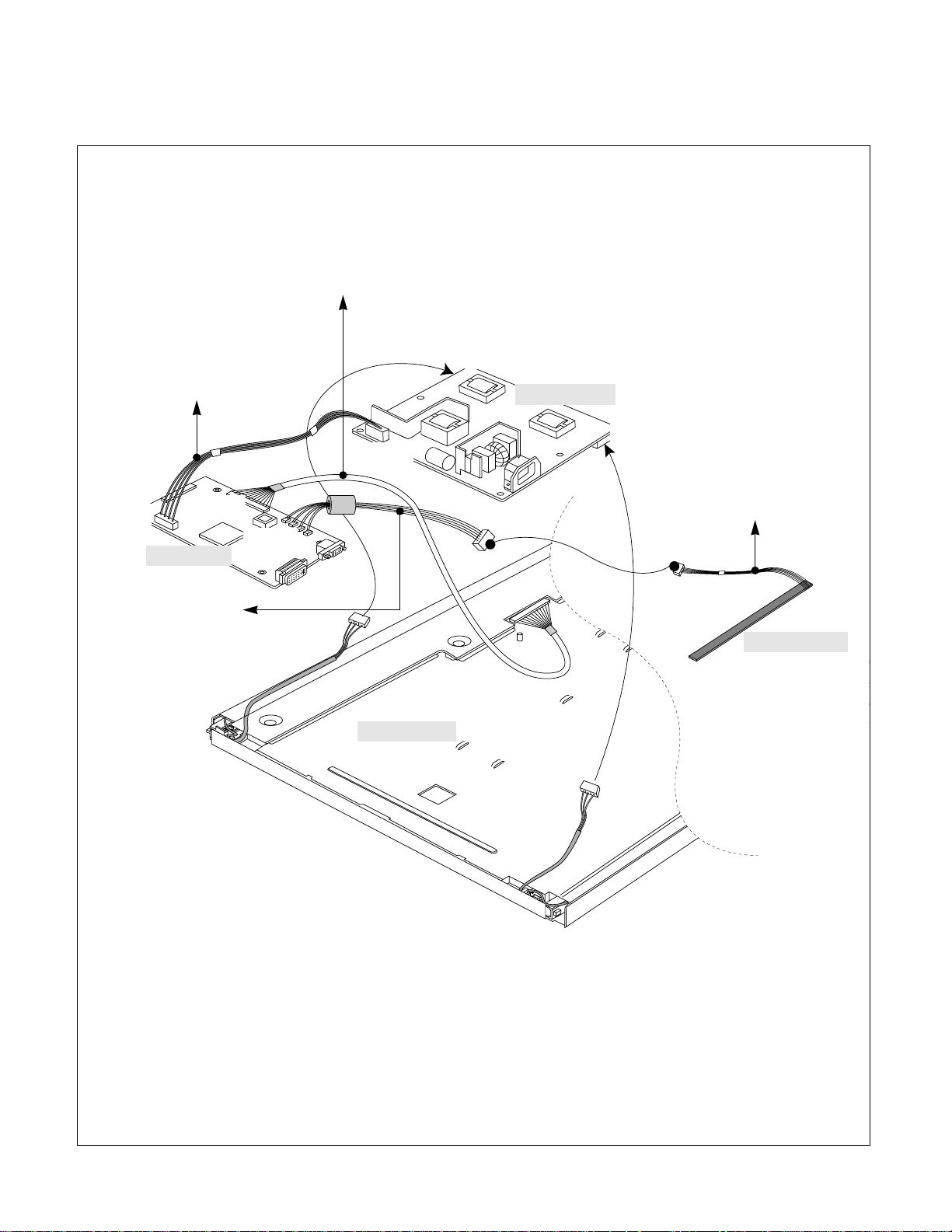
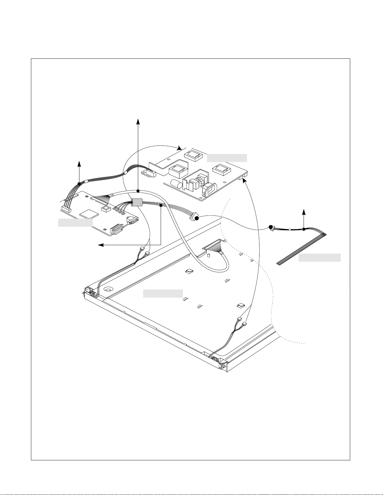
Power Board
Main Board
LCD Module
Control Board
CN1
CN3
J702
J705
J710
CN2
J1
- 8 -
WIRING DIAGRAM
(AU Module)
Connector Ass’y P/N:
6631T12002L
Connector Ass’y P/N:
6631T25008V
Connector Ass’y P/N:
6631T11012Q
Connector Ass’y P/N:
6631T12002M
- 9 -
Power Board
Main Board
LCD Module
Control Board
CN1
J702
J705
J710
CN3
CN2
CN4
CN5
J1
WIRING DIAGRAM
(Hydis Module)
Connector Ass’y P/N:
6631T12002L
Connector Ass’y P/N:
6631T25008V
Connector Ass’y P/N:
6631T11012Q
Connector Ass’y P/N:
6631T12002M
- 10 -
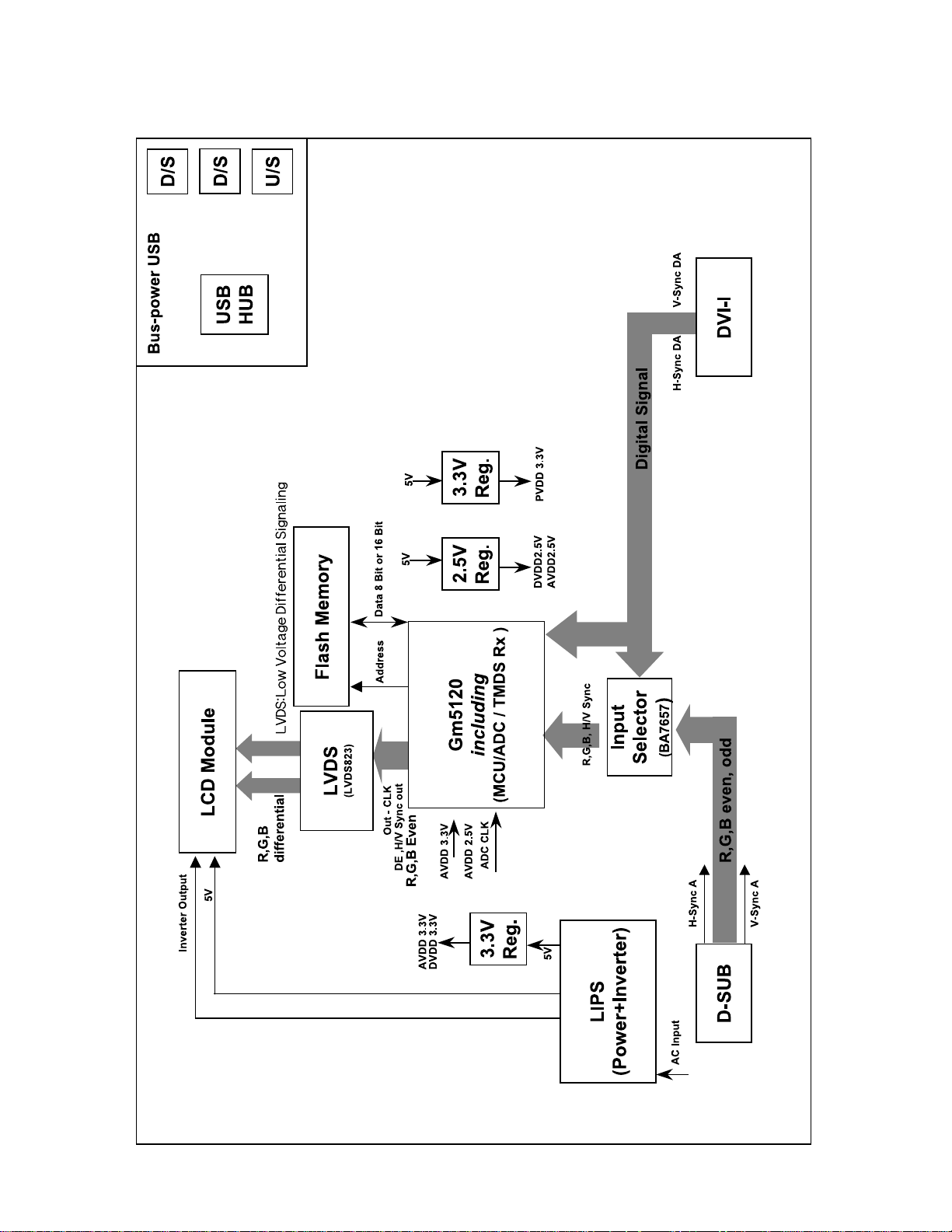
BLOCK DIAGRAM

- 11 -
DESCRIPTION OF BLOCK DIAGRAM
1. Input signal switching part.
There are two inputs which are analog and digital analog input.
They come from each 15 pin D-Sub and 24 pin DVI-I connector.
2. Video Controller Part.
This part amplifies the level of video signal for the digital conversion and converts from the analog video signal to the
digital video signal using a pixelclock.
The pixel clock for each mode is generated by the PLL.
The range of the pixel clock is from 25MHz to 135MHz.
This part consists of the Scaler, Flash-ROM IC which stores program data,Reset IC.
The Scaler gets the video signal converted analog to digital, interpolates input to1280 X 1024 resolution signal and
outputs R, G, B signal to transmitter.
The controlled data of each modes and user setting is stored in EEPROM
Especially Micom/pre-amp / ADC / Video controller are merged to one chip ‘Gm5120’ by Genesis. .
3. Display Data Transmitter Part.
This part transmit digital signal from the Scaler to the receiver of module.
4. Power Part.
This part consists of the one 5V, two 3.3V and one 2.5 regulators to convert power which is provided 12V, 5V in
LIPS Board.
5V is provided for LCD Panel.
Also, 5V is converted 3.3V and 2.5V by regulator. Converted power is provided for IC in the main board.
- 12 -
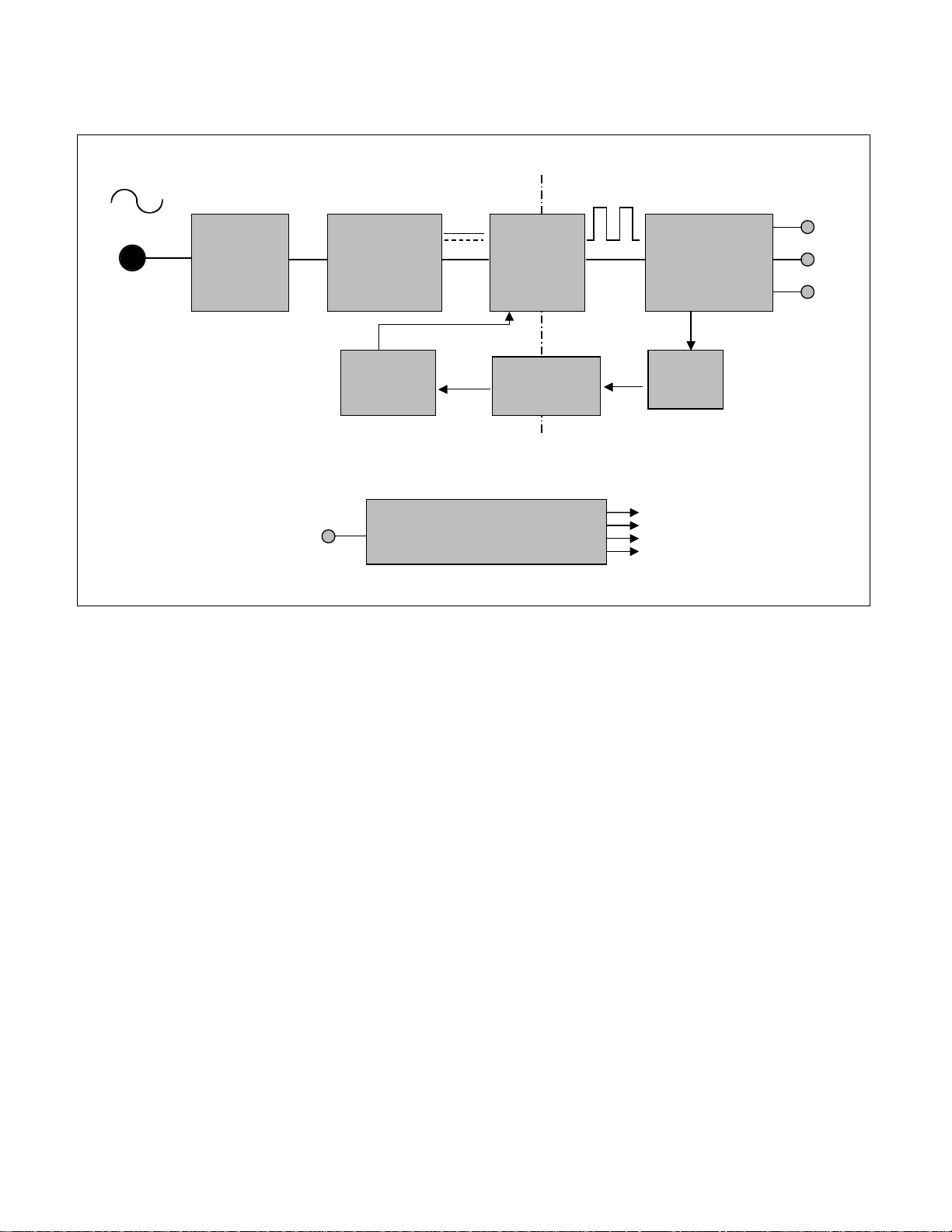
EMI
COMPONENTS
LINE
100 ~ 240V
INPUT RECTIFIER
AND FILTER
ENERGY
TRANSFER
OUTPUT RECTIFIER
AND FILTER
12V
5V
GND
SIGNAL
COLLENTI
ON
PHOTO-
COUPLER
ISOLATION
PWM
CONTROL
CIRCUIT
HVDC
100KHz
PRIMARY SECONDARY
50 ~ 60Hz
INVERTER CIRCUIT
12V
High Voltage output
Operation description_LIPS
LIPS Board Block Diagram
1. EMI components.
This part contains of EMI components to comply with global marketing EMI standards like FCC, VCCI CISPR, the
circuit included a line-filter, across line capacitor and of course the primary protection fuse.
2. Input rectifier and filter.
This part function is for transfer the input AC voltage to a DC voltage through a bridge rectifier and a bulk capacitor.
3. Energy Transfer.
This part function is transfer the primary energy to secondary through a power transformer.
4. Output rectifier and filter.
This part function is to make a pulse width modulation control and to provide the driver signal to power switch, to
adjust the duty cycle during different AC input and output loading condition to achive the dc output stablize, and also
the over power protection is also monitor by this part.
5. Photo-Coupler isolation.
This part function is to feed back the dc output changing status through a photo transistor to primary controller to
achieve the stabilized dc output voltage.
6. Signal collection.
This part function is to collect the any change from the dc output and feed back to the primary through photo
transistor.
7. Inverter
The inverter converts from DC12V to AC 700V and operate back-light lamp of module.
- 13 -
ADJUSTMENT
All adjustment are thoroughly checked and corrected
when the monitor leaves the factory, but sometimes
several minor adjustment may be required.
Adjustment should be following procedure and after
warming up for a minimum of 10 minutes.
• Alignment appliances and tools.
- IBM compatible PC
- Programmable Signal Generator.
(eg. VG-819 made by Astrodesign Co.)
- E(E)PROM with each mode data saved.
1. Adjustment Start
1) Display any pattern at any Mode.
2) Run alignment program for LB700K on the IBM
compatible PC.
3) Select EEPROM → Init → Initialize command and
Enter.
4) This will make all data to default state.
5) Select COLOR→ PRESET START command
and Enter.
2. Adjustment for White Balance
1) Display Black pattern at SXGA/60Hz.
2) Select COLOR → BIAS CALIBRATION command
and Enter.
3) No attempt to manually adjust, BIAS data is automatically adjusted and saved to the EEPROM.
4) Display Full White pattern at SXGA/60Hz.
5) Select GAIN CALIBRATION command and Enter.
6) 6500K and 9300K are automatically adjusted and
saved to the EEPROM.
7) Select COLOR → PRESET END command and
Enter.
3. Adjustment for EDID
1) Use this procedure only when there is some
probelm on EDID data.
2) Connect the D-sub cable.
3) Select EDID → Write EDID[A0] command and
Enter.
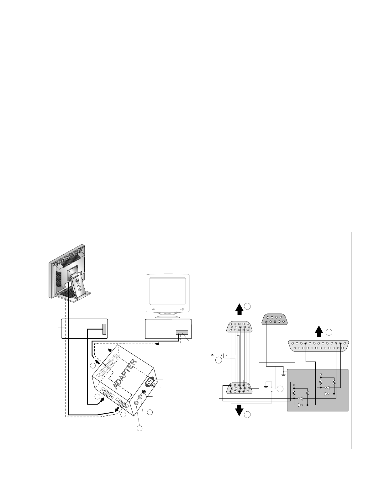
220
IBM
Compatible PC
Video Signal
Generator
PARALLEL PORT
Power inlet (required)
Power LED
ST Switch
Power Select Switch
(110V/220V)
Control Line
Not used
RS232C
PARALLEL
V-SYNC
POWER
ST
VGS
MONITOR
E
E
V-Sync On/Off Switch
(Switch must be ON.)
F
F
A
A
B
B
C
C
15
10
5
5
69
1
1
1
14
13
25
6
5V
5V
5V
4.7K
4.7K
4.7K
74LS06
74LS06
OFF ON
OFF
ON
11
Figure 1. Cable Connection
 Loading...