

LG LW1200ERY3, LW1200PRY3, LW1000PRY3, LW120CS, LW100CS Service Manual
...
LG
Room
Air Conditioner
SERVICE MANUAL
LG
MODEL: LW1200PR
LW1200ER
LW1000PR
LW1000ER
LW1004ER
LWL1210WAL
LWL1230WAL
WM-1231
LW1000ERY3
LB1000ER
LB1200ER
LW100CS
LW120CS
LW1000PRY3
LW1200PRY3
LW1200ERY3
CAUTION
website http://www.lgservice.com
• BEFORE SERVICING THE UNIT, READ THE SAFETY
PRECAUTIONS IN THIS MANUAL.
• ONLY FOR AUTHORIZED SERVICE PERSONNEL.

2 Room Air Conditioner
Air Conditioner Service Manual
TABLE OF CONTENTS
Safety Precautions..........................................................................................................................................3
Dimensions .....................................................................................................................................................5
Outside Dimensions...................................................................................................................................5
Product Specifications ..................................................................................................................................6
Installation.......................................................................................................................................................7
Select the Best Location ............................................................................................................................7
Installation Check.......................................................................................................................................7
How to Secure the Drain Pipe....................................................................................................................7
How to Install..............................................................................................................................................8
Suggested Tool Requirements...................................................................................................................9
Operation ......................................................................................................................................................12
Function of Controls.................................................................................................................................12
Disassembly..................................................................................................................................................15
Mechanical Parts......................................................................................................................................15
Air handling Parts.....................................................................................................................................16
Electrical Parts .........................................................................................................................................17
Refrigerating Cycle...................................................................................................................................19
Schematic Diagram.......................................................................................................................................22
Electronic Control Device.........................................................................................................................22
Wiring Diagram.........................................................................................................................................24
Components Location ..............................................................................................................................25
Troubleshooting Guide.................................................................................................................................27
Pipeing System ........................................................................................................................................27
Troubleshooting Guide .............................................................................................................................28
Electrical Parts Troubleshooting Guide ....................................................................................................30
Electrical Parts .........................................................................................................................................34
Exploded View ..............................................................................................................................................40
Replacement Parts List ................................................................................................................................41
Service Manual 3
Safety Precautions
Safety Precautions
To prevent injury to the user or other people and property damage, the following instructions must
be followed.
■ Incorrect operation due to ignoring instruction will cause harm or damage. The seriousness is
classified by the following indications.
■ Meanings of symbols used in this manual are as shown below.
WARNING
CAUTION
This symbol indicates the possibility of death or serious injury.
This symbol indicates the possibility of injury or damage to property only.
Be sure not to do.
Be sure to follow the instruction.
WARNING
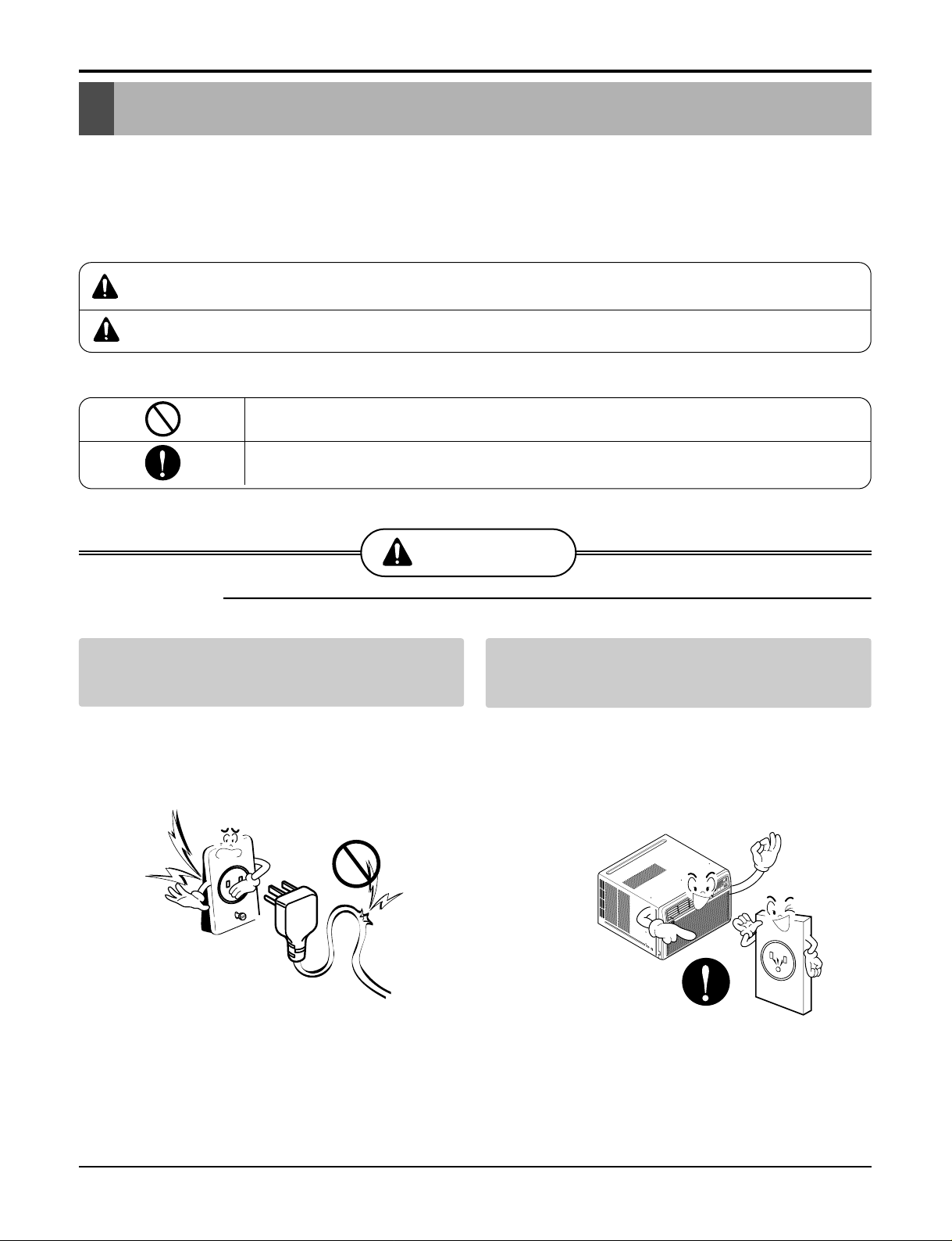
■ Installation
Do not use damaged power cord plugs, or a
loose socket.
• There is risk of fire or electric shock.
Always use the power plug and socket with
the ground terminal.
• There is risk of electric shock.
˚
C
TIMER
POW
ER
M
ODE
T
E
M
P
F
A
N
S
P
E
E
D
F
1
L
O
W
F
2
M
E
D
F
3
H
I
G
H
D
r
y
T
i
m
e
r
F
a
n
E
n
e
r
g
y
S
a
v
e
r
C
o
o
l
4 Room Air Conditioner
Safety Precautions
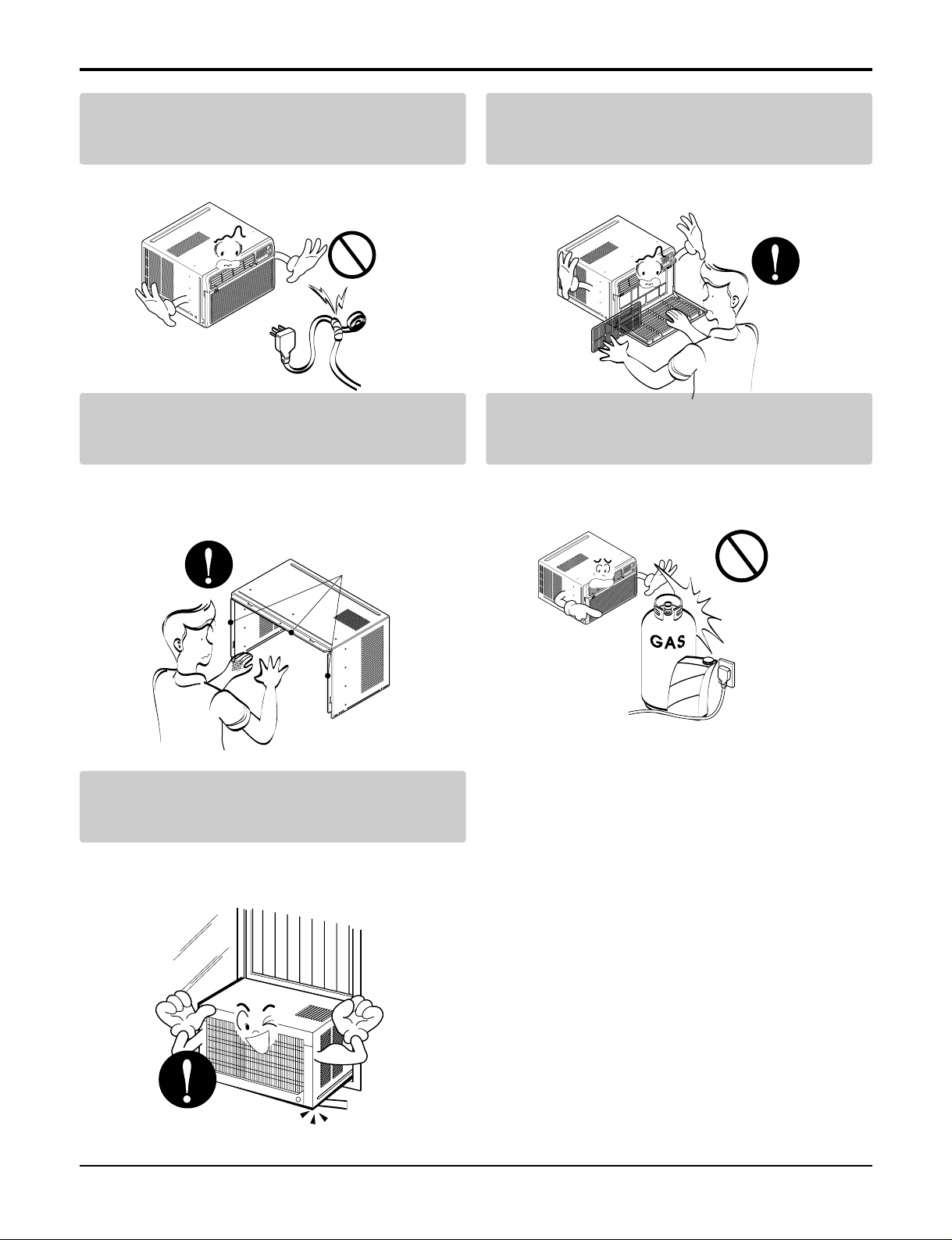
Do not modify or extend the power cord.
• There is risk or fire or electric shock.
Do not install, remove, or re-install the unit by
yourself(customer).
• There is risk of fire, electric shock, explosion, or injury.
Be cautious when unpacking and installing
the product.
• Sharp edges could cause injury. Be especially careful
of the case edges and the fins on the condenser and
evaporator.
Do not store or use flammable gas or combustibles near the air conditioner.
• There is risk of fire or failure of product.
Be sure the installation area does not deteriorate with age.
• If the base collapses, the air conditioner could fall with
it, causing property damage, product failure, and personal injury.
Sharp
edges
Gasolin
˚
C
T
I
M
E
R
P
O
W
E
R
M
O
D
E
T
E
M
P
F
A
N
S
P
E
E
D
F
1
L
O
W
F
2
M
E
D
F
3
H
I
G
H
D
r
y
T
i
m
e
r
F
a
n
E
n
e
r
g
y
S
a
v
e
r
C
o
o
l
˚
C
T
I
M
E
R
P
O
W
E
R
M
O
D
E
T
E
M
P
F
A
N
S
P
E
E
D
F
1
L
O
W
F
2
M
E
D
F
3
H
I
G
H
D
ry
T
im
e
r
Fan
E
ne
rg
y
S
av
er
Co
ol
˚
C
T
I
M
E
R
P
O
W
E
R
M
O
D
E
T
E
M
P
F
A
N
S
P
E
E
D
F
1
L
O
W
F
2
M
E
D
F
3
H
I
G
H
D
r
y
T
i
m
e
r
F
a
n
E
n
e
r
g
y
S
a
v
e
r
C
o
o
l
Service Manual 5
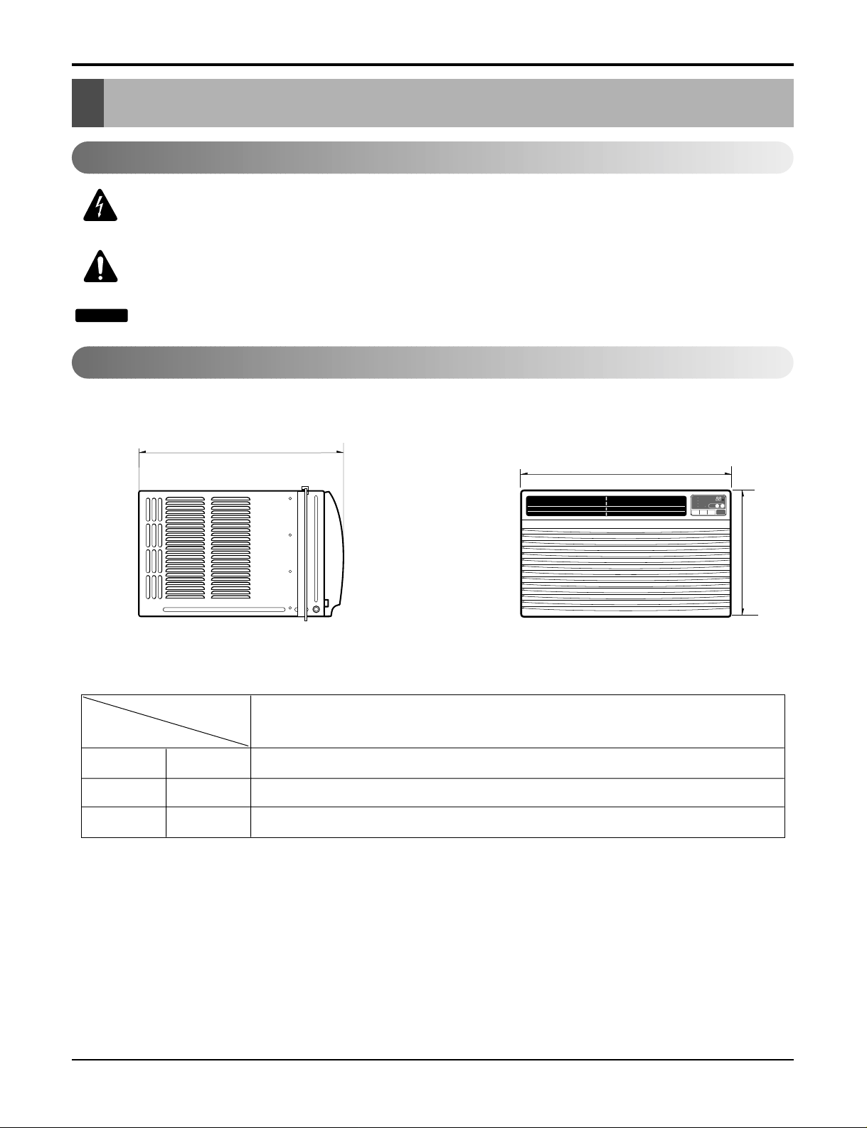
Dimensions
Dimensions
D
W
H
˚C
TIMER POWERMODE
TEMP
FAN
SPEED
F1 LOW
F2 MED
F3 HIGH
Dry Timer
Fan
Energy
Saver
Cool
W mm(inch) 600(23 5/8)
H mm(inch) 380(14 31/32)
D mm(inch) 567(22
5
/16)
Model
Dimension
All Models
Outside Dimensions
This symbol alerts you to the risk of electric shock.
This symbol alerts you to hazards that could cause harm to the
air conditioner.
This symbol indicates special notes.
NOTICE
Symbols Used in this Manual
6 Room Air Conditioner
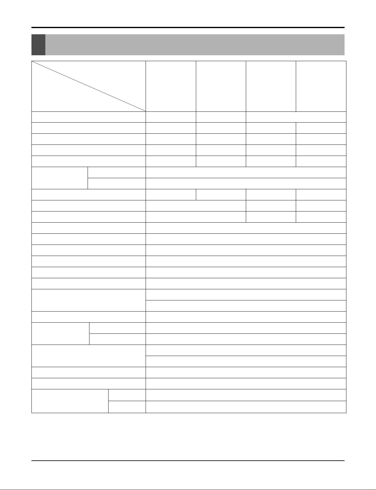
Specfications
Product Specifications
* DB : Dry Bulb
**
WB : Wet Bulb
NOTE: Please refer to Label Quality on the product since this specification may be changed for improving performance.
POWER SUPPLY
COOLING CAPACITY (Btu/h)
INPUT (W)
RUNNING CURRENT (A)
E.E.R (BTU/W.h)
INDOOR (°C)
OUTDOOR (°C)
REFRIGERANT (R-22) CHARGE
EVAPORATOR
CONDENSER
FAN, INDOOR
FAN, OUTDOOR
FAN SPEEDS, FAN/COOLING
FAN MOTOR
OPERATION CONTROL
ROOM TEMP. CONTROL
AIR DIRECTION CONTROL
CONSTRUCTION
PROTECTOR
COMPRESSOR
FAN MOTOR
POWER CORD
DRAIN SYSTEM
NET WEIGHT (lbs/kg)
OUTSIDE DIMENSION (inch)
(W x H x D) (mm)
1ø, 115, 60Hz 1ø, 208/230, 60Hz 1ø, 115, 60Hz
12,300 12,000 10,000 12,000
1,140 1,110 910 1,220
10.2 5.2 8.2 11.0
10.8 10.8 11.0 9.8
26.7(DB)* 19.4(WB)**
35(DB)* 23.9(WB)**
540g (19.0 oz) 550g (19.4 oz) 480(17.0 oz) 470(16.6 oz)
3 ROW 12 STACKS, SLIT-FIN TYPE
2 ROW 10 STACKS, LG-LOUVER TYPE
2 ROW 12 STACKS
2 ROW 17 STACKS, L-BENDED TYPE
2 ROW 17 STACKS, LG-LOUVER TYPE
2 ROW17 STACKS
TURBO FAN
PROPELLER TYPE FAN WITH SLINGER RING
3/3
6 POLES
REMOTE CONTROLLER
THERMISTOR
VERTICAL LOUVER (RIGHT & LEFT)
HORIZONTAL LOUVER (UP & DOWN)
SLIDE IN-OUT CHASSIS
OVERLOAD PROTECTOR
INTERNAL THERMAL PROTECTOR
(3 WIRE WITH GROUDING)
ATTACHMENT PLUG (CORD-CONNECTED TYPE)
DRAIN PIPE OR SPLASHED BY FAN SLINGER
79/36
235/8x 1431/32 x 225/16
600 x 380 x 560
MODELS
ITEMS
OPERATING
CONDITION
LW1200PR
LW1200ER
LWL1210WAL
LW1200ERY3
LW120CS
LB1200ER
LW1200PRY3
LWL1230WAL
LB1000ER
LW1004ER
LW1000PR
LW1000ER
LW1000ERY3
LW100CS
LW1000PRY3
WM-1231
Service Manual 7
Installation
Installation
Select the Best Location
Installation Check
How to Secure the Drain Pipe
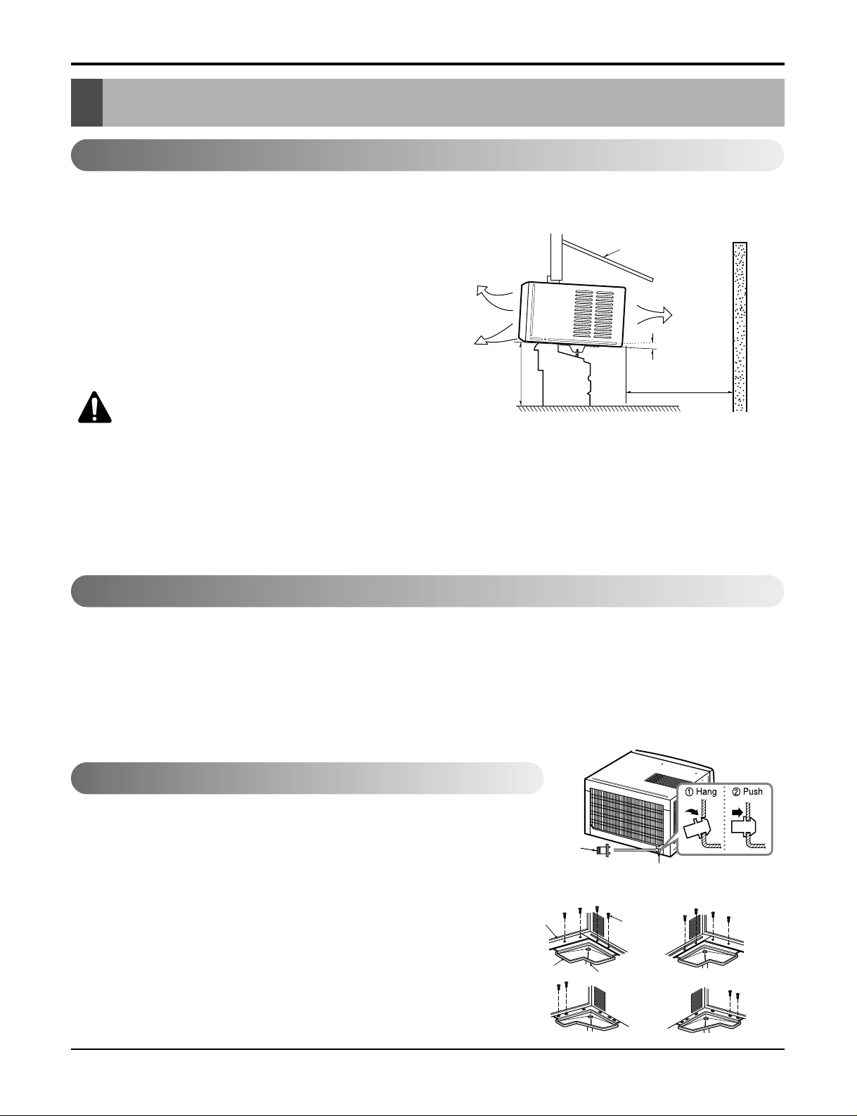
1.To prevent vibration and noise, make sure the unit is
installed securely and firmly.
2.Install the unit where the sunlight does not shine directly on the unit.
3.The outside of the cabinet must extend outward for at
least 12" and there should be no obstacles, such as a
fence or wall, within 20" from the back of the cabinet
because it will prevent heat radiation of the condenser.
Restriction of outside air will greatly reduce the cooling
efficiency of the air conditioner.
CAUTION: All side louvers of the cabinet
must remain exposed to the outside of
the structure.
4.Install the unit a little slanted so the back is slightly lower
than the front (about 1/
2"). This will help force con-densed
water to the outside.
5.Install the unit from the bottom about 30"~60" above the
floor level.
The setting conditions must be checked prior to initial starting.
The following items are especially important checking points when the installation is finished.
1. Grounding wire (Green or Green and Yellow) is provided in the power cord. The green wire must be grounded.
2. Connect to a single-outlet 15A circuit.
(or 20A circuit for Electric Heater Model)
3. To avoid vibration or noise, make sure the air conditioner is installed securely.
4 Avoid placing furniture or draperies in front of the air inlet and outlet.
In humid weather, excess water may cause the BASE PAN to overflow. To drain
the water, remove the DRAIN CAP and secure the DRAIN PIPE to the rear hole
of the BASE PAN. Press the drain pipe into the hole by pushing down and away
from the fins to avoid injury.
Optional
1. Install the drain pan over the corner of the cabinet where you removed
the plug with 4 (or 2) screws.
2. Connect the drain hose to the outlet located at the bottom of the drain
pan. You can purchase the drain hose or tubing locally to satisfy your
particular needs. (Drain hose is not supplied).
3. Select the most appropriate connection from among the following figures
(by considering the hole of the unit) to fit drain pan to your own unit.
AWNING
COOLED AIR
HEAT
RADIATION
30"~60"
ABOUT 1/2"
Over 20"
FENCE
Drain pipe
Drain cap
Fig. 4
Fig. 3
Fig. 2
DRAIN
PAN
DRAIN HOSE
Fig. 1
CABINET
SCREW
Figure 1
8 Room Air Conditioner
Installation
How to Install
When Using Gasket
When Using Installation Kits
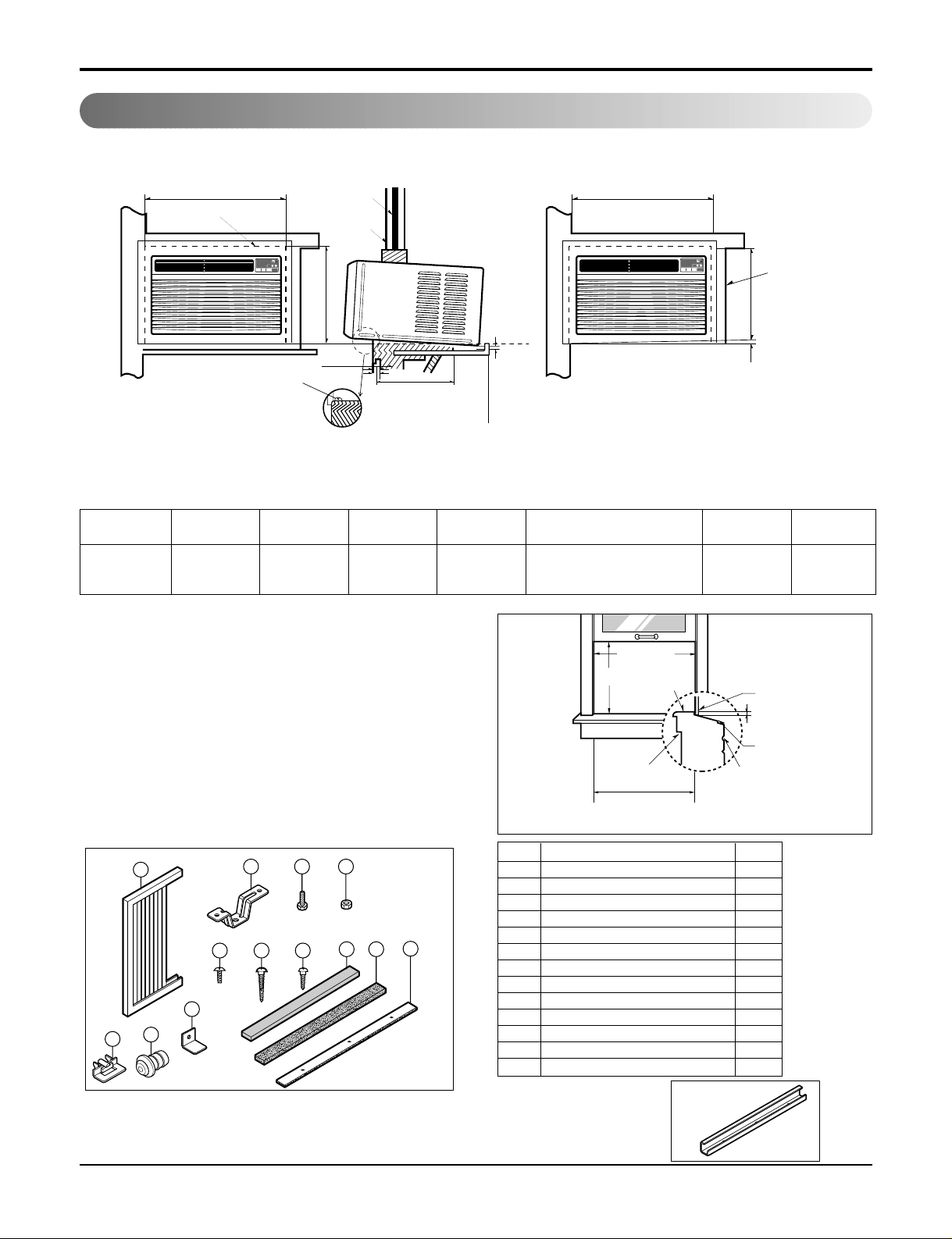
1. Window Requirements
This unit is designed for installation in
standard double hung windows with actual opening
widths from 27" to 39".
The top and bottom window sash must open sufficiently to allow a clear vertical opening of 16" from
the bottom of the upper sash to the window stool.
2. Installation Kits Contents
A
B
2
A
RIGHT SIDE
HORIZONTAL
LINE
B
DE
F
H
3
4
2
1
˚C
TIMER POWERMODE
TEMP
FAN
SPEED
F1 LOW
F2 MED
F3 HIGH
Dry Timer
Fan
Energy
Saver
Cool
˚C
TIMER POWERMODE
TEMP
FAN
SPEED
F1 LOW
F2 MED
F3 HIGH
Dry Timer
Fan
Energy
Saver
Cool
1. WINDOW (WIDTH-A, HEIGHT-B)
2. GASKET
3. WALL
4. DETAILS 5.1 x 30 ROUND HEAD WOOD
SCREWS
ABCDE F HI
625mm 392mm 280mm 30mm 0~25mm OVER 420mm 5~10mm -5~5mm
(245/8") (157/16") (111/32") (11/16") (0~1") (OVER 1617/32") (3/16"~3/8") (-3/16"~3/16")
27" to 39"
16" min
Stool
Interior wall
23
5
/8" min
(Without frame curtain)
Offset
1
/2" to 11/4"
Sill
Exterior
■ Top retainer bar is in
the product package.
NO. NAME OF PARTS Q'TY
1 FRAME CURTAIN 2
2 SILL SUPPORT 2
3 BOLT 2
4 NUT 2
5
SCREW(TYPE A) (10mm(2/5
"))
16
6
SCREW(TYPE B)
3
7
SCREW(TYPE C)
5
8 FOAM-STRIP 1
9
FOAM-PE (600mm x 25mm x 2mm)
1
10
WINDOW LOCKING BRACKET
1
11
FOAM-PE
(920mm x 30mm x 2mm)
1
12 DRAIN PIPE 1
13 FRAME GUIDE 2
D5.1mm(0.2")/16mm(0.63")
D4.1mm(0.17")/16mm(0.63")
2 3 4
13
1
10
12
8 11
765
9
Service Manual 9
Installation
Suggested Tool Requirements
SCREWDRIVER (+, -), RULER, KNIFE, HAMMER, PENCIL, LEVEL
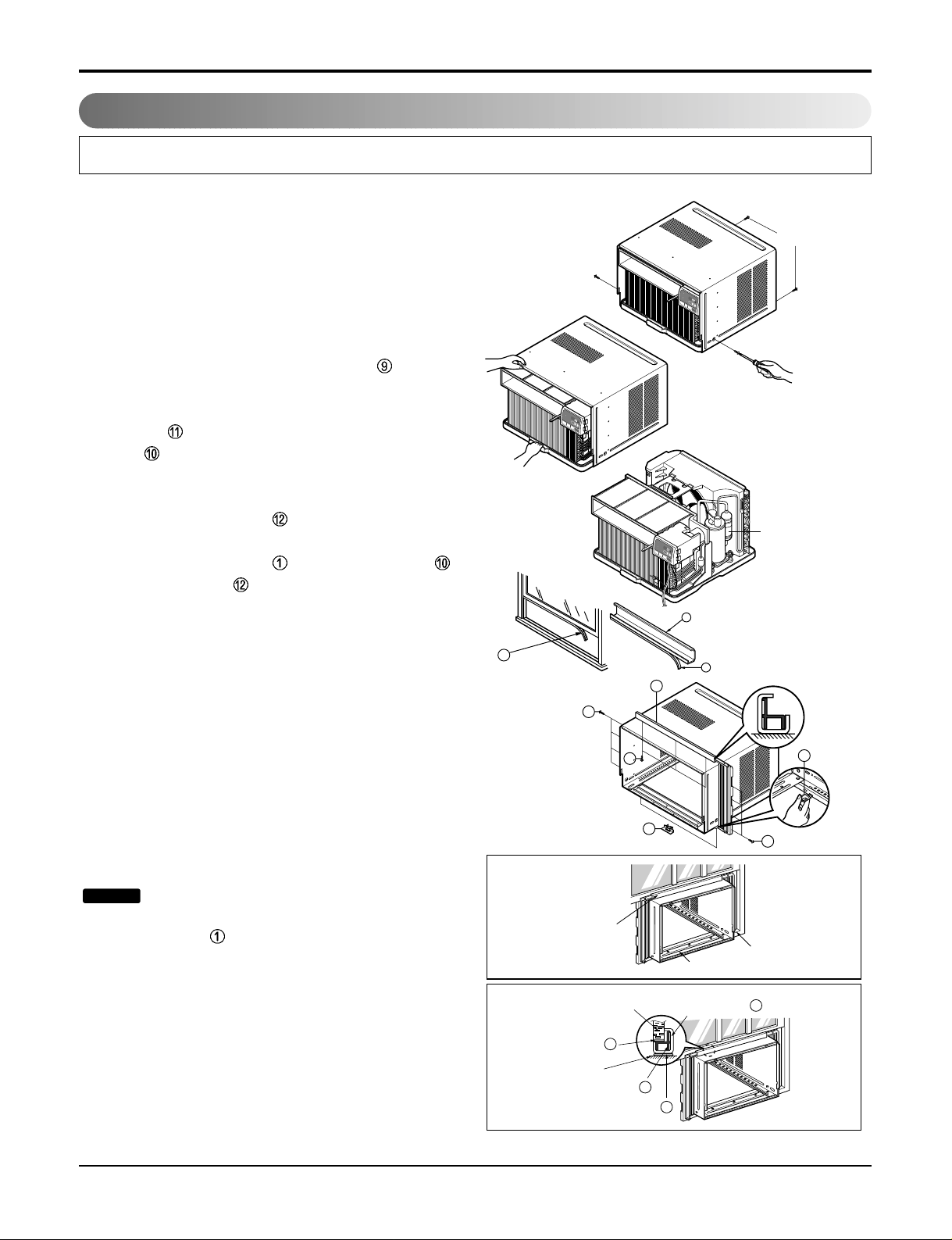
Preparation of Chassis
1. Remove the screws that fasten the cabinet at both
sides and at the back.
2. Slide the unit out from the cabinet by gripping the
base pan handle and pulling forward while
bracing the cabinet.
3. Cut the window sash seal to the proper length. Peel
off the backing and attach the Foam-Pe to the
underside of the window sash.
4. Remove the backing from the top upper guide
Foam PE and attach it to the bottom of the Upper
Guide .
5. Attach the upper guide onto the top of the cabinet
with 3 type A screws.
6. Insert the Frame Guides into the bottom of the
cabinet.
7. Insert the Frame Curtain into the upper guide
and Frame Guides .
8. Fasten the curtains to the unit with 4 Type A screws
at the both sides.
Cabinet Installation
1. Open the window. Mark a line on center of the window stool (or desired air conditioner location).
Carefully place the cabinet on the window stool and
align the center mark on the front angle with the
center line marked in the window stool.
2. Pull the bottom window sash down behind the
upper guide until it meets.
Do not pull the window sash down so
tightly that the movement of Frame
Curtain is restricted.
NOTICE
Shipping
Screws
9
10
13
(Type A)
(Type A)
5
5
11
11
9
5
EPS Material
Upper Guide
Window stool
Front Angle
Window Sash Upper guide
9
Frame Curtain
1
Foam-pe
10
Foam-pe
13
Cabinet
˚
C
T
E
M
P
F
1
LO
W
F
2 M
ED
F
3 H
IG
H
D
r
y
T
i
m
e
r
F
a
n
E
n
e
rg
y
S
av
e
r
C
o
o
l
T
I
M
E
R
P
O
W
E
RM
O
D
E
F
A
N
S
P
E
E
D
˚
C
T
E
M
P
F1
LO
W
F
2
M
ED
F
3
HI
GH
D
r
y
T
i
m
e
r
F
a
n
E
n
e
r
g
y
S
a
ve
r
C
o
o
l
T
I
M
E
R
P
O
W
E
RM
O
D
E
F
A
N
S
P
E
E
D
˚
C
T
E
M
P
F
1
L
OW
F2
M
E
D
F3
H
IG
H
D
r
y
T
i
m
e
r
F
a
n
E
n
e
r
g
y
S
a
v
e
r
C
o
o
l
T
I
M
E
R
P
O
W
E
R
M
O
D
E
F
A
N
S
P
E
E
D
Figure 2
Figure 3
10 Room Air Conditioner
Installation
INDOOR OUTDOOR
Sill Support
Nut
Bolt
2
4
3
INDOOR OUTDOOR
12
7
5
Frame Guide
About 1/2"
Screw(Type A)
Cabinet
6
2
About 1/2"
Screw(Type B)5Screw(Type A)
Sill support
Type C
Sash track
Front Angle
Screw(Type B)
6
Sill support
2
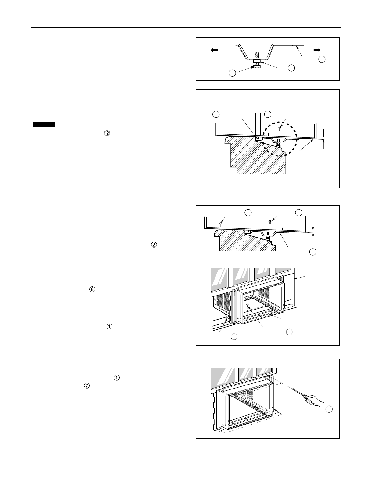
3. Loosely assemble the sill support using the parts
in
Figure 4.
4. Select the position that will place the sill
support near the outer most point on sill
(See
Figure
4)
Be careful when you install the cabinet
(Frame Guides
are broken easily).
5. Attach the sill support to the cabinet track hole in
relation to the selected position using
2 Type A screws in each support (See Figure 5).
6. The cabinet should be installed with a very slight
tilt (about 1/2") downward toward the outside
(See Figure 6).
Adjust the bolt and the nut of Sill Support for
balancing the cabinet.
7. Attach the cabinet to the window stool by
driving the screws (Type B) through the front
angle into window stool (5/8").
8. Pull each Frame Curtain properly to each window sash track, and repeat step 2.
9. Attach each Frame Curtain to the window sash
by using screws (Type C).
(See
Figure
7)
NOTICE
Figure 4
Figure 5
Figure 6
Figure 7
Service Manual 11
Installation
Screw(Type A)
Screw(Type A)
Power cord
13
8
Foam-Strip
˚C
T
E
M
P
F
1
L
O
W
F
2
M
E
D
F
3
H
IG
H
D
r
y
T
i
m
e
r
F
a
n
E
n
e
r
g
y
S
a
v
e
r
C
o
o
l
T
I
M
E
R
P
O
W
E
R
M
O
D
E
F
A
N
S
P
E
E
D
˚C
T
E
M
P
F
1
L
O
W
F
2
M
E
D
F
3
H
I
G
H
D
r
y
T
i
m
e
r
F
a
n
E
n
e
r
g
y
S
a
v
e
r
C
o
o
l
T
IM
E
R
P
O
W
E
R
M
O
D
E
F
A
N
S
P
E
E
D
˚C
TIMER POWERMODE
TEMP
FAN
SPEED
F1 LOW
F2 MED
F3 HIGH
Dry Timer
Fan
Energy
Saver
Cool
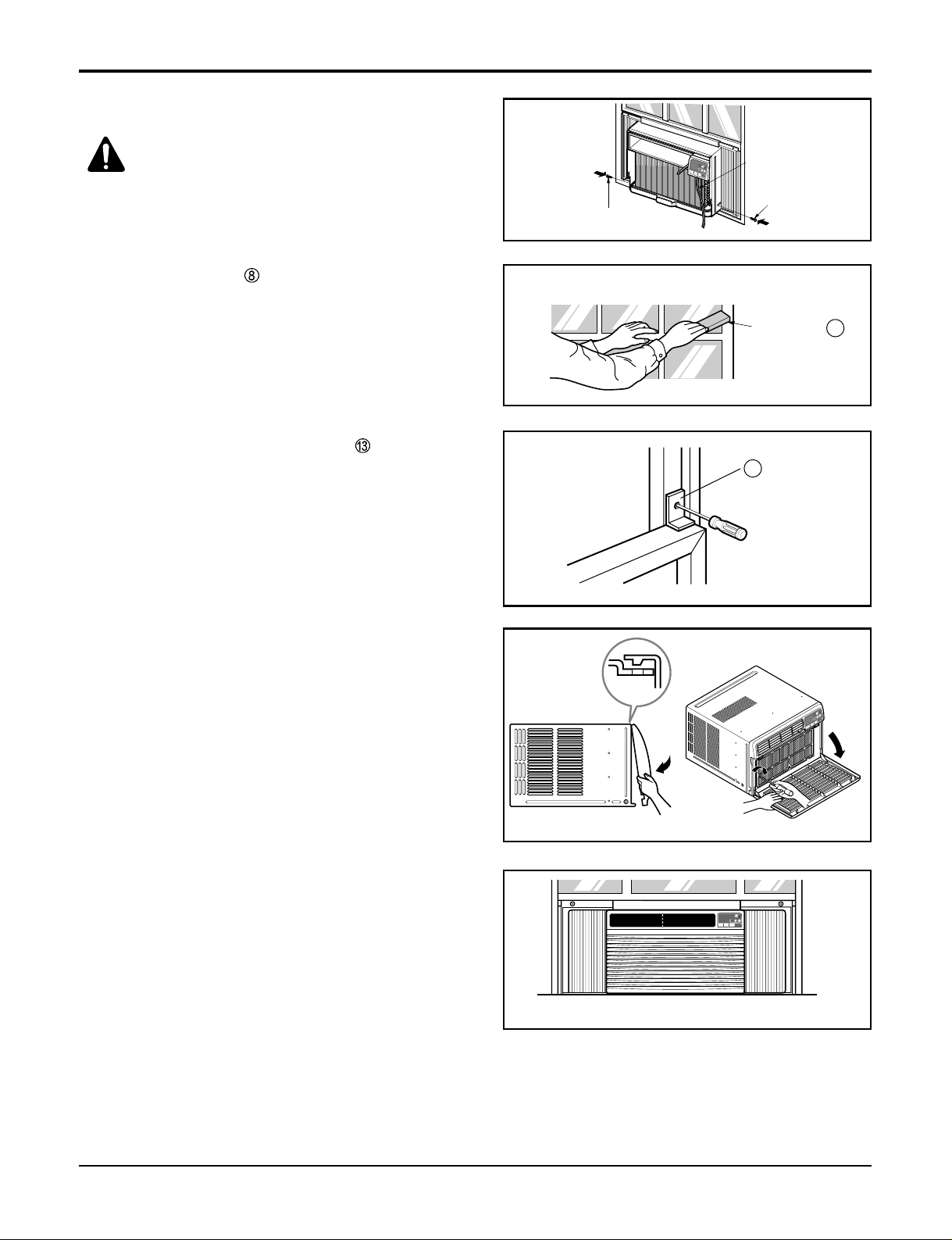
10. Slide the unit into the cabinet.(See Fig. 8)
CAUTION:
For security purpose, reinstall
screws (Type A) at the cabinet's sides.
11. Cut the Foam-Strip to the proper length and insert
between the upper and lower window sash.
(See Fig. 9)
12. Attach the window Locking Bracket with a type C
screw. (See Fig. 10)
13. Attach the front grille to the cabinet by inserting the
tabs on the grille into the tabs on the front of the cabinet. Push the grille in until it snaps into place.(See
Fig. 11)
14. Lift the inlet grille and secure it with a type A screw
through the front grille.(See Fig. 12)
Figure 11
Figure 8
Figure 9
Figure 10
Figure 13
Figure 12
12 Room Air Conditioner
Operation
• Designed for COOLING ONLY.
• Powerful and whispering cooling.
• Slide-in and slide-out chassis for the simple instal-
lation and service.
• Low air-intake, top cooled-air discharge.
• Built-in adjustable Thermistor
• Washable one-touch filter
• Compact size
• Reliable and efficient rotary compressor
Power
Temp
Fan Speed
Timer Mode
1
2
3
4
5
˚C
TIMER POWERMODE
TEMP
FAN
SPEED
F1 LOW
F2 MED
F3 HIGH
Dry Timer
Fan
Energy
Saver
Cool
1
2
6
3 45
TIMER MODE TEMP
POWER
FAN
SPEED
°F
12345
F1 LOW
F2 MED
F3 HIGH
COOLDRY
ENERGY
SAVER
FANTIMER
6
WM-1231, LW1000ERY3, LB1000ER
LB1200ER/LW1200ERY3
LW1004ER LW1200ER/LW1000ER
AIR
PURIFIER
CLEAN
FILTER
TIMER MODE
TEMP
POWER
FAN
SPEED
COOL
INDOOR DESIRED
ENERGY
SAVER
FAN
FAN
DRY
12345
6
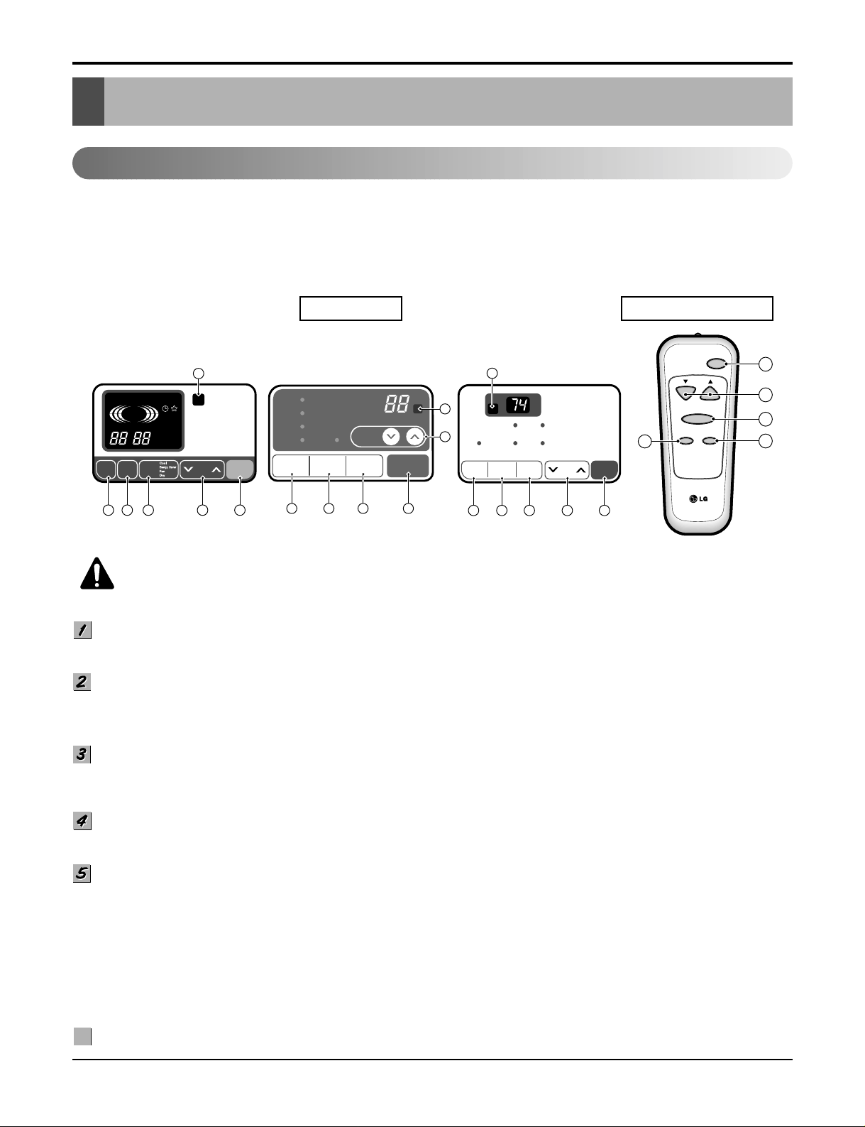
DISPLAY REMOTE CONTROL
PRECAUTION:
The Remote Control unit will not
function properly if bright light strikes the sensor window of the air conditioner or if
there are obstacles between the Remote Control unit and the air conditioner.
POWER BUTTON
To turn the air conditioner ON, push the button. To turn the air conditioner OFF, push the button again.
This button takes priority over any other buttons.
ROOM TEMPERATURE SETTING BUTTON
This button can automatically control the temperature of the room. The temperature can be set within a range of 60°F to
86°F by 1°F. (16°C to 30°C by 1°C)
Select the lower number for lower temperature of the room.
OPERATION MODE SELECTION BUTTON
Every time you push this button, it will shift among COOL, ENERGY SAVER, FAN and DRY.
-
Energy Saver: If Energy Save mode is selected, the fan stops when the compressor stops cooling.a
Approximately every 3 minutes the fan will turn on and check the room air to determine if cooling is needed.
FAN SPEED SELECTOR
Every time you push this button, it is set as follows.
(Hi [F3] ➔ Low [F1] ➔ Med [F2] ➔ Hi [F3] ➔ Low [F1] ➔...)
ON/OFF TIMER BUTTON
You can set the time when the unit will turn on or turn off automatically by pressing the timer button. If the unit is operating,
this button controls the time it will be turned off. If the unit is off state, this button controls the time it will start. Every time
you push this button, the remaining time will be set as follows.
- Stopping operation
(1Hour ➔ 2Hours ➔ 3Hours ➔ 4Hours ➔ 5Hours ➔ 6Hours ➔ 7Hours ➔ 8Hours ➔ 9Hours ➔ 10Hours ➔ 11Hours ➔
12Hours ➔ 0Hour ➔ 1Hour ➔ 2Hours ➔... )
- Starting operation
(1Hour ➔ 2Hours ➔ 3Hours ➔ 4Hours ➔ 5Hours ➔ 6Hours ➔ 7Hours ➔ 8Hours ➔ 9Hours ➔ 10Hours ➔ 11Hours ➔
12Hours ➔ off ➔ 1Hour ➔ 2Hours ➔ ... )
REMOCON SIGNAL RECEIVER
6
6
Operation
Function of Controls
POWER BUTTON
To turn the air conditioner ON, push the button. To turn the air conditioner OFF, push the button again.
This button takes priority over any other buttons.
ROOM TEMPERATURE SETTING BUTTON
This button can automatically control the temperature of the room. The temperature can be set within a range of 60°F to
86°F by 1°F. (16°C to 30°C by 1°C)
Select the lower number for lower temperature of the room.
OPERATION MODE SELECTION BUTTON
Every time you push this button, it will shift among COOL, ENERGY SAVER, FAN and DRY as follows.
-
Energy Saver: If Energy Save mode is selected, the fan stops when the compressor stops cooling.
Approximately every 3 minutes the fan will turn on and check the room air to determine if cooling is needed.
Service Manual 13
Operation
Precaution: The Remote Control unit will not function properly if strong light strikes the sensor window of the air
conditioner or if there are obstacles between the Remote Control unit and the air conditioner.
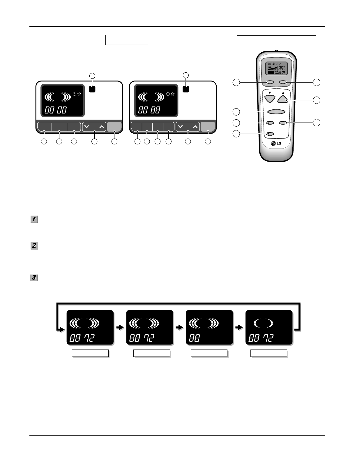
REMOTE CONTROL
DISPLAY
LW1200PR, LW1000PR, LWL1210WAL,
LWL1230WAL, LW100CS, LW120CS
6
DEFROST
HEATCOOL
FAN
DRY
FAN
ENERGY
SAVER
INDOOR DESIRED
FAN
TIMER MODE TEMP
SPEED
AIR
PURYFIER
AUTO
RESTART
POWER
LW1000PRY3, LW1200PRY3
COOL
INDOOR DESIRED
TIMER MODE
12345
FAN
FAN
FAN
SPEED
DRY
ENERGY
SAVER
AIR
PURIFIER
CLEAN
FILTER
AIR
PURIFIER
6
TEMP
POWER
127345
AIR
PURIFIER
Air
Power
7 1
4
8
5
Purifier
Temp
Fan Speed
Sleep Mode
Auto
Swing
Timer
2
3
FAN DRY HEAT
COOL
FAN
INDOOR DESIRED
COOL
DEFROST
ENERGY
SAVER
AIR
PURYFIER
AUTO
RESTART
COOL
FAN DRY HEAT
FAN
INDOOR DESIRED
ENERGY SAVER
DEFROST
ENERGY
SAVER
AIR
PURYFIER
AUTO
RESTART
COOL
DRY HEAT
FAN
FAN
INDOOR DESIRED
DEFROST
ENERGY
SAVER
AIR
PURYFIER
AUTO
RESTART
FAN DRY
FAN
COOL
DRY
FAN
INDOOR DESIRED
HEAT
DEFROST
ENERGY
SAVER
AIR
PURYFIER
AUTO
RESTART

14 Room Air Conditioner
Operation
FAN SPEED SELECTOR
Every time you push this button, it is set as follows.
(Hi ➔ Low ➔ Med ➔ Hi ➔ Low ➔...)
ON/OFF TIMER BUTTON
You can set the time when the unit will turn on or turn off automatically by pressing the timer button. If the unit is operating,
this button controls the time it will be turned off. If the unit is off state, this button controls the time it will start. Every time
you push this button, the remaining time will be set as follows.
- Stopping operation
(1Hour ➔ 2Hours ➔ 3Hours ➔ 4Hours ➔ 5Hours ➔ 6Hours ➔ 7Hours ➔ 8Hours ➔ 9Hours ➔ 10Hours ➔ 11Hours ➔
12Hours ➔ 0Hour ➔ 1Hour ➔ 2Hours ➔... )
- Starting operation
(1Hour ➔ 2Hours ➔ 3Hours ➔ 4Hours ➔ 5Hours ➔ 6Hours ➔ 7Hours ➔ 8Hours ➔ 9Hours ➔ 10Hours ➔ 11Hours ➔
12Hours ➔ off ➔ 1Hour ➔ 2Hours ➔ ... )
REMOCON SIGNAL RECEIVER
AIR PURIFIER
• Press the Air Purifier button.
Operation will start when the button is pressed and stop when the button is pressed again.
• Set the fan speed with the remote control. You can select the fan speed in three steps high, low or medium.
Each time the button is pressed, the fan speed mode is shifted.
• If you press the only Air Purifier button, only air purifying operates.
Then, fan speed is low. You can select the fan speed in three steps high, low or medium.
Each time the button is pressed, the fan speed mode is shifed.
SLEEP MODE
• Press the sleep mode button to set the time you want the unit to turn off automatically.
• Every time you push this button, the remaining time will be set as follows.
(1Hour ➔ 2Hours ➔ 3Hours ➔ 4Hours ➔ 5Hours ➔ 6Hours ➔ 7Hours ➔ 0Hour ➔ 1Hour ➔ 2Hours ➔
...
)
• The temperature setting will be raised by 2˚F in 30 minutes and by 4˚F in 1 hour to prevent overcooling during sleep.
6
6
7
7
8
8
HIGH LOW MID
COOL
AIR
PURYFIER
AUTO
RESTART
ENERGY
SAVER
DRY HEAT
DEFROST
INDOOR DESIRED
FAN
FAN COOL
AIR
PURYFIER
AUTO
RESTART
ENERGY
SAVER
DRY HEAT
DEFROST
INDOOR DESIRED
FAN
FANCOOL
AIR
PURYFIER
AUTO
RESTART
ENERGY
SAVER
DRY HEAT
DEFROST
INDOOR DESIRED
FAN
FAN
 Loading...