

LG LA240HSV3, LSU090HSV5, LA180HSV5, LA120HSV5, LAN120HSV5 Installation Manual
...
SINGLE-ZONE
ART COOLTM MIRROR WALL MOUNT
INSTALLATION MANUAL
Models:
LA090HSV5
LA120HSV5
LA180HSV5
LA240HSV3
PROPRIETARY DATA NOTICE
This document, as well as all reports, illustrations, data, information, and
other materials are the property of LG Electronics U.S.A., Inc., and are
disclosed by LG Electronics U.S.A., Inc., only in confidence.
This document is for design purposes only.
Do not throw away, destroy, or lose this manual.
Please read carefully and store in a safe place for future reference.
Content familiarity required for proper installation.
The instructions included in this manual must be followed to prevent product malfunction, property damage, injury, or death to the user or
other people. Incorrect operation due to ignoring any instructions will cause harm or damage. The level of seriousness is classified by the
symbols described below.
A summary list of safety precautions begins on page 3.
For more technical materials such as submittals, engineering
databooks, and catalogs, visit www.lghvac.com.
For continual product development, LG Electronics U.S.A., Inc., reserves the right to change specifications without notice.
This document, as well as all reports, illustrations, data, information, and other materials are the property of LG Electronics U.S.A., Inc.
IM_SZ_ArtCoolMirror_09_18
©LG Electronics U.S.A., Inc.
SAFETY INSTRUCTIONS
DANGER
The instructions below must be followed to prevent product malfunction, property damage, injury or death to the user or other people. Incorrect operation due to ignoring any instructions will cause harm or damage. The level of seriousness is classified by the symbols described
below.
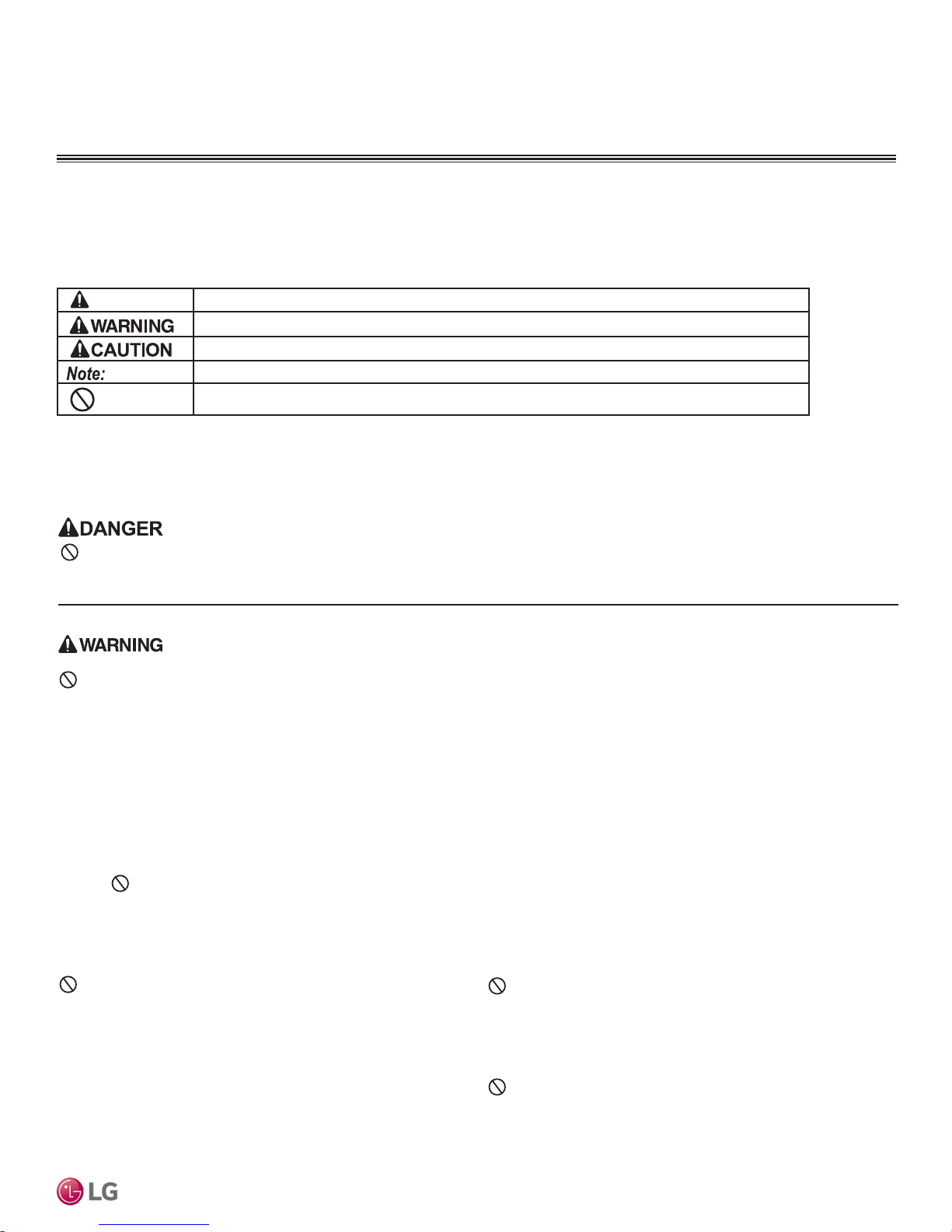
TABLE OF SYMBOLS
This symbol indicates an imminently hazardous situation which, if not avoided, will result in death or serious injury.
This symbol indicates a potentially hazardous situation which, if not avoided, could result in death or serious injury.
This symbol indicates a potentially hazardous situation which, if not avoided, may result in minor or moderate injury.
This symbol indicates situations that may result in equipment or property damage accidents only.
This symbol indicates an action must not be completed.
INSTALLATION
Don’t store or use ammable gas / combustibles near the unit.
There is risk of re, explosion, and physical injury or death.
Do not install or remove the unit by yourself (end user).
Ask the dealer or an LG trained service provider to install the
unit.
Improper installation by the user may result in water leakage, re,
explosion, electric shock, physical injury or death.
For replacement of an installed unit, always contact an LG
trained service provider.
There is risk of re, electric shock, explosion, and physical injury or
death.
The unit is shipped with refrigerant and the service valves
closed. Do not open service valves on the unit until all
non-condensibles have been removed from the piping system and authorization to do so has been obtained from the
commissioning agent.
There is a risk of physical injury or death.
Safety Instructions
Always check for system refrigerant leaks after the unit has
been installed or serviced.
Exposure to high concentration levels of refrigerant gas may lead to
illness or death.
Wear protective gloves when handling equipment. Sharp
edges may cause personal injury.
Dispose the packing materials safely.
• Packing materials, such as nails and other metal or wooden parts,
may cause puncture wounds or other injuries.
• Tear apart and throw away plastic packaging bags so that children
may not play with them and risk suffocation and death.
Install the unit considering the potential for strong winds or
earthquakes.
Improper installation may cause the unit to fall over, resulting in physical
injury or death.
Do not run the compressor with the service valves
closed.
There is a risk of explosion, physical injury, or death.
Periodically check that the outdoor frame is not damaged.
There is a risk of explosion, physical injury, or death.
Replace all control box and panel covers.
If cover panels are not installed securely, dust, water and animals may
enter the unit, causing re, electric shock, and physical injury or death.
Due to our policy of continuous product innovation, some specifications may change without notification.
©LG Electronics U.S.A., Inc., Englewood Cliffs, NJ. All rights reserved. “LG” is a registered trademark of LG Corp.
Do not change the settings of the protection devices.
If the pressure switch, thermal switch, or other protection device is
shorted and forced to operate improperly, or parts other than those
specied by LG are used, there is risk of re, electric shock, explosion,
and physical injury or death.
Do not install the unit on a defective stand.
There is a risk of physical injury.
3
SAFETY INSTRUCTIONS
INSTALLATION - CONTINUED
If the air conditioner is installed in a small space, take
measures to prevent the refrigerant concentration from
exceeding safety limits in the event of a refrigerant leak.
Install the unit in a safe location where nobody can step on or
fall onto it.
There is risk of physical injury or death.
Consult the latest edition of ASHRAE (American Society of Heating,
Refrigerating, and Air Conditioning Engineers) Standard 15. If the
refrigerant leaks and safety limits are exceeded, it could result in personal injuries or death from oxygen depletion.
Properly insulate all cold surfaces to prevent “sweating.”
Cold surfaces such as uninsulated piping can generate condensate
that could drip, causing a slippery surface that creates a risk of slipping,
falling, and personal injury.
Be very careful when transporting the product.
• Do not attempt to carry the product without assistance.
• Some products use polypropylene bands for packaging. Do not use polypropylene bands to lift the unit.
• Suspend the unit from the base at specified positions.
• Support the unit a minimum of four points to avoid slippage from rigging apparatus.
Do not install the unit in a noise sensitive area.
Don’t install the unit where it’s directly exposed to ocean
winds.
When connecting refrigerant tubing, remember to allow for
pipe expansion.
Improper piping may cause refrigerant leaks and system malfunction.
Ocean winds may cause corrosion, particularly on the condenser and
evaporator ns, which, in turn could cause product malfunction or inefcient performance.
When installing the unit in a low-lying area, or a location that
is not level, use a raised concrete pad or concrete blocks to
Mirror Wall Mount Installation Manual
provide a solid, level foundation.
TM
This may prevent water damage and reduce abnormal vibration.
Take appropriate actions at the end of HVAC equipment life
to recover, recycle, reclaim or destroy R410A refrigerant
according to applicable U.S. Environmental Protection
Agency (EPA) rules.
Periodically check that the outdoor frame is not damaged.
There is a risk of equipment damage.
Properly insulate all cold surfaces to prevent “sweating.”
Cold surfaces such as uninsulated piping can generate condensate that
may drip and cause a slippery surface condition and/or water damage to
walls.
When installing the unit in a hospital, mechanical room, or
similar electromagnetic eld (EMF) sensitive environment,
provide sufcient protection against electrical noise.
Inverter equipment, power generators, high-frequency medical equipment, or radio communication equipment may cause the air conditioner to
Single Zone Art Cool
operate improperly. The unit may also affect such equipment by creating
electrical noise that disturbs medical treatment or image broadcasting.
Do not use the product for special purposes such as
preserving foods, works of art, wine coolers, or other
precision air conditioning applications. The equipment is
designed to provide comfort cooling and heating.
There is risk of property damage.
Do not make refrigerant substitutions. Use R410A only.
If a different refrigerant is used, or air mixes with original refrigerant, the
unit will malfunction and be damaged.
Keep the unit upright during installation to avoid vibration or
water leakage.
Due to our policy of continuous product innovation, some specifications may change without notification.
4
©LG Electronics U.S.A., Inc., Englewood Cliffs, NJ. All rights reserved. “LG” is a registered trademark of LG Corp.
Install the unit in a safe location where nobody can step on or
fall onto it. Do not install the unit on a defective stand.
There is risk of unit and property damage.
Install the drain hose to ensure adequate drainage.
There is a risk of water leakage and property damage.
Don’t store or use ammable gas / combustibles near the
unit.
There is risk of product failure.
Always check for system refrigerant leaks after the unit has
been installed or serviced.
Low refrigerant levels may cause product failure
The unit is shipped with refrigerant and the service valves
closed. Do not open service valves on the unit until all
non-condensibles have been removed from the piping system
and authorization to do so has been obtained from the commissioning agent.
There is a risk of refrigerant contamination, refrigerant loss and equipment damage.
Do not run the compressor with the service valves closed.
There is a risk of equipment damage.
WIRING
High voltage electricity is required to operate this system.
Adhere to the National Electrical Codes and these
instructions when wiring.
Improper connections and inadequate grounding can cause accidental
injury or death.
Always ground the unit following local, state, and National
Electrical Codes.
The information contained in this manual is intended for use
by an industry-qualied, experienced, certied electrician
familiar with the U.S. National Electric Code (NEC) who is
equipped with the proper tools and test instruments.
Failure to carefully read and follow all instructions in this manual can
result in equipment malfunction, property damage, personal injury or
death.
SAFETY INSTRUCTIONS
Turn the power off at the nearest disconnect before servicing
the equipment.
Electrical shock can cause physical injury or death.
Properly size all circuit breakers or fuses.
There is risk of re, electric shock, explosion, physical injury or death.
Refer to local, state, and federal codes, and use power wires
of sufcient current capacity and rating.
Wires that are too small may generate heat and cause a re.
Secure all eld wiring connections with appropriate wire
strain relief.
Improperly securing wires will create undue stress on equipment power
lugs. Inadequate connections may generate heat, cause a re and
physical injury or death.
Safety Instructions
All electric work must be performed by a licensed electrician
and conform to local building codes or, in the absence of
local codes, with the National Electrical Code, and the
instructions given in this manual.
If the power source capacity is inadequate or the electric work is not
performed properly, it may result in re, electric shock, physical injury or
death.
Due to our policy of continuous product innovation, some specifications may change without notification.
©LG Electronics U.S.A., Inc., Englewood Cliffs, NJ. All rights reserved. “LG” is a registered trademark of LG Corp.
5
SAFETY INSTRUCTIONS
OPERATION
Do not provide power to or operate the unit if it is ood-
ed or submerged.
There is risk of re, electric shock, physical injury or death.
Use a dedicated power source for this product.
There is risk of re, electric shock, physical injury or death.
Do not allow water, dirt, or animals to enter the unit.
There is risk of re, electric shock, physical injury or death.
Avoid excessive cooling and periodically perform ventilation
to the unit.
Inadequate ventilation is a health hazard.
Do not touch the refrigerant piping during or after
operation.
It can cause burns or frostbite.
Do not operate the unit with the panel(s) or protective
cover(s) removed; keep ngers and clothing away from
moving parts.
The rotating, hot, cold, and high-voltage parts of the unit can cause
physical injury or death.
Mirror Wall Mount Installation Manual
TM
Periodically verify the equipment mounts have not
deteriorated.
If the base collapses, the unit could fall and cause physical injury or
death.
Do not operate the disconnect switch with wet hands.
There is risk of re, electric shock, physical injury or death.
If gas leaks out, ventilate the area before operating the unit.
If the unit is mounted in an enclosed, low-lying, or poorly ventilated area,
and the system develops a refrigerant leak, it may cause re electric
shock, explosion, physical injury or death.
Periodically check power cord and plug for damage.
Cord must be replaced by the manufacturer, its service agent, or similar
qualied persons in order to avoid physical injury and/or electric shock.
Do not open the inlet grille of the unit during operation.
Do not operate the unit with the panels or guards removed. Do not insert hands or other objects through the
inlet or outlet when the unit is plugged in. Do not touch
the electrostatic lter, if the unit includes one.
The unit contains sharp, rotating, hot, and high voltage parts that can
cause personal injury and/or electric shock.
Securely attach the electrical part cover to the indoor unit
and the service panel to the outdoor unit.
Non-secured covers can result in burns or electric shock due to dust or
water in the service panel.
To avoid physical injury, use caution when cleaning or servicing the air conditioner.
Clean up the site after installation is nished, and check
Single Zone Art Cool
that no metal scraps, screws, or bits of wiring have been left
inside or surrounding the unit.
Do not use this equipment in mission critical or specialpurpose applications such as preserving foods, works of art,
wine coolers or refrigeration. The equipment is designed to
provide comfort cooling and heating.
Oil, steam, sulfuric smoke, etc., can signicantly reduce the performance
of the unit, or damage its parts.
Provide power to the compressor crankcase heaters at least
six (6) hours before operation begins.
Starting operation with a cold compressor sump(s) may result in severe
bearing damage to the compressor(s). Keep the power switch on during
the operational season.
Due to our policy of continuous product innovation, some specifications may change without notification.
6
©LG Electronics U.S.A., Inc., Englewood Cliffs, NJ. All rights reserved. “LG” is a registered trademark of LG Corp.
Do not block the inlet or outlet.
Unit may malfunction.
Securely attach the electrical part cover to the indoor unit
and the service panel to the outdoor unit.
Non-secured covers can result in malfunction due to dust or water in the
service panel.
Periodically verify the equipment mounts have not
deteriorated.
If the base collapses, the unit could fall and cause property damage
or product failure.
Do not allow water, dirt, or animals to enter the unit.
There is risk of unit failure.
TABLE OF CONTENTS
Safety Instructions ............................................................................. 3-6
General Data ..................................................................................... 8-11
Unit Nomenclature ............................................................................... 8
Parts .................................................................................................... 9
Specications .................................................................................... 10
Electrical .............................................................................................11
General Installation Guidelines ..................................................... 12-22
Outdoor Unit Location Selection ................................................... 12-14
Required Outdoor Unit Clearances ................................................... 15
Rigging and Lifting ............................................................................. 16
Outdoor Unit Mounting ................................................................. 16-17
Required Indoor Unit Clearances ...................................................... 18
Indoor Unit Mounting .................................................................... 19-22
General Refrigerant Piping System Information ......................... 23-32
Refrigerant Safety Standards ............................................................23
Device Connection Limitations ..........................................................23
Selecting Copper Piping .................................................................... 24
Copper Expansion and Contraction .............................................. 25-26
Piping Materials and Handling ........................................................... 27
Refrigerant System Engineering ................................................... 28-30
Flaring and Brazing Procedures ................................................... 31-32
Refrigerant Piping Connections .................................................... 33-44
Installation Overview ......................................................................... 33
Special Applications .......................................................................... 34
Outdoor Unit Connections ................................................................. 35
Indoor Unit Connections ............................................................... 36-39
Outdoor Unit Drain Piping .................................................................. 40
Indoor Unit Drain Hose ................................................................. 40-42
Bundling ............................................................................................. 42
Insulation ...................................................................................... 43-44
Final Installation Procedures ........................................................ 58-67
Triple Leak / Pressure Test .......................................................... 58-59
Deep Evacuation Test .................................................................. 59-60
Triple Evacuation Test .................................................................. 60-61
Refrigerant Trim Charge ................................................................... 62
Finishing the Job .............................................................................. 62
Reattaching the Indoor Unit Bottom Cover ....................................... 63
Air Filter Disassembly and Assembly ............................................... 64
Installing Batteries, Test Run, Performance Evaluation ..................... 65
Installer Mode, Heating Only Mode ................................................... 66
Cooling Only Mode, Pump Down Procedure ..................................... 67
Troubleshooting .................................................................................. 68
LG SIMS - Self Diagnosis Functions ........................................... 68-69
Error Codes ................................................................................. 70-71
Refrigerant Leaks .............................................................................. 72
Installation Checklist ........................................................................... 73
Electrical System Installation ........................................................ 45-57
Safety Guidelines .............................................................................. 45
Connections and Specications ................................................... 45-50
Controller Options .............................................................................. 51
Indoor Unit Electrical Connections ............................................... 52-55
Outdoor Unit Electrical Connections ............................................. 56-57
Due to our policy of continuous product innovation, some specifications may change without notification.
©LG Electronics U.S.A., Inc., Englewood Cliffs, NJ. All rights reserved. “LG” is a registered trademark of LG Corp.
7
GENERAL DATA
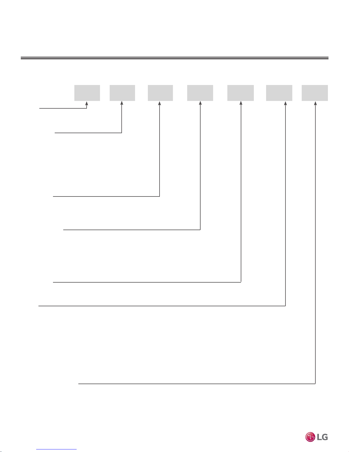
Unit Nomenclature
Indoor Units and Outdoor Units
L SV 5N
L = LG
Frame Type:
A: Art Cool™
S: Standard
C: Four-Way Ceiling-Cassette
D: Ceiling-Concealed Duct (Low Static)
H: Ceiling-Concealed Duct (High Static)
V: Vertical-Horizontal Air Handling
N: Indoor Unit
U: Outdoor Unit
No N or U: System
Capacity (Mbh)
9 = 9
12 = 12
Mirror Wall Mount Installation Manual
18 = 18
TM
24 = 24
36 = 36
42 = 42
48 = 48
A 180 H
System Type:
H = Heat Pump
Style:
SV = High Efficiency Inverter
VP = Gallery
YV = Premier
Single Zone Art Cool
EV = Mega
V = Standard Inverter
T = Thermostat Compatible
LV = Extended Piping
Generation or Revision
Due to our policy of continuous product innovation, some specifications may change without notification.
8
©LG Electronics U.S.A., Inc., Englewood Cliffs, NJ. All rights reserved. “LG” is a registered trademark of LG Corp.
Required Tools (field provided)
• Level
• Screwdriver
• Electrical lineman pliers
• Electric drill
• Hole saw
• Drill
• Flaring tool set
• Tubing cutter
• Tube/pipe reamer
• Torque wrenches
• Allen wrench
• Gas-leak detector
• Thermometer
• Measuring Tape
Required Parts (field provided)
• Connecting cable (power and control)
• Pipes - vapor line and liquid line, with insulation
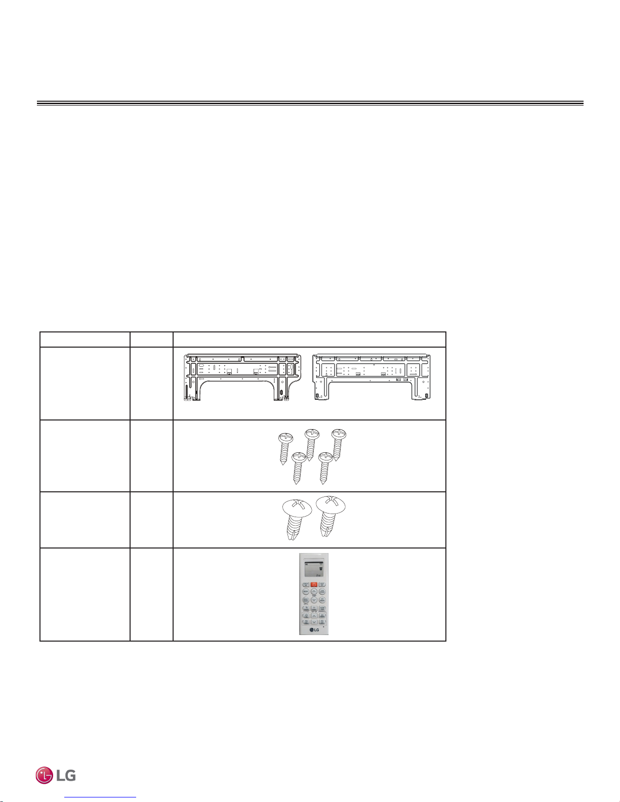
Included Parts
Part Quantity Image
GENERAL DATA
Parts
• Multimeter
• Ammeter
• Insulated drain hose
• Additional drain hose
Product Data
Installation Plate One (1)
Type “A” Screws Five (5)
Type “B” Screws
(M4 x 12L)
Wireless
Controller with Holder
AKB74955602
Two (2)
One (1)
7,000 ~ 15,000 Btu/h Indoor Units
18,000 and 24,000 Btu/h Indoor Units
Due to our policy of continuous product innovation, some specifications may change without notification.
©LG Electronics U.S.A., Inc., Englewood Cliffs, NJ. All rights reserved. “LG” is a registered trademark of LG Corp.
9
GENERAL DATA
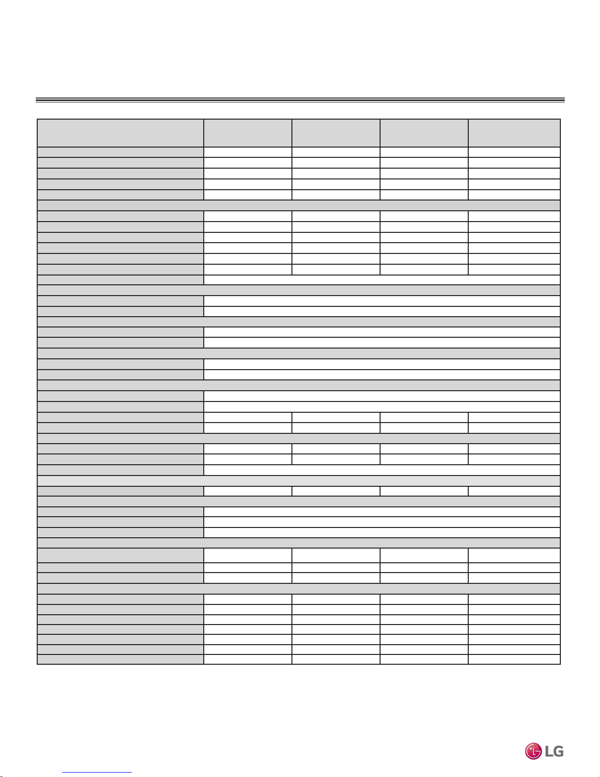
Specications
Table 1: Single Zone Art Cool Mirror Wall Mount System Specications.
System Model Number (IDU/ODU)
Cooling Capacity (Min/Rated/Max) (Btu/h) 1,023 ~ 9,000 ~ 12,625 1,023 ~ 12,000~ 13,785 3,070 ~ 18,000 ~ 29,515 3,070 ~ 22,000 ~ 30,030
Cooling Power Input1 (kW) 0.20 ~ 0.62 ~ 0.87 0.20 ~ 0.96 ~ 1.35 0.30 ~ 1.43 ~ 2.00 2.04
Heating Capacity (Min/Rated/Max) (Btu/h) 1,023 ~ 10,900 ~ 17,061 1,023 ~ 13,600 ~ 22,178 3,070 ~ 21,600 ~ 38,898 3,070 ~ 27,600 ~ 38,898
Heating Power Input1 (kW) 0.20 ~ 0.71 ~ 1.89 0.20 ~ 1.04 ~ 1.97 0.66 ~ 1.73 ~ 3.98 2.67
COP 4.50 3.83 3.66 3.03
Maximum Heating Capacity (Btu/h)
Outdoor 17°F (WB)/Indoor 70°F (DB) 11,080 (102%) 13,810 (102%) 22,340 (103%) 28,020 (102%)
Outdoor 5°F (WB)/Indoor 70°F (DB) 9,570 (88%) 11,930 (88%) 19,300 (89%) 24,220 (88%)
Outdoor -4 °F (WB)/Indoor 70°F (DB)
EER 14.52 12.50 12.58 10.78
SEER 23.50 22.70 21.50 20.0
HSPF 11.3 11.4 10.2 10.0
Power Supply (V/Hz/Ø) 208-230 / 60 / 1
Outdoor Unit Operating Range
Cooling (°F DB) 14 to 118
Heating (°F WB) -4 to 65
Indoor Unit Operating Range
Cooling (°F WB) 53 to 75
Heating (°F DB) 60 to 86
Indoor Temperature Setting Range
Cooling (°F) 64 to 86
Heating (°F) 60 to 86
Unit Data
Refrigerant Type
3
Refrigerant Control EEV
IDU Sound Pressure4 dB(A) (H/M/L/Sleep) 39 / 33 / 23 / 19 39 / 33 / 23 / 19 45 / 40 / 35 / 29 45/40/35/29
ODU Sound Pressure4 dB(A) (Cool/Heat)
Mirror Wall Mount Installation Manual
Unit Weight (lbs)
TM
IDU (Net/Shipping) 20.5/ 25.6 20.5/ 25.6 29.8/36.4 32/39
ODU (Net/Shipping) 74.1 / 78.9 74.1 / 78.9 116.8 / 126.5 121/131
Power/Communication Cable
Compressor
Compressor Type (Qty) Twin Rotary (1) Twin Rotary (1) Twin Rotary (1) Twin Rotary (1)
Fan
IDU Type (Qty) Cross Flow (1)
ODU Type (Qty) Propeller (1)
Motor/Drive Brushless Digitally Controlled/Direct
Airflow Rate
IDU Cooling (Max /H /M /L [CFM]) 459 / 338 / 317 / 194 459 / 338 / 317 / 194 706 / 530 / 477 / 371 735 / 622 / 509 / 339
IDU Heating (Max /H /M /L [CFM]) 459 / 338 / 317 / 229 459 / 338 / 317 / 229 706 / 547 / 494 / 371 735 / 622 / 509 / 339
Single Zone Art Cool
ODU Max (CFM) 1,165 1,165 2,119 2,119
Piping
Liquid Line (in, OD) ø1/4 ø1/4 ø3/8 3/8
Vapor Line (in, OD) ø3/8 ø3/8 ø5/8 5/8
Condensation Line (OD, ID) 27/32, 5/8 27/32, 5/8 27/32, 5/8 27/32, 5/8
Additional Refrigerant Charge (oz/ft) 0.22 0.22 0.38 0.38
Pipe Length6 (Min./Std./Max.) (ft.) 9.8 / 24.6 / 82 9.8 / 24.6 / 82 9.8 / 24.6 / 114.8 9.8 / 24.6 / 98.4
Piping Length6 (no add’l refrigerant, ft) 41.0 41.0 24.6 24.6
Max Elevation Difference (ft) 49.2 49.2 49.2 49.2
EEV: Electronic Expansion Valve IDU: Indoor Unit ODU: Outdoor Unit
This unit comes with a dry helium charge.
This data is rated 0 ft above sea level, with 24.6 ft of refrigerant line per indoor unit and a 0 ft level difference between
outdoor and indoor units.
Cooling capacity rating obtained with air entering the indoor coil at 80ºF dry bulb (DB) and 67ºF wet bulb (WB); and
outdoor ambient conditions of 95ºF dry bulb (DB) and 75ºF wet bulb (WB). Heating capacity rating obtained with air
entering the indoor unit at 70ºF dry bulb (DB) and 60ºF wet bulb (WB); and outdoor ambient conditions of 47ºF dry bulb
(DB) and 43ºF wet bulb (WB).
1 Power Input is rated at high speed.
10
2
5
(No. x AWG) 4 x 18
Due to our policy of continuous product innovation, some specifications may change without notification.
©LG Electronics U.S.A., Inc., Englewood Cliffs, NJ. All rights reserved. “LG” is a registered trademark of LG Corp.
LA090HSV5
(LAN090HSV5/
LSU090HSV5
LA120HSV5
(LAN120HSV5/
LSU120HSV5)
LA180HSV5
(LAN180HSV5/
LSU180HSV5)
8,310 (76%) 10,360 (76%) 16,760 (77%)
R410A
45 / 48 45 / 48
2 Optional low Ambient Wind Baffle Kit allows operation down to 0°F in cooling mode.
3 Take appropriate actions at the end of HVAC equipment life to recover, recycle, reclaim or destroy R410A refrigerant
according to applicable regulations (40 CFR Part 82, Subpart F) under section 608 of CAA.
4 Sound pressure levels are tested in an anechoic chamber under ISO Standard 1996.
5 All communication / connection (power) cable from the outdoor unit to the indoor unit are field supplied and is to be
minimum four-conductor, 18 AWG, stranded, shielded or unshielded (if shielded, it must be grounded to the chassis of the
outdoor unit only), and must comply with applicable local and national codes.
6. Piping lengths are equivalent.
53 / 53 53 / 53
LA240HSV3
(LAN240HSV3/
LAU240HSV3)
21,030 (76%)
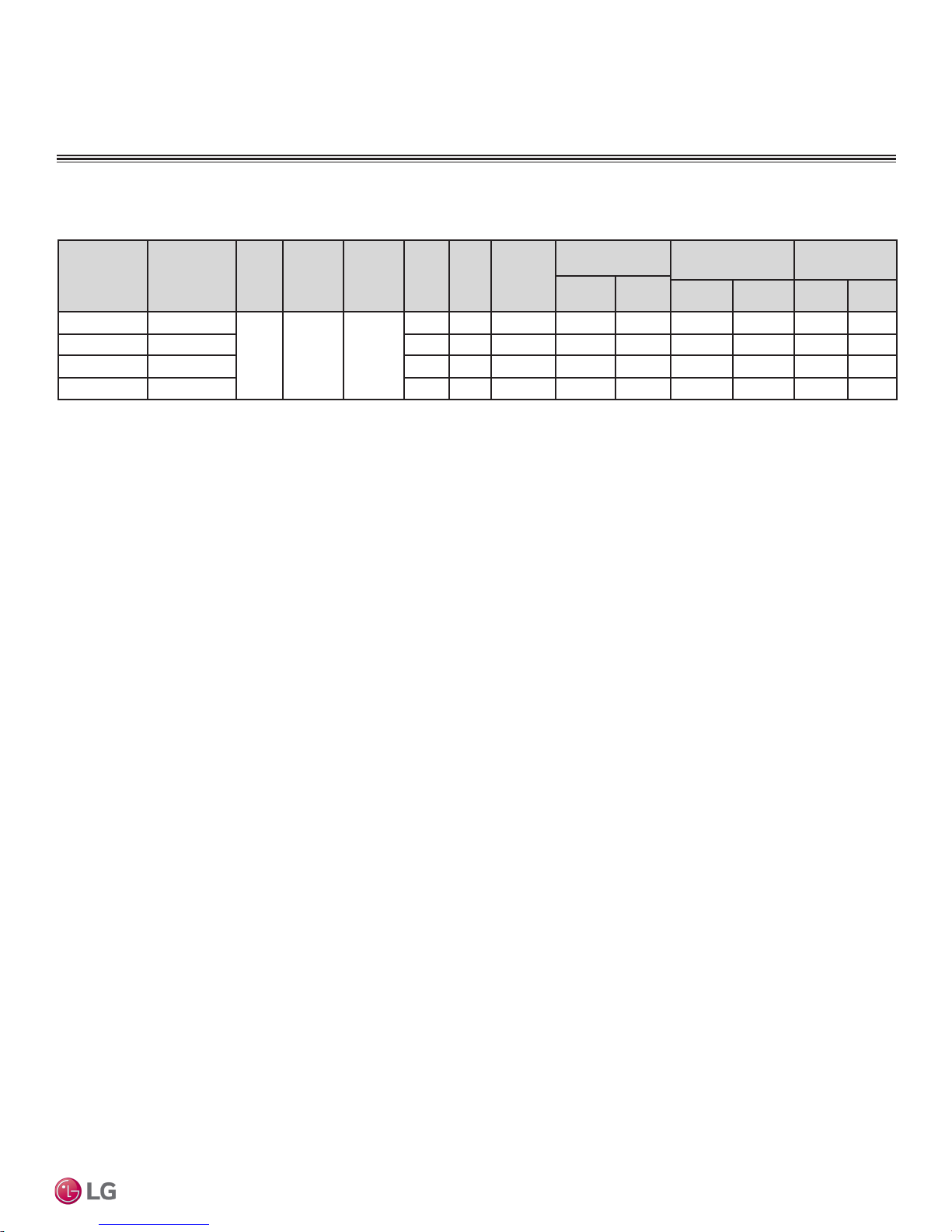
Electrical Data
Table 2: Single Zone Art Cool Mirror Wall Mount Electrical Data.
GENERAL DATA
Electrical Data
Voltage
Indoor Unit Outdoor Unit Hertz Voltage
Range
(Min. to
MCA MOP
Max.)
LAN090HSV5 LSU090HSV5
LAN120HSV5 LSU120HSV5
LAN180HSV5 LSU180HSV5
LAN240HSV3 LAU240HSV3 19.0 25.0 1 14.6 14.6 124 0.25 30 0.4
Voltage tolerance is ±10%.
Maximum allowable voltage unbalance is 2%.
MCA = Minimum Circuit Ampacity.
Maximum Overcurrent Protection (MOP) is calculated as
follows: (Largest motor FLA x 2.25) + (Sum of other motor
60 208 - 230 187 - 253
FLA) rounded down to the nearest standard fuse size.
RLA = Rated Load Amps.
FLA = Full Load Amps.
W: Fan Motor Rated Output (W).
10.0 15.0 1 7.0 7.0 43 0.4 30 0.4
10.0 15.0 1 7.0 7.0 43 0.4 30 0.4
13.0 20.0 1 9.6 9.6 124 0.25 70 0.4
Com-
pressor
Quantity
Compressor
Motor RLA
Cooling
Heat-
ing
Outdoor Fan
Motor
Indoor Fan
Motor
W FLA W FLA
Product Data
Due to our policy of continuous product innovation, some specifications may change without notification.
©LG Electronics U.S.A., Inc., Englewood Cliffs, NJ. All rights reserved. “LG” is a registered trademark of LG Corp.
11

GENERAL INSTALLATION GUIDELINES
DANGER
WARNING
Outdoor Unit Location Selection
Selecting the Best Location for the Outdoor Unit
• Do not install the unit in an area where combustible gas may generate, flow, stagnate, or leak. These conditions can cause a fire, resulting
in bodily injury or death.
• Do not install the unit in a location where acidic solution and spray (sulfur) are often used as it can cause bodily injury or death.
• Do not use the unit in environments where oil, steam, or sulfuric gas are present as it can cause bodily injury or death.
When deciding on a location to place the outdoor unit, be sure to choose an area where run-off water from defrost cycle will not accumulate and
freeze on sidewalks or driveways, which may create unsafe conditions. Properly install and insulate any drain hoses to prevent the hose from freezing, cracking, leaking, and causing unsafe conditions from frozen condensate.
Install a fence to prevent vermin from crawling into the unit or unauthorized individuals from accessing it. Vermin and unauthorized individuals may
cause a re, electric shock, physical injury or death. Follow the placement guidelines set forth in “Clearance Requirements”.
Install a fence to prevent vermin from crawling into the unit or unauthorized individuals from accessing it. Vermin and unauthorized individuals may
damage the unit. Follow the placement guidelines set forth in “Clearance Requirements”.
Select a location for installing the outdoor unit that will meet the following conditions:
• Where there is enough structural strength to bear the weight of the unit.
• A location that allows for optimum air flow and is easily accessible for inspection, maintenance, and service.
• Where piping between the outdoor unit and indoor unit is within allowable limits.
• Include space for drainage to ensure condensate flows properly out of the unit when it is in heating mode. Avoid placing the outdoor unit in
a low-lying area where water could accumulate.
• If the outdoor unit is installed in a highly humid environment (near an ocean, lake, etc.), ensure that the site is well-ventilated and has a lot
of natural light (Example: Install on a rooftop).
Mirror Wall Mount Installation Manual
TM
Single Zone Art Cool
Dont’s
• Where it will be subjected to direct thermal radiation from other heat sources, or an area that would expose the outdoor unit to heat or steam
like discharge from boiler stacks, chimneys, steam relief ports, other air conditioning units, kitchen vents, plumbing vents, and other sources
of extreme temperatures.
• Where high-frequency electrical noise / electromagnetic waves will affect operation.
• Where operating sound from the unit will disturb inhabitants of surrounding buildings.
• Where the unit will be exposed to direct, strong winds.
• Where the discharge of one outdoor unit will blow into the inlet side of an adjacent unit (when installing multiple outdoor units).
Planning for Snow and Ice
To ensure the outdoor unit operates properly, certain measures are required in locations where there is a possibility of heavy snowfall or
severe windchill or cold:
1. Prepare for severe winter wind chills and heavy snowfall, even in areas of the country where these are unusual phenomena.
2. Position the outdoor unit so that its airflow fans are not buried by direct, heavy snowfall. If snow piles up and blocks the airflow, the sys-
tem may malfunction.
3. Remove any snow that has accumulated four (4) inches or more on the top of the outdoor unit.
4. In climates that may experience significant snow buildup, mount the outdoor unit on a raised, field-provided platform or stand. The raised
support platform must be high enough to allow the unit to remain above possible snow drifts, and must be higher than the maximum anticipated snowfall for the location.
5. Design the mounting base to prevent snow accumulation on the platform in front or back of the unit frame.
6. Provide a field fabricated snow protection hood to keep snow and ice and/or drifting snow from accumulating on the coil surfaces.
7. To prevent snow and heavy rain from entering the outdoor unit, install the condenser air inlets and outlets facing away from direct
winds.
8. Consider tie-down requirements in case of high winds or where required by local codes.
Due to our policy of continuous product innovation, some specifications may change without notification.
12
©LG Electronics U.S.A., Inc., Englewood Cliffs, NJ. All rights reserved. “LG” is a registered trademark of LG Corp.
GENERAL INSTALLATION GUIDELINES
Outdoor Unit Location Selection
Planning for Snow and Ice, continued.
When deciding on a location to place the outdoor unit, be sure to choose an area where run-off water from defrost cycle will not accumulate and
freeze on sidewalks or driveways, which may create unsafe conditions. Properly install and insulate any drain hoses to prevent the hose from freezing, cracking, leaking, and causing unsafe conditions from frozen condensate.
Choose an area where run-off water from defrost cycle will not accumulate and freeze on sidewalks or driveways. Properly install and insulate any
drain hoses to prevent the hose from freezing, cracking, leaking, and damaging the outdoor unit.
The indoor unit may take longer to provide heat, or heating performance will be reduced in winter if the unit is installed in the following locations:
• In a narrow, shady location.
• Near a location that has a lot of ground moisture.
• In a highly humid environment.
• In an area in which condensate does not drain properly.
General Installation Guidelines
Tie-Downs and Lightning Protection
Tie-Downs
• The strength of the roof must be checked before installing the
outdoor units.
• If the installation site is prone to high winds or earthquakes, when
installing on the wall or roof, securely anchor the mounting base
using a field-provided tie-down configuration approved by a local
professional engineer.
• The overall tie-down configuration must be approved by a local
professional engineer.
Always refer to local code when using a wind restraint system.
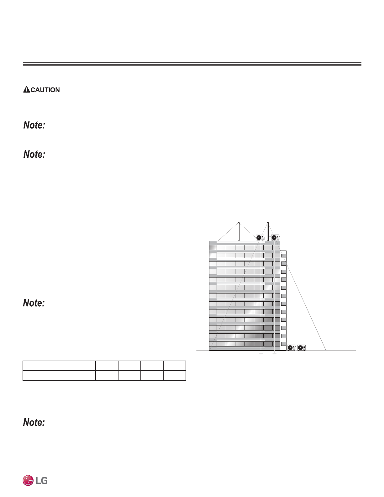
Lightning Protection
• To protect the outdoor unit from lightning, it must be placed within
the specified lightning safety zone.
Table 3: Safety Zone Specifications.
Building Height (feet) 66 98 148 197
Protection Angle (˚) 55 45 35 25
Figure 1: Lightning Protection Diagram.
Lightning rod
Lightning rod
Protection Angle (25˚~55˚)
5 feet
Ground
Safe zone
• Power cable and communication cable must be installed five (5) feet away from lightning rod.
• A high-resistance ground system must be included to protect against induced lightning or indirect strike.
If the building does not include lightning protection, the outdoor unit may be damaged from a lightening strike. Inform the customer of this possibility
in advance.
Due to our policy of continuous product innovation, some specifications may change without notification.
©LG Electronics U.S.A., Inc., Englewood Cliffs, NJ. All rights reserved. “LG” is a registered trademark of LG Corp.
13
GENERAL INSTALLATION GUIDELINES
Sea wind
Windbreak
Sea wind
Sea wind
Building
Building
Outdoor Unit Location Selection
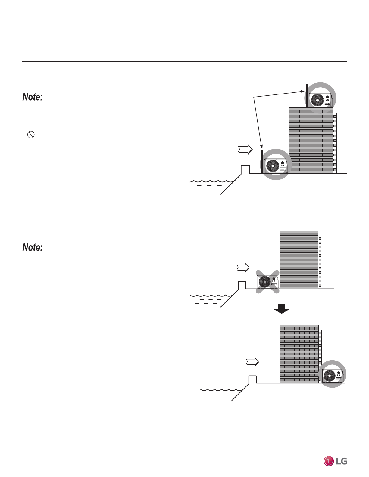
Oceanside Applications
Use of a Windbreak to Shield from Sea Wind
Ocean winds may cause corrosion, particularly on the condenser and
evaporator ns, which, in turn could cause product malfunction or inefcient performance.
• Avoid installing the outdoor unit where it would be directly
exposed to ocean winds.
• Install the outdoor unit on the side of the building opposite from
direct ocean winds.
• Select a location with good drainage.
• Periodically clean dust or salt particles off of the heat exchanger
with water.
• If the outdoor unit must be placed in a location where it would
be subjected to direct ocean winds, install a concrete windbreak
strong enough to block any winds.
• Windbreak must be more than 150% of the outdoor unit’s height.
There must be 2 to 3-1/2 inches of clearance between the outdoor
unit and the windbreaker for purposes of air flow.
Figure 2: Oceanside Placement Using Windbreak.
Figure 3: Placement Using Building as Shield.
Additional anti-corrosion treatment may need to be applied to the outdoor unit at oceanside locations.
Mirror Wall Mount Installation Manual
TM
Use of a Building to Shield from Sea Wind
If a windbreak is not possible, a building or larger structure must be
used to shield the outdoor unit from direct exposure to the sea wind.
The unit must be placed on the side of the building directly opposite
to the direction of the wind as shown at right.
Single Zone Art Cool
Due to our policy of continuous product innovation, some specifications may change without notification.
14
©LG Electronics U.S.A., Inc., Englewood Cliffs, NJ. All rights reserved. “LG” is a registered trademark of LG Corp.
GENERAL INSTALLATION GUIDELINES
Case 1
Case 2 Case 3
Required Outdoor Unit Clearances
Minimum Clearance Requirements for Single Fan Outdoor Units
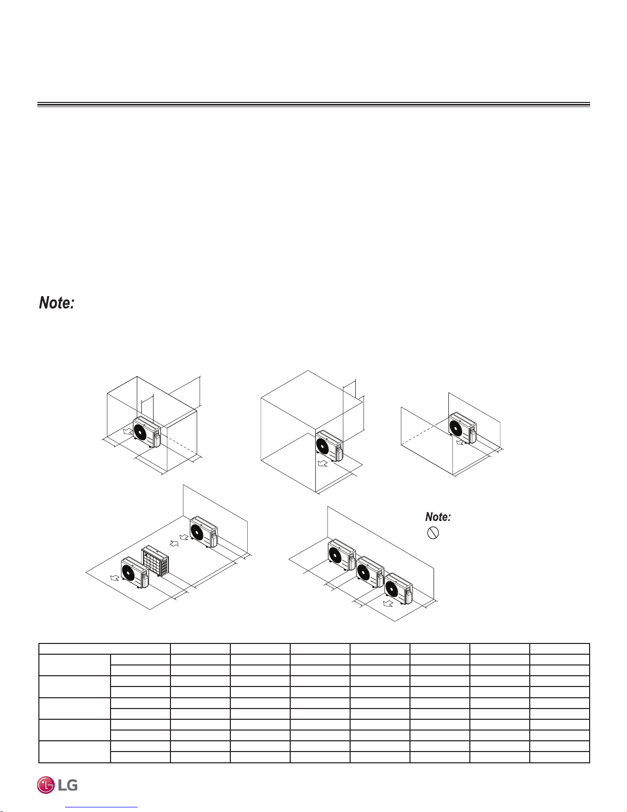
Proper clearance for the outdoor unit coil is critical for proper operation. When installing the outdoor unit, consider service, inlet and outlet,
and minimum allowable space requirements as illustrated in the diagrams below.
Specific clearance requirements in the diagram below are for single fan outdoor units. Figure below shows the overall minimum clearances
that must be observed for safe operation and adequate airflow around the outdoor unit.
When placing the outdoor unit under an overhang, awning, sunroof or other “roof-like structure”, observe the clearance requirements (as
shown in Cases 1 and 2) for height in relation to the unit. This clearance ensures that heat radiation from the condenser is not restricted
around the unit.
Adhere to all clearance requirements if installing the unit on a roof. Be sure to level the unit and ensure that the unit is adequately anchored.
Consult local codes for rooftop mounting requirements. To have successful service access to the outdoor unit, see figure below for minimum
spacing. When installing multiple outdoor units, see Cases 4 and 5 in the figure below for correct spacing requirements. Outdoor unit fans
draw air from the back of the unit and discharge out the front. Place units back to back and front to front.
If the outdoor unit is installed between standard and minimum clearances, capacity decreases approximately 10%.
Figure 4: Single Fan Outdoor Unit Service Access and Allowable Clearances Diagram.
General Installation Guidelines
1/16 inch
20 inches or less
B
A
Case 4
20 inches or less
B
G
D
Case 5
D
F
E
Table 4: Single Fan Outdoor Unit Service Access and Allowable Clearances Diagram Legend.
Unit: Inch A B C D E F G
Case 1
Case 2
Case 3
Case 4
Case 5
Standard 12 24 - 12 - - Minimum 4 10 - 4 - - 40
Standard - - 20 - - - Minimum - - 14 - - - 40
Standard - - 20 12 - - Minimum - - 14 4 - - Standard - - - 12 24 - Minimum - - - 4 8 79 Standard - 24 - 12 - - Minimum - 10 - 4 - - -
G
D
C
C
Do not place the unit where animals
and/or plants will be in the path of the warm
air, or where the warm air and/or noise will
disturb neighbors.
B
D
Due to our policy of continuous product innovation, some specifications may change without notification.
©LG Electronics U.S.A., Inc., Englewood Cliffs, NJ. All rights reserved. “LG” is a registered trademark of LG Corp.
15

GENERAL INSTALLATION GUIDELINES
WARNING
Required Outdoor Unit Clearances / Mounting
Rigging and Lifting Instructions
Wear protective gloves and safety goggles when handling equipment. Sharp edges may cause personal injury.
Dispose of the packing materials safely.
• Packing materials, such as nails and other metal or wooden parts, may cause puncture wounds or other injuries.
• Tear apart and throw away plastic packaging bags so that children may not play with them and risk suffocation and death.
• Be very careful when transporting the product. There is a risk of the product falling and causing physical injury.
• Use appropriate moving equipment to transport each frame; ensure the equipment is capable of supporting the weights listed.
• Some products use polypropylene bands for packaging. Do not use polypropylene bands to lift the unit.
• Support the outdoor unit at a minimum of four points to avoid slippage from rigging apparatus.
• Make sure the outdoor unit is in its original packaging to avoid damage during local transport.
• At the time of delivery, the package must be checked for any damage (exterior and interior). Report any damage to the carrier claims agent
immediately.
• Handle the outdoor unit with care. Keep the outdoor unit upright to avoid damaging inside components.
• If a forklift is to transport the outdoor unit, the forklift arms must pass through the openings at the bottom.
• If a crane is to suspend the outdoor unit, it is recommended that two (2) ropes at least twenty-three (23) feet in length be used. Pass the ropes
under the unit. Pass the rope through the two (2) forklift slots each at the front and rear of the outdoor unit.
• To prevent damage to the outdoor unit, always lift the unit with the ropes attached at four (4) points at an angle of ≤40°.
• Always include padding to protect the outdoor unit from rope damage, and take into consideration the outdoor unit’s center of gravity.
Mirror Wall Mount Installation Manual
TM
General Mounting
Any underlying structure or foundation must be designed to support
the weight of the outdoor unit. Avoid placing the unit in a low lying
area where water and ice may accumulate. Securely attach the
outdoor unit to a condenser pad, base rails, or a mounting platform
that is solidly anchored to the ground or building structure. When
installing the outdoor unit on the wall or roof top, securely anchor the
mounting base to account for wind, earthquakes, or vibration.
Anchoring the Outdoor Unit
Single Zone Art Cool
• Tightly anchor the outdoor unit with a bolt and nut to a concrete or
rigid platform (see next page for more details).
• When installing on a wall (with field-supplied brackets), roof, or
rooftop, securely anchor the mounting platform with nails, taking
into consideration the possibility of strong winds or earthquakes.
• If there is a possibility of vibration from the outdoor unit transmitting to the building, add an anti-vibration material.
Follow applicable local codes for clearance, mounting, anchor and vibration attenuation requirements.
Figure 5: Examples of Outdoor Unit Mounting Methods.
Due to our policy of continuous product innovation, some specifications may change without notification.
16
©LG Electronics U.S.A., Inc., Englewood Cliffs, NJ. All rights reserved. “LG” is a registered trademark of LG Corp.
GENERAL INSTALLATION GUIDELINES
B
A
C
7/16 (M10)
Anchor Bolt
Minimum 3 to 5
Minimum 1
Unit: Inch
Bolt
Placement
& Anti-Vibration
Pad
Piping Connection
Top of Unit
Foundation
Concrete Beam
Insert
Suspension Bolt
Polyblock /
Anti-Vibration
Material
Nail Securing
Polyblock
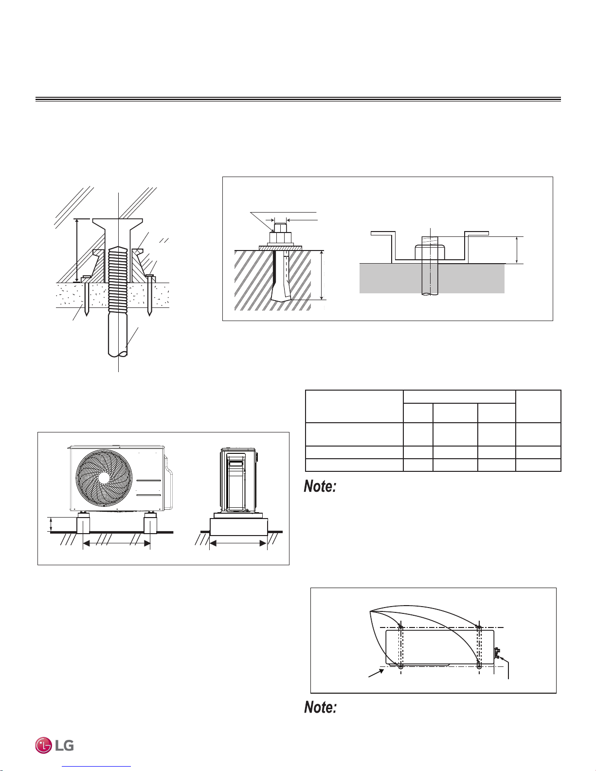
Concrete Platform Specifications
• Concrete foundations must be made of one part cement, two parts sand, and four parts gravel.
• The surface of the foundation must be finished with mortar with rounded edges, and weatherproofed.
Figure 6: Example of Using an Insert for a Hole
in a Reinforced Concrete Beam.
Figure 7: Close up of Bolt Attachment.
Outdoor Unit Mounting
General Installation Guidelines
Outdoor Unit Platform Dimensional Requirements
Figure 8: Single Zone Art Cool Mirror Standard Wall Mount Outdoor
Units.
Bolting the Outdoor Unit to the Platform
1. Ensure that the concrete platform will not degrade easily, and
has enough structural strength to bear the weight of the unit.
2. Include an H-beam support. Firmly attach the corners, otherwise
the support will bend.
3. Use a hexagon nut.
4. Use anti-vibration material.
5. Include enough space around the concrete foundation for condensate drainage.
6. Seal all wiring and piping access holes to prevent insects from
entering the unit.
Due to our policy of continuous product innovation, some specifications may change without notification.
©LG Electronics U.S.A., Inc., Englewood Cliffs, NJ. All rights reserved. “LG” is a registered trademark of LG Corp.
Table 5: Outdoor Unit Foundation Specications.
Foundation (Inches) Leg
Model
LSU090HSV5,
LSU120HSV5
A B C
22 Minimum 4 14-19/32 1/16
Thickness
(Inches)
LSU180HSV5 21-1/2 Minimum 4 14-19/32 3/32
LAU240HSV3 21-1/2 Minimum 4 14-19/32 3/32
Review the specications for eld-supplied pad mounts or brackets to
verify that outdoor dimension requirements are met.
Figure 9: Bolting the Outdoor Unit to the Platform (Piping Location May
Differ Depending on Outdoor Unit Model).
All referenced materials are to be eld-supplied. Images are not to scale.
17
GENERAL INSTALLATION GUIDELINES
Minimum clearance
from ceiling - “A”
More than 4 inches
More than
4 inches
At least 6.5 feet from the floor
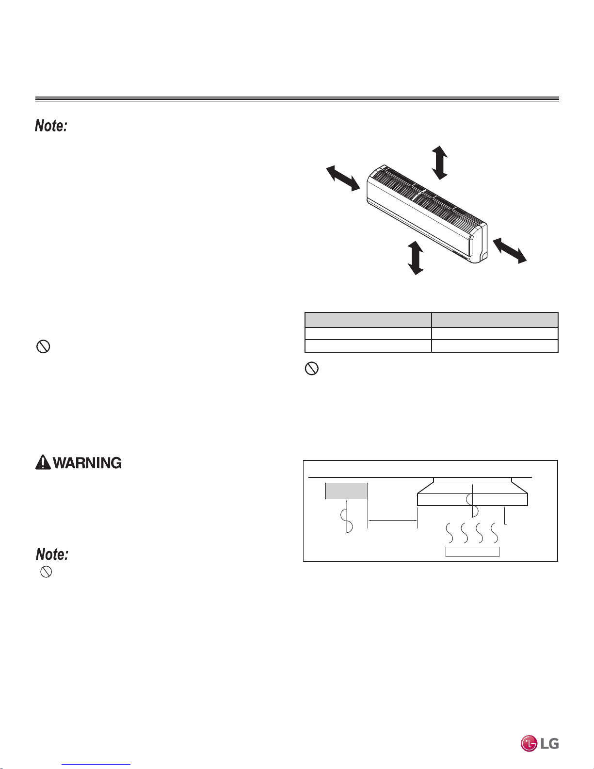
Required Indoor Unit Clearances
Figure 10: Single Zone Art Cool Mirror Wall Mount Indoor Unit Clearance
Follow recommended best practices when choosing an indoor location
for the single zone indoor unit.
Dos
• Follow the table at right for minimum clearance of indoor unit from
the top of the unit to the ceiling.
• Clearance gap between any wall or enclosure and the left or right
side of the unit must be greater than 4 inches. Ensure there is
sufficient maintenance space.
• Unit must be at least 6.5 feet from the floor for adequate clearance.
• Place the unit where drainage can be obtained easily. Condensation drain must be conveniently routed away from the unit.
• Locate the indoor unit in a location where it can be easily connected to the outdoor unit within allowable limits.
• Use a metal detector to locate studs in the walls. Anchor unit
following stud location to prevent damage to the wall.
Dont’s
• Do not install the unit near a heat or steam source, or where consid-
erable amounts of oil, iron powder, or flour are used. (These materials may generate condensate, cause a reduction in heat exchanger
efficiency, or the drain to malfunction. If this is a potential problem,
install a ventilation fan large enough to vent out these materials.)
• Do not install near doorway.
Mirror Wall Mount Installation Manual
• Avoid installing the unit near high-frequency generators.
TM
Requirements.
Table 6: Single Zone Art Cool Mirror Indoor Unit Ceiling Clearances.
“A” Ceiling Clearance (inches) Indoor Unit Model(s)
Dont’s
• Ensure there are no obstacles to air circulation around the unit; keep
proper distances from ceilings, doorways, floor, walls, etc.
• Do not install in an area where operation sound will disturb occupants--place the unit where noise prevention is taken into consideration
Figure 11: Installing Near a Heat or Steam Source.
5 LAN090HSV5, LAN120HSV5
8 LAN180HSV5, LAN240HSV3
The unit must not be installed where sulfuric acid and ammable or
corrosive gases are generated, vented into, or stored. There is risk of
re, explosion, and physical injury or death.
The unit may be damaged, may malfunction, and / or will
not operate as designed if installed in any of the conditions
listed.
Single Zone Art Cool
• Indoor units (IDUs) must not be placed in an environment where the IDUs may be exposed to harmful volatile organic compounds (VOCs)
or in environments where there is improper air make up or supply or inadequate ventilation. If there are concerns about VOCs in the environment where the IDUs are installed, proper air make up or supply and/or adequate ventilation must be provided. Additionally, in buildings
where IDUs will be exposed to VOCs, consider a third party factory-applied epoxy coating to the fan coils for each IDU where the entire coil
is dipped, not sprayed.
• If the unit is installed near a body of water, the installation parts are at risk of corroding. Appropriate anti-corrosion methods must be taken for
the unit and all installation parts.
Installing in an Area Exposed to Unconditioned Air
In some installation applications, areas (floors, walls) in some rooms may be exposed to unconditioned air (room may be above or next to an
unheated garage or storeroom). To countermeasure:
• Verify that carpet is or will be installed (carpet may increase the temperature by three [3] degrees).
• Add insulation between the floor joists.
• Install radiant heat or another type of heating system to the floor.
Due to our policy of continuous product innovation, some specifications may change without notification.
18
©LG Electronics U.S.A., Inc., Englewood Cliffs, NJ. All rights reserved. “LG” is a registered trademark of LG Corp.
Indoor Unit
Include enough
distance
Heat or steam source
Install a ventilation fan
with sufficient capacity
GENERAL INSTALLATION GUIDELINES
(3/16"~5/16")
Indoor
WALL
Outdoor
Bushing
Core Drill
Sleeve
LAN090-120HSV5 Installation Plate
Chassis
Hook
Type "A" Screws
Chassis
Hook
Type "A" Screws
LAN090-120HSV5 Installation Plate
Indoor Unit Mounting
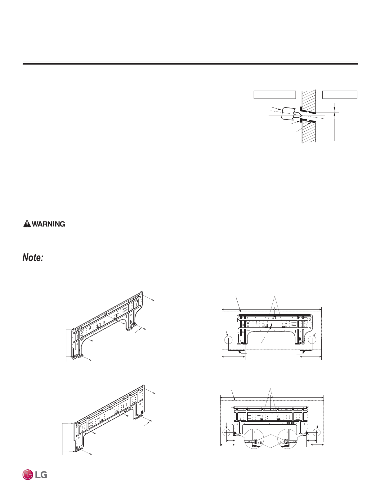
Drilling the Piping Hole in the Wall
Figure 12: Drilling Piping Hole.
Follow all piping clearance recommendations.
1. Using a 2-9/16 inch hole core drill bit, drill a hole at either the right or left side of the
wall mounting, pre-chosen following installation guidelines and application needs.
• The slant of the hole must be 3/16” to 5/16” from level with the slant being upward
on the indoor unit side and downward on the outdoor unit side.
2. Finish off the newly drilled hole as shown with bushing and sleeve covering to prevent damage to the insulation and piping.
Mounting the Installation Plate to the Wall
Follow the procedure below and general best practices when mounting the indoor unit’s installation plate to a wall.
1. The wall mounted indoor unit is shipped with the installation plate attached to its back. To remove, unscrew the one (1) screw that holds
the installation plate to the back of the indoor unit.
2. Align the centerline using a leveling tool. Measure the wall and mark the centerline.
3. Attach the installation plate to the wall following the measurements and marks. Use the type “A” screws that are factory-supplied with the
plate. If mounting the unit on a concrete wall, use field-supplied anchor bolts.
4. Observe all rear piping clearances when drilling into the wall.
• When choosing a location for the wall mount plate, be sure to take into consideration routing of wiring for power outlets within the wall. Con-
tacting wiring can cause serious bodily injury or death.
• Use caution when drilling holes through the walls for the purposes of piping connections. Power wiring can cause serious bodily injury or death.
General Installation Guidelines
Select the location carefully. Unit must be anchored to a strong and solid wall to prevent unnecessary vibration.
Figure 13: Wall Mount Indoor Unit Installation Plates. Figure 14: Wall Mount Indoor Unit Installation Plate Dimensions.
Due to our policy of continuous product innovation, some specifications may change without notification.
©LG Electronics U.S.A., Inc., Englewood Cliffs, NJ. All rights reserved. “LG” is a registered trademark of LG Corp.
Unit Outline
C Type : 16.5 C Type : 16.5
Ø2-9/16"
Left Rear piping
Place a Level on Raised Tab
Installation Plate
C Type
C Type : 5.3C Type : 3.9
LAN180HSV5 Installation Plate
Unit Outline
Ø2-9/16
"
Left Rear piping
3.3
C Type: 5.3
Place a Level on Raised Tab
C Type: 19.4 C Type: 19.8
Measuring Tape
Measuring Tape
Hanger
Ø2-9/16”
Ø2-9/16"
7.66
(Unit : Inch)
Ø2-9/16"
3.3
C Type: 5.9
(Unit : Inch)
Right Rear piping
Right Rear piping
19
GENERAL INSTALLATION GUIDELINES
3
3
3
Indoor Unit Mounting
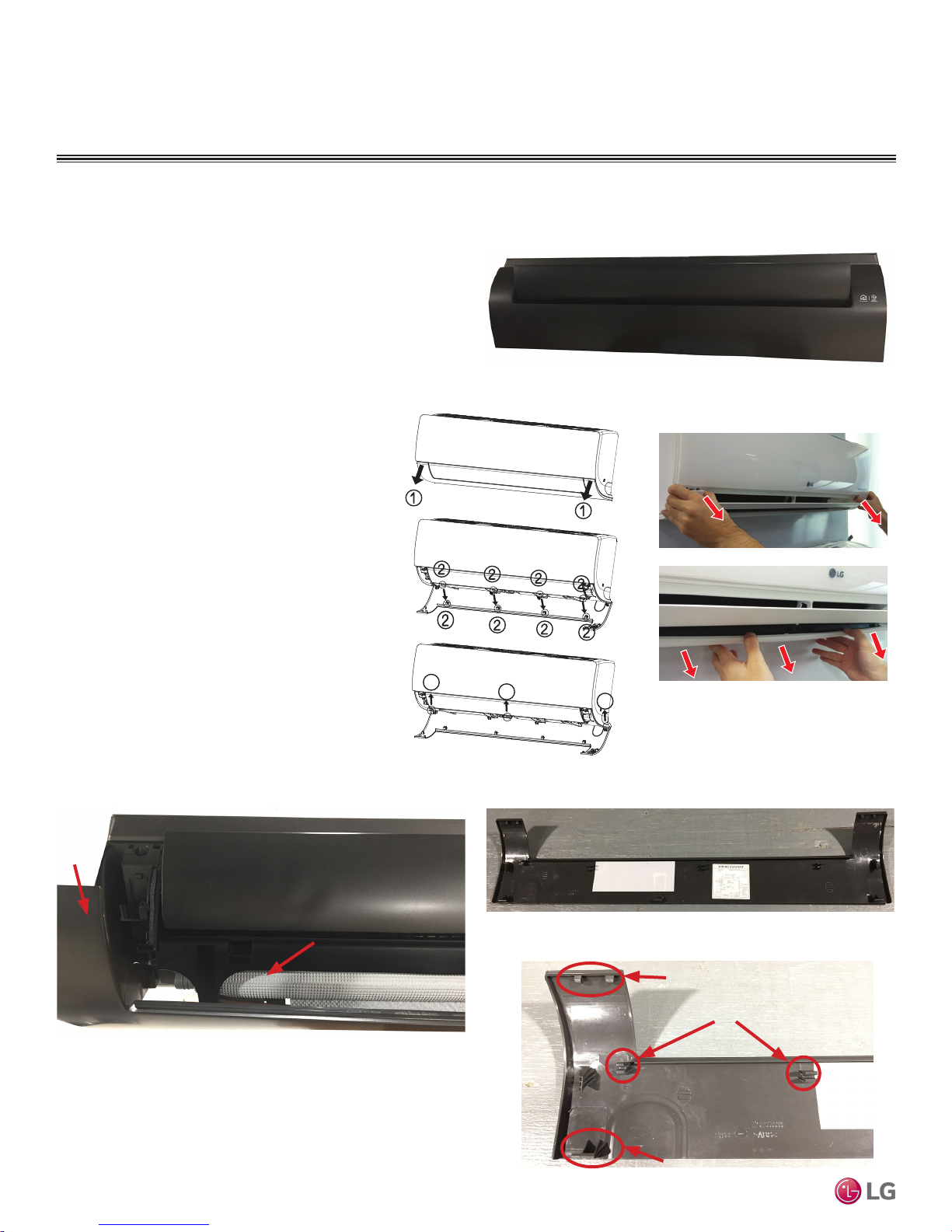
Removing the Indoor Unit Bottom Cover (HSV5)
To access the indoor unit piping port connections,
terminal block, and to make the indoor unit installation
procedure easier, it is recommended that the bottom
cover be removed first.
1. Unsnap the bottom cover at its top left and right
sides (Location 1).
Figure 15: Indoor Unit with the Bottom Cover On (Bottom View; Appearances May Vary Depending on Indoor Unit Model).
2. Unsnap each of the three (3) or four (4) small
C-hooks located in the middle of the bottom cover
(Location 2). Number of C-hooks present depends
on model of indoor unit.
3. Lift the three (3) to four (4) hinges on the bottom
cover up and out of the channels molded to the
left, right, and middle of the indoor unit (Location
3). Number of hinges present depends on model
of indoor unit.
4. Set aside the bottom cover to re-install after all
procedures are complete.
Mirror Wall Mount Installation Manual
TM
Figure 18: Bottom Cover with Top and Middle Unsnapped, Front View
(Appearances May Vary Depending on Indoor Unit Model).
Figure 16: Steps to Removing the
Bottom Cover.
Figure 19: Back of Bottom Cover Completely Removed from Indoor Unit
(Appearances May Vary Depending on Indoor Unit Model).
Figure 17: Removing the Bottom Cover
(Appearances May Vary Depending on
Indoor Unit Model).
Top Left Side of
Bottom Cover
Single Zone Art Cool
Inside of Indoor Unit
20
Due to our policy of continuous product innovation, some specifications may change without notification.
©LG Electronics U.S.A., Inc., Englewood Cliffs, NJ. All rights reserved. “LG” is a registered trademark of LG Corp.
Figure 20: Close Up of Bottom Cover Connections (Appearances May
Vary Depending on Indoor Unit Model).
Top Snaps
C-Hooks
Hinge
GENERAL INSTALLATION GUIDELINES
Type 'C' screw
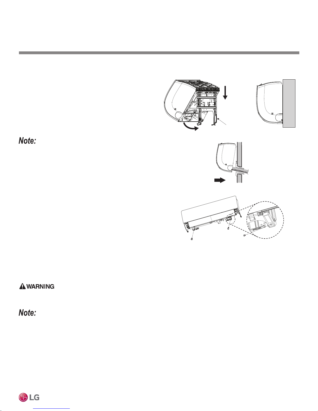
Mounting the Indoor Unit to the Installation Plate
1. Position the indoor unit onto the upper portion of the installation
plate.
2. Engage the hooks at the top of the indoor unit with the upper
edge of the installation plate (number of hooks depends on model
type).
3. Ensure the hooks are properly seated on the installation plate by
shaking the indoor unit left and right.
Figure 21: Attaching the Indoor Unit to the Installation Plate.
Figure 22: Finishing Indoor Unit Installation to the Wall Plate.
Indoor Unit Mounting
Installation Plate
Permanently secure the indoor unit to the wall ONLY AFTER all other
tasks such as Refrigerant Piping Connections, Drain Piping Connections, Electrical Connections, and Final Installation Procedures are
complete. See next page for steps on how to prepare for piping and
electrical connections.
4. Carefully guide the refrigerant piping and drain piping through the
access hole.
5. Push the bottom of indoor unit towards the installation plate to
anchor to the wall.
• Press the lower left and right sides of the unit against the instal-
lation plate until the hooks engage into their slots.
• A clicking sound will be heard as the bottom of the indoor unit
attaches to the installation plate successfully.
• Pay attention to the positioning of the piping through the wall.
6. Finish the installation by completely securing the indoor unit to the installation plate using the factory-supplied two Type “C” screws at the
locations indicated at right.
The indoor unit can fall from the wall if it is not properly installed and secured to the installation plate. Falling indoor units can cause bodily injury or
death.
General Installation Guidelines
• To avoid a gap between the indoor unit and the wall, ensure the screws are correctly and fully secured to the installation plate.
• To prevent condensate from forming due to an inflow of outdoor air, before indoor unit installation is finished, completely seal the piping access
hole in the wall.
Due to our policy of continuous product innovation, some specifications may change without notification.
©LG Electronics U.S.A., Inc., Englewood Cliffs, NJ. All rights reserved. “LG” is a registered trademark of LG Corp.
21
GENERAL INSTALLATION GUIDELINES
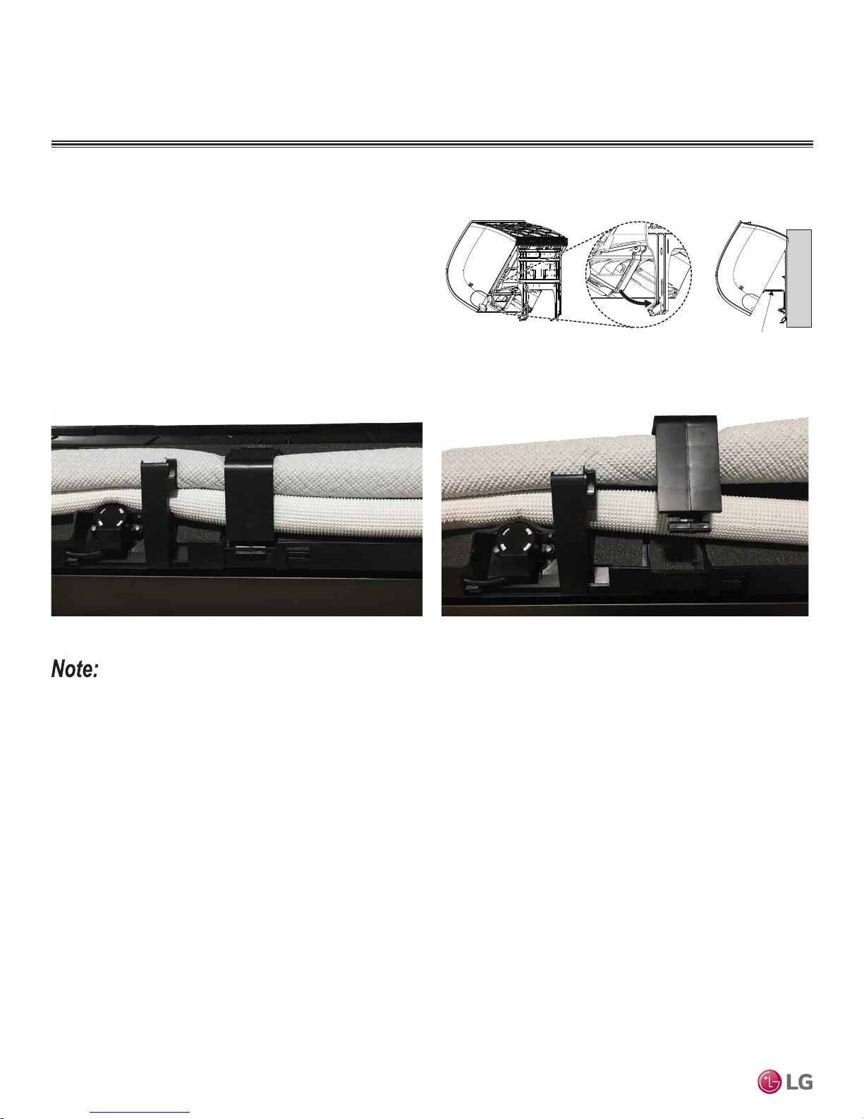
Indoor Unit Mounting
Preparing for Piping / Electrical Connections
1. To prepare the indoor unit for piping and electrical installation,
disengage bottom on indoor unit from installation plate by
reversing Steps 6, 5, and 4 from the previous procedure, if those
procedures have been performed.
2. Unsnap the piping / drain hose holder (L-bracket) out from the
indoor unit chassis. Prop it open between the indoor unit chassis
and installation plate to separate the bottom of the indoor unit
from the wall. This will allow for more working space.
Figure 23: Mounting the Indoor Unit on Installation Plate.
Piping / Drain Hose Holder
Figure 24: L-bracket Closed (Appearances May Vary Depending on
Indoor Unit Model).
Figure 25: L-bracket Open (Appearances May Vary Depending on Indoor
Unit Model).
Mirror Wall Mount Installation Manual
TM
• Go to the Refrigerant Piping Connections section of this manual for information on indoor unit piping connection installation. See also the
Refrigerant Piping Connections section for drain piping installation.
• Go to the Electrical Installation section of this manual for information on electrical wiring to the indoor unit.
• After all Refrigerant Piping and Electrical Connection procedures are complete, snap the L-bracket closed, and secure the indoor unit to the
installation plate as detailed in Steps 5 and 6 in “Mounting the Indoor Unit to the Installation Plate” on the previous page.
Single Zone Art Cool
Due to our policy of continuous product innovation, some specifications may change without notification.
22
©LG Electronics U.S.A., Inc., Englewood Cliffs, NJ. All rights reserved. “LG” is a registered trademark of LG Corp.
REFRIGERANT SAFETY STANDARDS /
Outdoor Unit
Indoor Unit
A
B
Outdoor Unit
Indoor Unit
A
B
DEVICE CONNECTION LIMITATIONS
Refrigerant Safety Standards
ASHRAE Standards 15-2010 and 34-2010 address refrigerant safety and the maximum allowable concentration of refrigerant in an occupied
space. Refrigerant will dissipate into the atmosphere, but a certain volume of air is required to safely dissipate the refrigerant. For R410A
refrigerant, the maximum allowable concentration of refrigerant is 26 lbs./1,000 cubic feet (Addendum L modified the RCL to 26) of occupied
spaces. Buildings with 24-hour occupancy are allowed half of that concentration.
If a single zone system develops a refrigerant leak, the entire refrigerant charge of the system will dump into the area where the leak occurs.
To meet ASHRAE Standards 15 and 34, the smallest room volume on the system must be calculated and compared to the maximum allowable concentration. Also consult state and local codes in regards to refrigerant safety.
General Refrigerant Piping System Information
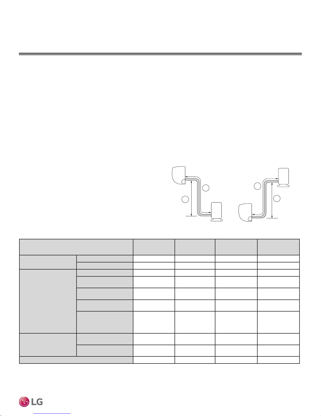
Device Connection Limitations
A single-zone system consists of one outdoor unit and one indoor
unit. One of the most critical elements of a single-zone system is the
refrigerant piping. If the connection piping is not within allowable limits, there will be reliability, performance, noise, and vibration issues.
See the table below for pipe length limits that must be followed in the
design of a Single Zone Art Cool Mirror Wall Mount refrigerant pipe
system. For information on additional refrigerant charge necessary
for longer piping lengths, refer to Table 19 in the “Refrigerant Trim
Charge” section.
Table 7: Single Zone Art Cool Mirror Refrigerant Piping System Limitations.
(ELF = Equivalent Length
(All Elevation Limitations
are Measured in Actual
Additional Refrigerant Needed (oz/ft)
Pipe Sizes
Pipe Length
of pipe in Feet)
Elevation
Feet)
Model Numbers
Vapor
Liquid
Standard Piping Length
Piping Length with No
Additional Refrigerant
Longest total equivalent
piping length
Shortest total equivalent
piping length
Distance between fittings
and indoor units or
units
If outdoor unit is above
indoor unit
If outdoor unit is below
indoor unit
outdoor
Figure 26: Single Zone Art Cool Mirror Wall Mount System Layout.
LA090HSV5
(LAN090HSV5/
LSU090HSV5)
Ø3/8 Ø3/8 Ø5/8 Ø5/8
Ø1/4 Ø1/4 Ø3/8 Ø3/8
24.6 24.6 24.6 24.6
41 41 24.6 24.6
82 82 114.8 98.4
9.8 9.8 9.8 9.8
≥20 inches ≥20 inches ≥20 inches ≥20 inches
49.2 49.2 49.2 49.2
49.2 49.2 49.2 49.2
0.22 0.22 0.38 0.38
LA120HSV5
(LAN120HSV5/
LSU120HSV5)
LA180HSV5
(LAN180HSV5/
LSU180HSV5)
LA240HSV3
(LAN240HSV3/
LAU240HSV3)
Due to our policy of continuous product innovation, some specications may change without notication.
© LG Electr onics U.S.A., Inc., Englewood Cli ffs, NJ. All ri ghts reserved . “LG” is a register ed trademark of LG C orp.
23
 Loading...