

LG LAN181CNW, LAU181CNW, LA180CPI, LA180CPO User Manual

website http://www.lgservice.com
LG
Room Air Conditioner
SERVICE MANUAL
MODELS: LAN181CNW(ASNC183VML3)
LAU181CNW(ASUC183VML3)
LA180CPI (ASNC183VML3)
LG
LA180CPO (ASUC183VML3)
CAUTION
• BEFORE SERVICING THE UNIT, READ THE SAFETY
PRECAUTIONS IN THIS MANUAL.
• ONLY FOR AUTHORIZED SERVICE PERSONNEL.

2 Room Air Conditioner
Details of 2006 LG Model Name.................................................................................................... 3
Safety Precautions......................................................................................................................... 4
Functions...................................................................................................................................... 10
Product References .................................................................................................................... 12
Dimensions................................................................................................................................... 13
Refrigeration Cycle Diagram....................................................................................................... 15
Wiring Diagram............................................................................................................................. 16
Operation Details ......................................................................................................................... 17
Display Function.......................................................................................................................... 23
Self-diagnosis Function ...............................................................................................................23
Introduction...................................................................................................................................24
Installation.................................................................................................................................... 25
Operation...................................................................................................................................... 42
Disassembly of the parts (Indoor Unit)...................................................................................... 43
2-way, 3-way Valve ....................................................................................................................... 46
Cycle Troubleshooting Guide ..................................................................................................... 54
Electronic Control Device............................................................................................................ 64
Schematic Diagram...................................................................................................................... 67
Exploded View and Replacement Parts List.............................................................................. 69
Air Conditioner Service Manual
TABLE OF CONTENTS
Service Manual 3
Details of 2006 LG Model Name
12
Code Type Code of Model Meaning
1 Producing Center/ A~Z
L: ChangWon R22, A: ChangWon R410A, C: ChangWon
R407C
Refrigerant
2 Type of Air conditioner A~Z S: Split Type Air conditioner
3 Cooling/Heating A~Z C: C/O, H: H/P, X: C/O + E/H, Z: H/P + E/H
4,5 Capacity(Btu/h) 1~9 Cooling/Heating Capacity
Ex. "09" ➔ 9,000Btu/h
6 Electric Range 1~9 Electric Standard
1 ➔ 115V/60Hz 6 ➔ 220~240V/50Hz
2 ➔ 220V/60Hz 7 ➔ 110V, 50/60Hz
3 ➔ 208~230V/60Hz 8 ➔ 380~415V/50Hz
5 ➔ 200~220V/50Hz 9 ➔ 380~415V/60Hz
7 Chassis A~Z Name of tool of unit
8 Color A~Z R: Mirror B: Blue N: Walut
W: White M: Metal C: Cherry
9 Function A~Z
10 Serial No. 0~9
-
Basic A
Basic + 4Way B
Plasma Filter C
Plasma Filter + 4Way D
Tele + LED + 4Way E
Tele + LCD + Plasma F + 4Way F
Tele Multi + LCD + Plasma F + 4Way G
Low A + Plasma F H
Low A + Plasma F + 4Way J
Plasma F + 4Way + Oxygen Generator K
A/change + Plasma F L
A/change + Plasma F + 4Way M
345678910
Details of 2006 LG Model Name
4 Room Air Conditioner
Safety Precautions
Safety Precautions
To prevent injury to the user or other people and property damage, the following instructions must
be followed.
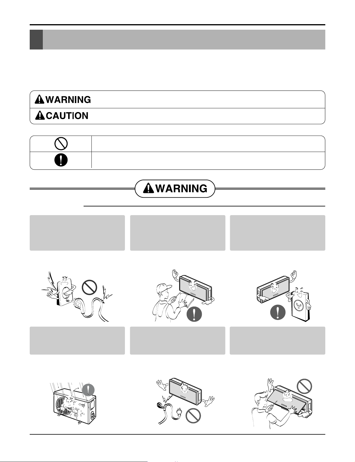
■ Incorrect operation due to ignoring instruction will cause harm or damage. The seriousness is
classified by the following indications.
■ Meanings of symbols used in this manual are as shown below.
This symbol indicates the possibility of death or serious injury.
This symbol indicates the possibility of injury or damage to properties only.
Be sure not to do.
Be sure to follow the instruction.
■ Installation
Do not use damaged power
cords, plugs, or a loose socket.
• There is risk of fire or electric
shock.
For electrical work, contact the
dealer, seller, a qualified electrician, or an Authorized Service
Center.
• There is risk of fire or electric
shock.
Always use the power plug and
socket with the ground terminal.
• There is risk of electric shock.
Install the panel and the cover of
control box securely.
• There is risk of fire or electric
shock.
Do not modify or extend the
power cord.
• There is risk of fire or electric
shock.
Do not install, remove, or reinstall the unit by yourself (customer).
• There is risk of fire, electric
shock, explosion or injury.
Service Manual 5
Safety Precautions
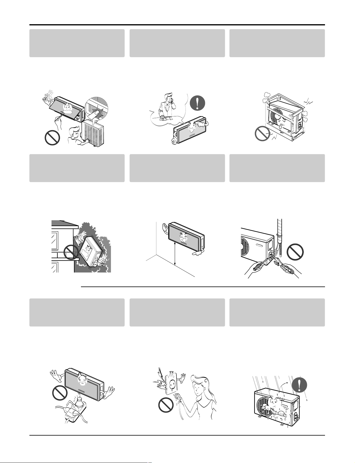
■ Operation
Be cautious when unpacking
and installing the product.
• Shape edges could cause injury.
Be especially careful of the sharp
edges.
For installation, always contact
the dealer or an Authorized Service Center.
• There is risk of fire, electric
shock, explosion, or injury.
Do not install the product on a
defective installation stand.
• It may cause injury, accident, or
damage to the product.
Be sure the installation area
does not deteriorate with age.
• If the base collapses, the air conditioner could fall with it, causing
property damage, product failure,
and personal injury.
Install the indoor unit on the
wall where the height from the
floors more then 8ft(2.4m)
• There are sharp moving parts
that could cause personal injury.
Do not handle the pipe by yourself(customer)
• High-Pressure refrigent may
cause personal injury.
Use a dedicated outlet for this
appliance.
• There is risk of fire or electric
shock.
Grasp the plug to remove the
cord from the outlet. Do not
touch it with wet hands.
• There is risk of fire or electric
shock.
Do not allow water to run into
electric part.
• There is risk of fire, failure of the
product, and/or electric shock.
8ft(2.4m)
6 Room Air Conditioner
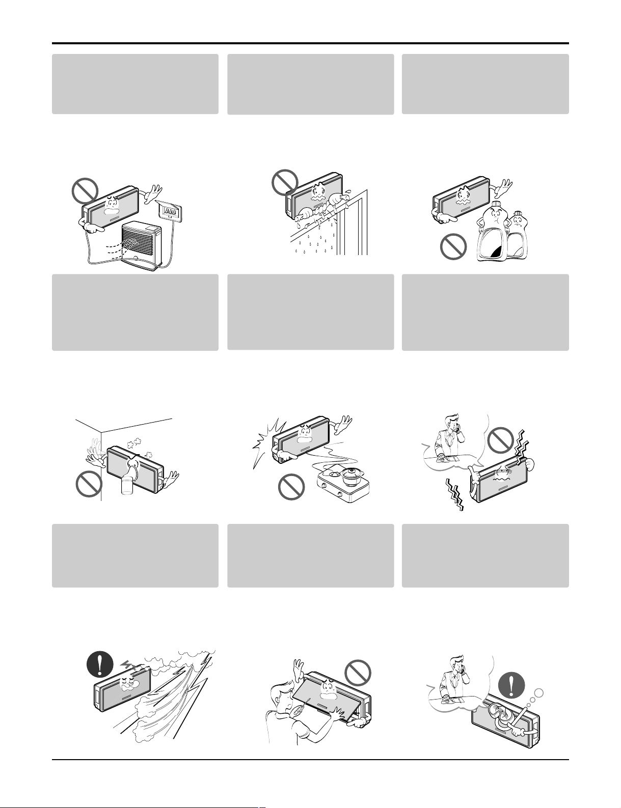
Safety Precautions
Do not place a heater or other
appliances near the power
cable.
•
There is risk of fire, failure of the
product, and/or electric shock.
Do not let the air conditioner run
for a long time when the humidity is very high and a door or a
window is left open.
• Moisture may condense and wet
or damage furnishings.
Do not store of use flammable
gas or combustibles near the air
conditioner.
• There is risk of fire or product failure.
Do not use the product in a
tightly closed space for a long
time.
• Oxygen deficiency could occur.
• Some ventilation by opeing window is necessary for the fresh air.
When flammable gas leaks, turn off
the gas and open a window for ventilation before turning the product on.
Do not use the telephone or turn
switches on or off.
• There is risk of explosion or fire.
Unplug the unit if strange
sounds odors or smoke comes
from it.
•
There is risk of fireproduct failure
and/or electric shock.
Stop operation and close any
window in storm or hurricane.
before the hurricane arrives.
• There is risk of property damage,
failure of product, or electric
shock.
Do not open the inlet grill of the
product during operation. (Do
not touch the electrostatic filter,
if the unit is so equipped.)
• There is risk of physical injury,
electric shock, or product.
When the product is soaked
(flooded or submerged), contact
an Authorized Service Center.
• There is risk of electrical shock.
Thinner
Wax

Service Manual 7
Safety Precautions
Ventilate the product from time
to time when operating it together with a stove, etc.
• There is risk of fire or electrical
shock.
Unplug the appliance before
performing cleaning or maintenance.
• There is risk of electric shock.
When the product is not be used
for a long time disconnect the
power supply plug or turn off
the breaker.
• There is risk of product damage
or failure, or unintended operation.
Take care to ensure that nobody
could step on or fall onto the
outdoor unit.
• There could result in personal
injury and product damage.
Do not insert hands or other
objects through the air inlet or
outlet while the air conditioner
is plugged in.
• There are sharp and moving
parts that could cause personal
injury.
Always check for gas(refrigerant) leakage after installation or
repair of product.
• Low refrigerant levels may cause
product failure.
Install the drain hose to ensure
that water is drained away properly.
• A bad connection may cause
water leakage.
Keep level even when installing
the product.
• To avoid vibration or water leakage.
Do not install the product where
the noise or hot air from the outdoor unit could damage the
neighborhoods.
• It may cause a problem for your
neighbors.
■ Installation
90˚

8 Room Air Conditioner
Safety Precautions
■ Operation
Use two or more people to lift
and transport the air conditioner
• Avoid personal injury.
Do not install the product where
it will be exposed to sea wind
(salt spray) directly.
• It may cause corrosion in the
product. Corrosion, particularly
on the condenser and evaporator
fins, could cause product malfunction or inefficient operation.
Do not direct airflow at room
occupants.
• This could damage your health.
Do not use the product for special
purposes, such as preserving
foods, works of art, etc. It is a
consumer air conditioner, not a
precision refrigeration system.
• There is risk of damage or loss of
property.
Do not block the inlet or outlet
of air flow.
• It may cause product failure.
Use a soft cloth to clean.
Do not use harsh detergents,
solvents, etc.
• There is risk of fire, electric shock
or damage to the plastic parts of
the product.
Do not touch the metal parts of
the product when removing the
air filter. They are very sharp!
• There is risk of personal injury.
Do not step on or put anything
on the product. (outdoor unit)
• There is risk of personal injury
and failure of product.
Always insert the filter securely.
Clean the filter every two weeks
or more often if necessary.
• A dirty filter reduces the efficiency of the air conditioner and

Service Manual 9
Safety Precautions
Do not drink the water drained
from the unit.
• It is not sanitary and could cause
serious health issues.
Use a firm stool or ladder when
cleaning or maintaining the air
conditioner.
• Be careful and avoid personal
injury.
Replace all the batteries in the
remote.
• There is risk of fire or explosion.
Do not recharge or disassemble the batteries. Do
not dispose of batteries in a fire.
• They may burn or explode.
If the liquid from the batteries gets onto your skin
or clothes, wash it well with clean water. Do not
use the remote if the batteries have leaked.
• The chemicals in batteries could cause burns or other health hazards.
■ Disuse

10 Room Air Conditioner
Functions
• Room temperature sensor. (THERMISTOR)
• Maintains the room temperature in accordance with the Setting Temp.
• Indoor fan is delayed for 5 sec at the starting.
• Restarting is inhibited for approx. 3 minutes.
• High, Med, Low, CHAOS
• Intermittent operation of fan at low speed.
• The fan is switched to low(Cooling), med(Heating) speed.
• The unit will be stopped after 1, 2, 3, 4, 5, 6, 7 hours.
• The fan is switched to intermittent or irregular operation
•
The fan speed is automatically switched from high to low speed.
• The louver can be set at the desired position or swing
up and down automatically.
Indoor Unit
Operation ON/OFF by Remote controller
Sensing the Room Temperature
Room temperature control
Starting Current Control
Time Delay Safety Control
Indoor Fan Speed Control
Operation indication Lamps (LED)
Soft Dry Operation Mode
• Both the indoor and outdoor fan stops during defrosting.
• The indoor fan stops until the
evaporator pipe temperature will be reached
at 28°C.
Sleep Mode Auto Control
Natural Air Control by CHAOS Logic
Airflow Direction Control
Defrost(Deice) control (Heating)
Hot-start Control (Heating)
Signal Receptor
Receives the signals from the remote control.(Signal receiving sound: two short beeps or one long beep.)
Operation Indication Lamps
On/Off : Lights up during the system operation.
Sleep Mode : Lights up during Sleep Mode Auto operation.
Timer : Lights up during Timer operation.
Defrost Mode : Lights up during Defrost Mode or
Hot Start operation.(Heat pump model only)
Outdoor unit operation : Lights up during outdoor unit operation.
(Cooling model only)
Functions
Operation indication lamps

Service Manual 11
Functions
Healthy Dehumidification Operation Mode.
( )
Remote Control
Operation ON/OFF
Reset
Operation Mode Selection
Temperature Setting
Timer Selection
Timer Setting
JET COOL
Timer Cancel
Sleep Operation
Airflow Direction Control
(Cooling
model only)
(Heating
model only)
TEMPERATURE
LOW HIGH
Cooling Operation Mode.( )
Heating Operation Mode.( )
Auto Operation Mode.( )
Air Circulation
°C To °F Swiching Button
Room, Temperature Checking
Setting the Time or Timer
Fan Speed Selection
(Low) (Med) (High)
ON
OFF
CANCEL
SET
2nd F
°C/°F
: (Low:11°C High:39°C)
: OFF, ON, OFF ON
: Cancel Sleep Mode, Timer ON or Timer OFF
: 1, 2, 3, 4, 5, 6, 7, Off Timer
: Fan Operates without cooling or heating.
Cooling
Down to 18°C
Up to 30°C
Heating
Down to 16°C
Up to 30°C
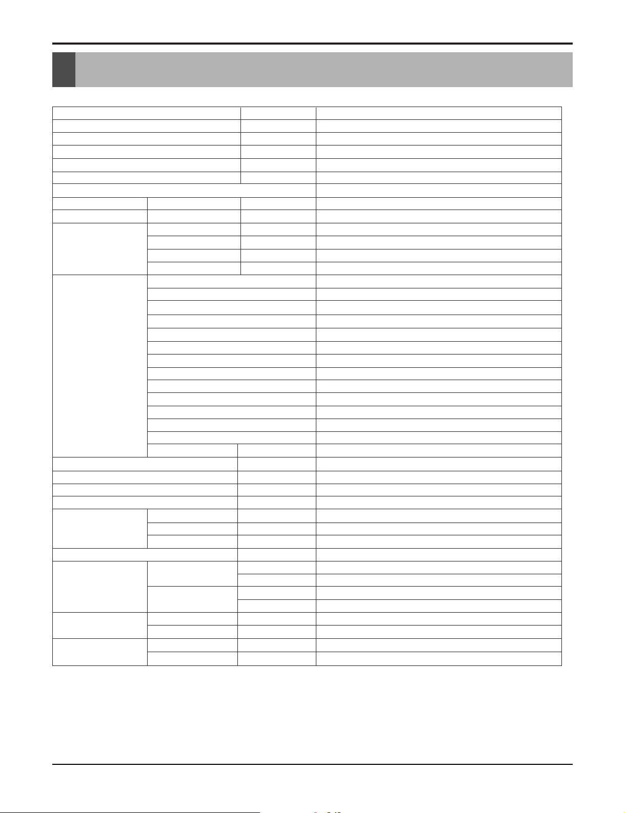
Product References
Product References
Items Unit
Power Supply ø, V, Hz 1, 208/230, 60
Cooling Capacity BTU/h 17 800/18 000
Input W 2,000/2,000
Running Current A 9.8/8.9
COMP. Locked Rotor AMP. A 25*2
S.E.E.R 13
Air Circulation m3/min(cfm) 13(460)
Moisture Removal l/h(pts/hr) 2.5(5.3)
Noise Level Indoor, High dB(A)±3 44
(Sound Med dB(A)±3 40
Pressure, 1m) Low dB(A)±3 36
Outdoor, Max dB(A)±3 55
Features Temperature Control Thermistor
Air Deflection 4-way
Steps, Fan/Cool 3/4
Airflow Direction Control(up&down) Auto
Airflow Direction Control(left&right) Auto
Remocon Type Wireless LCD
Setting Temperature Range, Cooling Mode 64~86°F(18~30°C)
Temperature Increment 2°F(1°C)
Auto Operation(electronic control) Yes
Self Diagnosis Yes
Timer 24hr, On/Off
Sleep Operation Yes
Healthy Dehumidification Mode Yes
Restart Delay minutes 3
Refrigerant(R-410A) Charge g(oz) 900(31.8)
Power cord AWG #: P*mm
Fuse or breaker Capacity A 20
Connecting Cable AWG #: P*mm
Connecting Tube Liquid Side mm(in) 6.35(1/4)
(ø. Socket Flare) Gas Side mm(in) 12.7(1/2)
Length, std m(ft) 7.5(25)
Additional Drain Hose(Outer Dia.) mm(in) 19(3/4)
Dimensions Indoor mm 928*522*147
(WxHxD) in 361/2*2019/32*525/32
Outdoor mm 870*655*320
in 341/4*2513/16*125/8
Net Weight Indoor kg(lbs) 17(37.5)
Outdoor kg(lbs) 68(149.9)
Gross Weight Indoor kg(lbs) 19(41.9)
Outdoor kg(lbs) 71(156.5)
LA*181CNW(AS-C183VML3)/LA180CP* (AS-C183VML3)
2
2
14:3*2.5
18:4*0.75
NOTE: Please refer to Label Quality on the product since this specification may be changed for improving
performance
12 Room Air Conditioner

Service Manual 13
Dimensions
522
928
147
Pipe Hole Fix Hole
MODEL
DIM Unit
W mm(inch) 928(36.5)
H mm(inch) 522(20.6)
D mm(inch) 147(5.8)
Indoor Unit
Dimensions
Indoor Unit
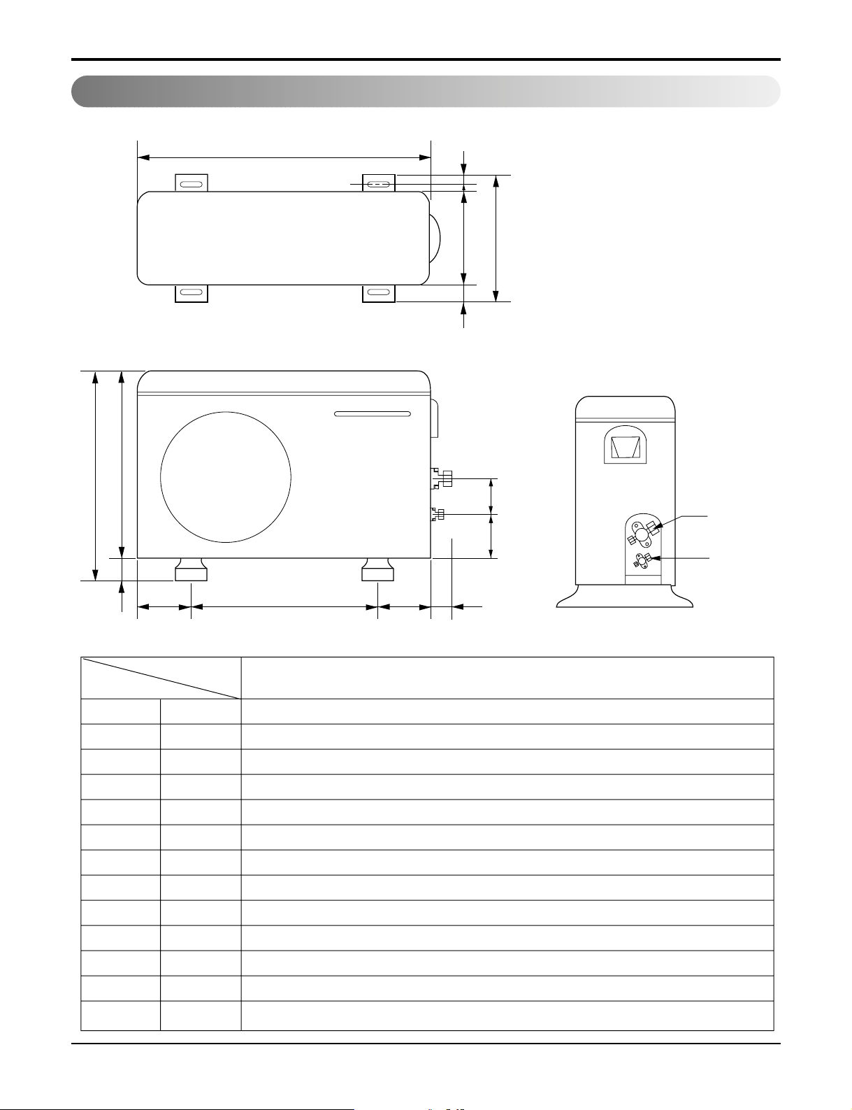
14 Room Air Conditioner
Dimensions
W
L6 L5 L7 L8
D
L1
L2
L9L10
L3L4
H
Gas side
3-way valve
Liquid side
2-way valve
MODEL
OUTDOOR UNIT
DIM
W mm(inch) 870(34.3)
H mm(inch) 655(25.8)
D mm(inch) 320(12.6)
L1 mm(inch) 370(14.6)
L2 mm(inch) 25(1.0)
L3 mm(inch) 630(24.8)
L4 mm(inch) 25(1.0)
L5 mm(inch) 546(21.5)
L6 mm(inch) 162(6.4)
L7 mm(inch) 162(6.4)
L8 mm(inch) 54(2.1)
L9 mm(inch) 74.5(2.9)
L10 mm(inch) 79(3.1)
Outdoor Unit
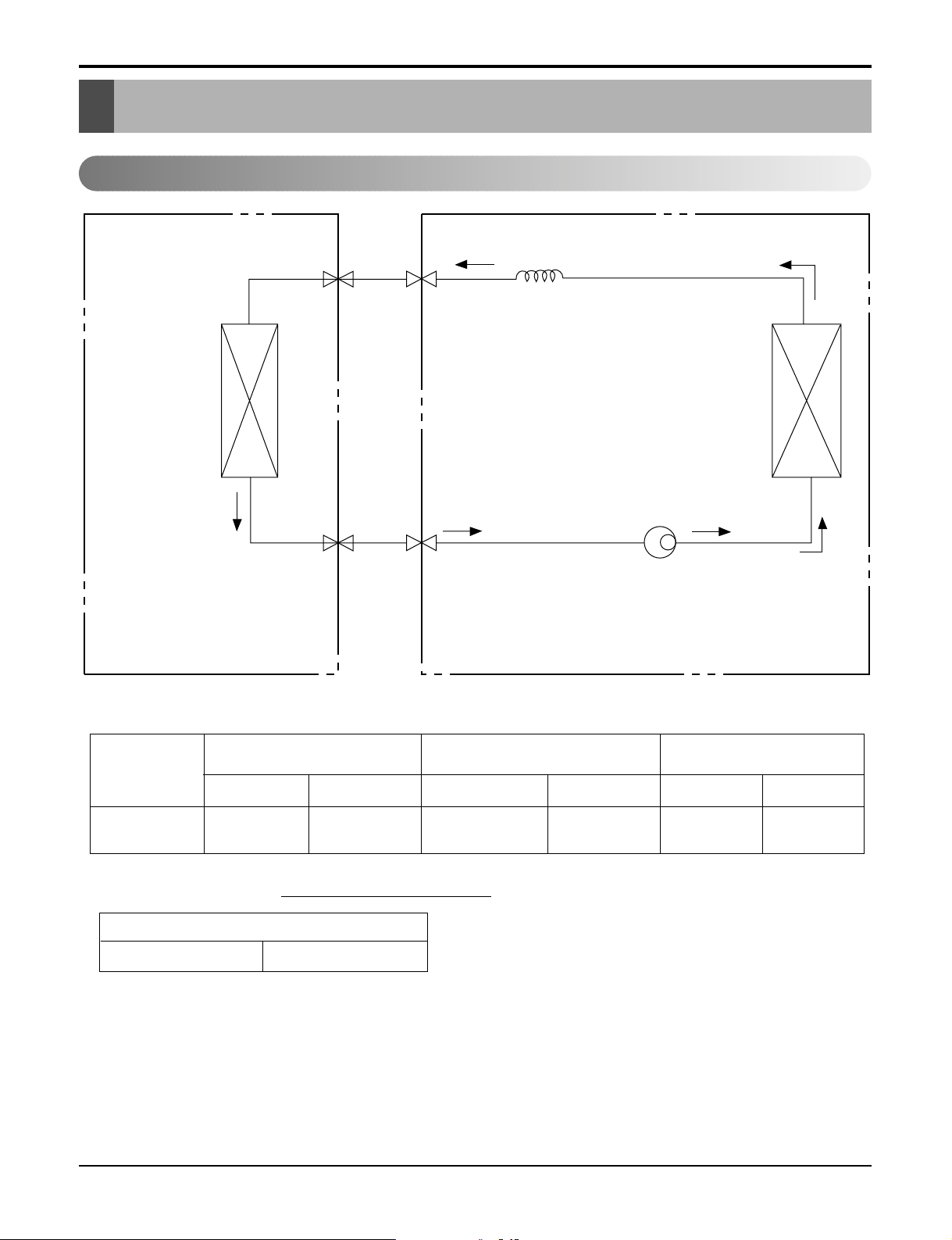
Service Manual 15
Refrigeration Cycle Diagram
For installation over rated, *a proper quantity of refrigerant should be added for each meter.
Ex) 18K: When installed at a distance of 30m, 450g of
refrigerant should be added.
(30-7.5) x 20g = 450g
INDOOR UNIT
HEAT
EXCHANGER
(EVAPORATOR)
HEAT
EXCHANGER
(CONDENSER)
COMPRESSOR
GAS SIDE
CAPILLARY TUBE
LIQUID SIDE
OUTDOOR UNIT
MODEL
18K
(Cooling Only)
Pipe size(Diameter:ø) Piping length Elevation
Gas Liquid Rated Max Rated Max
1/2" 1/4" 7.5m(24.6ft) 30m(98.4ft) 5m(16ft) 15m(49ft)
a proper quantity of refrigerant
18K 20g
Refrigeration Cycle Diagram
Cooling Only Models

16 Room Air Conditioner
Wiring Diagram
18K (Cooling Only Models)
Wiring Diagram
Indoor Unit
Outdoor Unit

Service Manual 17
Operation Details
• DISPLAY
1) C/O Model
Operation Indicator
• ON while in appliance operation, OFF while in appliance pause.
• Flashing while in disconnection or short in Thermistor. (3 sec off / 0.5 sec on)
Sleep Timer Indicator
• ON while in sleep timer mode, OFF when sleep timer cancel or appliance operation pause.
Timer Indicator
• ON while in timer mode (on/off), OFF when timer mode is completed or canceled.
Comp. Running Incidator
• While in appliance operation, ON while in outdoor unit compressor running, OFF while in compressor off.
2) H/P Model
Operation Indicator
• ON while in appliance operation, OFF while in appliance pause.
• Flashing while in disconnection or short in Thermistor. (3 sec off / 0.5 sec on)
Sleep Timer Indicator
• ON while in sleep timer mode, OFF when sleep timer cancel or appliance operation pause.
Timer Indicator
• ON while in timer mode (on/off), OFF when timer mode is completed or canceled.
Defrost Indicator
• OFF except when hot start during heating mode operation or while in defrost control.
■ Cooling Mode Operation
• When the intake air temperature reaches 0.5°C below the setting temp, the compressor and the outdoor fan
stop.
• When it reaches 0.5°C above the setting temp, they start to operate again.
Compressor ON Temp ➲ Setting Temp+0.5°C
Compressor OFF Temp ➲ Setting Temp-0.5°C
• While in compressor running, operating with the airflow speed set by the remote control. While in compressor
not running, operating with the low airflow speed regardless of the setting.
■ Healthy Dehumidification Mode
• When the dehumidification operation input by the remote control is received, the intake air temperature is
detected and the setting temp is automatically set according to the intake air temperature.
26°C ≤ Intake Air Temp ➲ 25°C
24°C ≤ Intake Intake Air Temp<26°C ➲ Intake Air Temp-1°C
18°C ≤ Intake Intake Air Temp<24°C ➲ Intake Air Temp-0.5°C
Intake Air Temp<18°C ➲ 18°C
Operation Details
MAIN UNIT FUNCTION

18 Room Air Conditioner
Operation Details
• While in compressor off, the indoor f an repeats low airflow speed and pause.
• While the intake air temp is between compressor on temp. and compressor off temp., 10-min dehumidifica-
tion operation and 4-min compressor off repeat.
Compressor ON Temp. ➲ Setting Temp+0.5°C
Compressor OFF Temp. ➲ Setting Temp-0.5°C
• In 10-min dehumidification operation, the indoor fan operates with the low airflow speed.
■ Heating Mode Operation
• When the intake air temp reaches +3°…above the setting temp, the compressor is turned off. When below
the setting temp, the compressor is turned on.
Compressor ON Temp. ➲ Setting Temp.
Compressor OFF Temp. ➲ Setting Temp.+3°C
• While in compressor on, the indoor fan is off when the indoor pipe temp. is below 20°C, when above 28°C , it
operates with the low or setting airflow speed. When the indoor pipe temp is between 20°C and 28°C, it operates with Super-Low(while in sleep mode, with the medium airflow speed).
• While in compressor off, the indoor fan is off when the indoor pipe temp is below 33°C, when above 35°C , it
operates with the low airflow speed.
• If overloaded while in heating mode operation, in order to prevent the compressor from OLP operation, the
outdoor fan is turned on/off according to the indoor pipe temp.
• While in defrost control, both of the indoor and outdoor fans are turned off.
■ Defrost Control
• While in heating mode operation in order to protect the evaporator pipe of the outdoor unit from freezing,
reversed to cooling cycle to defrost the evaporator pipe of the outdoor unit.
• After 40 min heating mode operation, at 4 min interval, whether to carry out defrost control or not and the time
of defrost control are determined according to the following conditions.
1) While in heating mode operation, the maximum of the indoor pipe temperature is measured and it is com-
pared with the present indoor pipe temperature to get the difference of the indoor pipe temperatures (=the
maximum temperature of indoor pipe ? the present temperature of indoor pipe), according to which, whether
to carry out defrost control or not is determined.
2) According to the need of defrost control shown above and the elapsed time of heating mode operation at that
moment, the defrost control time is determined.
3) When the determined time of defrost control is below 7 min, heating mode operation continues without carry-
ing out defrost control. According to the procedure stated above, the determination is made again. When the
defrost control time is 7 min or longer, defrost control is then carried out.
• While in defrost control, the minimum temp of the indoor pipe is measured and it is compared with the present
temp of the indoor pipe to get the difference of the indoor pipe temperatures (=the present temperature of the
indoor pipe ? the minimum temperature of the indoor pipe). When the difference is 5°C or higher, defrost control is completed and heating mode operation is carried out.
• While in defrost control, if the defrost time determined before the start of defrost control is completed, defrost
control stops and heating mode operation is carried out regardless of the above condition.
• When the indoor pipe temp is 42°C or above, defrost control is not carried out even if the condition is one of
the defrost conditions above.
• While in defrost control, the compressor is on and the indoor fan, the outdoor fan, and the 4 way valve are off.

Service Manual 19
Operation Details
■ Fuzzy Operation (C/O Model)
• According to the temperature set by Fuzzy rule, when the intake air temp is 0.5°C or more below the setting
temp, the compressor is turned off. When 0.5°C or more above the setting temp, the compressor is turned on.
Compressor ON Temp ➲ Setting Temp + 0.5°C
Compressor OFF Temp ➲ Setting Temp + 0.5°C
• At the beginning of Fuzzy mode operation, the setting temperature is automatically selected according to the
intake air temp at that time.
26°C ≤ Intake Air Temp ➲ 25°C
24°C ≤ Intake Air Temp < 26°C ➲ Intake Air Temp + 1°C
22°C ≤ Intake Air Temp < 24°C ➲ Intake Air Temp + 0.5°C
18°C ≤ Intake Air Temp < 22°C ➲ Intake Air Temp
Intake Air Temp<18°C ➲ 18°C
• When the Fuzzy key (Temperature Control key) is input after the initial setting temperature is selected, the
Fuzzy key value and the intake air temperature at that time are compared to select the setting temperature
automatically according to the Fuzzy rule.
• While in Fuzzy operation, the airflow speed of the indoor fan is automatically selected according to the
temperature.
■ Fuzzy Operation (H/P Model)
• When any of operation mode is not selected like the moment of the power on or when 3 hrs has passed since
the operation off, the operation mode is selected.
• When determining the operation mode, the compressor, the outdoor fan, and the 4 way valve are off and only
the indoor fan is operated for 15 seconds. Then an operation mode is selected according to the intake air
temp at that moment as follows.
24°C ≤ Inatake Air Temp ➲ Fuzzy Operation for Cooling
21°C ≤ Inatake Air Temp<24°C ➲ Fuzzy Operation for Dehumidification
Inatake Air Temp<21°C ➲ Fuzzy Operation for Heating
• If any of the operation modes among cooling / dehumidification / heating mode operations is carried out for 10
sec or longer before Fuzzy operation, the mode before Fuzzy operation is operated.
1) Fuzzy Operation for Cooling
• According to the setting temperature selected by Fuzzy rule, when the intake air temp is 0.5°C or more below
the setting temp, the compressor is turned off. When 0.5°C or more above the setting temp, the compressor
is turned on.
Compressor ON Temp ➲ Setting Temp +0.5°C
Compressor OFF Temp ➲ Setting Temp + 0.5°C
• At the beginning of Fuzzy mode operation, the setting temperature is automatically selected according to the
intake air temp at that time.
26°C≤ Intake Air Temp ➲ 25°C
24°C≤ Intake Air Temp<26°C ➲ Intake Air Temp + 1°C
22°C≤ Intake Air Temp<24°C ➲ Intake Air Temp + 0.5°C
18°C≤ Intake Air Temp<22°C ➲ Intake Air Temp
Intake Air Temp<18°C ➲ 18°C
• When the Fuzzy key (Temperature Control key) is input after the initial setting temperature is selected, the
Fuzzy key value and the intake air temperature at that time are compared to select the setting temperature
automatically according to the Fuzzy rule.
• While in Fuzzy operation, the airflow speed of the indoor fan is automatically selected according to the temperature.

20 Room Air Conditioner
Operation Details
2) Fuzzy Operation for Dehumidification
• According to the setting temperature selected by Fuzzy rule, when the intake air temp is 0.5°C or more below
the setting temp, the compressor is turned off. When 0.5°C or more above the setting temp, the compressor
is turned on.
Compressor ON Temp ➲ Setting Temp + 0.5°C
Compressor OFF Temp ➲ Setting Temp+0.5°C
• At the beginning of Fuzzy mode operation, the setting temperature is automatically selected according to the
intake air temp at that time.
26°C ≤ Intake Air Temp ➲ 25°C
24°C ≤ Intake Air Temp<26°C ➲ Intake Air Temp+1°C
22°C ≤ Intake Air Temp<24°C ➲ Intake Air Temp+0.5°C
18°C ≤ Intake Air Temp<22°C ➲ Intake Air Temp
Intake Air Temp<18°C ➲ 18°C
• When the Fuzzy key (Temperature Control key) is input after the initial setting temperature is selected, the
Fuzzy key value and the intake air temperature at that time are compared to select the setting temperature
automatically according to the Fuzzy rule.
• While in Fuzzy operation, the airflow speed of the indoor fan repeats the low airflow speed or pause as in
dehumidification operation.
3) Fuzzy Operation for Heating
• According to the setting temperature selected by Fuzzy rule, when the intake air temp is 3°C or more above
the setting temp, the compressor is turned off. When below the setting temp, the compressor is turned on.
Compressor ON Temp ➲ Setting Temp
Compressor OFF Temp ➲ Setting Temp + 3°C
• At the beginning of Fuzzy mode operation, the setting temperature is automatically selected according to the
intake air temp at that time.
20°C≤Intake Air Temp ➲ Intake Air Temp + 0.5°C
Intake Air Temp<20°C ➲ 20°C
• When the Fuzzy key (Temperature Control key) is input after the initial setting temperature is selected, the
Fuzzy key value and the intake air temperature at that time are compared to select the setting temperature
automatically according to the Fuzzy rule.
• While in Fuzzy operation, the airflow speed of the indoor fan is set to the high or the medium according to the
intake air temperature and the setting temperature.
■ Airflow Speed Selection
• The airflow speed of the indoor fan is set to high, medium, low, or chaos (auto) by the input of the airflow
speed selection key on the remote control.
■ On-Timer Operation
• When the set time is reached after the time is input by the remote control, the appliance starts to operate.
• The timer LED is on when the on-timer is input. It is off when the time set by the timer is reached.
• If the appliance is operating at the time set by the timer, the operation continues.
Service Manual 21
Operation Details
■ Off-Timer Operation
• When the set time is reached after the time is input by the remote control, the appliance stops operating.
• The timer LED is on when the off-timer is input. It is off when the time set by the timer is reached.
• If the appliance is on pause at the time set by the timer, the pause continues.
■ Off-Timer ↔ On-Timer Operation
• When the set time is reached after the on/off time is input by the remote control, the on/off-timer operation is
carried out according to the set time.
■ Sleep Timer Operation
• When the sleep time is reached after <1,2,3,4,5,6,7,0(cancel) hr> is input by the remote control while in appliance operation, the operation of the appliance stops.
• While the appliance is on pause, the sleep timer mode cannot be input.
• While in cooling mode operation, 30 min later since the start of the sleep timer, the setting temperature
increases by 1°C. After another 30 min elapse, it increases by 1°C again.
• When the sleep timer mode is input while in cooling cycle mode, the airflow speed of the indoor fan is set to the
low.
• When the sleep timer mode is input while in heating cycle mode, the airflow speed of the indoor fan is set to
the medium.
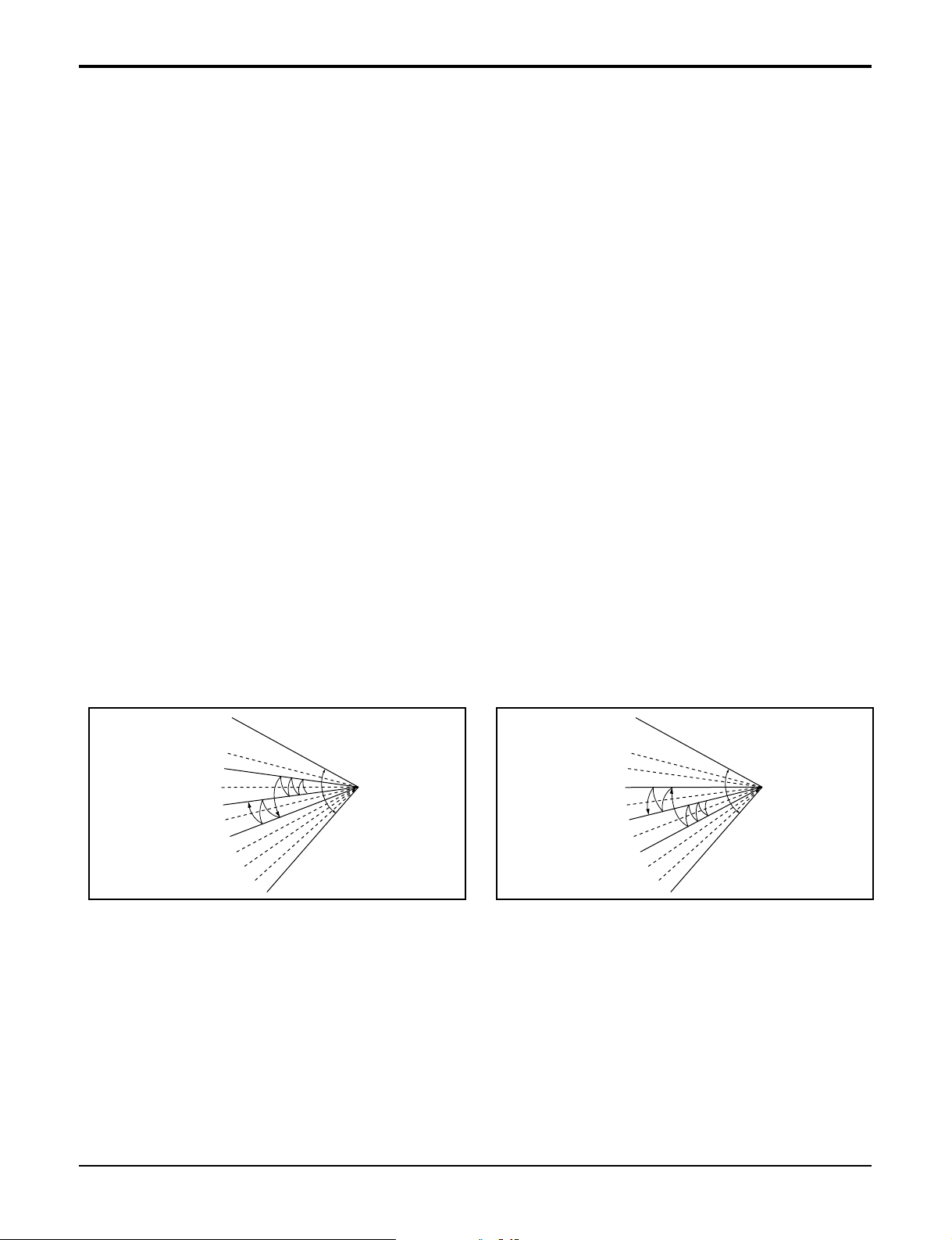
■ Chaos Swing Mode
• By the Chaos Swing key input, the louvers vane automatically operate with the Chaos Swing or they are fixed
to the desired direction.
• While in Chaos Swing mode, the angles of cooling and heating cycle operations are different.
■ Jet Cool Mode Operation (C/O Model)
• If the Jet Cool key is input at any operation mode while in appliance operation, the Jet Cool mode operates.
• In the Jet Cool mode, the indoor fan is operated at super-high speed for 30 min at cooling mode operation.
• In the Jet Cool mode operation, the room temperature is controlled to the setting temperature, 18°C
• When the sleep timer mode is input while in the Jet Cool mode operation, the Jet Cool mode has the priority.
• During the JET COOL function at any moment, the A/C starts to blow the cool air with side louvers closed at
extremely high speed for 30 minutes setting the room temp. automatically to 18°C.
CLOSED
OPEN
< Cooling Mode >
CLOSED
OPEN
< Heating Mode >

22 Room Air Conditioner
Operation Details
■ Jet Cool Mode Operation (H/P Model)
• While in heating mode or Fuzzy operation, the Jet Cool key cannot be input. When it is input while in the other
mode operation (cooling, dehumidification, ventilation), the Jet Cool mode is operated.
• In the Jet Cool mode, the indoor fan is operated at super-high speed for 60 min at cooling mode operation.
• In the Jet Cool mode operation, the room temperature is controlled to the setting temperature, 18°C.
• When the sleep timer mode is input while in the Jet Cool mode operation, the Jet Cool mode has the priority.
• During the JET HEAT function at any moment, the A/C starts to blow the hot air with side louvers closed at
extremely high speed for 60 minutes setting the room temp. automatically to 30°C.
■ Forced Operation
• Operation procedures when the remote control can't be used.
• The operation will be started if the power button is pressed.
• If you want to stop operation, re-press the button.
• While in forced operation, the key input by the remote control has no effect and the buzzer sounds 10 times to
indicate the forced operation.
■ Test operation
•
During the TEST OPERATION, the unit operates in cooling mode at high speed fan, regardless of room temperature and resets in 18±1 minutes.
•
During test operation, if remote controller signal is received, the unit operates as remote controller sets.
If you want to use this operation, open the front panel upward and Press the power button let it be pressed for
about 3 seconds.
•
If you want to stop the operation, re-press the button.
■ Auto restart
•
In case the power comes on again after a power failure, Auto Restarting Operation is the function to operate
procedures automatically to the previous operating conditions.
■ Remote Control Operation Mode
• When the remote control is selected by the slide switch on the main unit, the appliance operates according to
the input by the remote control.
■ Protection of the evaporator pipe from frosting
• If the indoor pipe temp is below 0°C in 7 min. after the compressor operates without any pause while in cool-
ing cycle operation mode, the compressor and the outdoor fan are turned off in order to protect the indoor
evaporator pipe from frosting.
• When the indoor pipe temp is 7°C or higher after 3 min. pause of the compressor, the compressor and the
outdoor fan is turned on according to the condition of the room temperature.
■ Buzzer Sounding Operation
• When the appliance-operation key is input by the remote control, the short "beep-beep-" sounds.
• When the appliance-pause key is input by the remote control, the long "beep—" sounds.
• When a key is input by the remote control while the slide switch on the main unit of the appliance is on the
forced operation position, the error sound "beep-beep-beep-beep-beep-" is made 10 times to indicate that the
remote control signal cannot be received.
Heat pump Model
Cooling Model
Room Temp. ≥24°C21°C ≤Room Temp. < 24°C Room Temp. < 21°C
Operating mode Cooling Cooling Healthy Dehumidification Heating
Indoor FAN Speed
High High High High
Setting Temperature
22°C22°C23°C24°C
 Loading...