


www.lg.com
INSTALLATION MANUAL
AIR CONDITIONER
• Please read this installation manual completely before installing the product.
• Installation work must be performed in accordance with the national wiring
standards by authorized personnel only.
• Please retain this installation manual for future reference after reading it
thoroughly.
P/NO : 3828A20567K

2 Multi Type Air Conditioner
Multi Type Air Conditioner Installation Manual
TABLE OF CONTENTS
Installation Parts Provided ........................................3
Safety Precautions......................................................4
Installation of Indoor, Outdoor Unit...........................7
Wall mounted Type................................................11
Ceiling Concealed Duct Type ................................15
Ceiling Cassette Type ...........................................21
Flaring work and connection of piping...................31
Connecting the Cable between Indoor Unit and
Outdoor Unit ..............................................................44
Checking the Drainage, Forming the Pipings
and Long pipe Setting ..............................................46
Air Purging and Evacuation.....................................48
Test running...............................................................50
Optional Operation - Ceiling Concealed Duct Type
..........51
Optional Operation - Ceiling Cassette Type ...........55
Combination indoor units ........................................58
Installation guide at the seaside..............................59
❏ Level gauge
❏ Screw driver
❏ Electric drill
❏ Hole core drill (ø70mm)
❏ Horizontal meter
❏ Flaring tool set
❏ Specified torque wrenches
1.8kg.m, 4.2kg.m, 5.5kg.m, 6.6kg.m
(different depending on model No.)
❏ Spanner .................Half union
❏ A glass of water
❏ Screw driver
❏ Hexagonal wrench(4mm)
❏ Gas-leak detector
❏ Vacuum pump
❏ Gauge manifold
❏ Owner's manual
❏ Thermometer
❏ Holder Remote Control
Installation Requirements
Required Tools
Installation Parts Provided
Installation Manual 3
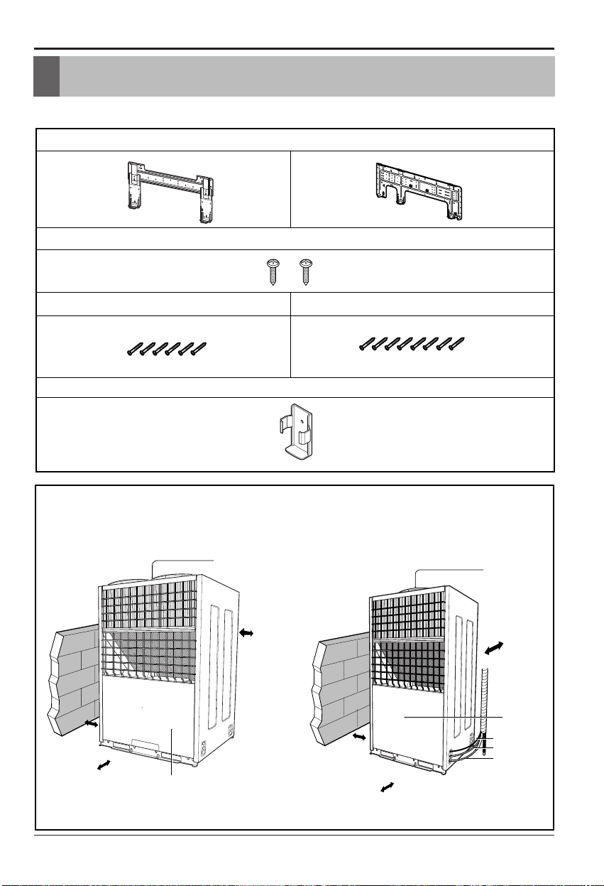
Installation Parts Provided
Outdoor Unit
Wall Mounted Type
more than
25cm
more than
25cm
more than
75cm
more than
25cm
Air Outlet
Control cover
Installation plate
Type "B" screws
Type "A" screw (6 EA) Type "A" screw (8 EA)
Holder Remote Control
more than
25cm
more than
25cm
more than
75cm
more than
25cm
Air Outlet
Connection pipe
Drain hose
Connecting wire
Control cover
4 Multi Type Air Conditioner
Safety Precautions
To prevent injury to the user or other people and property damage, the following instructions
must be followed.
■ Incorrect operation due to ignoring instruction will cause harm or damage. The seriousness
is classified by the following indications.
■ Meanings of symbols used in this manual are as shown below.
This symbol indicates the possibility of death or serious injury.
This symbol indicates the possibility of injury or damage.
Be sure not to do.
Be sure to follow the instruction.
Safety Precautions
WARNING
■ Installation
Install the panel and the cover of
control box securely.
• There is risk of fire or
electric shock.
Always install a dedicated
circuit and breaker.
• Improper wiring or
installation may cause fire or
electric shock
Use the correctly rated breaker
or fuse.
• There is risk of fire or
electric shock.
Do not use a defective or
underrated circuit breaker. Use
this appliance on a dedicated
circuit.
• There is risk of fire or
electric shock.
For electrical work, contact the
dealer, seller, a qualified
electrician, or an Authorized
Service Center.
•
Do not disassemble or repair
the product. There is risk of
fire or electric shock.
Always ground the product.
• There is risk of fire or
electric shock.
WARNING
CAUTION

Installation Manual 5
Safety Precautions
Do not modify or extend the power cable.
• There is risk of fire or electric shock.
Be cautious when unpacking and installing the
product.
•
Sharp edges could cause injury. Be especially
careful of the case edges and the fins on the
condenser and evaporator.
For installation, always contact the dealer or an
Authorized Service Center.
• There is risk of fire, electric shock, explosion,
or injury.
Do not install the product on a defective
installation stand.
• It may cause injury, accident,
or damage to the product.
Be sure the installation area does not
deteriorate with age.
•
If the base collapses, the air conditioner could fall with
it, causing property damage, product failure, and
personal injury.
Do not let the air conditioner run for a long time when
the humidity is very high and a door or a window is
left open.
• Moisture may condense and wet or damage
furniture.
Do not store or use flammable gas or combustibles
near the product.
• There is risk of fire or failure of product.
Use a vacuum pump or Inert (nitrogen) gas when
doing leakage test or air purge. Do not compress air
or Oxygen and Do not use Flammable gases.
Otherwise, it may cause fire or explosion.
• There is the risk of death, injury, fire or
explosion.
n Operation
6 Multi Type Air Conditioner
Safety Precautions
Always check for gas (refrigerant) leakage after
installation or repair of product.
• Low refrigerant levels may cause failure of
product.
Install the drain hose to ensure that water is
drained away properly.
• A bad connection may cause water leakage.
Keep level even when installing the product.
• To avoid vibration or water leakage.
Do not install the product where the noise or hot air
from the outdoor unit could damage the
neighborhoods.
• It may cause a problem for your neighbors.
Don't let people to lift and transport the
product. (Use fork lift)
• Avoid personal injury.
Do not install the product where it will be
exposed to sea wind (salt spray) directly.
• It may cause corrosion on the product.
Corrosion, particularly on the condenser and
evaporator fins, could cause product
malfunction or inefficient operation.
CAUTION
■ Installation
Installation Manual 7
Installation of Indoor, Outdoor Unit
Installation of Indoor, Outdoor Unit
Read completely, then follow step by step.
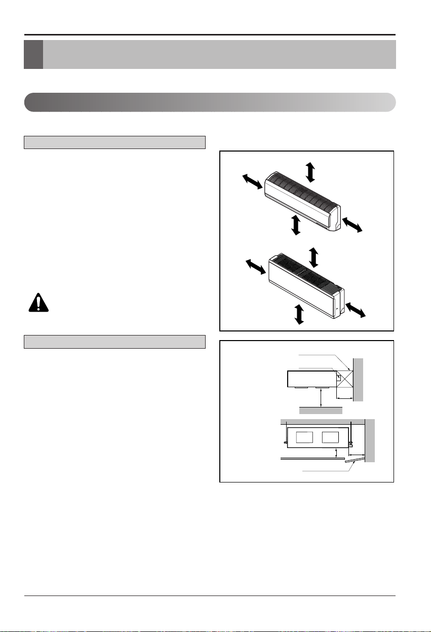
1. Indoor unit
• Do not have any heat or steam near the unit.
• Select a place where there are no obstacles in
front of the unit.
• Make sure that condensation drainage can be
conveniently routed away.
• Do not install near a doorway.
• Ensure the spaces indicated by arrows from
the wall, ceiling, fence or other obstacles.
• Use a stud finder to locate studs to prevent
unnecessary damage to the wall.
Install the air conditioner in the location that
satisfies the following conditions.
• The place shall easily bear a load exceeding
four times the indoor unit’s weight.
• The place shall be able to inspect the unit as
the figure.
• The place where the unit shall beleveled.
• The place shall allow easy water
drainage.(Suitable dimension “H” is necessary
to get a slope to drain as figure.)
• The place shall easily connect with the
outdoor unit.
• The place where the unit is not affected by an
electrical noise.
• The place where air circulation in the room will
be good .
• There should not be any heat source or steam
near the unit
Select the best location
H
600
600
Top view
(unit: mm)
Front view
Front
Inspection Hole
(600X600)
Inspection Hole
(600X600)
Control box
1000
More than 20cm
More than
10cm
More than 2.3m
More than
10cm
More than 20cm
More than
10cm
More than 2.3m
More than
10cm
CAUTION: Install the indoor unit
on the wall where the height from
the floors more than 2.3 meters.
Wall mounted Type
Ceiling Concealed Duct Type
8 Multi Type Air Conditioner
Installation of Indoor, Outdoor Unit
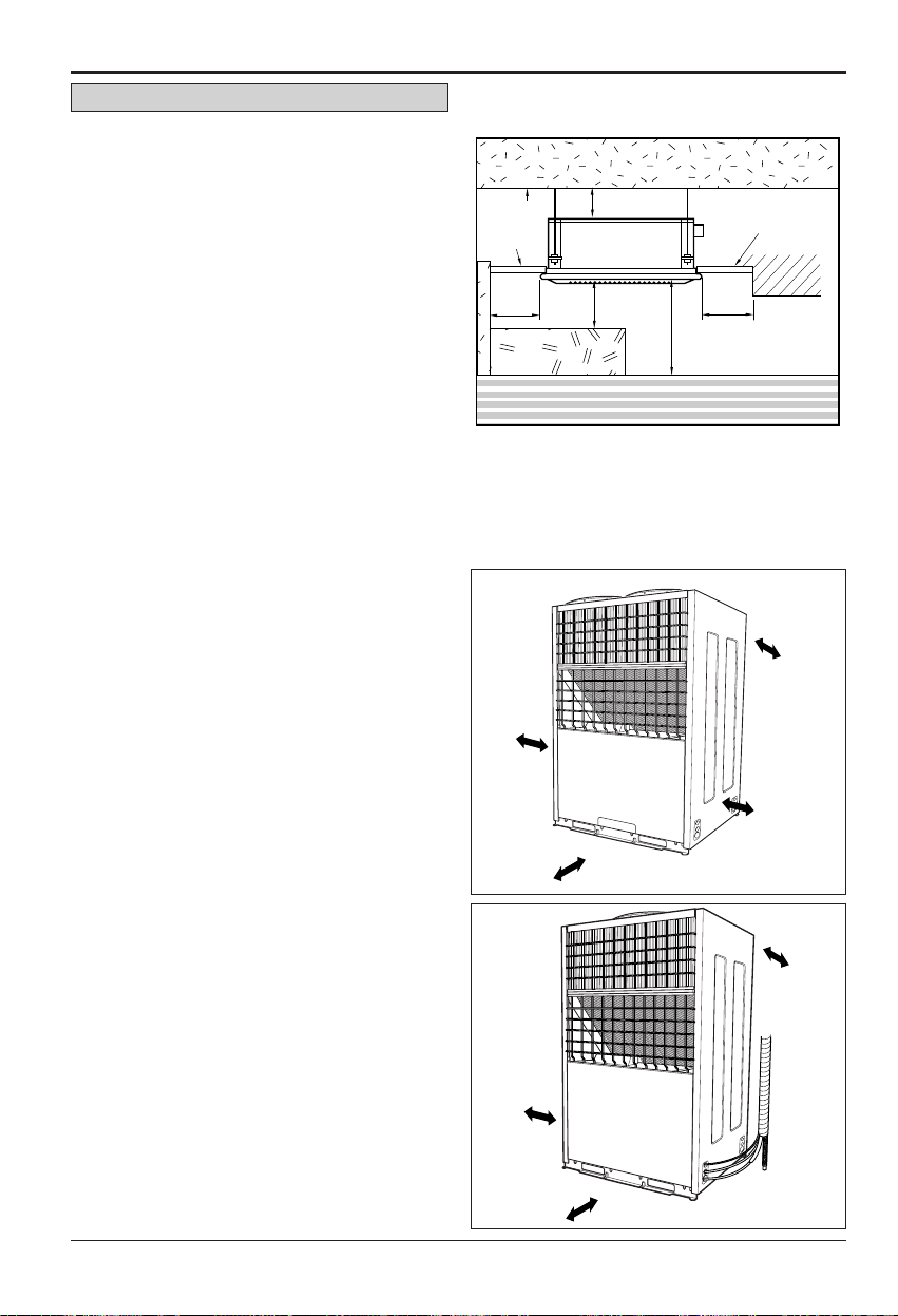
2. Outdoor unit
1. If an awning is built over the unit to prevent
direct sunlight or rain exposure, make sure
that heat radiation from the condenser is not
restricted.
2. Ensure that the spaces indicated by arrows
around front, back and side of the unit.
3. Do not place animals and plants in the path
of the warm air.
4. Take the air conditioner weight into account
and select a place where noise and vibration
are minimum.
5. Select a place so that the warm air and noise
from the air conditioner do not disturb
neighbors.
Rooftop Installations:
If the outdoor unit is installed on a roof
structure, be sure to level the unit. Ensure the
roof structure and anchoring method are
adequate for the unit location. Consult local
codes regarding rooftop mounting.
• There should not be any heat source or steam
near the unit.
• There should not be any obstacles to prevent
the air circulation.
• A place where air circulation in the room will
be good.
• A place where drainage can be easily
obtained.
• A place where noise prevention is taken into
consideration.
• Do not install the unit near the door way.
• Ensure the spaces indicated by arrows from
the wall, ceiling, or other obstacles.
• The indoor unit must keep the maintenance
space.
Ceiling Cassette Type
Ceiling
Ceiling Board
500 or
more
more than
25 cm
more than
75 cm
more than
25cm
20 or more
1500
or more
Floor
Ceiling Board
500 or
more
H
Unit:mm
more than
25 cm
more than
25 cm
more than
25cm
more than
75cm
Installation of Indoor, Outdoor Unit
Installation Manual 9
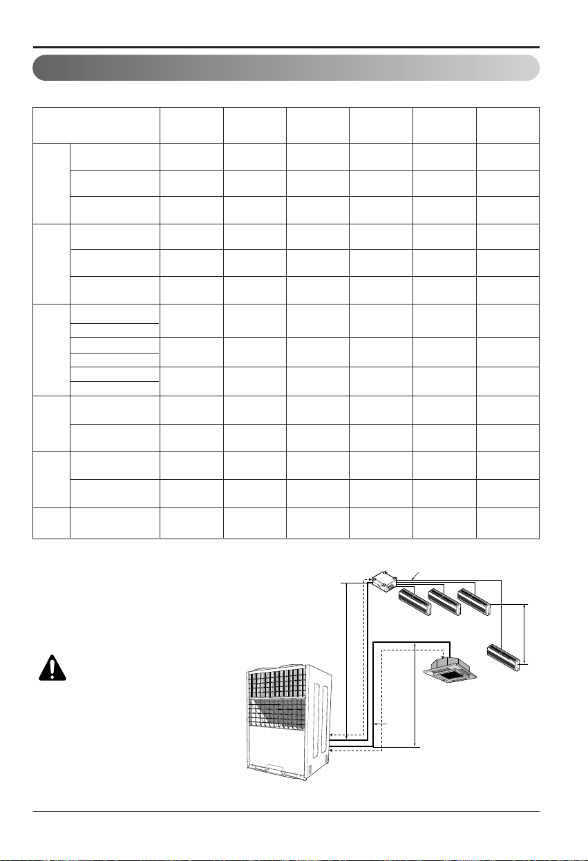
Piping length and elevation table.
Piping length and elevation
60 A = 30 30 15 h1=30 10
50 B = 50 - - h2=30 10
30 B = 30 - - h2=30 10
110 A = 50 60 15 h1=45 10
50 B = 50 - - h2=45 10
45 A = 30 15 15 h1=30 10
50 B = 50 - - h2=30 10
60 A = 30 30 15 h1=30 10
50 A=50 - - h1=30 10
110 A=50 60 15 h1=45 10
50 B=50 - - h2=45 10
110 B=50 60 15 h2=45 10
Total Length
Max Main Pipe
Length (A/B)
Total Branch
Pipe Length
Max Branch
Pipe Length
Max Elevation
(h1/h2)
Indoor - Indoor
Elevation (h3)
h3
h1
h2
A
B
Branch Pipe
Main Pipe
Distributor
CAUTION: Capacity is based
on standard length and
maximum allowance length
is on the basis of reliability.
When outdoor unit is at
higher elevation than the
indoor units, after 24m of
vertical height, 1 oil trap is
required.
Model
With Distributor
With Distributor
L5UC7
28FA2
L5UC7
28FA3
L6UH7
28FA2
L8UC1
508FA1
L8UC10
08FA2
L8UH10
08FA2
L8UC10
08FA3
None Distributor
A-Circuit
None Distributor
A-Circuit
With Distributor
With Distributor
With Distributor
None Distributor
None Distributor
None Distributor
B-Circuit
None Distributor
B-Circuit
50 A = 50 - - h1=45 10
60 B = 30 30 15 h2=30 10
With Distributor
A-Circuit
With Distributor
B-Circuit
None Distributor
A-Circuit
10 Multi Type Air Conditioner
Installation of Indoor, Outdoor Unit
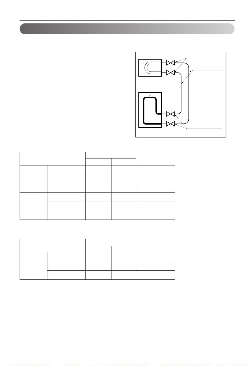
Flared connection (Union)
Flared connection
(Service valve, Ball valve)
Use a seemliness tube
Factory charged
Indoor
Outdoor
Perform the work according to the Service Manual or Installation Guide.
• Use two spanners when connecting the
refrigerant pipe to the unit.
• Make a bend with a radius as large as
possible.
• Perform air purge with R22 or vacuum drying.
• When piping work is finished, check all joints.
■
Add refrigerant if piping over 7.5m as shown
below, non distributor type.
■ Add refrigerant if piping over 5m (main pipe),
7.5m (branch pipe) as shown below, distributor
type.
24 kBtu/h 15.88 6.35 30g/m
48/60 kBtu/h 19.05 9.52 50g/m
90 kBtu/h 25.4 12.7 120g/m
12/18 kBtu/h 12.7 6.35 20g/m
24/30/36 kBtu/h
15.88 6.35 30g/m
48 kBtu/h 19.05 9.52 50g/m
Main Pipe
Branch Pipe
Additional
Refrigerant
Pipe
Gas Liquid
Refrigerant piping
Table. Distributor type
12/18 kBtu/h 12.7 6.35 20g/m
24/30/36 kBtu/h
15.88 6.35 30g/m
48 kBtu/h 19.05 9.52 50g/m
Branch Pipe
Additional
Refrigerant
Pipe
Gas Liquid
Table. Non Distributor type
Installation Manual 11
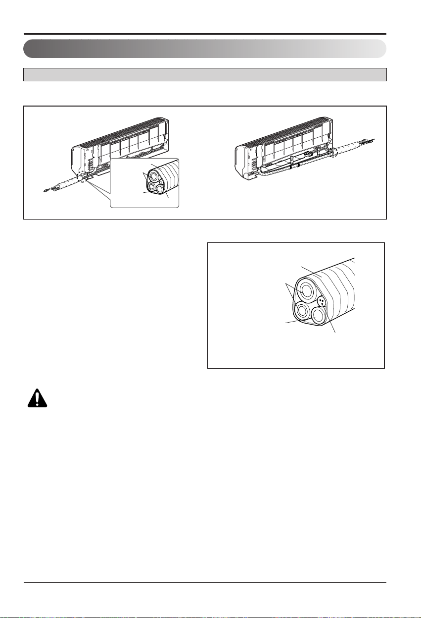
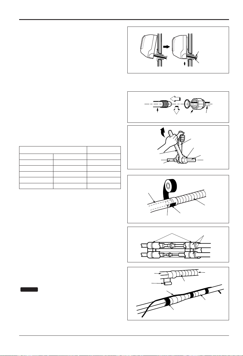
2. Tape the tubing, drain hose and the
connecting cable. Be sure that the drain hose
is located at the lowest side of the bundle.
Locating at the upper side can cause drain
pan to overflow inside the unit.
1. Route the indoor tubing and the drain hose in the direction of rear left or right
Connecting
pipe
Connecting cable
Tape
Drain hose
Connecting
pipe
Connecting cable
Tape
Drain hose
CAUTION: If the drain hose is routed inside the room, insulate the hose with
an insulation material* so that dripping from "sweating"(condensation) will
not damage furniture or floors.
*Foamed polyethylene or equivalent is recommended.
Installation of Indoor, Outdoor Unit
Indoor unit installation
Wall Mounted Type
12 Multi Type Air Conditioner
Installation of Indoor, Outdoor Unit
■ Indoor unit installation on
installation plate
1. Hook the indoor unit onto the upper portion of
the installation plate.(Engage the two hooks
of the rear top of the indoor unit with the
upper edge of the installation plate.) Ensure
that the hooks are properly seated on the
installation plate by moving it left and right.
Press the lower left and right sides of the unit
against the installation plate until the hooks
engage into their slots(clicking sound).
Connecting the pipings to the in
door unit and drain hose to drain
pipe
1. Align the center of the pipings and sufficiently
tighten the flare nut by hand.
2. Tighten the flare nut with a wrench.
3. When extending the drain hose at the indoor
unit, install the drain pipe.
Wrap the insulation material
around the connecting portion.
1. Overlap the connection pipe insulation
material and the indoor unit pipe insulation
material. Bind them together with vinyl tape
so that there is no gap.
2. Wrap the area which accommodates the rear
piping housing section with vinyl tape.
: Recommended Insulation material
Meterial: FOAM PE
Thickness: 10mm
Density: less than 0.032 ±0.005(g/cm
3
)
Thermal conductivity: less than 0.03
(kcal/m·h°C)
NOTICE
Drain hose
Connecting
cable
mm inch kgf.cm
Ø6.35 1/4 180~250
Ø9.52 3.8 340~420
Ø12.7 1/2 550~560
Ø15.88 5/8 630~820
Ø19.05 3/4 990~1 210
Outside diameter Torque
Indoor unit tubing Flare nut Pipings
Spanner (fixed)
Flare nut
Torque wrench
Indoor unit tubing
Drain pipe
Indoor unit drain hose
Vinyl tape(narrow)
Adhesive
Connection pipe
Connection
pipe
Vinyl tape
(wide)
Plastic bands
Connecting cable
Vinyl tape(narrow)
Insulation material
Wrap with vinyl tape
Indoor
unit pipe
Pipe
Installation Manual 13
3. Bundle the piping and drain hose together by
wrapping them with vinyl tape over the range
within which they fit into the rear piping
housing section.
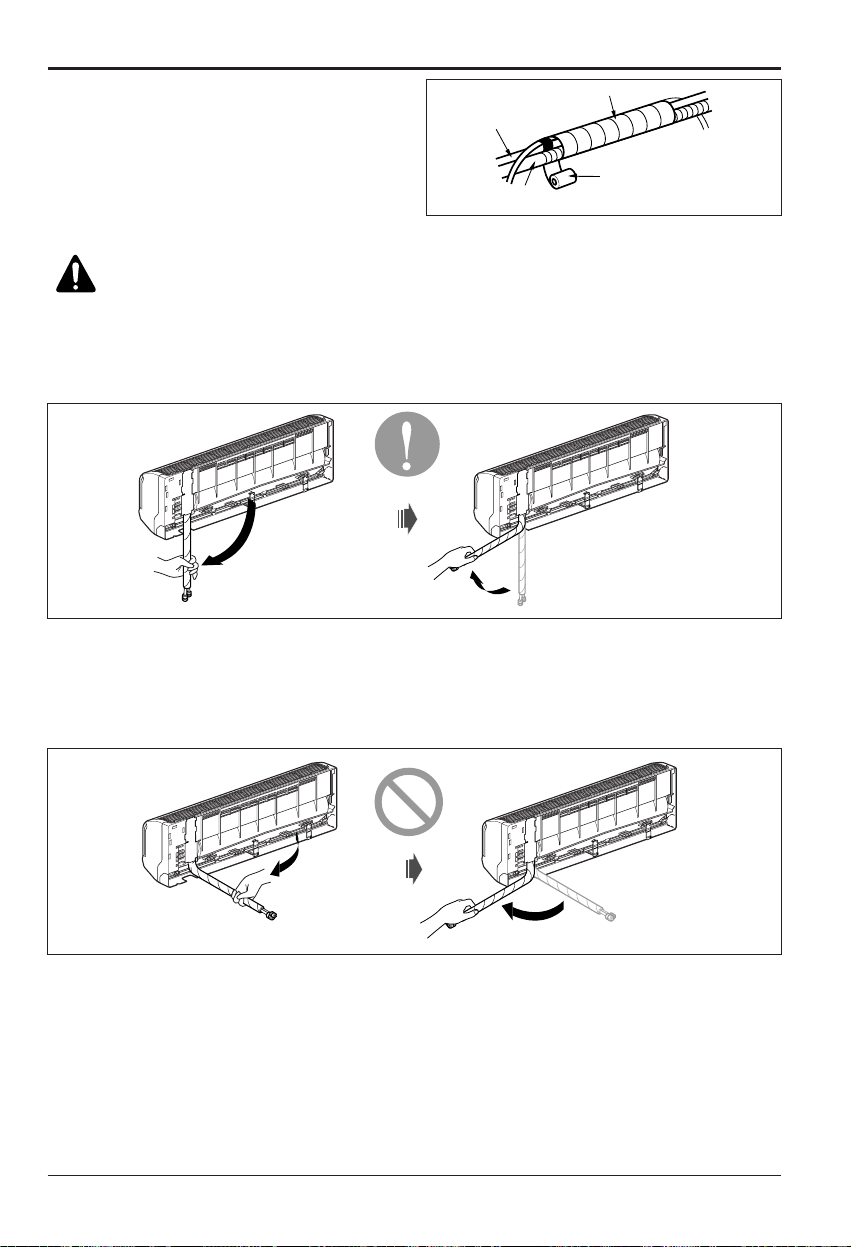
Good case
• Press on the upper side of clamp and unfold
the tubing to downward slowly.
Bad case
• Following bending type from left to right could
cause problem of pipe damage.
Wrap with vinyl tape
Drain hose
Pipe
Vinyl tape(wide)
CAUTION: Installation Information (For right piping)
For right piping, follow the instruction below.
Installation of Indoor, Outdoor Unit
14 Multi Type Air Conditioner
Installation of Indoor, Outdoor Unit
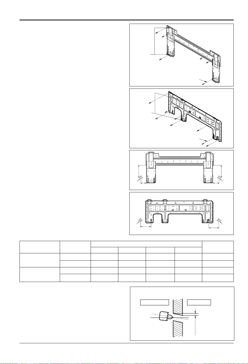
The wall you select should be strong and solid
enough to prevent vibration
1. Mount the installation plate on the wall with
type "A" screws. If mounting the unit on a
concrete wall, use anchor bolts.
• Mount the installation plate horizontally by
aligning the centerline using a level.
2. Measure the wall and mark the centerline. It
is also important to use caution concerning
the location of the installation plate-routing
of the wiring to power outlets is through the
walls typically. Drilling the hole through the
wall for piping connections must be done
safely.
■ How to fix installation plate
• Drill the piping hole with a ø70mm hole core
drill. Drill the piping hole at either the right or
the left with the hole slightly slanted to the
outdoor side.
■ Drill a hole in the wall
5-7mm
(3/16"~5/16")
Indoor
WALL
Outdoor
Standard
<Type 1>
<Type 1>
Installation plate
Left rear piping Right rear piping
Ø70mm
133mm
Ø70mm
100mm
<Type 2>
Chassis
Hook
Installation Plate
Type “A”
<Type 2>
Wall mounted
12 55 105 65 105 1
18,24 100 122 240 122 2
ART COOL Mirror
12 70 110 90 110 1
18,24 100 122 240 122 2
Indoor Type
Capacity
(kBtu/h)
Distance (mm)
Type
ABCD
Installation Plate
Chassis
Hook
Type “A”
D
C
Ø70mm
Left rear piping Right rear piping
Installation plate
B
A
Ø70mm
Installation of Indoor, Outdoor Unit
Installation Manual 15
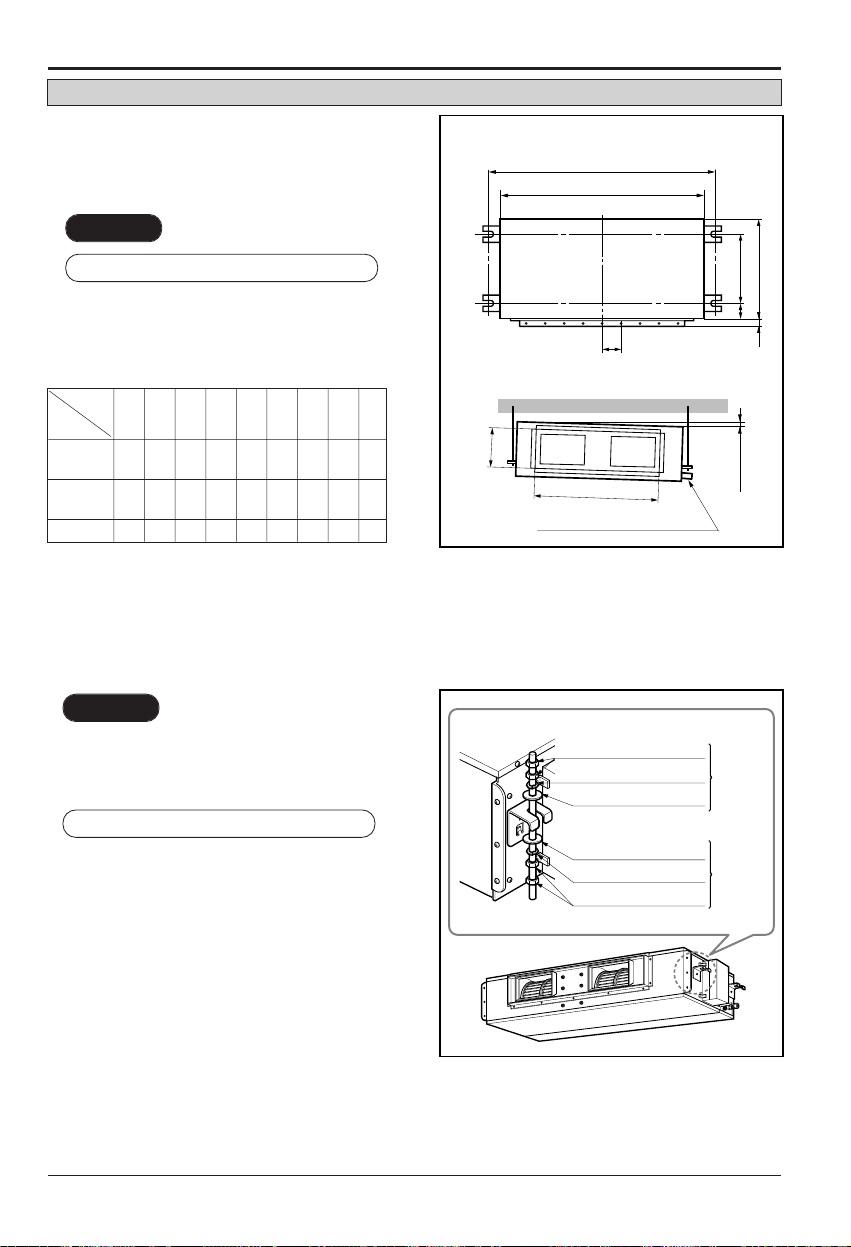
Ceiling Concealed Duct Type
■ Installation of Unit
Install the unit above the ceiling correctly.
• Apply a joint-canvas between the unit and
duct to absorb unnecessary vibration.
• Apply a filter Accessory at air return hole.
• Install the unit leaning to a drainage hole
side as a figure for easy water drainage.
• A place where the unit will be leveled and
that can support the weight of the unit.
• A place where the unit can withstand its
vibration.
• A place where service can be easily
performed.
CASE 1
POSITION OF SUSPENSION BOLT
CASE 2
POSITION OF CONSOLE BOLT
(Unit:mm)
Drainage hole
A
B
C
1-3 mm
D
(G)
H
I
EF
M10 SP. washer
M10 washer
M10 Nut
X 8
X 4
(Local
supply)
X 4
M10 Nut
M10 SP. washer
M10 washer
X 4
X 4
(Local
supply)
X 8
18 kBtu/h
932 880 355 45.5 450 30 87 750 163
24 kBtu/h
30 kBtu/h
1 232 1 180 355 45.5 450 30 87 830 186
36 kBtu/h
48 kBtu/h 1 292 1 230 477 56 590 30 120 1 006 294
Dimension
Capacity
A B C D E F (G) H I
16 Multi Type Air Conditioner
Installation of Indoor, Outdoor Unit
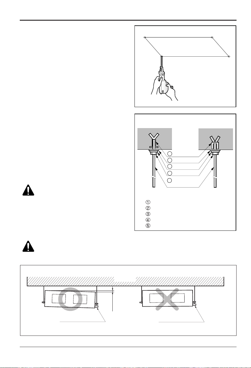
• Select and mark the position for fixing bolts.
• Drill the hole for set anchor on the face of
ceiling.
• Insert the set anchor and washer onto the
suspension bolts for locking the suspension
bolts on the ceiling.
• Mount the suspension bolts to the set
anchor firmly.
• Secure the installation plates onto the
suspension bolts (adjust level roughly)
using nuts, washers and spring washers.
1 Set anchor
Old building New building
2 Plate washer
3 Spring washer
4 Nut
5 Suspension
bolts
• Local supply
Set anchor
Plate washer - M10
Spring washer - M10
Nut - W3/8 or M10
Suspension bolt - W3/8 or M10
CAUTION:Tighten the nut and
bolt to prevent unit falling
CAUTION:
1. Install declination of the indoor unit is very important for the drain of the duct type air
conditioner.
2. Minimum thickness of the insulation for the connecting pipe shall be 10mm.
Front of view
• The unit must be horizontal or declined to the drain hose connected when finished installation.
CORRECT
INCORRECT
Drainage hole
Ceiling
1~3mm
Drainage hole
Installation of Indoor, Outdoor Unit
Installation Manual 17
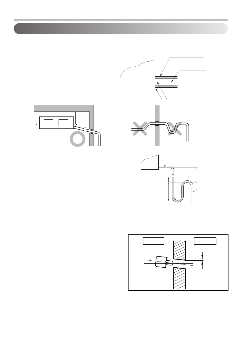
• Always lay the drain with downward
inclination (1/50 to 1/100).
Prevent any upward flow or reverse flow
in any part.
• 5mm or thicker formed thermal insulator
shall always be provided for the drain
pipe.
Lay the drain hose with a downward inclination so water will drain out.
• Install the P-Trap (or U-Trap) to prevent a
water leakage caused by the blocking of
intake air filter.
Applied U-Trap Dimension
CORRECT
INCORRECT
• Upward routing not
allowed
Caution for gradient of unit and drain piping
• Drill the piping hole with 70mm dia, hole
core drill.
• Piping hole should be slightly slant to the
outdoor side.
Unit
Make sure to be closed.
A ≥ 70mm
B ≥ 2C
C ≥ 2 x SP
SP = External Pressure
(mmAq)
Ex) External Pressure
= 10mmAq
A ≥ 70mm
B ≥ 40mm
C ≥ 20mm
Thermal insulator
(Local supply)
Drainage pipe
(Local supply)
Drainage hole
C
A
B
U-Trap
Indoor Outdoor
WALL
5~7mm
18 Multi Type Air Conditioner
Installation of Indoor, Outdoor Unit
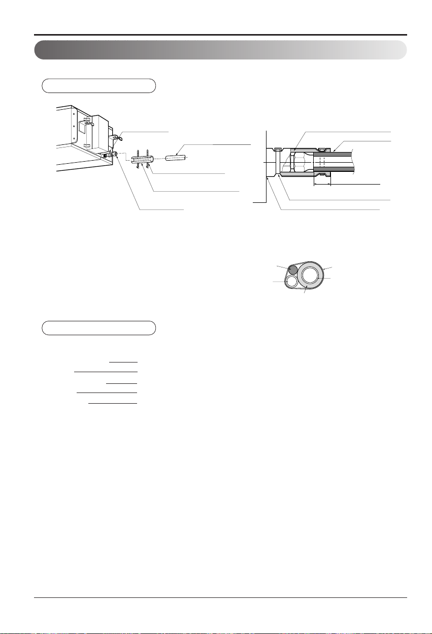
Insulate the joint and tubes completely.
All thermal insulation must comply with local requirement.
REFRIGERANT PIPE
• Insulate and tape the gas piping.
■ After all workings are finished, check the working and operation.
• Air distribution Is the air circulation good?
• Drain Is the drainage smooth and no sweating?
• Gas leakage Is the piping connection correct?
• Wiring Is the wiring connection correct?
• Lock-bolt Is the lock-bolt of compressor loosened?
THERMAL INSULATION
TEST AND CHECK
Make sure that there is no clearance here.
Overlap with thermal
insulator for piping.
Thermal insulator for refrigerant pipe
(Local supply)
Thermal insulator for
piping(Local supply)
Hose clip for thermal insulator(Local supply)
Union for liquid pipe
Refrigerant pipe and thermal
insulator(Local supply)
Union for gas pipe
Thermal insulator for refrigerant pipe
(Local supply)
Hose clip for thermal insulator
(Local supply)
Power cable
Thermal insulator
Gas pipe
Liquid pipe
Tape
Insulation, others
 Loading...