

LG L3UC482FA0, L4UC602FA0, L4UH602FA0 Installation Manual
ENGLISH ESPAÑOL
LG
Multi Type Air Conditioner
INSTALLATION MANUAL
LG
website http://www.lgservice.com
e-mail http://www.lgeservice.com/techsup.html
IMPORTANT
• Please read this installation manual completely before
installing the product.
• When the power cord is damaged, replacement work shall
be performed by authorized personnel only.
• Installation work must be performed in accordance with
the national wiring standards by authorized personnel
only.

2 Multi Type Air Conditioner
Multi Type Air Conditioner Installation Manual
TABLE OF CONTENTS
Installation Parts Provided .........................................3
Safety Precautions .....................................................4
Installation of Indoor, outdoor Unit ..........................7
Flaring Work and Piping Connection......................10
Connecting the cable between Indoor Unit and
Outdoor Unit .............................................................15
Checking the Drainage and Forming the Pipings
....................................................................................17
Test of the leakage....................................................19
Test Running..............................................................21
❏ Level gauge
❏ Screw driver
❏ Electric drill
❏ Hole core drill (ø50mm)
❏ Horizontal meter
❏ Flaring Tools set
❏ Specified to torque wrenches 1.8kg.m,
4.2kg.m, 5.5kg.m, 6.6kg.m (different
depending on model No.)
❏ Spanner....................Half union
❏ A glass of water
❏ Screw driver
❏ Hexagonal Wrench (4mm)
❏ Gas-leak Detector
❏ Vacuum pump
❏ Gauge manifold
Installation Requirements
Required T ools
Installation Parts Provided
Installation Manual 3
ENGLISH
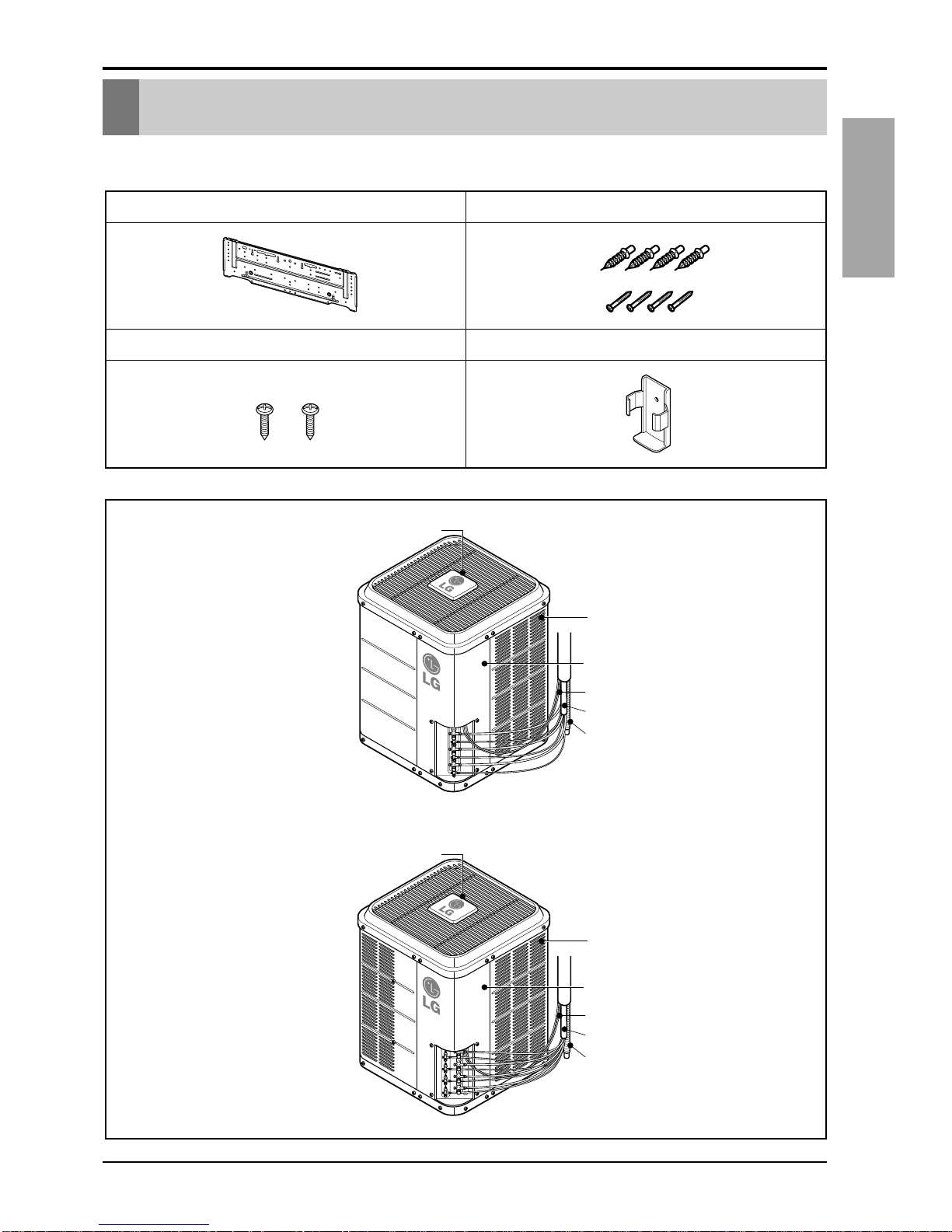
Installation Parts Provided
Type "A" screws and plastic anchors
Type "B" screws
Holder Remote Control
Installation plate
Standard Type
(Side)
(Rear)
Air intake
vents
Air outlet vents
Piping
Drain hose
Control cover
Connecting wire
(Side)
(Rear)
Air intake
vents
Air outlet vents
Piping
Drain hose
Control cover
Connecting wire
48K Btu/h
60K Btu/h
4 Multi Type Air Conditioner
Safety Precautions
Safety Precautions
To prevent injury to the user or other people and property damage, the following instructions
must be followed.
■
Incorrect operation due to ignoring instruction will cause harm or damage. The
seriousness is classified by the following indications.
■ Meanings of symbols used in this manual are as shown below.
WARNING
CAUTION
This symbol indicates the possibility of death or serious injury.
This symbol indicates the possibility of injury or damage.
WARNING
Be sure not to do.
Be sure to follow the instruction.
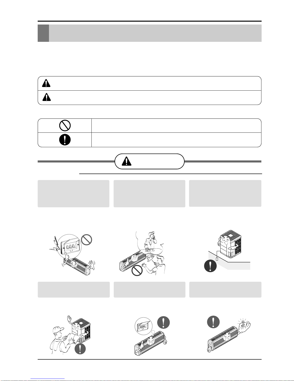
■ Installation
Install the panel and the cover of
control box securely.
• There is risk of fire or
electric shock.
Always install a dedicated
circuit and breaker.
• Improper wiring or
installation may cause fire or
electric shock
Use the correctly rated breaker
or fuse.
• There is risk of fire or
electric shock.
Do not use a defective or
underrated circuit breaker. Use
this appliance on a dedicated
circuit.
• There is risk of fire or
electric shock.
For electrical work, contact the
dealer, seller, a qualified
electrician, or an Authorized
Service Center.
•
Do not disassemble or repair
the product.There is risk of
fire or electric shock.
Always ground the product.
• There is risk of fire or
electric shock.
ENGLISH
Installation Manual 5
Safety Precautions
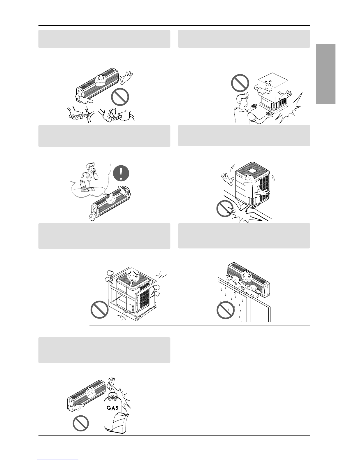
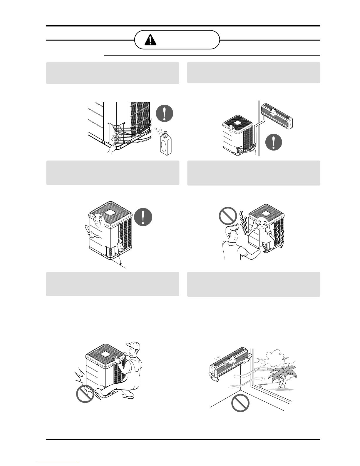
Do not modify or extend the power cable.
• There is risk of fire or electric shock.
Be cautious when unpacking and installing the
product.
•
Sharp edges could cause injury.Be especially
careful of the case edges and the fins on the
condenser and evaporator.
For installation, always contact the dealer or an
Authorized Service Center.
• There is risk of fire, electric shock, explosion,
or injury.
Do not install the product on a defective
installation stand.
• It may cause injury, accident, or damage to
the product.
Be sure the installation area does not
deteriorate with age.
•
If the base collapses, the air conditioner could fall with
it, causing property damage, product failure, and
personal injury.
Do not let the air conditioner run for a long time when
the humidity is very high and a door or a window is
left open.
• Moisture may condense and wet or damage
furniture.
Do not store or use flammable gas or combustibles
near the product.
• There is risk of fire or failure of product.
■ Operation
Gasolin
6 Multi Type Air Conditioner
Safety Precautions
Always check for gas (refrigerant) leakage after
installation or repair of product.
• Low refrigerant levels may cause failure of
product.
Install the drain hose to ensure that water is
drained away properly.
• A bad connection may cause water leakage.
Keep level even when installing the product.
• To avoid vibration or water leakage.
Do not install the product where the noise or hot air
from the outdoor unit could damage the
neighborhoods.
• It may cause a problem for your neighbors.
Use two or more people to lift and transport the
product.
• Avoid personal injury.
Do not install the product where it will be
exposed to sea wind (salt spray) directly.
• It may cause corrosion on the product.
Corrosion, particularly on the condenser and
evaporator fins, could cause product
malfunction or inefficient operation.
CAUTION
90°
■ Installation
Installation Manual 7
ENGLISH
Installation of Indoor, Outdoor Unit
Installation of Indoor, Outdoor Unit
Read completely, then follow step by step.
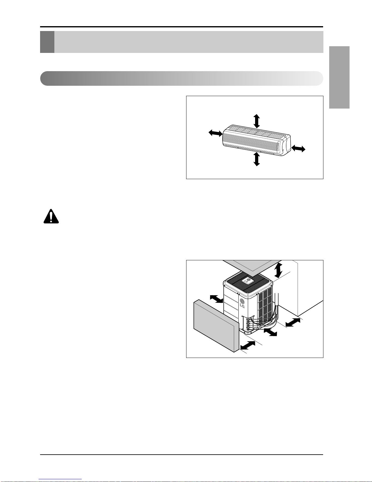
Indoor unit
1. Do not have any heat or steam near the unit.
2. Select a place where there are no obstacles
in front of the unit.
3. Make sure that condensation drainage can be
conveniently routed away.
4. Do not install near a doorway.
5. Ensure the spaces indicated by arrows from
the wall, ceiling, fence or other obstacles.
6. Use a stud finder to locate studs to prevent
unnecessary damage to the wall.
Outdoor unit
1. If an awning is built over the unit to prevent
direct sunlight or rain exposure, make sure
that heat radiation from the condenser is not
restricted.
2. Ensure that the spaces indicated by arrows
around front, back and side of the unit.
3. Do not place animals and plants in the path
of the warm air.
4.Take the air conditioner weight into account
and select a place where noise and vibration
are minimum.
5. Select a place so that the warm air and noise
from the air conditioner do not disturb
neighbors.
Rooftop Installations:
If the outdoor unit is installed on a roof
structure, be sure to level the unit.Ensure the
roof structure and anchoring method are
adequate for the unit location. Consult local
codes regarding rooftop mounting.
Select the best location
More than 5cm
More than
5cm
More than 2.3m
More than
5cm
More than 120cm
More than
90cm
More than 90cm
More than 90cm
More than
90cm
Fence or
obstacles
Fence or
obstacles
Fence or
obstacles
CAUTION: Install the indoor unit
on the wall where the height from
the floors more than 2.3 meters.
8 Multi Type Air Conditioner
Installation of Indoor, Outdoor Unit
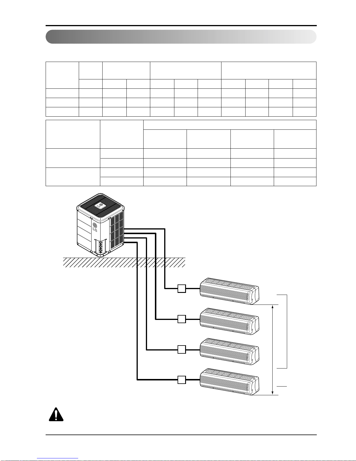
Multi Piping Type (m)
Piping length and elevation
L3UC482FA0 7.5 20 20 30 - 30 50 - 30 80
L4UC602FA0 7.5 20 20 - 30 30 - 50 30 80
L4UH602FA0 7.5 20 15 - 30 20 - 50 20 70
Model
A/B/C/D A/B/C D A/B A/B/C D A/B A/B/C D Total
Standard
Length
Elavation
Max. Piping length each
Indoor unit
Max.Total Piping length
48k
12k 1/2" 1/4" 7.5 30
24k 5/8" 3/8" 7.5 30
60k
12k 1/2" 1/4" 7.5 20
24k 5/8" 3/8" 7.5 70
Outdoor Capacity
(Btu/h)
Indoor Capacity
(Btu/h)
Pipe Size
Gas Liquid
Standard Length
Additional Refrigerant
(m) (g/m)
7.5
Circuit 1
• It does not matter which unit is higher.
Circuit 2
A
B
C
D
CAUTION: Capacity is based on standard length and maximum allowance
length is on the basis of reliability.
Oil trap should be installed every 5~7 meters.
Installation Manual 9
ENGLISH
Installation of Indoor, Outdoor Unit
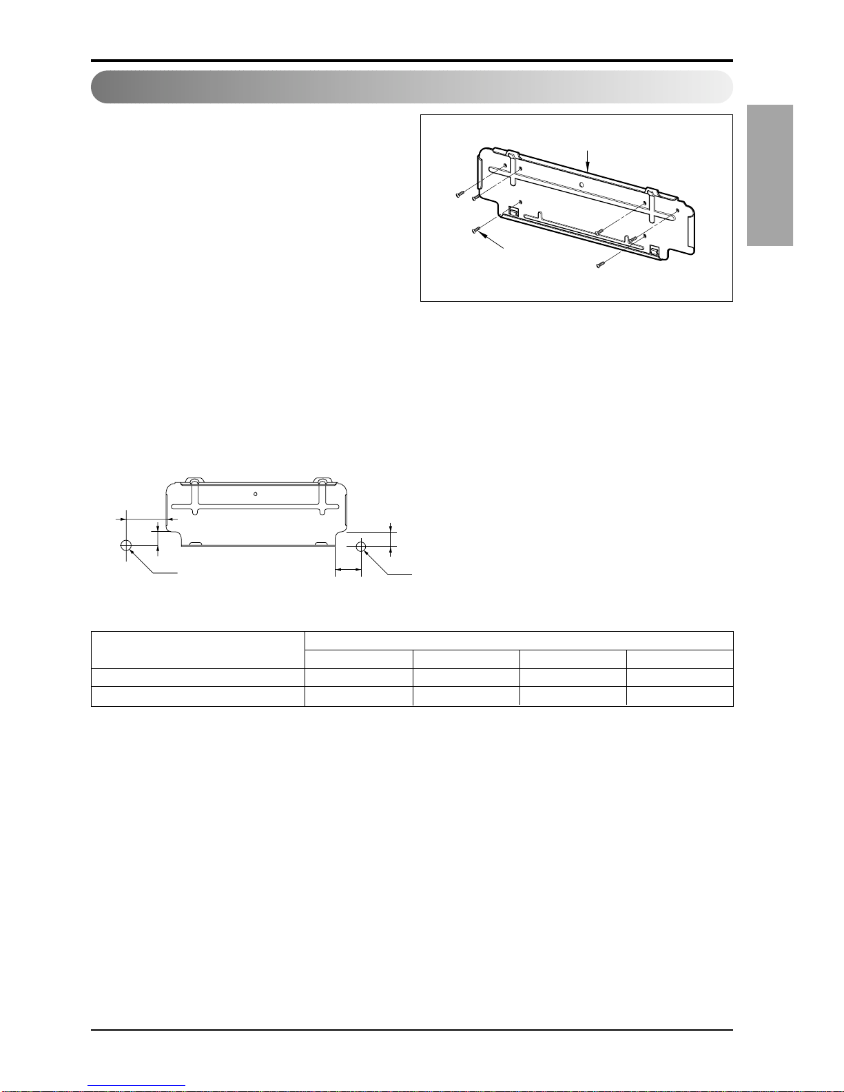
The wall you select should be strong and solid
enough to prevent vibration
1. Mount the installation plate on the wall with
type "A" screws.If mounting the unit on a
concrete wall, use anchor bolts.
• Mount the installation plate horizontally by
aligning the centerline using a level.
2. Measure the wall and mark the centerline.It
is also important to use caution concer ning
the location of the installation plate-routing
of the wiring to power outlets is through the
walls typically. Drilling the hole through the
wall for piping connections must be done
safely.
How to fix installation plate
Installation Plate
Type "A" screw
Installation plate
Ø70mm
Left rear piping Right rear piping
C
D
B
A
Ø70mm
(SR, ST)
SR(9k~12k) 0 40 20 40
ST(18k~24k) 105 0 210 0
CHASSIS (Grade)
Distance (mm)
ABCD
10 Multi Type Air Conditioner
Flaring Work and Piping Connection
Flaring Work and Piping Connection
Flaring work
Main cause for gas leakage is due to defect in flaring work. Carry out correct flaring work in the
following procedure.
Cut the pipes and the cable.
1. Use the piping kit accessory or the pipes
purchased locally.
2. Measure the distance between the indoor and
the outdoor unit.
3. Cut the pipes a little longer than measured
distance.
4.
Cut the cable 1.5m longer than the pipe length.
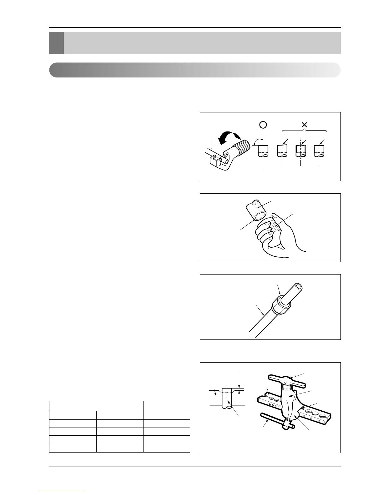
Burrs removal
1. Completely remove all burrs from the cut cross
section of pipe/tube.
2. Put the end of the copper tube/pipe in a
downward direction as you remove burrs in
order to avoid dropping burrs into the tubing.
Putting nut on
• Remove flare nuts attached to indoor and
outdoor unit, then put them on pipe/tube having
completed burr removal.
(not possible to put them on after flaring work)
Flaring work
• Carry out flaring work using flaring tool as shown
below.
• Firmly hold copper pipe in a die in the dimension
shown in the table above.
Copper
pipe
90°
Slanted Uneven Rough
Pipe
Reamer
Point down
Flare nut
Copper tube
mm inch mm
Ø6.35 1/4 0~0.5
Ø9.52 3/8 0~0.5
Ø12.7 1/2 0~0.5
Ø15.88 5/8 0~1.0
Outside diameter A
Bar
Copper pipe
Clamp handle
Red arrow mark
Cone
Yoke
Handle
Bar
"A"
Installation Manual 11
ENGLISH
Flaring Work and Piping Connection
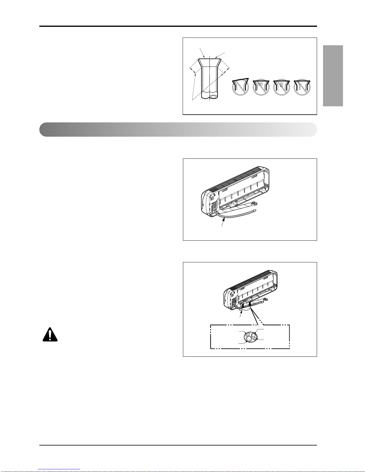
Check
1. Compare the flared work with figure below.
2. If flare is noted to be defective, cut off the
flared section and do flaring work again.
Preparing the indoor unit's piping and drain hose for installation through the wall.
1. Route the indoor tubing and the drain hose in
the direction of rear left or right
2.Tape the tubing, drain hose and the
connecting cable.Be sure that the drain hose
is located at the lowest side of the bundle.
Locating at the upper side can cause drain
pan to overflow inside the unit.
Inclined
Inside is shiny without scratches
Smooth all round
Even length
all round
Surface
damaged
Cracked Uneven
thickness
= Improper flaring =
Connection of piping - Indoor
Drain hose
Connecting
cable
Loop
Gas side
piping
Liquid side
piping
Drain hose
CAUTION: If the drain hose is
routed inside the room, insulate
the hose with an insulation
material* so that dripping from
"sweating"(condensation) will not
damage furniture or floors.
*Foamed polyethylene or
equivalent is recommended.
12 Multi Type Air Conditioner
Flaring Work and Piping Connection
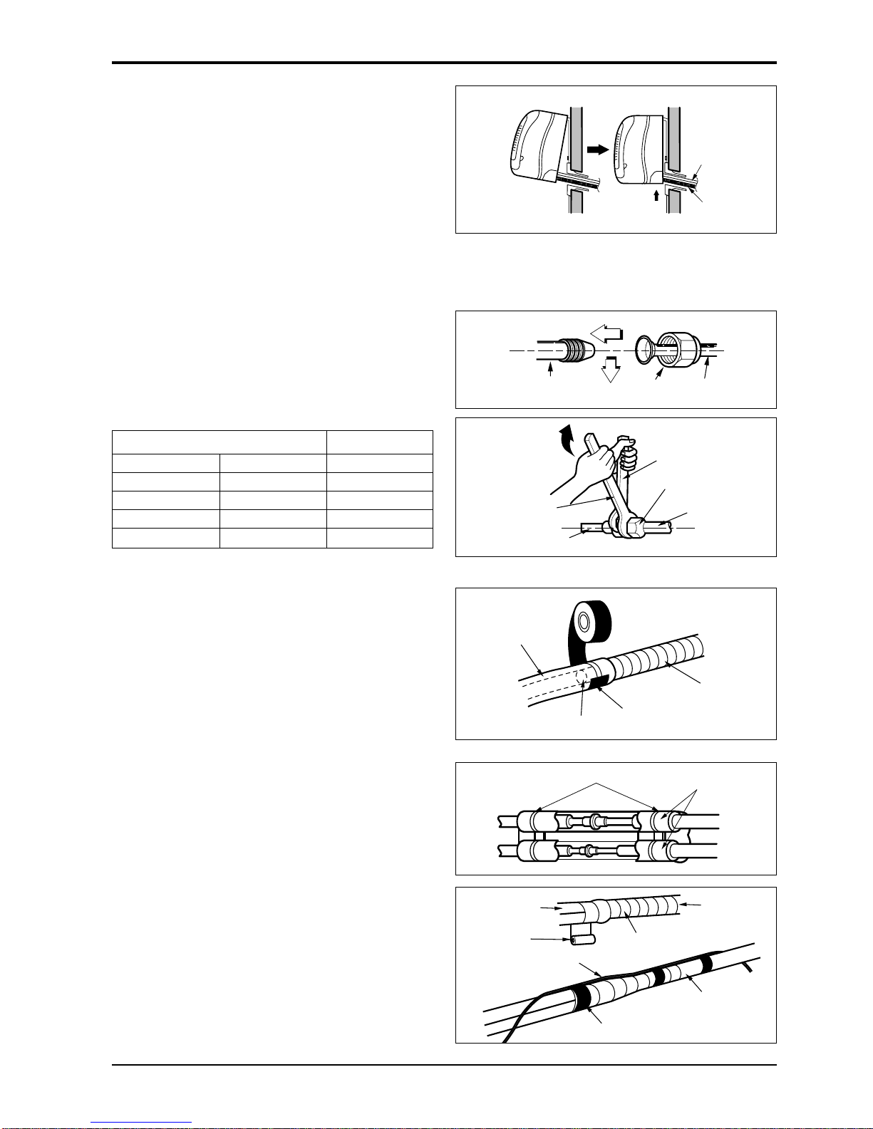
Indoor unit installation
1. Hook the indoor unit onto the upper portion of
the installation plate.(Engage the two hooks
of the rear top of the indoor unit with the
upper edge of the installation plate.) Ensure
that the hooks are properly seated on the
installation plate by moving it left and right.
Press the lower left and right sides of the unit
against the installation plate until the hooks
engage into their slots(clicking sound).
Connecting the pipings to the indoor
unit and drain hose to drain pipe
1. Align the center of the pipings and sufficiently
tighten the flare nut by hand.
2.Tighten the flare nut with a wrench.
3.When extending the drain hose at the indoor
unit, install the drain pipe.
Wrap the insulation material around
the connecting portion.
1. Overlap the connection pipe insulation
material and the indoor unit pipe insulation
material. Bind them together with vinyl tape
so that there is no gap.
2.Wrap the area which accommodates the rear
piping housing section with vinyl tape.
Drain hose
Connecting
cable
Indoor unit tubing Flare nut Pipings
Torque wrench
Indoor unit tubing
Spanner (fixed)
Connection pipe
Flare nut
mm inch kg.m
Ø6.35 1/4 1.8
Ø9.52 3/8 4.2
Ø12.7 1/2 5.5
Ø15.88 5/8 6.6
Outside diameter Torque
Vinyl tape(narrow)
Adhesive
Drain pipe
Indoor unit drain hose
Plastic bands
Insulation material
Vinyl tape(narrow)
Connection
pipe
Connecting cable
Vinyl tape
(wide)
Wrap with vinyl tape
Indoor
unit pipe
Pipe
Installation Manual 13
ENGLISH
Flaring Work and Piping Connection
3. Bundle the piping and drain hose together by
wrapping them with vinyl tape over the range
within which they fit into the rear piping
housing section.
Wrap with vinyl tape
Drain hose
Pipe
Vinyl tape(wide)
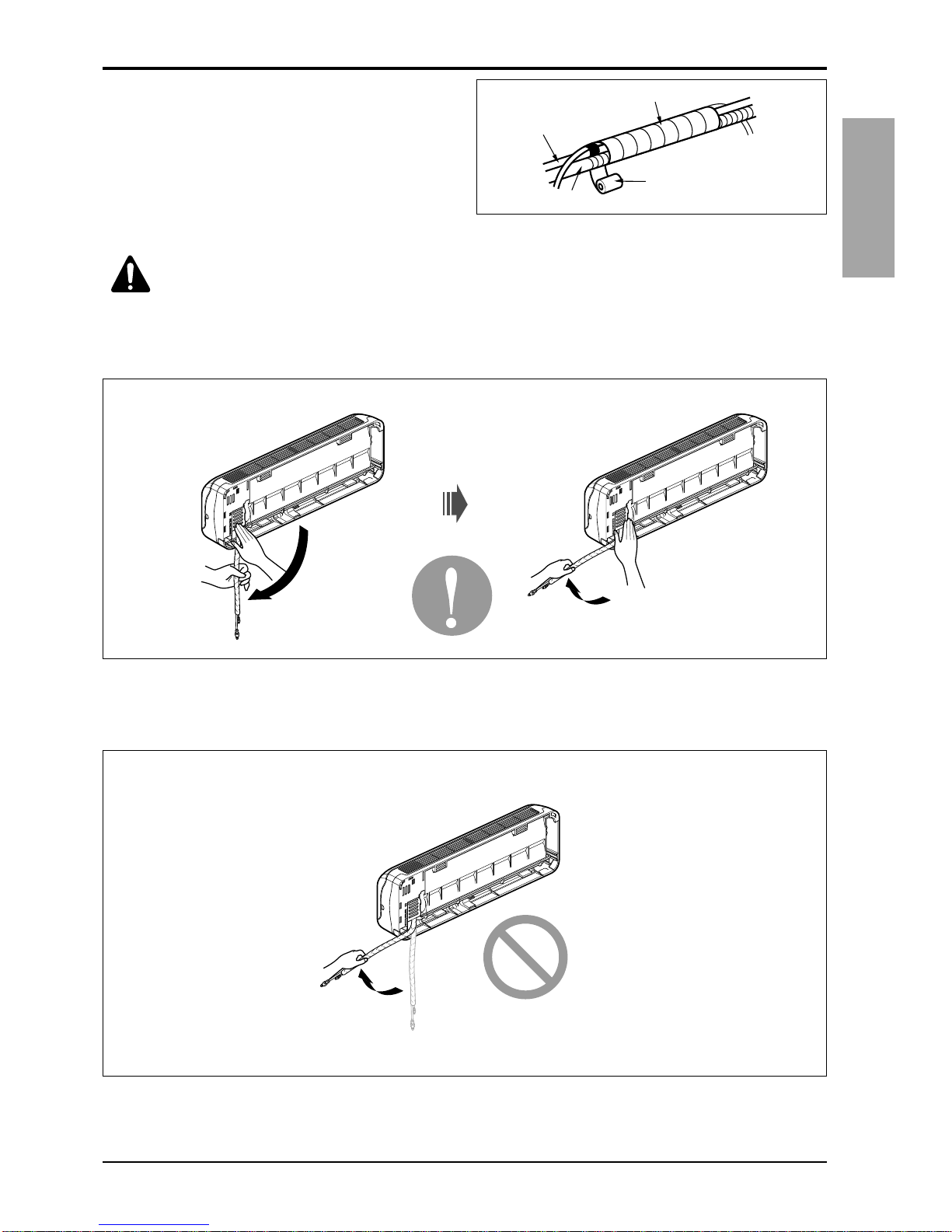
CAUTION: Installation Information (For right piping)
For right piping, follow the instruction below.
Good case
• Press on the upper side of clamp and unfold the tubing to downward slowly.
Bad case
• Following bending type from left to right could cause problem of pipe damage.
14 Multi Type Air Conditioner
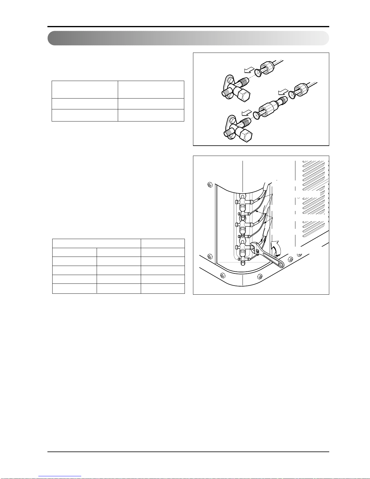
Flaring Work and Piping Connection
❈ When piping installation work, following
indoor units must be used the connector
which is in each indoor unit.
Align the center of the piping and sufficiently
tighten the flare nut by hand.
Finally, tighten the flare nut with torque wrench
until the wrench clicks.
• When tightening the flare nut with torque
wrench ensure the direction for tightening
following the arrow on the wrench.
A-UNIT
B-UNIT
C-UNIT
Gas side piping
Liquid side piping
Torque wrench
Outdoor unit
Connection of piping - Outdoor
Outside diameter Torque
mm inch kg.m
Ø6.35 1/4 1.8
Ø9.52 3/8 4.2
Ø12.7 1/2 5.5
Ø15.88 5/8 6.6
Indoor Capacity
(Btu/h)
24K
Liguid Side Ø6.35 → Ø9.52
Gas Side Ø12.7 → Ø15.88
 Loading...