

LG L1710LT Owner's Manual

Order Number
: GETEC-C1-11-045
FCC Part 15 subpart B
Test Report Number
: GETEC-E3-11-015 Page 1 / 1
EUT Type: LED LCD Monitor
FCC ID.: BEJN1710LTU
APPENDIX G
: USER’S MANUAL

www.lg.com
OWNER’S MANUAL
MULTI POS MONITOR
L1710LT
Please read this manual carefully before operating the
your set and retain it for future reference.
MULTI POS MODELS
ENG
ENGLISH

2
ENG
ENGLISH
TABLE OF CONTENTS
CONTENTS
3 ASSEMBLING AND PREPARING
3 Unpacking
4 Parts and buttons
5 Setting up the Monitor set
5 - Mounting on a table
6 - Basic Adjustments of the Stand
7 - Detaching the Stand
8 - Mounting on a wall
9 USING THE MONITOR SET
9 Connecting to a RGB Cable
9 - Using the PC
9 - Using the MAC
10 To Use Touch Screen
10 - USB cable for the touch screen
11 CUSTOMIZING SETTINGS
11 Accessing main menus
12 Customizing settings
12 - SETUP settings
13 - COLOR settings
14 - TRACKING settings
15 - SETUP settings
16 - F·ENGINE settings
17 TROUBLESHOOTING
19 SPECIFICATIONS

3
ENG
ENGLISH
ASSEMBLING AND PREPARING
ASSEMBLING AND PREPARING
Unpacking
Check your product box for the following items. If there are any missing accessories, contact the local
dealer where you purchased your product. The illustrations in this manual may differ from the actual product
and accessories.
y
Do not use any pirated items to ensure the safety and product life span.
y
Any damages or injuries by using pirated items are not covered by the warranty.
y
The accessories supplied with your product may vary depending on the model.
y
Product specifications or contents in this manual may be changed without prior notice due to upgrade
of product functions.
y
User must use shielded signal interface cables (D-sub 15 pin cable) with ferrite cores to maintain
standard compliance for the product.
CAUTION
NOTE
Power Cord
CD(Owner's Manual/
Software Installation)
Easy Setup Guide Cards
Adaptor
4
ENG
ENGLISH
ASSEMBLING AND PREPARING
y
You can set the Power indicator to on or off by selecting OPTION in the main menus.
NOTE
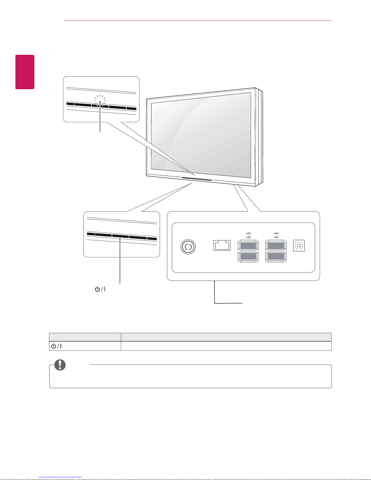
Parts and buttons
button Description
(Power Button)
Turns the power on or off.
AC-IN LAN SERVICE
Power Indicator
y
Lighting On: Turned on
y
Lighting Off: Turned off
Connection panel ( See p.4)
(Power Button)
5
ENG
ENGLISH
ASSEMBLING AND PREPARING
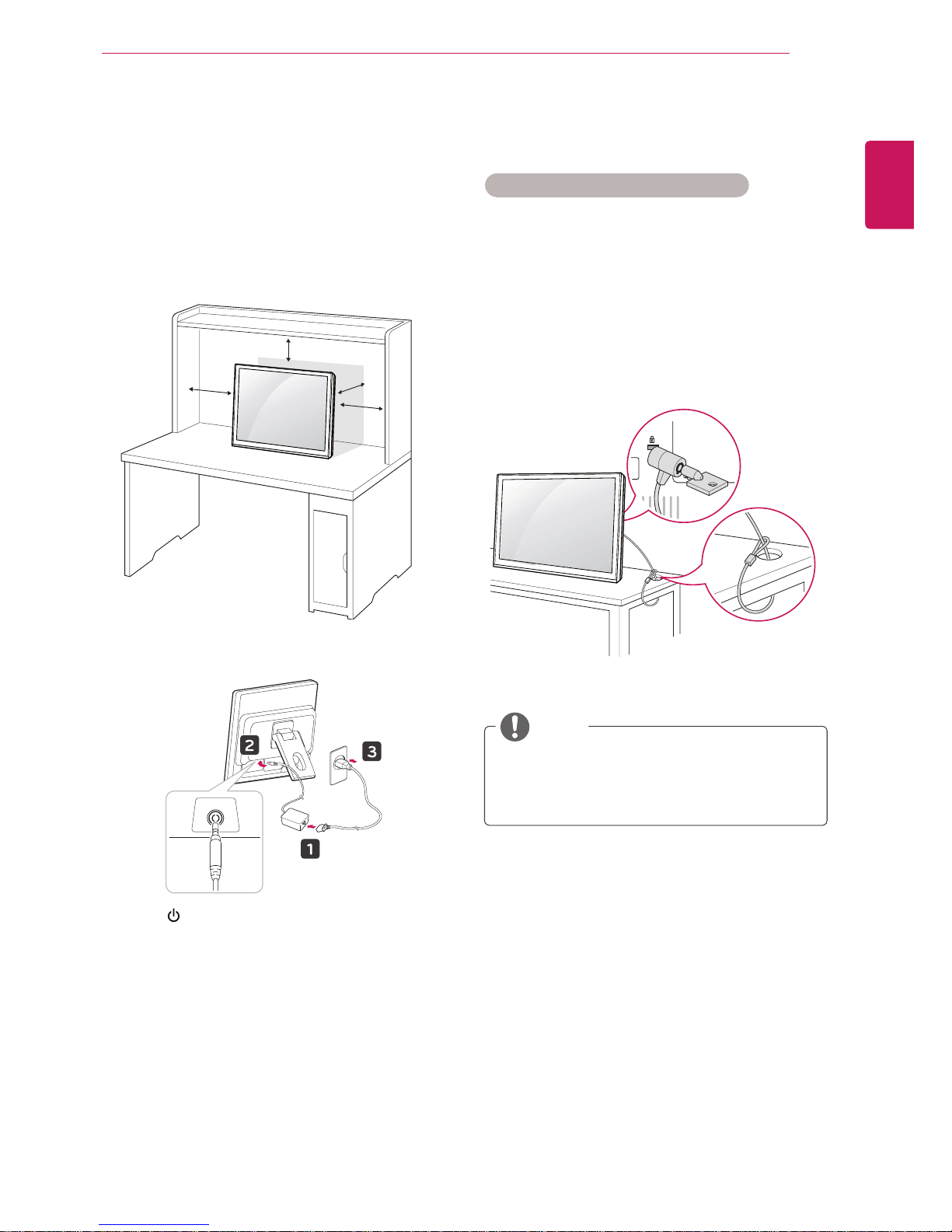
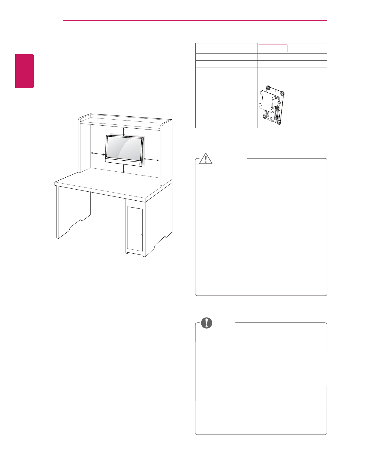
Setting up the Monitor set
Mounting on a table
1
Lift and tilt the Monitor set into its upright
position on a table.
Leave a 10 cm (minimum) space from the wall
for proper ventilation.
2
Connect the Power Cord to a wall outlet.
3
Press button on the front switch panel to
turn the power on. When monitor power is
turned on, the 'Self Image Setting Function' is
executed automatically.
10 cm
10 cm
10 cm
10 cm
AC-IN
Using the Kensington security system
The Kensington security system connector is
located at the back of the Monitor set. For more
information of installation and using, refer to the
manual supplied with the Kensington security
system or visit
http://www.kensington.com
.
Connect the Kensington security system cable
between the Monitor set and a table.
The Kensington security system is optional.
You can obtain additional accessories from
most electronics stores.
NOTE
6
ENG
ENGLISH
ASSEMBLING AND PREPARING
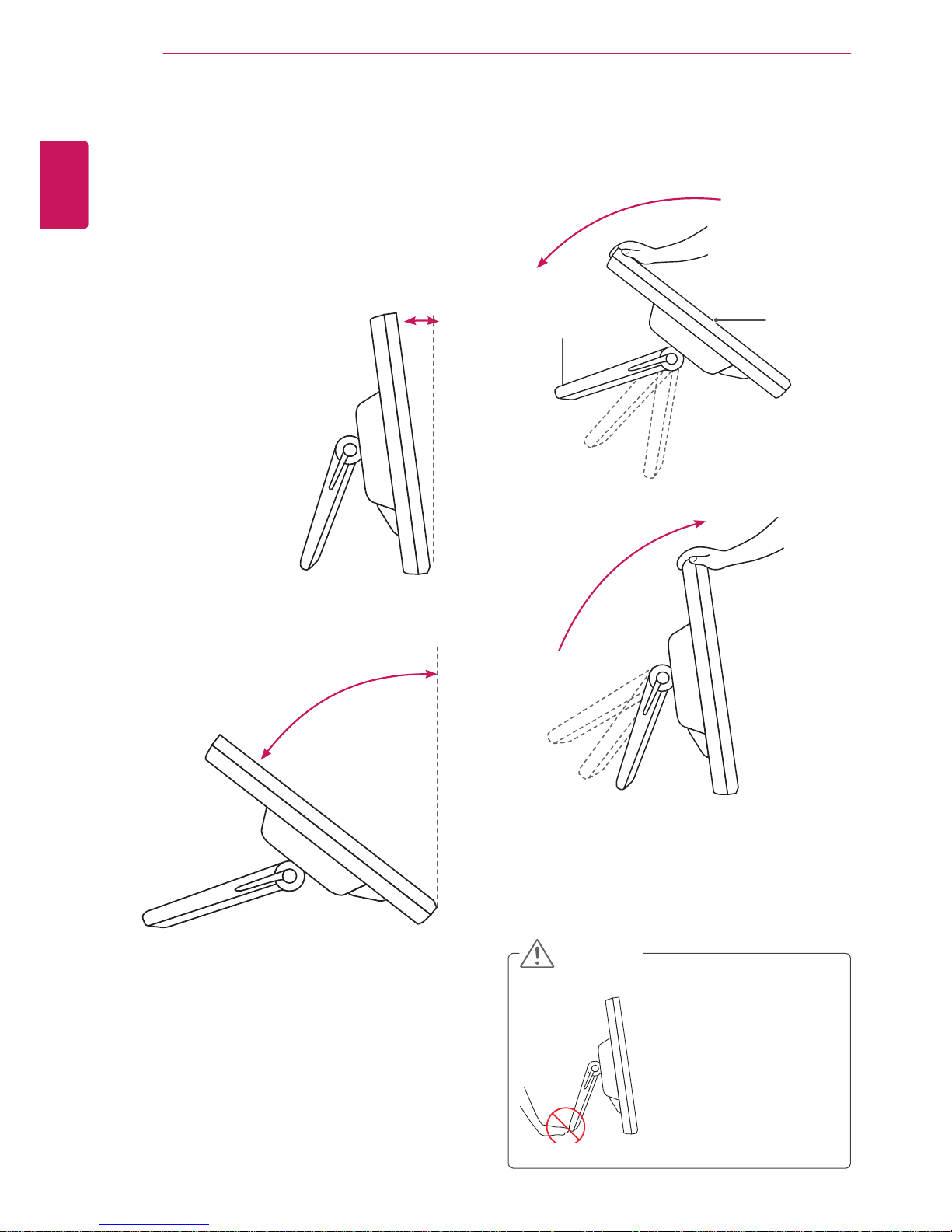
Basic Adjustments of the Stand
1
Adjust the angle of the panel as follows.
y
Tilt Range : 15° to 66°
Do not push the stand
with basic adjustment
to the direction of the
panel. The product may
fall down to hurt people,
or cause product
disorder or screen
damage.
CAUTION
y
Push back the panel to the end, and use
from the point that it automatically returns.
15°
66°
Panel
Stand
7
ENG
ENGLISH
ASSEMBLING AND PREPARING
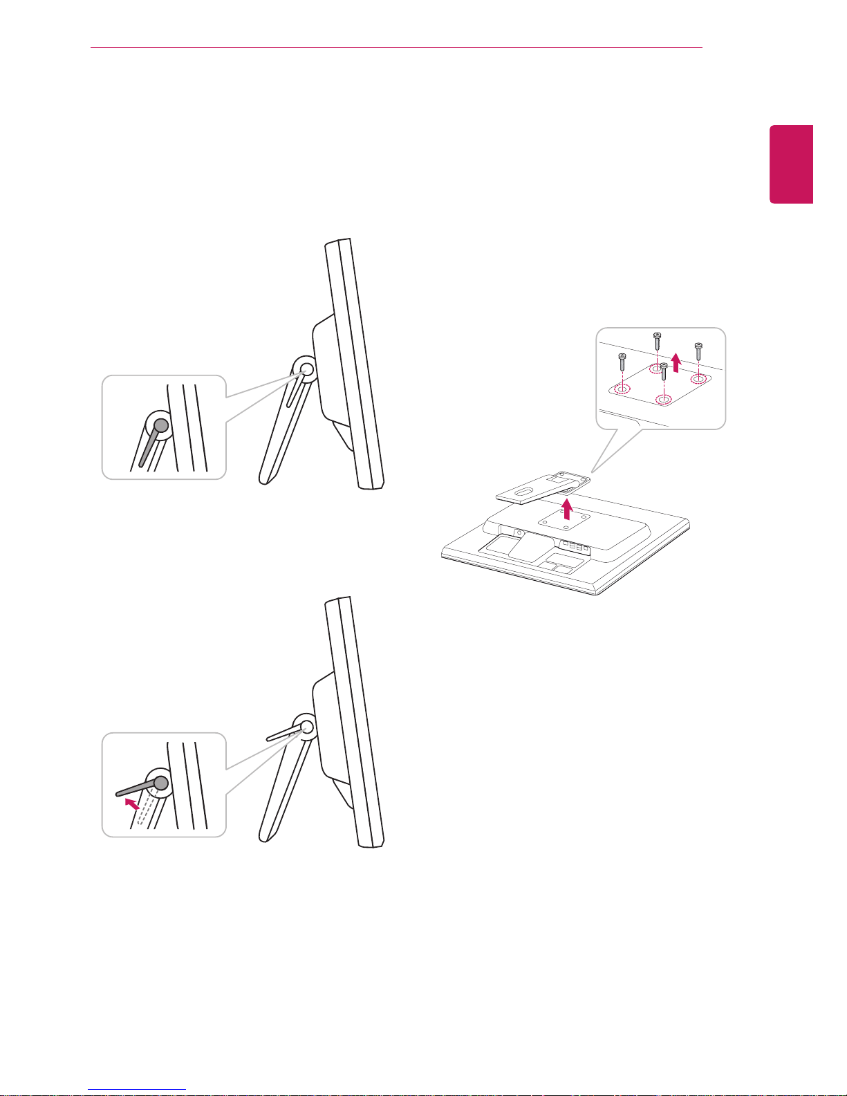
2
After adjusting the angle of the panel for
convenience, lock with the locking handle to.
Prevent the product from moving when users
touch the screen.
y
The state which the stand locking handle is
released
y
The state which the stand locking handle is
locked
Detaching the Stand
This Monitor set satisfies the specifications of the
Wall mount plate or the interchange device.
1
Place the monitor with its front facing
downward on a soft cloth.
2
Separate the head and the stand with the use
of a screwdriver.
3
Remove 4 screws and pull out the Stand from
the Monitor set.
8
ENG
ENGLISH
ASSEMBLING AND PREPARING
y
Disconnect the power cord first, and then
move or install the Monitor set. Otherwise
electric shock may occur.
y
If you install the Monitor set on a ceiling or
slanted wall, it may fall and result in severe
injury. Use an authorized LG wall mount
and contact the local dealer or qualified
personnel.
y
Do not over tighten the screws as this may
cause damage to the Monitor set and void
your warranty.
y
Use the screws and wall mounts that
meet the VESA standard. Any damages
or injuries by misuse or using an improper
accessory are not covered by the warranty.
y
Use the screws that are listed on the VESA
standard screw specifications.
y
The wall mount kit includes an installation
manual and necessary parts.
y
The wall mount bracket is optional. You can
obtain additional accessories from your local
dealer.
y
The length of screws may differ depending
on the wall mount. Be sure to use the proper
length.
y
For more information, refer to the
instructions supplied with the wall mount.
CAUTION
NOTE
Model
N1710LT
VESA (A x B) 75 x 75
Standard screw M4
Number of screws 4
Wall mount bracket
(optional)
RW120
Mounting on a wall
For proper ventilation, allow a clearance of 10
cm on each side and from the wall. Detailed
installation
instructions are available from your dealer, see the
optional Tilt Wall Mounting Bracket Installation and
Setup Guide.
If you intend to mount the Monitor set to a wall,
attach Wall mounting interface (optional parts) to
the back of the set.
When you install the Monitor set using the wall
mounting interface (optional parts), attach it
carefully so it will not drop.
Please use VESA standard as below.
y
784.8 mm (30.9 inch) and under
* Wall Mount Pad Thickness : 2.6 mm
* Screw : Φ 4.0 mm x Pitch 0.7 mm x
Length 10 mm
y
787.4 mm (31.0 inch) and above
* Please use VESA standard wall mount pad
and screws.
10 cm
10 cm
10 cm
10 cm
9
ENG
ENGLISH
USING THE MONITOR SET
y
The display link and EST network USB setting utility should already be installed before connecting
the power cable for the 2nd POS (monitor).
y
As of April 2011, the host POS authorized by the network POS is the HANASIS MICUS37 model.
For additional models, visit http://networkmonitor.lge.com.
y
The warranty does not cover any damage caused by the use of products other than the authorized
host POS.
y
The LAN and USB cables are optional. You can purchase them from an electronics store, online
stores, or your local LG stockist.
y
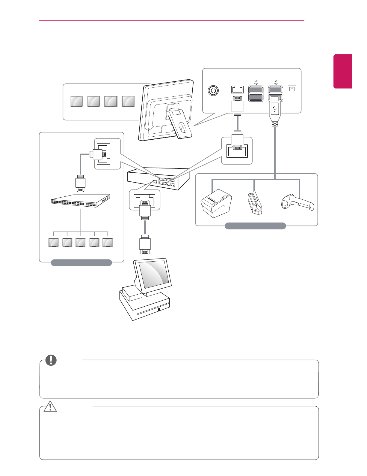
You can connect up to five monitors to the host POS. If you need to connect more monitors than the
number of ports in the router, use the switching hub to connect.
CAUTION
NOTE
USING THE MONITOR SET
Connecting to a LAN Cable
AC-IN LAN SERVICE
Router
USB Cable
(Not included)
LAN Cable
(Not included)
LAN Cable
(Not included)
LAN Cable
(Not included)
LAN Cable
(Not included)
Not included
Option
2nd POS (Monitor)
2nd POS (Monitor)
Switching
hub
Host POS
1
Connect the router or switching hub to the
monitor with a LAN cable.
2
Remove the power cable from the 2nd POS
(monitor).
3
Install the display link and EST network USB
setting utility onto the host POS, and then
reboot it.
4
Connect the power cable to the 2nd POS
(monitor).
5
Install the LG network service driver, and check
that the screen blinks as many times as the
number of 2nd POSs (monitors), and then
reboot it.
6
Check that the 2nd POSs (monitors) operate
normally and also that the touch response
works properly.
7
Install SoftXpand Xpress.
 Loading...