

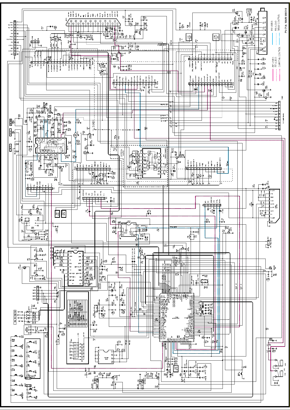
Page 1
Page 2
Page 3
Page 4
Page 5
Page 6
Model
FACTORY.
Buyer
EFFECTIVE DATE
Subject
SERVICE BULLETIN
KI-14U71
KI-14U71X
KI-20U71
KI-20U72X
GB000001
31/05/1998
Improvement of the reliability
EFFECTIVE FROM(SERIAL NO.)
No. : VSB-85030
Date : 08/06/1998
From the shipment
on June 1998
No. LOC NO.
Before Change After Change
PART NO. DESC./SPEC. PART NO. DESC./SPEC.
1 4814V00016A
SHIELD
BUTTOM
4814V00016B
SHIELD
MAIN 1 SBHG-1 . BOTTOM
Reason Of Change
Symptom : "HUM" in sound when playing a tape recorded in SET.
Countermeasure : Add a silicon shield plate to SHIELD BOTTOM.
** FILE THIS SERVICE BULLETIN WITH YOUR SERVICE MANUAL
NOTE(**) : INTERCHANGEABILITY CODE KEY-WORD CODE
Parts Set
Original
A
New
Original
B
New
Original
C
New
Original
D
New
Original or new parts may be used in early or
Early
late production sets.
Late
Use original parts until exhausted, then stock
new parts.
Original parts may be used in early production
sets only.
Early
New parts may be used in early or late production
sets.
Late
Use original parts where possible, then stock new
parts.
New parts only may be used in early or late
Early
production sets.
Late
Stock new parts.
Original parts only may be used in early
Early
production sets.
New parts may be used in late production sets
Late
only.
Stock original and new parts.
1. To improve performance
2. To improve productivity
3. To improve reliability
4. Change of material or
dimension
5. Addtion
6. Deletion
7. Correction
Note
K-
CODE
B 3
Remark
CHIEF ENGINEER ,
Page 7
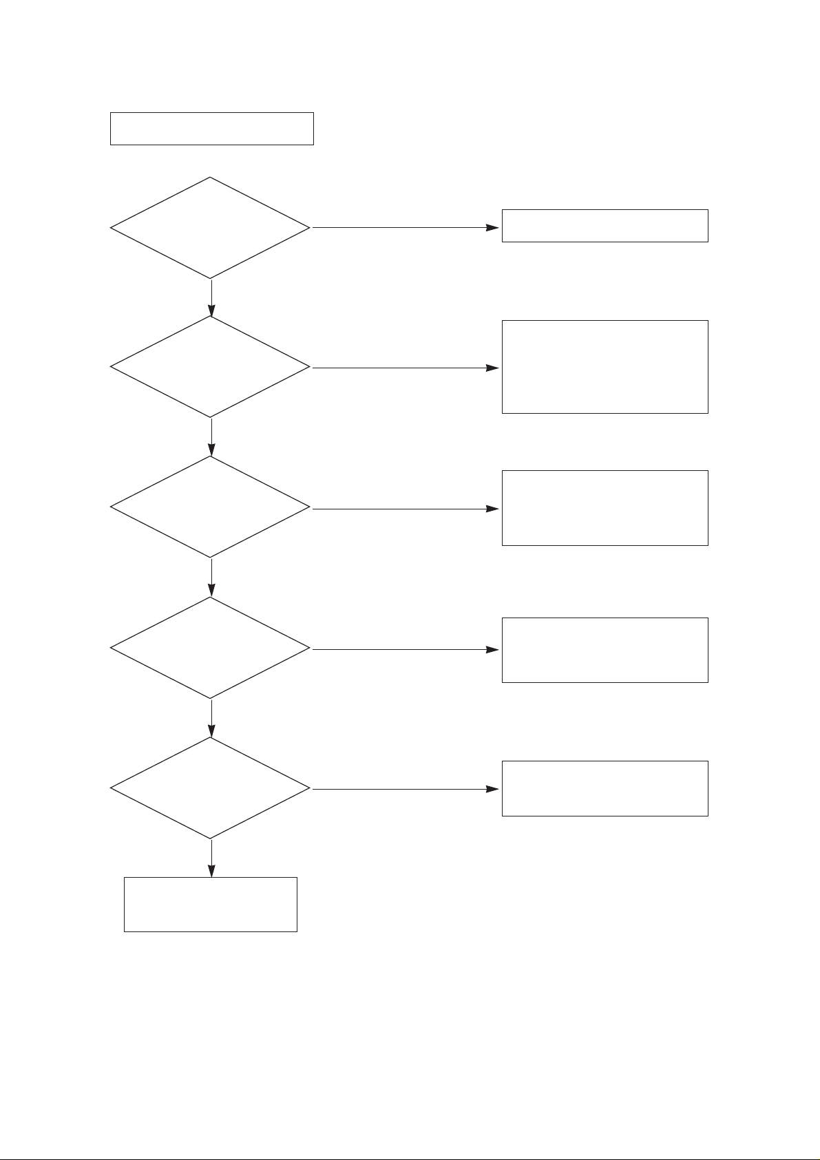
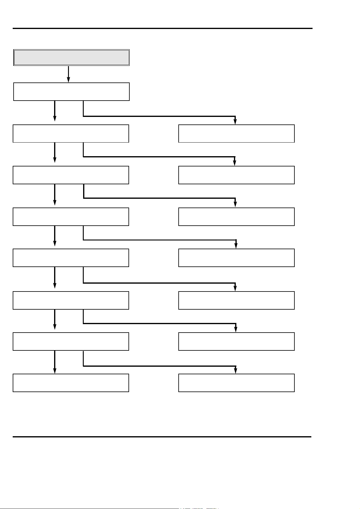
1
Is there about 6V
at pin 9 of P804?
YES
Is there about 11V
at '+' terminal
of C856?
YES
Is there about 6.1V
at pin 9 of IC801?
YES
Is there voltage at
pin 9 of T801?
YES
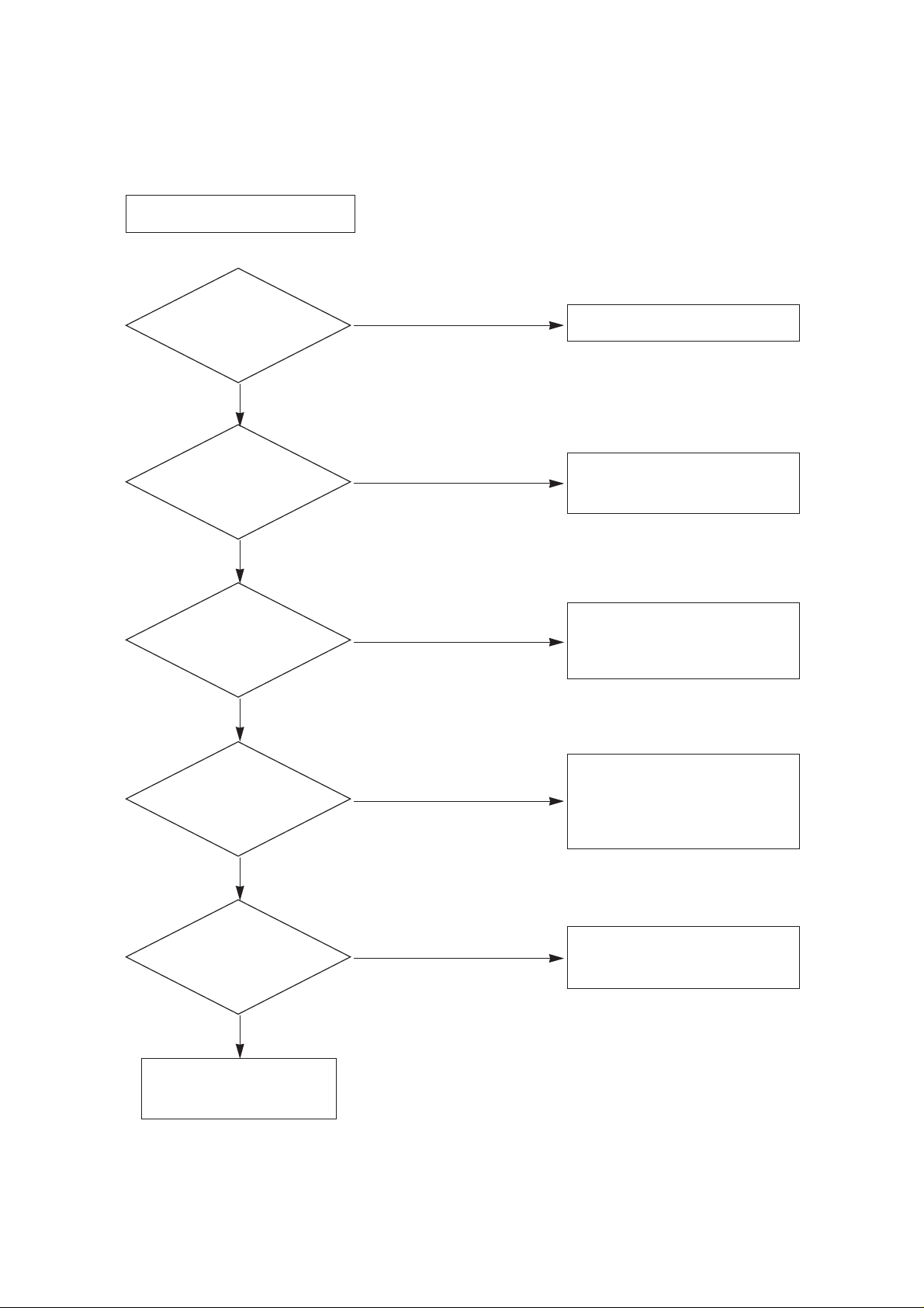
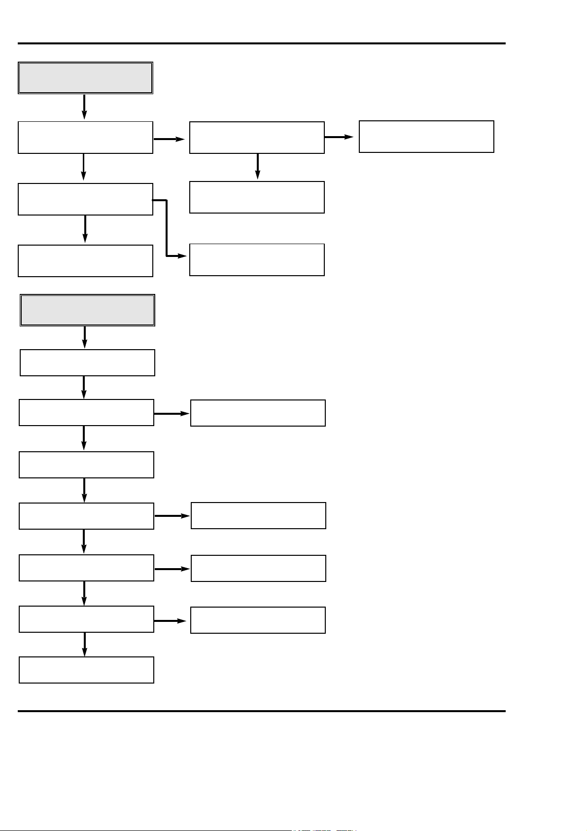
NO POWER : NO STAND-BY
Replace the Fuse
Check the 6V Line
of MAIN 1 BOARD
Check if the
Fuse is O.K.?
YES
NO
Check/Replace
D801, D802, 803, 804, R801, C807.
NO
Check/Replace
D806, Q801, R807, ZD801, C814,
IC801.
NO
¡ Check/Replace FR851, D852,
C856, Q860, Q861, Q862,
ZD860, ZD861, R874.
¡ Check the pin 11 of P804 :
'LOW"
NO
Check/Replace
R863, IC857, D858, R877, C875
NO
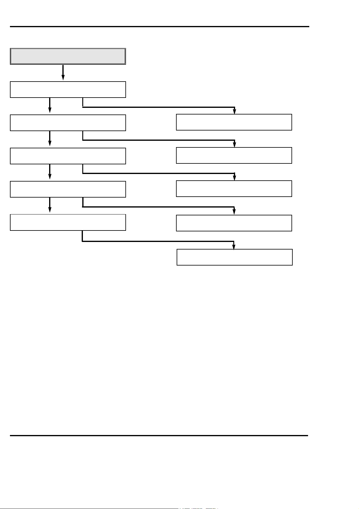
TROUBLE SHOOTING
Page 8
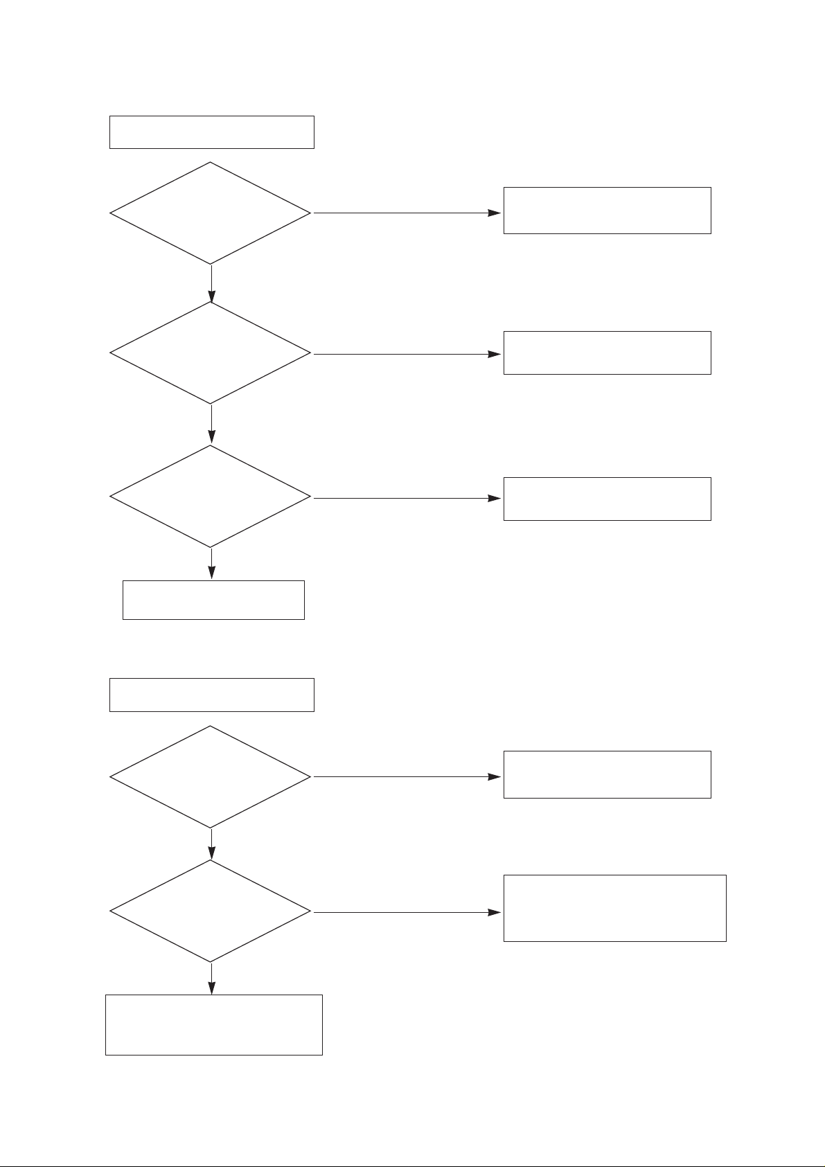
2
Is there about 115V
at '+' terminal of C865?
YES
Is there about
6V at pin 9 of P804?
YES
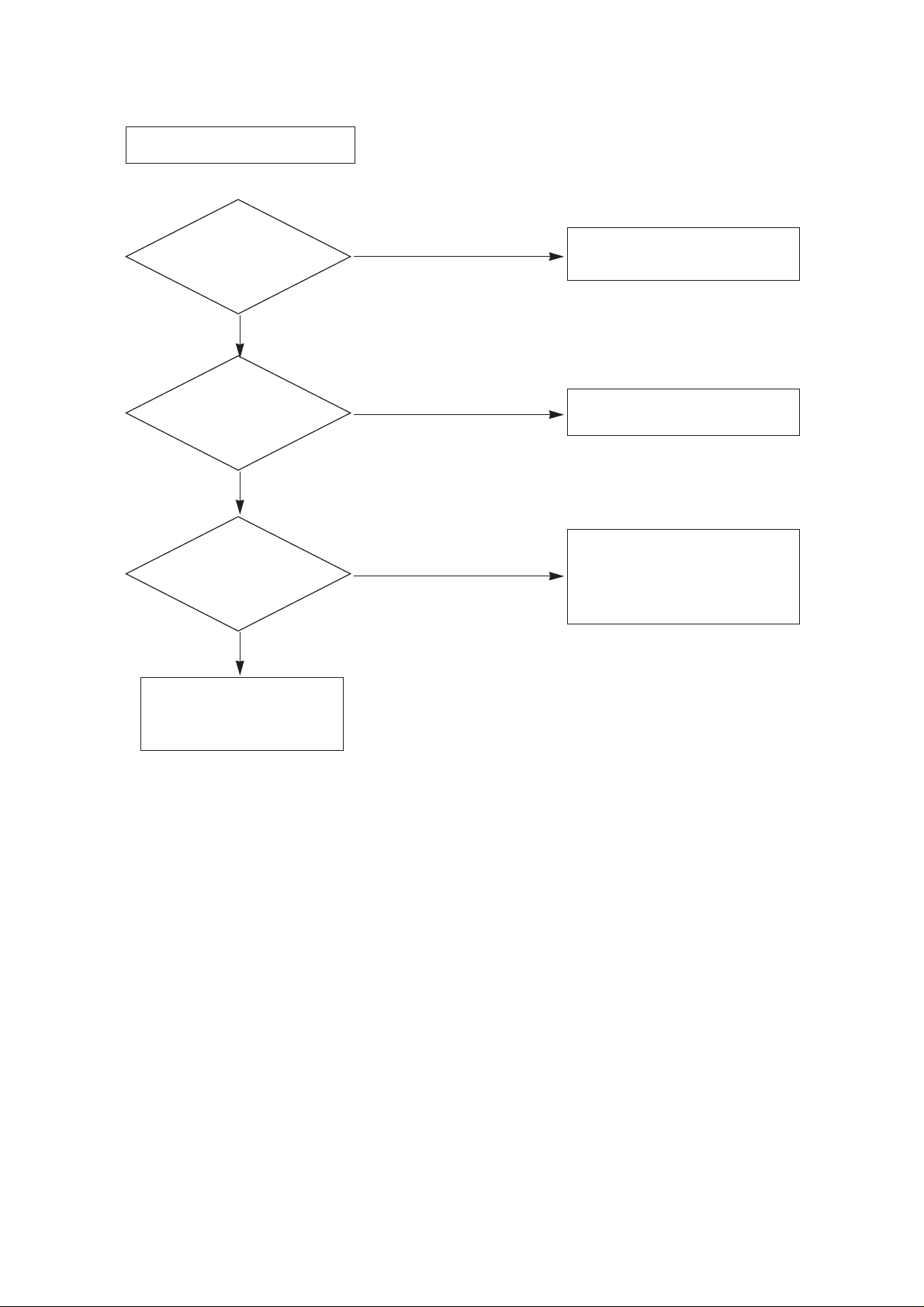
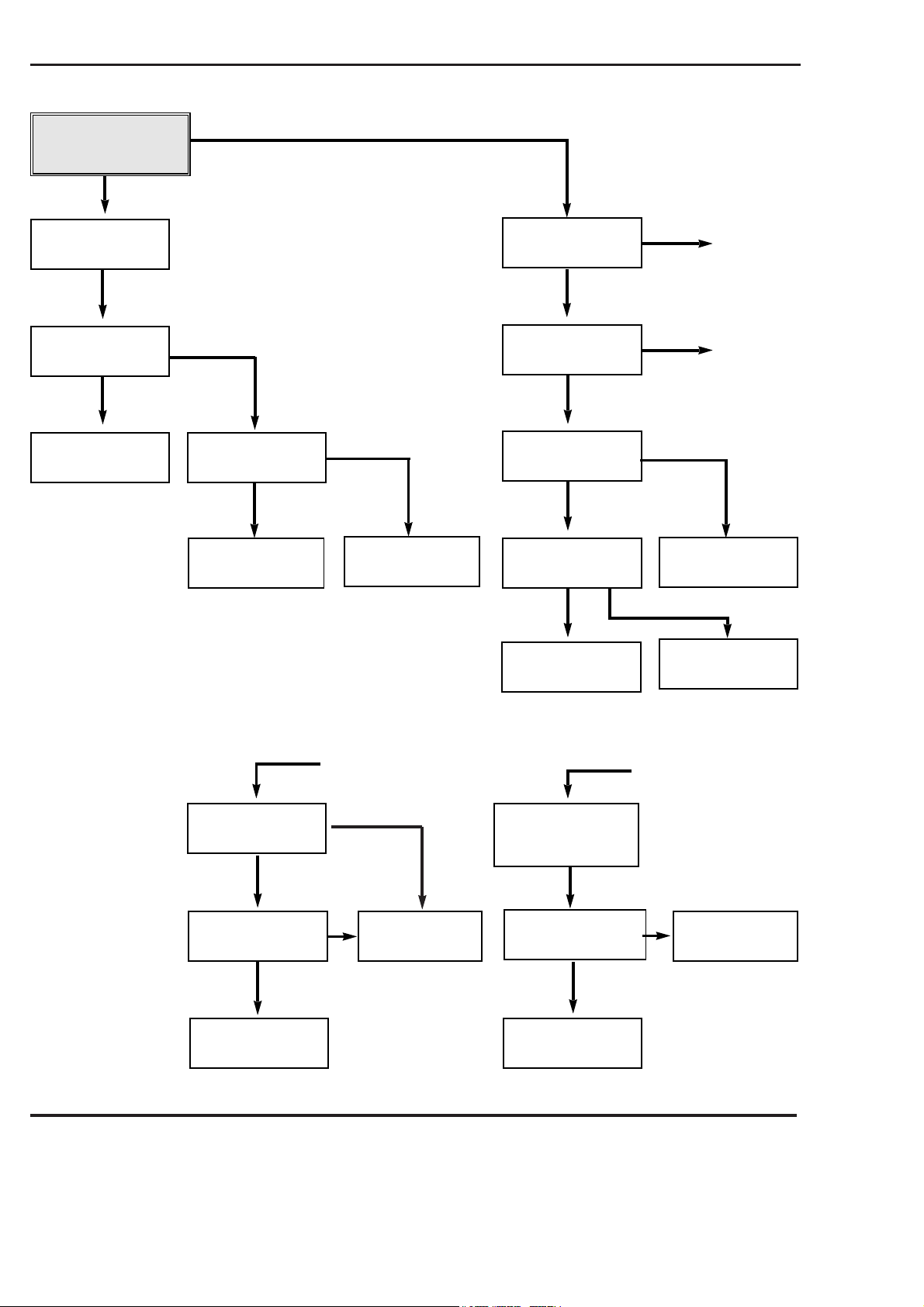
NO POWER : NO MONITOR ON
Go to NO POWER (NO ST-BY)
BLOCK
Go to NO RASTER BLOCK
Check T701, Q781 and go to
NO RASTER BLOCK
Check the
NO POWER(NO ST-BY)
BLOCK
YES
NO
Check the pin 10 of P804 ; "HIGH"
NO
¡ Check/Replace D851, L851,
C860, IC851.
¡ Check the pin 10 of P804 :
'HIGH"
NO
Page 9
3
Is there about
6.3VAC at HEATER of CPT
SOCKET?
YES
Does the waveform
appear at the collector
of Q781?
YES
Does the square
waveform appear at pin 1 of
P805?
YES
Is there about 8V
at pin 6 of P805?
YES
NO RASTER
Go to NO POWER BLOCK
Go to NO PICTURE BLOCK
Is there about 115V
at pin 3 of T701?
YES
NO
¡ Check/Replace F852, D850,
C857, R899, IC853, C863.
¡ Check the 8V LINE of VCD
BOARD
NO
¡ Check the H-OUT LINE of VCD
BOARD.
¡ Check/Replace IC501 of VCD
BOARD.
NO
Check/Replace Q782, T781, R783,
R787, Q781.
NO
Check/Replace T701, 5PIN
CONNECTOR, FR2901, FR2902
(14" : FR1901)
NO
Page 10
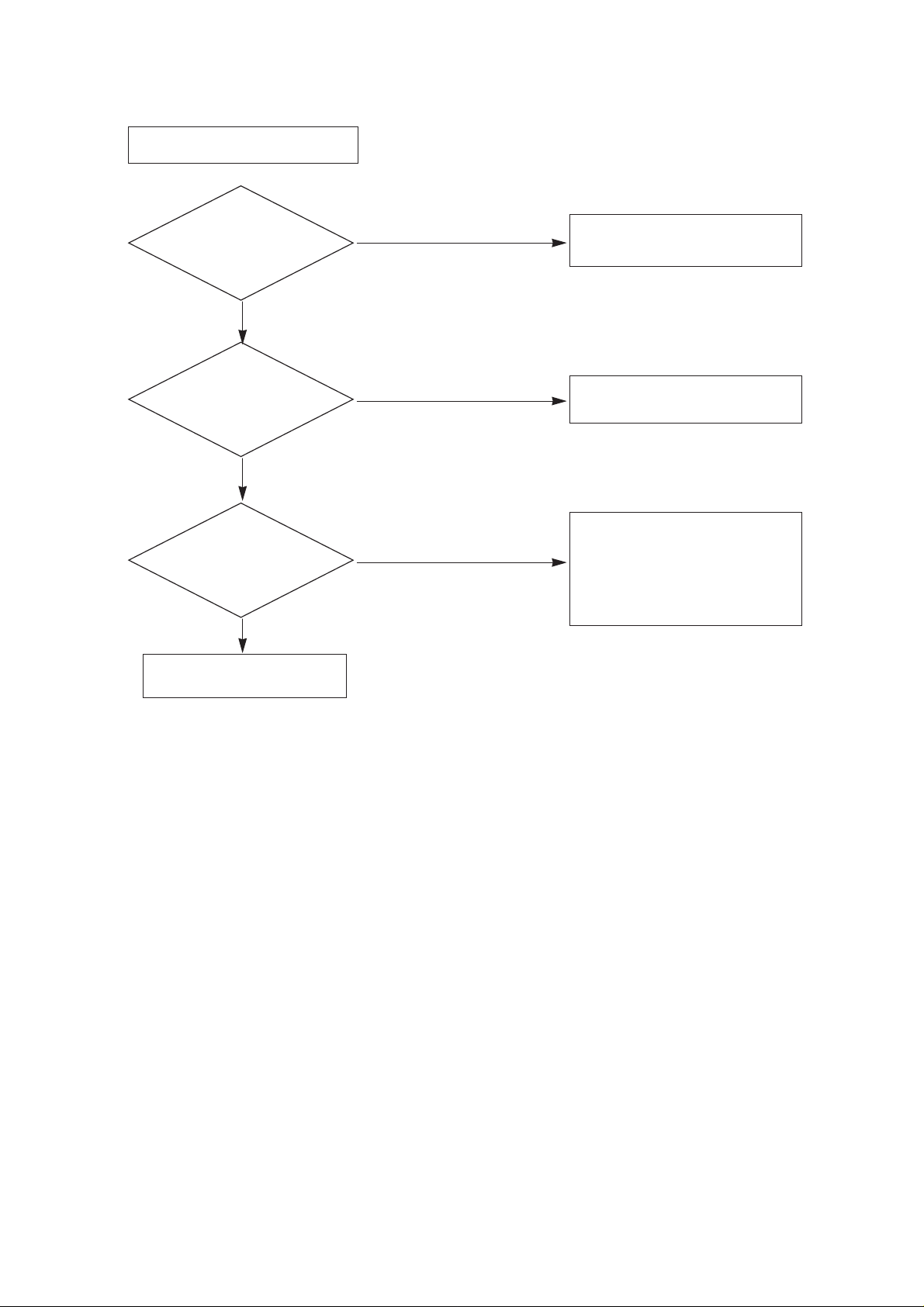
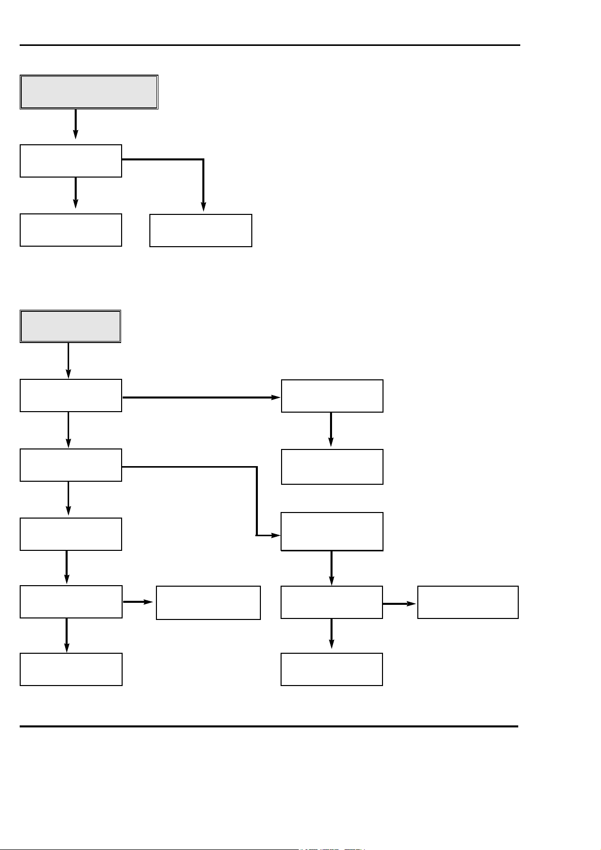
4
Is there about
44V at pin 6 of IC701?
YES
Is there about
15V at pin 3 of
IC701?
YES
V. Deflection ERROR
Check the vertical part of VCD
BOARD
Check/Replace IC701
Does the V-A, V-B
signal appear at pin 4, 7
of P805?
YES
NO
Check/Replace FR702, D702, C704,
L731
Check;/Replace FR701, D701, C708,
L732, C734.
NO
Is there about
200V at pin 1 of P2901B?
(14" : P1901B)
YES
NO PICTURE
Check the CVBS line of VCD BOARD
(Refer to VCD BLOCK DIAGRAM)
¡ Check/Replace IC2901.
(14" : IC1901)
¡ Check screen voltage
Does the RGB signal
appear at pin 3, 5, 7 of
P2902? (14" : P1902)
YES
NO
Check/Replace FR704, D703, C702,
T701, 5PIN CONNECTOR, L2901,
R2924 (14" : L1901, R1924)
NO
NO
Page 11
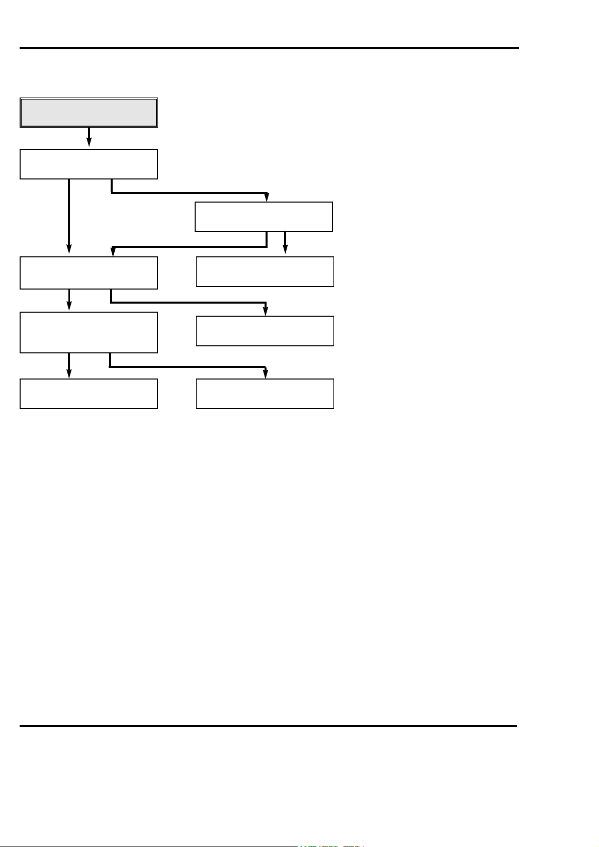
5
Does the sound
signal appear at pin 4
of IC601?
YES
Does the sound
signal appear at pin 9
of P805?
YES
NO SOUND
Check/Replace FR854, D855, IC601.
Check/Replace speaker,
speaker connector.
Is there about
25V at pin 5
of IC601?
YES
NO
Check the Audio source line of
VCD BOARD
¡ Check the voltage at collector of
Q601.
¡ Check/Replace IC601, external
components of IC601.
NO
NO
Page 12
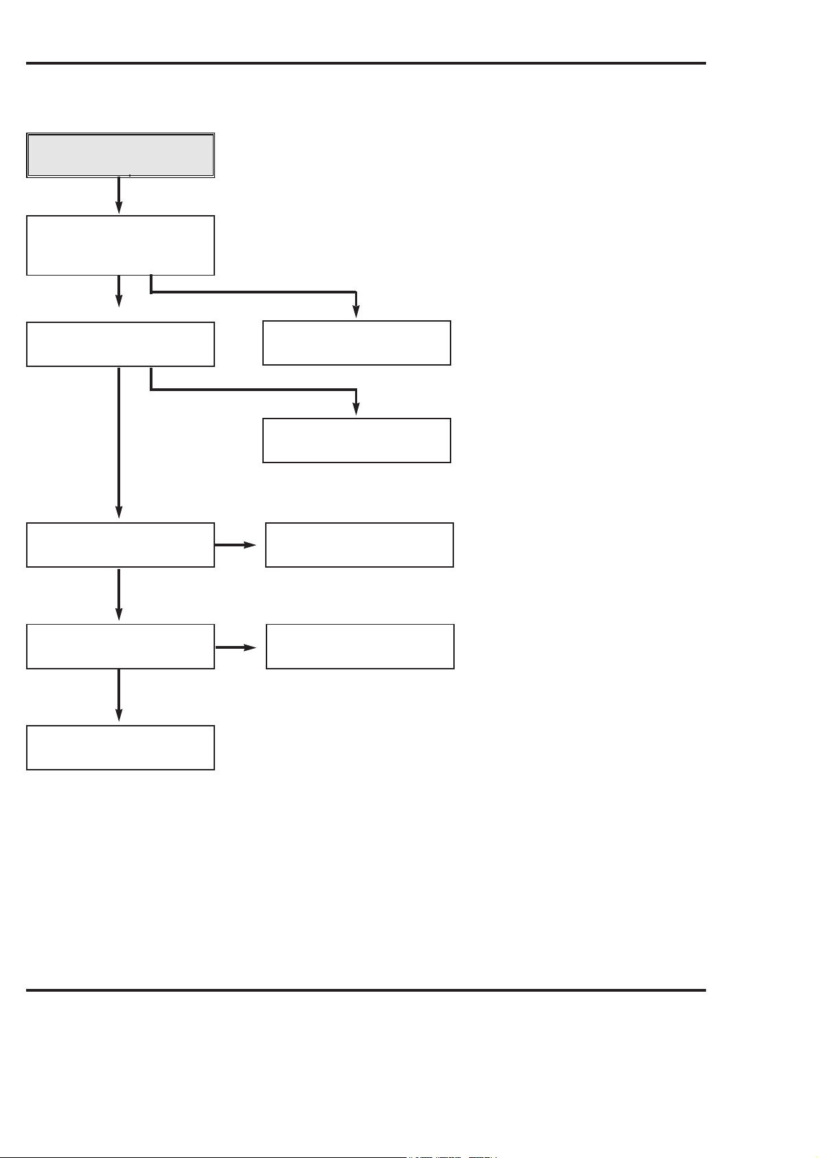
MECHANISM TROUBLESHOOTING GUIDE
1.Deck Mechanism
A.
Auto REW doesn't work.
YES
Is the output of END senser
of supply side "L"?
Is the supply end sensor less than
3.5V ("L")
YES
NO
Is the voltage drop across IR LED
between 0.8
~1.5V?
NO
Is LED-Prism OK?
YES
NO
Check the system (u-com).
Replace LED.
Check the 5VA supply, replace
LED Prism.
YES
Is the Prism housing damaged? Replace Prism.
NO
YES
Replace Photo Tr.
NOTES:
1)Auto REW takes place when the supply end sensor is "H" high.
2)"H"=voltage greater than 3.5V, "L"=voltage between 0.7~1.0V.
4-27
Page 13
MECHANISM TROUBLESHOOTING GUIDE
AUTO STOP.
YES
In auto stop is the pinch roller in
contact with the capstan shaft.
YES
Are there T/up and supply reel
pulses.
YES
Check the Syscon, u-COM.
No cassette loading.
YES
Insert the cassette.
YES
Does the cassette door lever S/W
work normally.
NO
NO
NO
Is the output of DFG, DPG OK?
YES
Check Servo, Syscon.
Replace Reel Sensor.
Check Housing Assembly.
NO
Replace Drum Motor.
YES
Is the output of F/L S/W"H"?
YES
Is the mode SW in the ULC
position. (tape unloaded)
NO
Does Capstan Motor turn?
YES
Did the H1 lever change position.
YES
Check Housing Ass'y.
YES
NO
NO
Refer to 1. Mechanism and Mode
Switch Alignment check (Page 4-16)
Check Capstan Motor.
Refer to Page 4-8 item 11.
4-28
Page 14
MECHANISM TROUBLESHOOTING GUIDE
D.
In PB mode Tape
Presence not sensed.
YES
Is the Pinch Roller
attached to the
Capstan Motor Shaft?
YES
Does the T/Up
Reel turn?
YES
Check the clutch and
the Idler Assembly.
NO
NO
Is the Belt OK?
YES
Check T/up Reel
and replace.
NO
Replace the Belt.
Does the Capstan
Motor turn?
YES
Does the Drum
Motor turn?
YES
Are there DPG,
DFG Pulses?
YES
Are the T/Up Supply
Reel SensorsOK?
NO
¨Í
NO
¨Î
NO
Replace Drum
Motor.
¨Î
Is the Vcc voltage of the
Drum Motor normal?
YES
Is the terminal voltage
of the Drum Motor
more than 2V?
YES
Replace the
Drum Motor.
NO
NO
NO
Check Servo.
YES
Check Servo, Syscon.
NO
¨Í
Is the voltage supplied
to the Capstan Motor
Vcc1, Vcc2 each?
YES
Does terminal voltage of
Capstan Motor supplied
more than 4V?
YES
Replace the
Capstan Motor.
Replace Reel
Sensor.
NO
Check Servo,
Power.
4-29
Page 15
YES
MECHANISM TROUBLESHOOTING GUIDE
In Eject mode, the Tape
will not eject.
Are the T/Up and Supply
End Sensors OK?
Replace the F/L S/W.
Replace End Sensor.
No F/R modes.
Does the Capstan Motor
rotate?
Do the T/Up, Supply
Reel rotate?
Replace Reel Sensor.
Capstan motor stopped
due to jammed
mechanism?
Is the normal voltage
supplied to the Capstan
Motor Vcc1, Vcc2.?
Eject Key-in.
Is the mode SW
assembled correctly
(refer to Pages 4-16.)
Does terminal voltage of
Capstan Motor supply
side more than 4V?
Replace the
Capstan Motor.
Check Servo, Power.
Check the clutch, Lever
Ass'y F/R and Idler Ass'y.
Is the present mode,
F/R Mode?
NO
NO
NO
NO
YES
YES
YES
YES
NO
YES
YES
YES
YES
YES
4-30
E.
Page 16
MECHANISM TROUBLESHOOTING GUIDE
2. Front Loading Mechanism
A.
Cassette cannot be inserted.
Does the Lever Switch work?
YES
Is 5V applied to the ¥-COM
Vcc port.
YES
Is 5V applied to CST switch port of
u-COM
YES
Check the syscon Part.
NO
NO
?
NO
Is the Cassette Lever/Spring
Switch damaged or omitted?
NO
Replace or add the Lever/Spring
Switch.
Check the Power Part.
Replace the Cassette Switch.
YES
4-31
Page 17
Cassette will not load.
Does the CST insert?
Does the lid opener work?
Does the Gear Cam F/L work?
Does the lid opener work?
Does the Arm Assembly F/L work?
Does the Capstan Motor work?
Does the Holder Assembly Cassette move
the Arm Assembly F/L?
Replace the Front Loading
Mechanism Assembly.
Check the Gear H1 position on the Deck.
Replace the lid opener.
Is the (R) side gear train and bracket
assembled correctly?
Is the lid opener assembled correctly.
Replace the Arm Assembly F/L.
Check the power of Capstan Motor.
Check the Holder Assembly Cassette.
YES
YES
NO
NO
NO
NO
NO
YES
NO
YES
YES
YES
YES
YES
NO
MECHANISM TROUBLESHOOTING GUIDE
4-32
(Tape does not thread around the drum.)
B.
Page 18
Cassette will not eject.
Is the Gear H1 position correct on the deck?
Does the Capstan Motor shaft rotate?
Does the Lever Switch work?
Does the Gear Cam F/L work?
Does the Opener Door work?
Check the Gear H1.
Check the Capstan Motor.
Replace the Lever/Spring Switch.
Check the Gear Train of Bracket Side (R).
Replace the Opener Door.
NO
NO
NO
NO
NO
YES
YES
YES
YES
MECHANISM TROUBLESHOOTING GUIDE
C.
4-33
Page 19
ADJUSTMENT INSTRUCTIONS
Notes;
(Adjustments must be performed by the following procedures)
1. It is recommended that an isolation transformer be used
when servicing this chassis to prevent electric shock and
damage to test equipment.
2. The ac line voltage must be maintained at 230 vac, +- 10%,
50/60 hz.
3. Prior to making any adjustments, the receiver must be
operated for 10 minutes.
1. DECK ADJUSTMENT
1. Deck Transit System Adjustment
1-1. Necessary Instruments
1)TAPE for SP (4HD), Normal (2HD)
2)Oscilloscope
3)10:1 Probes 2EA
4)Adjustment Driver
(P2, P3, X-distance (NUT), Audio (NUT) control)
5)RMS Meter (Audio Level Meter)
1-2.Preliminary Steps
1)
Connect CH 1 of the oscilloscope to J439 (H/SW) on the
main PCB. Trigger on this channel.
2)Connect CH 2 of the oscilloscope to J218 (RF) on the main
PCB. Monitor this waveform when preceding with step 4.
3)Play an alignment tape.
4)When the "auto Trk" caption appears on screen, press the
TRK up (+) button on the RCU to initialize the manual
tracking feature.
5) If manual tracking differs from auto tracking, precede with
steps 1-3 (RF Linearity) and 1-4 (X-Distance Adj.).
P2
P2 POST ADJUST
P3 POST ADJUST
P3
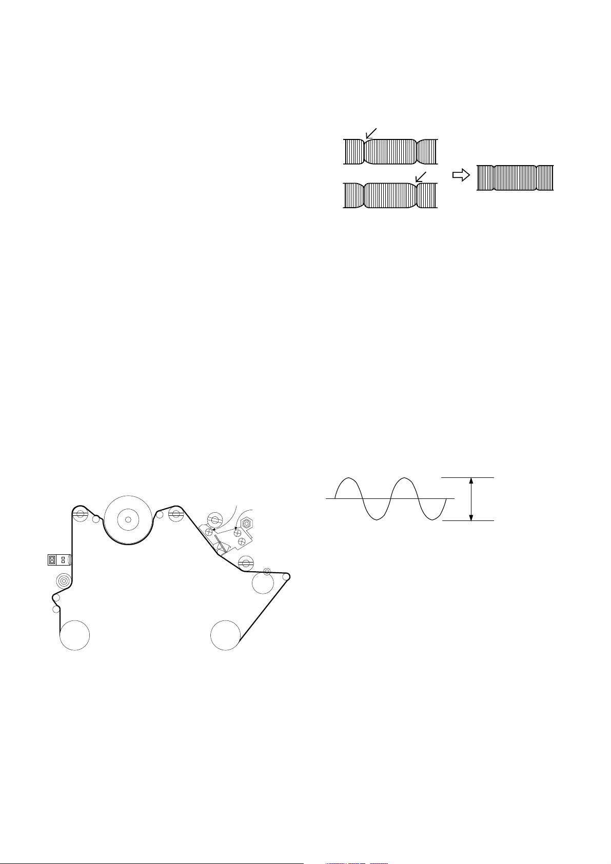
<Adjustment waveform>
1-4. X-Distance Adjustment
1)Turn the Cone Screw of the DECK left or right so that the
RF waveform is maximum.
2)Check if the RF waveform satisfies the linearity by
pressing TRK UP(+) and DOWN(-) button one step.
CAUTION:If the RF waveform becomes maximum with
the Cone Screw more than 2 turns, its out of adjustment.
(2 turns; 720)
1-5. Audio Level Check and Adjustment
1)Connect "+" terminal of RMS Meter (Audio Level Meter)
to J233 on MAIN PCB AUDIO OUT and "-" terminal to
GND, respectively.
2)Play the 1khz and 7khz segments on the alignment tape
and confirm if the spec is meet in item #3. If not adjust
the azimuth screw to meet this spec.
3)Audio Level Spec: 1KHz ; 0.5
6KHz ; 1K
+_0.1Vrms
+_1.5dB
FE HEAD
P1
P0
ARM
TENSION
SUPPLY
REEL
P2
DRUM
P3
X-DISTANCE
ADJUST SCREW
A/C
HEAD
AZIMUTH
SCREW
TAKE-UP
REEL
PINCH
ROLLER
CONE POINT
SCREW
A/C HEAD
HEIGHT ADJUST NUT
P4
<Adjust Parts Location>
1-3. RF linearity check and adjustment
1)Adjust P2 & P3 so that the RF ENVELOPE waveform is
maximum and stabilized .
2)Check if the ENVELOPE waveform is at its maximum size
by pressing TRK UP(+) and DOWN(-) button one step.
CAPSTAN
TAPE
<Adjustment Waveform>
2. CIRCUIT ADJUSTMENT
T/UP
ARM
1. PG Adjustment
1-1. Necessary Instruments
1)Alignment tape SP
2)Oscilloscope
3)10 : 1 Probe
1-2.Adjustment
1)PLAY exclusive use of SP tape. (2HD: NORMAL TAPE)
2)Connect CH 1 of the Oscilloscope to J439 (H/SW) on the
MAIN PCB and VOL/DIV to 1V Range and Trigger the
Oscilloscope.
3)Connect CH 2 of the oscilloscope to J454 (Video Out) on
the main PCB and set the VOL/DIV to 500mV Range.
4)Set TIME/DIV of oscilloscope to 50
5) Adjust VR01 so that V-sync Falling Edge of Video signal
become 412
usec+_20usec.
Adjust waveform
us Range.
3-5
Page 20

Adjust Period
<Adjust Waveform>
* CAUTION:Set the trigger mode of Oscilloscope to DC.
2. Normal REC Bias Level Adjustment
2-1. Necessary Instruments
1) Blank tape for Recording
2)RMS Meter
2-2. Adjustment
1) Set the TV/VCR to A/V input mode.
2)Insert a tape and press REC button.
3)Connect RMS Meter's (+), (-) to R401 on MAIN PCB.
4)Adjust VR401 so that the RMS Meter's indicator become
within 2.6mV
+_0.05mV.
3. Focus Voltage Adjustment
1)Receive the cross hatch pattern.
2)Press the PICTURE button to set the Standard ON
condition.
3)Adjust Focus control knob so that the focus of center &
circumference to be best.
4. Screen Adjustment
1)Press TV/AV button and select AV mode.
2)Adjust SCREEN control until the retrace line is visible and
return until the retrace line is invisible.
*HHHHoooowwww ttttoooo ggggeeeetttt iiiinnnnttttoooo SSSSVVVVCCCC mmmmooooddddeeee wwwwhhhheeeennnn yyyyoooouuuu ddddoooonnnn''''tttt hhhhaaaavvvveeee SSSSVVVVCC
RRRReeeemmmmooootttteeee CCCCoooonnnnttttrrrroooolllllllleeeerrrr..
PPPPuuuusssshhhh tttthhhheeee """"OOOOKKKK"""" KKKKeeeeyyyy oooonnnn tttthhhheeee uuuusssseeeerrrr''''ssss RRRReeeemmmmooootttteeee CCCCoooonnnnttttrrrroooolllllllleeeerrrr aaaannnndddd llllooooccccaaaall
""""OOOOKKKK"""" bbbbuuuuttttttttoooonnnn aaaatttt tttthhhheeee ssssaaaammmmeeee ttttiiiimmmmeeee..
..
..
5. VCO Adjustment
1)Select channel 0.
2) Input PAL Digital pattern (175.25MHz).
3)Press SVC Key on the Service Remote Controller to get
into SVC mode and press PR +/- Key to select VCO.
4)Press VOL +/- Key until OK is displayed on the screen.
7. RF AGC Adjustment
1)Input PAL DIGITAL PATTERN.
2)Connect DMM to AGC(J232) test point on the Main PCB.
3)Press SVC Key on the Service Remote Controller to get
into SVC mode and press PR +/- Key to select AGC.
4) Press VOL +/- Key until DMM reads the data on the table
below.
MODEL
2 TUNER
1 TUNER
NNNNooootttteeee ::::When adjusting 2 TUNER Model, select BOOSTER OFF
Electric fields strength
AGC Voltage
Electric fields strength
AGC Voltage
from MENU.
KL/KB/KI
70dBu 1dBu
5.5 0.1Vdc
65dBu 1dBu
5.6 0.1Vdc
8. White Balance Adjustment
1)Input a signal which lower half is black and upper half is
white.
2) Set the picture at standard on.
3)Press SVC Key on the Service Remote Controller to get
into Service mode.
4)Press PR +/- Key to select BG, RG.
Press VOL +/- Key until X=281
*GG is fixed data at 32 so, do not adjust GG data.
+_3, Y=288+_3.
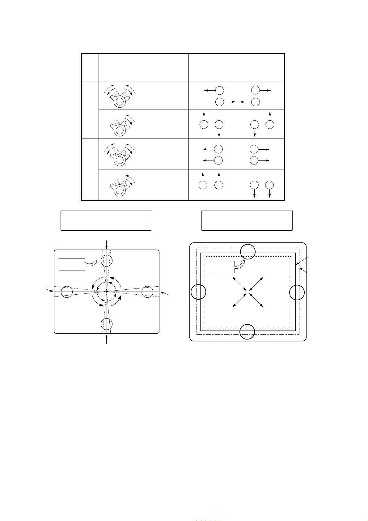
9. Deflection Data Adjustment
1)Input PAL Digital Pattern.
2)Press SVC Key on the Service Remote Controller and
select LINE SERVICE 2 mode.
3)Press PR +/- Key to select an adjustment mode.
4) Press VOL +/- Key to adjust data.
5) Vertical SLOPE adjustment
a) Select V-SLP mode with PR +/- Key.
b) Press VOL +/- Key until the horizontal center line of
CC
ll
the large circle coincides with Blanking Line.
6) Vertical amplitude adjustment
a) Select V-AMP mode with PR +/- Key.
b) Press VOL +/- Key until the upper and lower end of the
large circle reach 5 mm inside from the effective area
of CPT.
7) Vertical Shift Adjustment
a) Select V-SFT mode with PR +/- Key.
b) Press VOL +/- Key until the horizontal center coincides
with the vertical sign slot mark of CPT.
6. LCO Adjustment
1)Select channel 99.
2) Input SECAM-L' pattern (55.75MHz).
3)Press SVC Key on the Service Remote Controller to get
into SVC mode and Press PR +/- Key to select LCO.
4)Press VOL +/- Key until OK is displayed on the screen.
3-6
8) Horizontal Shift Adjustment
a) Select H-SFT mode with PR +/- Key.
b) Press VOL +/- Key until the vertical center coincides
with the horizontal sign slot mark of CPT.
9) Vertical S-Correction Adjustment
a) Select S-COL mode with PR +/- Key.
b) Press VOL +/- Key until the grid of Cross Hatch
Pattern is even all over the screen.
Page 21
PURITY & CONVERGENCE ADJUSTMENT
Caution:
Convergence and Purity have been factory aligned. Do not
attempt to tamper with these alignments.
However, the effects of adjacent receiver components, or
replacement of picture tube or deflection yoke may require the
need to readjust purity any convergence.
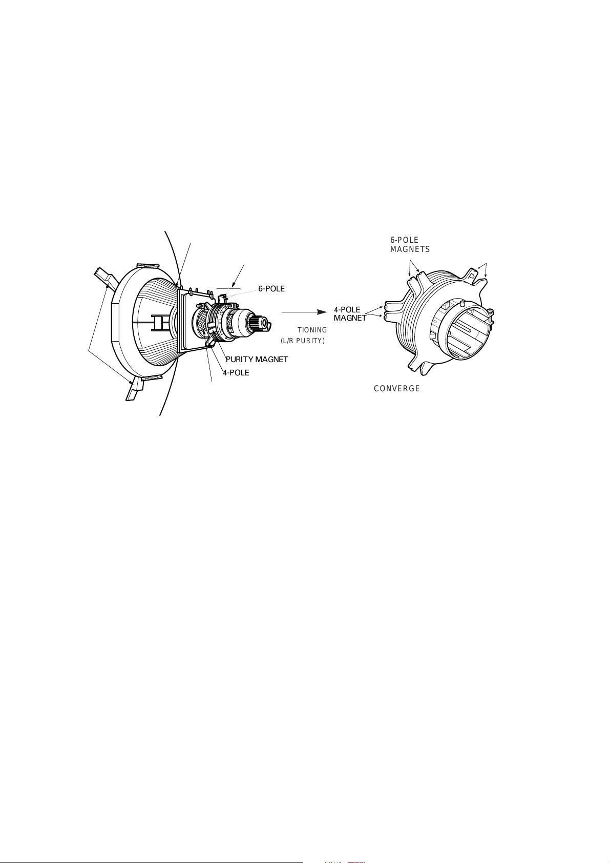
DEFLECTION YOKE
PURITY &CONVERGENCE
MAGNET ASSEMBLY
6-POLE
,,,
RUBBER
WEDGES
,,
,,
,,,
PURITY MAGNET
4-POLE
GLASS CLOTH TAPE
X-AXIS YOKE
POSITIONING
(L/R PURITY)
5.Reconnect the internal degaussing coil.
6. Position the beam bender locking rings at the 9 o'clock
position and the other three pairs of tabs (2,4 and 6 pole
magnets) at the 12 o'clock position.
6-POLE
6-POLE
MAGNETS
4-POLE
MAGNET
MAGNES
CONVERGENCE MAGNET ASSEMBLY
CONVERGENCE MAGNET ASSEMBLY
PURITY MAGNET(2-POLE)
* Purity Adjustment
This procedure DOES NOT apply to bonded yoke and picture
tube assemblies.
The instrument should be at room temperature (60 degrees F or
above) for six (6) hours and be operating at low beam current
(dark background) for approximately 20 to 30 minutes before
performing purity adjustments.
CAUTION:Do not remove any trim magnets that may be
attached to the bell of the picture tube.
1. Remove the AC power and disconnect the internal
degaussing coil.
2. Remove the yoke from the neck of the picture tube.
3. If the yoke has the tape version beam bender, remove it and
replace it with a adjustable type beam bender (follow the
instructions provided with the new beam bender)
4. Replace the yoke on the picture tube neck, temporarily
remove the three (3) rubber wedges from the bell of the
picture tube and then slide the yoke completely forward.
7. Perform the following steps, in the order given, to prepare the
receiver for the purity adjustment procedure.
a. Face the receiver in the "magnetic north" direction.
b. Externally degauss the receiver screen with the television
power turned off.
c. Turn the television on for approximately 10 seconds to
perform internal degaussing and then turn the TV off.
d. Unplug the internal degaussing coil. This allows the
thermistor to cool down while you are performing the purity
adjustment. DO NOT MOVE THE RECEIVER FROM ITS
"MAGNETIC NORTH" POSITION.
e. Turn the receiver on and obtain a red raster by increasing
the red bias control (CW) and decreasing the bias controls
for the remaining two colors (CCW).
f. Attach two round magnets on the picture tube screen at 3
o'clock and 9 o'clock positions, approximately one (1) inch
from the edge of the mask (use double-sided tape).
3-2
Page 22

1.ADJUST YOKE Z-AXIS FIRST
TO GET EQUAL BLUE
COLOR CIRCLES
MAGNETS
RED RED
2 .ADJUST BEAM BENDER 2 POLE
MAGNET TO GET FOUR EQUAL
COLOR CIRCLES
8. Referring to above, perform the following two steps:
a. Adjust the yoke Z-axis to obtain equal blue circles.
b. Adjust the appropriate beam bender tabs to obtain correct
purity (four equal circles).
9. After correct purity is set, tighten the yoke clamp screw and
remove the two screen magnets.
10.Remove the AC power and rotate the receiver 180 degrees
(facing "magnetic south").
11. Reconnect the internal degaussing coil.
12. Turn the receiver on for 10 seconds (make sure the receiver
came on) to perform internal degaussing, and then turn the
receiver off.
13. Unplug the internal degaussing coil.
14. Turn on the receiver and check the purity by holding one (1)
round magnet at the 3 o'clock and a second round magnet at
9 o'clock position. If purity is not satisfactory, repeat steps 8
through 14.
15. Turn off the receiver and reconnect the internal degaussing
coil.
* Convergence Adjustment
Caution:This procedure DOES NOT apply to bonded yoke and
picture tube assemblies.
Do not use screen magnets during this adjustment
procedure. Use of screen magnets will cause an
incorrect display.
1. Remove AC power and disconnect the internal degaussing
coil.
2. Apply AC Power and set the brightness to the Picture Reset
condition. Set the Color control to minimum.
3. Apply 8V to the pin.
6. Reconnect the internal degaussing coil and apply AC power.
7. Turn the receiver on for 10 seconds to perform internal
degaussing and then turn the receiver off again.
8. Unplug the internal degaussing-coil.
9. Turn on the receiver, connect a signal generator to the VHF
antenna terminal and apply a crosshatch signal.
Caution:During the convergence adjustment procedure, be
very careful not to disturb the purity adjustment tabs
are accidentally move, purity should be confirmed
before proceeding with the convergence adjustments.
Note:
Make sure the focus is set correctly on this instrument
before proceeding with the following adjustment.
10. Converge the red and blue vertical lines to the green vertical
line at the center of the screen by performing the following
steps (below TABLE).
a. Carefully rotate both tabs of the 4-pole ring magnet
simultaneously in opposite directions from the 12 o'clock
position to converge the red and blue vertical lines.
b. Carefully rotate both tabs of the 6-pole ring magnet
simultaneously in opposite directions form the 12 o'clock
position to converge the red and blue (now purple)
vertical lines with the green vertical line.
11. Converge the red and blue horizontal with the green line at
the center of the screen by performing the following steps.
(below TABLE)
a. Carefully rotate both tabs of the 4-pole ring magnet
simultaneously in the same direction (keep the spacing
between the two tabs the same) to converge the red and
blue horizontal lines.
b. Carefully rotate both tabs of the 6-pole ring magnet
simultaneously in same direction (keep the spacing
between the two tabs the same) to converge the red and
blue (now purple) horizontal lines with the green
horizontal line.
c. Secure the tabs previsouly adjusted by locking them in
place with the locking tabs on the beam bender.
4. Adjust the Red, Green and Blue Bias controls to get a dim
white line.
5. Remove the AC power and 8V from the pin.
3-3
Page 23
3-4
RING
PAIRS
4
POLE
ROTATION DIRECTION
OF BOTH TABS
OPPOSITE
SAME
OPPOSITE
SAME
MOVEMENT OF RED
AND BLUE BEAMS
B B
RR
OR
OR
B R B R
OR
B
R
B
R
B R
OR
B
R
6
POLE
12. While watching the 6 o'clock positions on the screen, rock the
front of the yoke in a vertical (up/down) direction to converge
the red and blue vertical lines. (Fig upper left)
13. Temporarily place a rubber wedge at the 12 o'clock position
to hold the vertical position or the yoke.
14.
Check the 3 o'clock and 9 o'clock areas to confirm that the red
and blue horizontal lines are converged.
If the lines are not converged, slightly offset the vertical tilt of the
yoke (move the rubber wedge if necessary) to equally balance the
convergence error of the horizontal lines at 3 o'clock and 9 o'clock
and the vertical lines at 6 o'clock and 12 o'clock.
15. Place a 1.5 inch piece of glass tape over the rubber foot at
the rear of the 12 o'clock wedge.
16. While watching the 6 o'clock and 12 o'clock areas of the
screen, rock the front of the yoke in the horizontal (left to
right) motion to converge the red and blue horizontal lines.
(Fig. upper right)
17. Temporarily place a rubber wedge at the 5 o'clock and 7
o'clock positions to hold the horizontal position of the yoke.
18. Check the 3 o'clock and 9 o'clock areas to confirm that the
red and blue vertical lines are converged. If the lines are not
converged, slightly offset the horizontal tilt of the yoke (move
the temporary rubber wedges if necessary) to equally
balance the convergence error of the horizontal lines at 6
o'clock and 12 o'clock and the vertical lines at 3 o'clock and 9
o'clock.
19. Using a round magnet confirm purity at the center, right and
left sides and corners. See Purity Adjustment Procedure.
20. Reconfirm convergence and apply a 1.5 inch piece of glass
tape over the rubber foot at the rear of the 5 o'clock and the 7
o'clock wedges.
RED
BLUE
RED BLUE
BLUE
RED
GREEN
GREEN
BLUE RED
GREEN
GREEN
ADJUSTMENT
VIEWING
AREA
UP/DOWN ROCKING OF THE YOKE
CAUSES OPPOSITE ROTATION OF RED
AND BLUE RASTERS
ADJUSTMENT
VIEWING
AREA
RED
RED
GREEN
TV
SCREEN
LEET/RIGHT ROCKING OF THE YOKE
CAUSES OPPOSITE SIZE CHANGE OF
THE RED AND BLUE RASTERS
UP/DOWN ROCKING OF THE YOKE
CAUSES OPPOSITE ROTATION OF RED
AND BLUE RASTERS
LEFT/RIGHT ROCKING OF THE YOKE
CAUSES OPPOSITE SIZE CHANGE OF THE
RED AND BLUE RASTERS
Page 24

4-1
FRONT LOADING MECHANISM DISASSEMBLY
¡¡
‹
Front Loading Mechanism Assembly, Parts Location
¡¡
ÿ
Component list below will be discribed as
if the top and bottom covers, front panel
and deck mechanism assembly have
already been removed.
1. Guide Cassette
2. Bracket Assembly Side (R)
3. Top Plate
4. Holder Assembly Cassette
5. Arm Assembly F/L
6. Plate Reflector
7. Opener Door
8. Plate Ground(R)
9. Plate Ground(L)
6. Plate Reflector
3. Top Plate
8. Plate Ground (R)
9. Plate Ground (L)
6. Plate
Reflector
1. Guide Cassette
4. Holder
Assembly
Cassette
2. Bracket Assembly
Side(R)
7. Opener Door
5. Arm Assembly F/L
Page 25

FRONT LOADING MECHANISM DISASSEMBLY
1.Front Loading Mechanism Assembly
(Fig. A-1)
1)Remove the Top and Bottom Covers and Front Panel.
2) Remove two screws(A).
3)Lift up the Front Loading Mechanism Assembly in the
direction of arrow(B).
NOTE
When disassembling and reassembling:
a.Give special attention to removal and to reassembly
because two tabs(L), (R) are engaged.
(A)
(B)
(L)
(R)
Fig. A-1 Front Loading Mechanism
3. Bracket Assembly Side (R)
1)Push the tabs(L), (R) of Bracket Assembly Side(R) to
disengage with the Top Plate and remove it in the
direction of arrow(A).
Top Plate
(A)
(L)
(Fig. A-3)
Plate Ground
(A)
(R)
Bracket Assembly
Side(R)
Fig. A-3 Bracket Assembly Side(R)
4.Bracket Side(L)/Top Plate (Fig. A-4)
1)Remove the screw(B).
2)Remove the plate Ground(L), in the direction of
arrow(A).
3)Push the locking tab(L1) and then remove the Bracket
Side(L) in the direction of arrow(B).
4)The Top Plate can be removed by Separating the
Bracket Side(L).
2. Guide Cassette (Fig. A-2)
1)Push tab(R) of the Cassette Guide and disengage with
Bracket Side(R) and push tab(L) of the cassette Guide
which is engaged with Bracket Side(L) and remove it in
the direction of arrow (B).
(L)
(B)
Cassette Guide
Fig. A-2 Guide Cassette
(B)
(R)
(B)
(A)
(C)
Brackdt Side(L)
Plate Ground(L)
Hook(L)
(B)
(L1)
Top Plate
Fig. A-4 Bracket Side(L)/Top Plate
4-2
Page 26

FRONT LOADING MECHANISM DISASSEMBLY
5.Holder Assembly Cassette (Fig. A-5)
1)Separate the Bracket Assembly Side(R).
2)Push the two lever tabs(L), (R) down and separate the
Holder Assembly Cassette and the Arm Assembly F/L
from the Top Plate.
Holder
Assembly Cassette
Fig. A-5 Holder Assembly Cassette
6.Arm Assembly F/L (Fig. A-6)
1) Remove by pulling the Arm F/L(R) from the Bracket
Holder(R) Boss in the direction of arrow(A).
2)Separate the Arm Assembly F/L from Cassette Holder
Boss in the direction of arrow(B).
7.Spring Stopper (Fig. A-7)
1)Remove the Spring Stopper which is connected to the
tabs(A), (B) of the Lever Stopper(R) and the Bracket
Holder(R).
Lever Stopper(R)
Spring Stopper
(A)
(B)
Bracket Holder(R)
Fig. A-7
Spring Stopper
8.Plate Reflector (Fig. A-8)
1)Detach the Plate Reflector(L) from the Bracket Side(L)
by using a knife.
2)Detach the Plate Reflector(R) from the Bracket
Assembly Side(R) by using a knife.
NOTE
When disassembling and reassembling:
a. Be sure to remove the Arm F/L(R) first. If not the Arm
Assembly F/L can be damaged.
(B)
(A)
Arm Assembly F/L
Fig. A-6 Arm Assembly F/L
Bracket Side(L)
Bracket
Assembly Side(R)
Plate Reflector
(L), (R)
Fig. A-8 Plate Reflector
4-3
Page 27

DECK MECHANISM DISASSEMBLY
*
‹
Deck Mechanism Parts Location
TOP VIEW
Auto Head Cleaner Assembly
Drum Brush
A/C Head Assembly
Bracket Assembly
L/D Motor
FE Head
Drum Assembly
Base Assembly
P2/P3
Tension Arm
Assembly
Supply Reel
Assembly (S27)
TAB Lever
BOTTOM VIEW
Capstan Motor
Assembly
Holder
Assembly Pinch
Arm Assembly T/up
Gear Pinch Cam
Plate Up
Take-up Reel
Assembly (T27)
Mode Switch
Slider Plate
Gear Pulley
H1 Lever
Gear H2/H1
Clutch Assembly
T27
Bracket Cam
Clutch Assembly
S27
Arm Assembly
Idler
4-4
Page 28

DECK MECHANISM DISASSEMBLY
1.Auto Head Cleaner Assembly (Fig. B-1)
(Optional Item)
1)Push the tab(A) of Auto Head Cleaner and remove the
Cleaner Arm Assembly.
NOTES:
When disassembling and reassembling:
a. Do not allow fingers or tools to touch the outside of the
Drum.
b. Be careful not to get any foreign substance on the
Roller.
Cleaner Arm Assembly
(A)
Drum
Assembly
Drum
Base
(A)
7(A)
(B)
Fig. B
-2 Drum and Base Assembly
Drum
Brush
(A)
Fig. B
-1 Auto head cleaner Assembly
2.Drum and Base Assembly (Fig. B-2)
1)Remove the Auto Head Cleaner Assembly. (option)
2)Remove three screws(A) and separate the Drum
Assembly, Drum Base and the Drum Brush from the
Deck Mechanism Assembly.
3) Remove three screws(B) on the back side and remove
the Drum Assembly from the Drum Base.
NOTES:
When disassembling and reassembling:
a. Do not touch the video tips with fingers or tools.
Give special attention to disassembling and
reassembling of Auto Head Cleaner Assembly.
b. After assembling, adjust the tape transport system and
Servo PG.
3.Drum Sub Assembly and Motor
Assembly (Fig. B-3-1)
1)Remove the Drum Base from the Deck Mechanism
Assembly.
2)Separate the Drum Assembly from the Drum Base.
3)Remove two screws(A) and then remove the rotor.
4)Remove three screws(B) and then remove the stator.
NOTE
When disassembling and reassembling:
a. Do not touch the video tips with fingers or tools.
Drum
Sub Assembly
stator
Motor
Assembly
(B)
rotor
4-5
(A)
Fig. B
-3-1 Drum Sub and Motor Assembly
Page 29

DECK MECHANISM DISASSEMBLY
4.A/C (Audio/Control) Head Assembly
(Fig. B-4)
1)Unplug the A/C connector from the Loading Motor
P.C.B.
2)Remove two screws(A) and remove the A/C Head
Assembly from the Deck Mechanism Assembly.
NOTES:
When disassembling and reassembling:
a. When assembling, the 3mm hole of the Base A/C
should coincide to 3mm hole in the Chassis.
b. Do not touch the A/C Head Tips with fingers or tools.
c. After reinstalling the Audio Control Head Assembly,
adjust the Tilt, Azimuth and Height of A/C Head.
(A)
5.FE (Full Erase) Head Assembly (Fig. B-5)
(Optional Item)
1)Push two tabs(A) and remove the FE Head.
NOTE
When disassembling and reassembling:
a. Be careful not to get any foreign substance on the FE
Head.
(A)
Fig. B-4 A/C Head Assembly
Fig. B-5 FE Head Assembly
4-6
Page 30

DECK MECHANISM DISASSEMBLY
6.Plate Up/Supply Main Brake/T ake up Main
Brake/Body Prism Led Assembly (Fig. B-6)
1)Plate Up
a. Remove three screws(A) and remove the Plate Up.
2)Supply Main Brake
a. Remove the Spring MB.
b. Lift up the Supply Main Brake.
3)Take-Up Main Brake
a. Lift up the Take-Up Main Brake.
4)Body Prism Led
a. Remove the Body Prism Led.
SMB
(A)
Body
Prism Led
(A)
Plate Up
(A)
TMB
Spring
MB
NOTES:
When disassembling and reassembling:
a. (D) is engaged to the cam groove of the Gear Cam L/D
and two tabs(C) are engaged in the chassis. (care must
be taken not to damage the two tabs when
disassembling and reassembling)
b. When disassembling, turn to the counterclockwise and
lift up so that grease which may be on (D) is not
transfered to the Reel Brake Drum.
c. When assembling, the 2.5mm hole of the Lever
Assembly Tension should be aligned with the 2.5mm
hole in the chassis.
d. After reassembling, adjust the Tension.
Spring Tension
Tension Arm
Tension shaft
(C)
(B)
(C)
(D)
Holder Band (A)
Holder Band (C)
Holder Band (B)
Lever Ass'y Tension
Fig. B-6 Plate up/SMB/TMB/BPL
7.Tension Arm/Lever Assembly T ension
(Fig. B-7)
1)Remove the Spring Tension.
2)Push the tab(A) of the Base Tension on the back cover
of the Deck Mechanism Assembly outward and remove
the Tension Arm Assembly.
3)Push the tab(B) on the back side of the Holder Band(A)
and remove the Tension Arm Assembly.
4)Push two tabs(C) on the bottom side of the Lever
Tension and Lift up the Lever Assembly Tension.
Chassis
Hole (2.5mm)
(A)
Fig. B-7 Tension Arm/Lever Assembly Tension
8. TAB Lever (Fig. B-8)
(Optional Item)
1)Remove the Lever Ass'y Tension.
2)Remove the Spring TAB.
3)Push the tab(A) on the bottom side of TAB Lever and
remove the TAB Lever.
Spring TAB
(A)
TAB Lever
4-7
Fig. B-8 TAB Lever
Page 31

DECK MECHANISM DISASSEMBLY
9.Supply Reel/T ake Up Reel Assembly
(Fig. B-9)
1)Lift up Reel(S), (T) after removing the Plate Up and
Band Assembly.
NOTES:
a. Be sure not to interchange the Take-up Reel and the
Supply Reel.
b. Do not allow the Brake Drum to come in contact with
grease.
Supply Reel(S27)
(White)
Take-up Reel(T27)
(Black)
11.Gear H1, H2/Lever H1 (Fig. B-11)
1)Push and lift up the hook(B) of Lever H1.
2)Remove the washer(A) and then lift up the Gear H1.
3)Lift up the Spring H1.
4)Push and lift up the hook(B) of the Gear H2.
(B)
Lever H1
(B)
Gear H2
(C)
Washer(A)
Gear H1
Spring H1
Fig. B-9 Supply Reel/Take-up Reel Assembly
10. Gear Pulley/Belt Capstan (Fig. B-10)
1)Turnover the Deck Mechanism Assembly.
2)Remove the Belt Capstan.
3)Remove the washer(A) and then lift up the Gear Pulley.
Belt Capstan
Washer(A)
Gear Pulley
Fig. B-11 Gear H1,H2/Lever H1
12.Arm Assembly Idler (Fig. B-12)
1)Lift up the Gear Pulley after removing the washer(A).
2)Lift up the Spring Up/D after removing the washer(B).
3)Lift up the Arm Assembly Idler.
Washer(A)
Washer(B)
Spring Up/D
Arm Ass'y Idler
Fig. B-10 Gear Pulle y/Belt Capstan
Fig. B-12 Arm Assembly Idler
4-8
Page 32

DECK MECHANISM DISASSEMBLY
13.Mode S/W (Fig. B-13)
1)Lift up the Lever H1.
2)Remove the screw(A) and lift up the Mode S/W.
NOTE
a. When assembling mode, the groove of Gear ( ) and Body
( o) of the Mode Switch should be aligned.
Lever H1
(A)
Groove (o), ( )
U
U
Mode S/W
15.CAM Bracket Assembly
1)Remove three screws(A).
2)Remove the CAM Bracket Assembly.
(Fig. B-15)
NOTE
a. The (Tension Shaft Holder) fixes the Tension Shaft on Fig
B-7. therefore when the CAM Bracket Assembly is removed,
First remove the Tension Arm on Fig B-7.
(A)
CAM Bracket
(A)
(A)
(Tension shaft Holder)
Fig. B-15 CAM Bracket Assembly
Fig. B-13 Mode S/W
14.Capstan Motor Assembly (Fig. B-14)
1)Remove three Screws(A) on the top side and remove
the Capstan Motor Assembly.
Capstan Motor
(A)
(A)
(A)
Fig. B-14 Capstan Motor Assembly
16. Cam Bracket/Lever Jog/Gear Jog (Fig. B-16)
(Optional Item)
1)Remove the Cam Bracket Assembly.
2)Remove the Spring Jog.
3)Push the tab(A) and remove the Lever Jog.
4)Push the tab(B) and remove the Gear Jog.
NOTE
a. The tab(B) on the Gear Jog should be in groove of the
Lever Jog.
CAM Bracket
(A)
Gear Jog
(B)
Fig. B-16 Cam Bracket/Lever Jog/Gear Jog
Lever Jog
Spring Jog
4-9
Page 33

DECK MECHANISM DISASSEMBLY
17.Gear Cam L/D (Fig. B-17)
1)Remove the Cam Bracket Assembly.
2)Remove the Gear Cam L/D.
NOTE
1)When assembling the Gear Cam L/D, the groove
( ) of Plate Slider should coincide with to the groove
( ) on the Gear Cam L/D.
CAM Bracket
Gear CAML/D
19.Gear Assembly P2/P3 (Fig. B-19)
1)Remove the Plate Slider.
2)Remove by pushing one hook(B) on the top side of Gear
Assembly P3.
3)Remove by pushing one hook(A) on the top side of Gear
Assembly P2.
NOTES:
When disassembling and reassembling:
a. The P2 and P3 Gear Assembly should not be
interchanged.
b. The groove( ) of Gear P2 should be aligned to
the groove( ) of Gear P3.
c. Set the hole of Lever to the Boss of P2 and P3 Base
Assembly.
(When assembling make sure that the Lever is not
bent.)
GEAR P3
GEAR P2
Fig. B-17 Gear Cam L/D
18.Gear PS/Plate Slider
1)Remove two washers(C).
2)Remove the Plate Slider.
3)Remove the Gear PS.
(Fig. B-18)
NOTE
1)When the hole(A) of the Gear PS is aligned to the
hole(B) of the chassis, the groove( ) of the Plate Slider
should be aligned to the groove( ) of the Gear PS.
(C)
(C)
(A)
Gear PS
Plate Slider
(A)
Lever
BOSS
BOSS
Fig. B-19 Gear Assembly P2/P3
20.Base Assembly P2/P3 (Fig. B-20)
1)Remove the P2/P3 Gear Assembly.
2)Remove the P2/P3 Base Assembly.
BASE P2
(B)
BASE P3
(B)
Fig. B-18 Gear PS/Plate Slider
Fig. B-20 Base Assembly P2/P3
4-10
Page 34

DECK MECHANISM DISASSEMBLY
21.Guide Roller Assembly (Fig. B-21)
1)Remove two screws(A).
2)Remove the Guide Roller From the Base P2/P3 by
turningit.
NOTE
When disassembling and reassembling:
a. The P2 and P3 Base should not be interchanged.
Guide Roller
(A)
BASE P2
Guide Roller
(A)
BASE P3
23.Clutch Assembly T27 (Fig. B-23)
1)Remove the Gear H1 and Arm Assembly Idler.
2)Remove the washer(A).
3)Remove the Clutch Assembly T27.
Washer (A)
Clutch T27
Fig. B-23 Clutch Assembly T27
Fig. B-21
Guide Roller Assembly
22.Clutch Assembly S27 (Fig. B-22)
1)Remove the Gear Cam L/D and the Arm Assembly Idler.
2)Remove the washer(A).
3)Remove the Clutch Assembly S27.
Washer (A)
Clutch S27
24.Lever F/R & Arm F/R (Fig. B-24)
1)Remove the Plate Slider.
2)Remove the washer(A).
3)Remove the Lever F/R.
4)Remove the Arm Assembly Idler.
5)Remove the Arm F/R.
NOTE
1)When disassembling the Arm F/R should be horizontal.
Washer (A)
Lever F/R
ARM F/R
4-11
Fig. B-22
Clutch Assembly S27
Fig. B-24
Lever F/R&Arm F/R
Page 35

DECK MECHANISM DISASSEMBLY
25.Holder Pinch Assembly (Fig. B-25)
1)Separate the Holder Pinch Assembly by pushing tab(A)
on the L/D Motor Bracket in the direction of arrow (B).
Holder Pinch
B
(A)
27.L/D Motor Bracket Assembly (Fig. B-27)
1)Remove three Screws(A).
2)Push the tabs(A) and remove the L/D Motor Bracket
Assembly.
NOTES:
When assembling and disassembling:
a. Make sure Grease from the Gear Pinch does not come in
contact with the wing of the L/D Motor Bracket.
(A)
Chassis
L/D Motor
Bracket
(A)
(A)
(A)
Fig. B-25
Holder Pinch Assembly
26.Pinch Arm Assembly (Fig. B-26)
1)Remove the Spring Pinch.
2)Remove the Pinch Arm Assembly by turning it
counterclockwise.
Spring Pinch
Pinch Arm
Pinch Roller
Fig. B-27 L/D Motor Bracket Assembly
28.Worm Wheel (Fig. B-28)
1)Remove the L/D Motor Bracket Assembly.
2)Push two Tabs(A) on the L/D Motor Bracket and then
remove it.
Worm Wheel
(A)
Fig. B-26
Pinch Arm Assembly
Fig. B-28
Worm Wheel
4-12
Page 36

29. L/D Motor Assembly & Worm L/D Motor &
L/D Motor Bracket (Fig. B-29)
1) Remove the L/D Motor Bracket Assembly.
2) Push the L/D Motor Assembly in lower direction and
then remove.
3) Remove the Worm L/D Motor from the L/D Motor
Assembly in the direction of arrow (A).
4) Remove the L/D Motor Assembly and the Worm L/D
Motor and then L/D Motor Bracket is removed.
30 . Gear CNT (Fig. B-30)
1) Remove the L/D Motor Bracket Assembly.
2) Remove the Pinch Arm Assembly.
3) Remove the Gear CNT.
31. Gear Pinch (Fig. B-31)
1) Remove the Pinch Arm Assembly.
2) Remove the Gear CNT.
3) Remove the Gear Pinch.
4) When reassembling, make sure that the two teeth, Gear
pinch CAM(£ ) and Gear pinch(£ ), with timing marks
line up with the arrow at two o'clock on the Pinch Cam
Gear. (See Fig on B-30)
32. T/Up Arm Assembly (Fig. B-32)
1) Remove the L/D Motor Bracket Assembly.
2) Turn over the T/Up spring and separate the T/Up Arm
Assembly.
3) Remove the spring.
4-13
Fig. B
-29
L/D Motor Assembly/ Worm
L/D Motor/ L/D Motor Bracket
Gear CNT
Gear Pinch CAM
Gear Pinch
A
B
Fig. B-30
Gear CNT
Fig. B-31
Gear Pinch
L/D Motor Ass'y
L/D Motor
Bracket
(A)
Worm L/D Motor
Gear Pinch
Gear Pinch CAM
DECK MECHANISM DISASSEMBLY
T/Up Arm
T/Up Spring
Fig. B-32
T/up Arm Assembly
Page 37

DECK MECHANISM DISASSEMBLY
33.Gear Pinch Cam (Fig. B-33)
1)Remove the T/Up Arm Assembly.
2)Remove by pushing one tab(A) on the bottom side of the
Gear Pinch Cam.
NOTE
When disassembling and reassembling:
a. The small hole on the Gear Pinch Cam and hole of
chassis should be aligned.
Gear Pinch CAM
(A)
Fig. B-33
Gear Pinch Cam
4-14
Page 38

MECHANISM ADJUSTMENT
¡¡
‹
Tools and Fixtures for Deck
1. Cassette Torque meter
Parts No: D00-D006
300
S
-
T
250
H
V
-
200
K
R
150
S
SRK
VIDEO
CASSETTE
H
V
T
-
-
K
T
R
0
S
TORQUE
50
0
METER
VHT-303
50
100
150
200
250
300
4. Torque gauge adaptor
Parts No: D09-R001
2. Alignment tape
Parts No NTSC: DTN-0001
PAL: DTN-0002
5. Post height adjusting driver
Parts No: DTL-0005
3. Torque gauge
Parts No: D00-D002
6. + Type driver (¿5)
Obtain locally
4-15
Page 39

MECHANISM ADJUSTMENT
1. Mechanism and Mode Switch Alignment Check
Purpose:To determine if the mode switch and mechanism are in the correct position, when a
tape is ejected from the loading mechanism.
Test Equipment /Fixture Test Conditions VCR (VCP) State Check Point
*
Eject Mode (with cassette ejected)
*
Blank tape
1)Turn power on and eject the cassette by pressing the
eject button.
2)Remove the top and bottom covers.
3)Visually check the alignment of the Pinch Cam gear
and PS gear holes, line up with holes in the chassis
(figure C-2).
4)If the gears in step 3 do not align as indicated, then
rotate the shaft of the loading motor to either the
clockwise or counterclockwise direction until alignment
does occur.
CHECK DIAGRAM
*
Mechanism and Mode Switch Position
5)Turn the unit over and remove the main P.C.B thus
exposing the bottom side of the deck mechanism.
6)Check the alignment of the mode switch as illustrated
in figure C-1, (A).
7)If the alignment is incorrect then remove the mode
switch and align as shown in figure C-1 with out
changing the position of the Pinch Cam gear and PS
gear.
8)Remount the mode switch and main P.C.B assembly
and check operation.
Mode S/W
(A)
BOTTOM VIEW
TOP VIEW
Gear ( ) and Body (¡Û) groove alignment
Fig. C-1
Gear
Pinch Cam
Hole
Gear
PS
Hole
Fig. C-2
4-16
Page 40

MECHANISM ADJUSTMENT
2.Preparation for Adjustment (T o set VCR
(VCP) to the loading state without inserting
a cassette.)
1)Unplug the Power Cord from the AC outlet.
2)Separate the Top Cover and Front Loading Mechanism.
3)Plug the Power Cord into the AC outlet.
4)Turn the VCR on and push the tact switch in the P.C.B.
Assembly.
The VCR can accept inputs for each mode in this case.
However the rewind and review operation cannot be
performed for more than a few seconds because the
take-up reel table is in the stop state and reel pulses
cannot be detected.
NOTES:
Always return the VCR(VCP) to the Front Loading Mechanism Assembly State in the following order after the above
operations have been performed.
1)Press the Eject button after turning the power ON.
2)Wait for about 10 seconds until searching out the
assembly position.
3)Assemble the Front Loading Mechanism and connect
the Front Loading Mechanism Connector.
4)Refer to the "Front Loading Mechanism Disassembly"
Section.
NOTE
Cover the holes in the end sensors with black tape to
prevent a light leak.
3.Tension Post Position and Tension Adjustment
Purpose:To insure uniform tape contact with the video head by maintaining constant tape
tension.
Test Equipment /Fixture
*
Cassette Torque Meter
(For play 100g/cm)
Test Conditions VCR(VCP) State
*
Position Adjustment: Play without a
cassette
*
Tension Check: Play
Adjustment Point
*
Holder Band B and C
Position Adjustment
1)Remove cassette.
2)Adjust the position of tension post in accordance
with figure C-3.
NOTE
Align the Tension Post (2mm) to the hole in the Chassis
(2.5mm).
Post P1
Tension Arm
Chassis Hole (2.5mm)
¡¡
Tolerance
æ
0.3mm with in
Post Tension
Post P0
Tension Adjustment
1)Turn on VCR and load the cassette torque meter.
2)Press the play button and observe the torque tension
on the supply reel (spec. 37g/cm+5g/cm).
3)If torque is out of spec. then use a Phillips screw
driver and move the screw head located in the center
of the B and C band hold; to either the right or left
until correct torque is indicated.
Lever Tension
Hold Band(B)
Hold Band(C)
4-17
Fig. C
-3
Page 41

MECHANISM ADJUSTMENT
4. Checking Torque
Purpose:To insure smooth transport of the tape during each mode of operation. If tape
transport is abnormal, then check the torque as indicated by the chart below .
Test Equipment /Fixture
*
Torque Gauge(600 g/cm ATG)
*
Torque Gauge Adaptor
*
Cassette Torque Meter
VNTSC: 16.67msec
PAL: 20msec
Item
Slack Removal Torque
Fast Forward Torque
Rewind Torque
Play Take-Up Torque
Review Torque
Mode
Unloading
Fast Forward
Rewind
Play
Review
Cassette Torque Meter
Cassette Torque Gauge
Cassette Torque Gauge
Cassette Torque Meter
Cassette Torque Meter
Checking Method:
The Values are measured by using a torque gauge and
torque gauge adaptor with the torque gauge affixed.
NOTE
The torque reading to measure occurs when the tape
abruptly changes direction from fast forward or rewind
mode, when quick braking is applied to both reels.
*
Set the VCR to each operating mode without
Test Equipment
Test Conditions VCR(VCP) State
inserting a cassette. (See '2. Preparation for
Adjustment'. Page 4-17)
Measurement Reel
Supply Reel
Take-Up Reel
Supply Reel
Take-Up Reel
Supply Reel
Measurement Values
More than 150~270g/cm
More than 500g/cm
More than 500g/cm
55~95g/cm
170~250g/cm
Torque Gauge
T
H
V
-
K
R
S
300
S
-
250
50
0
Fig. C-5
200
150
VHT-303
SRK
VIDEO
CASSETTE
TORQUE
METER
Torque Gauge
Adaptor
H
V
T
-
-
K
T
R
0
S
50
100
150
200
250
300
Reel Table
Fig. C-4
4-18
Page 42

MECHANISM ADJUSTMENT
5. Guide Roller Height Adjustment
Purpose:To regulate the height of the tape so that the bottom of the tape runs along the
tape guide line on the lower drum.
A. Preliminary Adjustment
Test Equipment /Fixture
*
Post Height Adjusting Driver
*
Hexagonal Wrench or Allen
Wrench Phillips screw driver
Test Conditions VCR(VCP) State
*
Allows a good tape to play
normally in spite of a damaged
guide roller.
Adjustment Procedure
1)Perform the precise adjustment(See below B).
2)If the Guide Roller is damaged, loosen the Guide Roller
retaining screw and replace the Guide Roller.
3)Adjust the height of P2, P3 so that TAPE is adjacent to
the guide line.
B. Precise Adjustment
Test Equipment /Fixture
*
Oscilloscope
*
Alignment Tape
*
Post Height Adjusting
Driver
Test Equipment Connection Points
*
CH-1: PB RF Envelope
*
CH-2: NTSC: SW 30Hz
*
*
PAL : SW 25Hz
Head Switching Output
Point
RF Envelope Output
Point
*
Guide Roller Height Adjustment
screws on the Supply and Take-Up
Guide Rollers.
ADJUSTMENT DIAGRAM
Fig. C-5-1
Test Conditions VCR(VCP) State
*
Play an alignment tape
Waveform Diagrams
P2 POST
ADJUSTMENT
Adjustment Point
GUIDE ROLLER HEIGHT
ADJUSTMENT SCREW
UPPER FLANGE
GUIDE ROLLER
RETAINING SCREW
Adjustment Point
*
Guide Roller Height
Adjustment Screws.
Adjustment Procedure
1)Play an alignment tape after connecting the probe of
the oscilloscope to the RF Envelope Output Test Point
and Head Switching Output Test Point.
2)Tracking Control (in PB mode): Center position (When
this adjustment is performed after the drum assembly
has been replaced, set the tracking control so that the
RF output is maximum.)
3)Height adjustment screw: Flatten the RF waveform.
(Fig. C-5-2)
4)Turn (Move) the tracking control (in the Playback
mode) clockwise and counterclockwise. (Fig. C-5-3))
5)Check that any drop of RF output is uniform at the start
and end of the waveform.
CAUTION
If the adjustment is excessive or insufficient the tape will
jam or fold.
4-19
P3 POST
ADJUSTMENT
Fig. C-5-2
Tracking control at center
Fig. C-5-3
Connection Diagram
RF ENVELOPE OUTPUT TEST POINT
HEAD SWITCHING OUTPUT TEST
POINT
Turn the Roller Guide Height
Adjustment Screw slightly
to flatten the waveform.
Turn (Move) the tracking
control to both directions.
OSCILLOSCOPE
CH-1 CH-2
Page 43

MECHANISM ADJUSTMENT
6. Audio/Control (A/C) Head Adjustment
Purpose:To insure that the tape passes accurately over the audio and control tracks in
exact alignment in both the record and playback modes.
A.Preliminary Adjustment (Height and tilt adjustment)
Perform the Preliminary adjustment, when there is no Audio Output signal with a blank tape.
Test Equipment /Fixture
*
Blank Tape
*
Screw Driver(+) Type 5mm
Test Conditions VCR(VCP) State
*
Play the blank tape (CTL Tape)
Adjustment Procedure /Diagrams
1)Initially adjust the A/C head assembly as shown in
figure C-6-1, by using the height adjustment screw(B).
2)Play a blank tape and observe if the tape passes
accurately over the A/C head without tape curling or
folding.
3)If folding or curling does occur then adjust the Tilt
adjusting screw(C) while the tape is running to
resemble figure C-6-3.
4)Confirm that the tape passes over the A/C head
assembly as indicated by proper audio reproduction
and proper tape counter performance.
NOTE
Ideal A/C head height occurs, when the tape runs
between 0.2~0.25mm above the bottom edge of the A/C
head core.
Adjustment Points
*
Tilt Adjustment Screw(C)
*
Height Adjustment Screw(B)
*
Azimuth Adjustment Screw(A)
¡¡
æ
11.1
0.05mm
Tilt
Adjustment
Screw(C)
Height Adjustment
Screw(B)
Fig. C-6-1 A/C Head Base
X value
Adjustment
Screw(X)
Azimuth Adjustment
Screw(A)
Turning
Center
Fix
Fig. C-6-2 A/C Head Assembly
A/C Head
Tape
P4
Tape
0.2~0.25 mm
Fig. C-6-3
4-20
Page 44

MECHANISM ADJUSTMENT
B. Confirm that the tape passes smoothly between
the T/UP guide and the Pinch Roller (Using a
mirror or the naked eye).
1)After completing step A. (Preliminary Adjustment), check
that the tape passes around the T/UP post without folding
at the top or bottom.
If folding is observed, due the following:
a. If folding is observed at the lower part of the T/UP
post, then slowly turn the tilt adjustment in the
clockwise direction to eliminate tape the curling.
b. If folding is observed at the upper part of the T/UP
D. Precise Adjustment (Azimuth adjustment)
Test Equipment /Fixture
*
Oscilloscope
*
Alignment tapes
*
Screw Driver(+) Type 5mm
Test Equipment
Connection Point
*
Audio output jack
Adjustment Procedure
1)Connect the probe of oscilloscope to Audio Output Jack.
2)Alternately adjust the Azimuth adjustment screw(A) and
the Tilt adjustment screw(C) for maximum output of the
1KHz and 7KHz segments, while maintaining the flattest
envelope differential between the two frequencies.
post, then slowly turn the tilt adjustment in the
counterclockwise direction to eliminate the tape
curling.
C. RF Fine Adjustment (only if the RF waveform
differs from figure C-5-3).
1)Check the RF Envelope after confirming smooth tape
transport path at the T/UP Guide/Pinch Roller.
Test Conditions
VCR (VCP) State
*
Play an alignment tape
1KHz, 7KHz sections.
1KHZ
A: Maximum
Adjustment Points
*
Azimuth Adjustment Screw(A)
*
Tilt Adjustment Screw(C)
7KHZ
B: Maximum
Fig. C-6-4
7. X-Value Adjustment
Purpose:To obtain compatibility with other VCR(VCP).
Test Equipment /Fixture
*
Oscilloscope
*
Alignment tapes
*
Screw Driver(+) Type 5mm
*
Post Height Adjusting
Driver
Adjustment Procedure
1)Loosen the fixed mounting and X Value adjustment
screw.
2)Allow the mechanism to run long enough for auto
tracking to complete it's cycle.
3)Move the A/C base laterally in the direction as shown
in the diagram to find the center of the peak that
allows for the maximum waveform envelope. This
method should allow the 30um head to be centrally
located over the 60um tape track.
4)Tighten the A/C head assembly mounting screws.
Test Equipment
Connection Point
*
CH-1: PB RF Envelope
*
CH-2: NTSC: SW 30Hz
PAL : SW 25Hz
*
Head Switching Output
Test Point
*
RF Envelope Output Test
Point
*
Adjustment Diagram
Tilt
Adjustment
Screw(C)
Height
Adjustment
Screw(B)
Connection Diagram
Test Conditions
VCR (VCP) State
Play an alignment tape
Left
Right
Fig. C-7
Adjustment diagrams
Groove at the
Base A/C
3mm Hole
X value Adjustment
Screw(X)
Azimuth
Adjustment
Screw(A)
Turning
Center
Fixed
OSCILLOSCOPE
4-21
RF ENVELOPE OUTPUT TEST POINT
HEAD SWITCHING OUTPUT TEST
POINT
CH-1
CH-2
Page 45

MECHANISM ADJUSTMENT
8. Adjustment after Replacing Drum Assembly (V ideo Heads)
Purpose: To correct for shift in the roller guide and X value after replacing the drum.
Test Equipment /Fixture
*
Oscilloscope
*
Alignment tape
*
Blank Tape
*
Post Height Adjusting
Driver
*
Screw Driver(+) Type
5mm
Test Equipment
Connection Points
*
CH-1: PB RF Envelope
*
CH-2: NTSC: SW 30Hz
PAL: SW 25Hz
*
Head Switching Output Test
Point
*
RF Envelope Output Test
Point
Checking/Adjustment Procedure
Play a blank tape and check for tape curling or creasing
around the roller guide. If there is a problem then follow the
procedure 5. "Guide Roller Height" and 6. "Audio
Control(A/C) Head Adjustment".
Waveform
V1
V
V2
Test Conditions
VCR(VCP) State
*
*
Play the blank tape
*
Play an alignment tape
*
*
*
Connection Diagram
RF ENVELOPE OUTPUT TEST POINT
HEAD SWITCHING OUTPUT TEST
POINT
V1/V MAX
V2/V MAX
RF ENVELOPE OUTPUT POINT
Adjustment Points
Guide Roller Precise
Adjustment
Switching Point
Tracking Preset
X-Value
OSCILLOSCOPE
CH-1 CH-2
§§[[
0.7
§§[[
0.8
Fig. C-8
9. Check the Tape Travel after Reassembling Deck Assembly .
9-1. Check Audio and RF Locking Time during playback and after CUE or REV (FF/REW)
Test Equipment /Fixture
*
Oscilloscope
*
Alignment tape (with 6H
3kHz Color Bar Signal)
*
Stop Watch
Specification
*
RF Locking Time: Less
than 5 sec.
*
Audio Locking Time: Less
than 10 sec.
Checking Procedure
Play an alignment tape then change the operating mode to
CUE or REV and confirm if the unit meets the above listed
specifications.
Test Equipment
Connection Points
*
CH-1: PB RF Envelope
*
CH-2: Audio Output
*
RF Envelope Output
Point
*
Audio Output Jack
NOTES:
1)CUE is fast forward mode (FF)
2)REV is the rewind mode (REW)
3)Referenced to the Play mode
Test Conditions
VCR(VCP) State
*
Play an alignment tape
(with 6H 3kHz Color Bar
Signal)
4-22
Page 46

MECHANISM ADJUSTMENT
9-2. Check the condition between the Audio and Video Sync. (Lip Sync.)
Test Equipment /Fixture
*
Oscilloscope
*
Alignment Tape
Specification
*
Less than¡¾V
Checking Procedure
1)Confirm that the period ¨Í in Fig. C-9-1 is within
¡¾ V.
2)If the result is abnormal, repeat adjustment #7.
(X-Value adjustment)
NTSC: 16.67msec
V
PAL: 20msec
9-3. Check for tape curling or jamming
Test Equipment /Fixture
*
T-160 Tape
*
T-120 Tape
*
Be sure there is no tape jamming or
curling at the begining, middle or
end of a T-160 tape.
Specification
Test Equipment
Connection Points
*
CH-1: PB RF Envelope
*
CH-2: Audio Output
*
RF Envelope Output
Point
*
Audio Output Jack
Test Conditions
VCR(VCP) State
*
Play an alignment tape
V
V
¨Í
RF SIGNAL
AUDIO SIGNAL
¡¡
æ
¤V
Fig. C-9-1
VCR(VCP) State
*
Run the CUE, REV play mode at
the beginning and the end of the
tape.
Checking Procedure
1)Confirm that the tape runs smoothly around the roller
guides, drum and A/C head assemblies while abruptly
changing operating modes from Play to CUE or REV.
This is to be checked at the begining, middle and end
sections of the cassette.
2)Confirm that the tape passes over the A/C head
assembly as indicated by proper audio reproduction and
proper tape counter performance.
4-23
Page 47

MECHANISM ADJUSTMENT
10. Maintenance/Inspection Procedure
1) Required Maintenance
The recording density of a VCR(VCP) is much higher than
that of an audio tape recorder. VCR(VCP) components
must be very precise, at tolerances of 1/1000mm, to ensure
compatiblity with other VCRs. If any of these components
are worn or dirty, the symptoms will be the same as if the
part is defective. To ensure a good picture, periodic
inspection and maintenance, including replacement of worn
out parts and lubrication, is necessary.
2) Scheduled Maintenance
Schedules for maintenance and inspection are not fixed
because they vary greatly according to the way in which the
customer uses the VCR(VCP), and the environment in
which the VCR(VCP) is used.
But, in general home use, a good picture will be maintained
if inspection and maintenance is made every 1,000 hours.
The table below shows the relation between time used and
inspection period.
Table 1
When
inspection is
necessary
Average
hours used
per day
One hour
Two hours
Three hours
3)Check before starting repairs
The following faults can be remedied by cleaning and oiling.
Check the needed lubrication and the conditions of
cleanliness in the unit.
Check with the customer to find out how often the unit is
used, and then determine that the unit is ready for in
spection and maintenance. Check the following parts.
About 1
year
¡å
¡å
About 18
months
¡å
About 3
years
Tabel 2
Phenomenon
Poor S/N, no color
Tape does not run or tape is
slack
Vertical jitter, horizontal jitter
Color beats
Low volume or distorted audio
No Fast forward or rewind or
rotation is slow
Dirt on video head or worn
video head
Dirt on pinch roller, belt or
flywheel belt
Dirt on video head or in tape
transport system
Dirt on full-erase head
Dirt on audio/control head
Dirt on belt
Inspection
4)Supplies Required for Inspection and Maintenance
(1)Grease Kanto G-311G or equivalent
(2)Isopropyl Alcohol or equivalent
(3)Cleaning Patches
5) Maintenance Procedure
5-1) Cleaning
(1)Cleaning video head
First use a cleaning tape. If the dirt on the head is too
stubborn to remove by tape, use the cleaning patch.
Coat the cleaning patch with Isopropyl Alcohol. Touch
the cleaning patch to the head tip and gently turn the
head(rotating cylinder) right and left.
(Do not move the cleaning patch vertically. Make sure
that only the buckskin on the cleaning patch comes into
contact with the head. Otherwise, the head may be
damaged.)
Thoroughly dry the head. Then run the test tape. If
lsopropyl Alcohol remains on the video head, the tape
may be damaged when it comes into contact with the
head surface.
(2)Clean the tape transport system and drive system, etc,
by wiping with a cleaning patch wetted with Isporopyl
Alcohol.
NOTES:
a. It is the tape transport system which comes into
contact with the running tape. The drive system
consists of those parts which moves the tape.
b. Make sure that during cleaning you do not touch
the tape transport system with the tip of a screw
driver and no that force is that would cause
deforming or damage applied to the system.
4-24
Page 48

4-25
(1) Greasing guidelines
Apply grease, with a cleaning patch. Do not use excess
grease. It may come into contact with the tape transport
or drive system. Wipe any excess and clean with
cleaning patch wetted in Isopropyl Alcohol.
(2) Periodic greasing
Grease specified locations every 5,000 hours.
Fig. C-10-1
Video Head
(rotating cylinder)
Coat With Isopropyl Alcohol
Head Tip
Touch this section of cleaning
patch to the head tip and gently
turn the head
5-2) Greasing
MECHANISM ADJUSTMENT
Fig. C-10-2 Tape Transport System
P1 POST
P0 POST
P4 POST
POST T/UP
TENSION POST
GUIDE ROLLER
AUDIO CONTROL HEAD
TAPE
DRUM ASSEMBLY
FULL ERASE HEAD
Page 49

MECHANISM ADJUSTMENT
Phenomenon Inspection
Color beats Dirt on full-erase head ¡Û
Poor S/N no color Dirt on video head
Vertical jitter
Low volume
Sound distorted
Tape does not run.
Tape is slack.
Phenomenon Inspection
Dirt on video head
Dirt on tape transport system
Dirt on audio/control head
Dirt on pinch roller
Replacement
¡Û
¡Û
¡Û
¡Û
Replacement
¨ç
¨è
¨é
¨ê
¨ë
¨è
¨ç
¨é
¨ê
¨ë
Fig. C-10-3 Top VIEW
*
No fast forward
or rewind, or
rotation is slow
*
Tape does not run
*
Slack tape
In Review and
Unloading (off mode),
the Tape is rolled up
loosely.
Dirt on reel belt
Clutch Ass'y S27
Torque reduced
Cleaning Drum and
transport system
¡Û
¡Û
Note
If locations marked with do not operate normally
after cleaning, check for wear and replace.
See the EXPLODED VIEWS at the end of this manual as
well as the above illustrations for the sections to be
lubricated and greased.
¡Û
¨ì
¨í
¨ì
¨í
Fig. C-10-4 BOTTOM VIEW
4-26
Page 50

1
MAIN2 BLOCK DIAGRAM
D/G COIL
TH801
AC-IN
D801
IC801
STR6707
9
8
7
1
2 4 6 7 9 10 11 12
IC802
PC123Y
IC803
PC123Y
40V
P.CTL
M.CTL
6VA
5.3V
12V(A)
14V(C)
12V(D)
1 3 7 6 9 11 13
H-SYNC
12V
A-OUT
8V
V-B
V-A
H-OUT
A-MUTE
V-SYNC
25V
25V
P805
(TO VCD)
P804
(TO MAIN1)
IC855
KIA7812
IC857
KIA7806
IC852
KIA7806
POWER
CONTROL
CIRCUIT
. ST-BY
. MONITOR
ON/OFF
IC701
TDA8351
V.OUT
IC601
TDA2006
AUDIO AMP
FBT
ANODE
VOLTAGE
B+
(115V)
IC856
PQ12RF21
IC853
KIA7808
Q781
D2499
(14V) (44V)
AFC
25V
SPEAKER
CPT
1
5
1
1 3 5 7
5
HEATER
CPT BOARD
P901A
FROM VCD
IK
(P1901B)
P2901B
R
VIDEO AMP
TDA6107Q
GB
200V
15V
11V
115V
40V
9V
2 1
P703
(TO MAIN1)
P2902
(14":P1902)
Q862
A968
P.CTL
Page 51

VCD BLOCK DIAGRAM
2
IC501
TDA8374A
V/C/D WITH IF
4746454443424140 55 56545352515049483938373635343332313029
B-Y
OUT
B-Y
INPUT
R-Y
INPUT
SECAM
REF OUT
3.58
X-TAL
4.43
X-TAL
LOOP
PHASE
CVBS
OUT
BLACK
PEAK CAP.
SCP/
FB IN
PHI2
FIL
PHI1
FILTER
VERT
POSI
VERT
NEGA.
IF
INPUT
IF
INPUT
0VP
INPUT
VERT
CAP
REF-I
INPUT
TUNER
AGC
AUDIO
DEMP
SOUND
DEMO.
E-W
DRIVE
AGC
DECOUP
VCC
H-OUT
GND
R-Y
OUT
12345678910111213141516171819202122232425262728
SOUND IF
INPUT
EXIT AUDIO
INPUT
VCO
FIL
VCO
FIL
VIDEO
OUT
CHROMA
INPUT
Y/CVBS
INPUT
AUDIO
OUT
DECOUP
FILTER
CVBS1
INPUT
CVBS2
INPUT
BLACK
CURRENT
BEAM
CURRENT
BLUE
OUT
GREEN
OUT
RED
OUT
RED
INPUT
GREEN
INPUT
BLUE
INPUT
FB
INPUT
Y
INPUT
Y
OUT
SCL
SDA
GND
PLL
LOOP
VCC
MAIN
BANDGAP
DECOUP
BPF
VCO/2
VERTICAL
SAWT-GEM
BUF
DEMO
CVBS
SWITCH
VCO
VOL
V/R
VERT
PROCESS
H
OSC
STB
R-Y/B-Y
CLAMP
SE-
REF
METRIX
SCP
GEN.
VCOX
R-Y/B-Y
DEM.SW
COLOR
TRAP
RGB OUT
RGB
SELECT
RGB CLAMP
CLAMP
BLK
STR-
PEAK
CORING
14 13 12 11 10 9 8
1 2 3 4 5 6 7
IC533
AN5860
(RGB-SWITCHING)
IC02T
CF72416
IC01T
CF70206
BUFFER
DC
RESTOR
SW.
PULSE
GENER
RRGGB
RGB FB
B
IK
GNDRGNDGGNDBGND
1234567
8
P504A
TO CPT
H-OUT
GND
X-RAY
V-A
GND
8V
V-B
GND
A-OUT
GND
12V
ABL
HP
P503A
FROM MAIN2
TO MAIN1
CVBS OUT
GND
CVBS2(AV)
GND
R(OSD)
G(OSD)
B(OSD)
FB(OSD)
HP
GND
NTSC H
R(EXT)
G(EXT)
B(EXT)
FB(EXT)
1
2
3
4
5
6
7
8
9
10
11
12
13
14
15
P502A
GND
TXT PST
SDA
SCL
5.3V
1
2
3
4
5
P01T
AGC
GND
IF 2
IF 1
GND
A-IN
GND
SCL
SDA
GND
A-OUT
GND
VIDEO OUT(2V)
BGIL
CVBS3(Y/C)
1
2
3
4
5
6
7
8
9
10
11
12
13
14
15
P501A
TO MAIN1
16 10 9
1 3
IC532
TDA8395
SECAM DET.
B-Y
OUT
REF.IN
R-Y
OUT
16 1214 11 9
1
IC531
TDA4665
IH-DELAY
Q532
SOUND
TRAP
SOUND
FILTER
Q504
PRE
-AMP
SAW FILTER Z501
5.3V
5.3V
Q01T
Page 52

SYSTEM/AUDIO/SWITCHING BLOCK DIAGRAM
3
IC05
GL7445
1
2
3
4
5
6
7
8
9
10
GND
OUT(+)
P1
Vref
IN(-)
IN(+)
VCC1
VCC2
P2
OUT(-)
5 SDA
SCK
GND
Vcc
678
432
1
IC03
ST24C16
1
2
3
4
5
6
7
8
9
10
OSC1
OSC2
CS
SCK
SIN
AC
STBY LED
T.REC LED
REC LED
NC
IC04
20
19
18
17
16
15
14
13
12
11
Vdd
VERT
HOR
BLUE
CST IN LED
CREEN
OSD MUTE
FED
BLNK
VSS
1
2
3
4 GND
8
7
6
5
Vcc
IC02
GL368
123456789
1011121314151617181920
21 COM RTN
VIDEO IN
VIDEO OUT
FB RTN
V.RTNFBRED
N.C.
RED RTN
N.C.
GREEN
N.C.
G RTN
FUC SW
BLUE
AUDIO IN
B RTN
A. GND
AUDIO OUT
AUDIO IN
AUDIO OUT
JK201
V IN
A IN
IC401
P501B
P03
P502B
P302B
1
PB
LINE
BUF
2345678
9
181716151413121110
10
REC EQ AMP
ALC
PMD O4
GND
MODE1
MODE2
MODE3
MODE4
12345
MCBA
MODE S/W
TU201
CS
LG 33V
CLK 5V
IF 12V AGC BT
DATA
456
321
T402
2
1GND
FULL ERASE
P02
JK01
Q407
Q408
PB
EQ AMP
REC 'H'
AUDIO OUT
LPF
Switching
Circuit
T401
CTL
AMP
TU/AV
12V
VV/EE
5.3VA
A.MUTE
5
7
Drum CTL
CAP CTL
5
1
DFG
DPG
5
C-SYNC
OSC OSC
R/C RECEIVER
OSC
INVERTER
INVERTER
FROM/TO U-COM
FROM/TO U-COM
FROM/TO U-COM
1
VIDEO OUT
SYNC SEP
2
1
CTL(-)
CTL(+)
X02
32.768KHZ
X01
10M
R09
R08
S03
C03
R10
R11 R07
G03
SUP REEL
T/UP REEL
R05
R04
S04
C02
R06
G01
321
IC06
KIA7033P
9
8
LD+
LD-
M
LOADING MOTOR
5.3VA
5.3V
5.3V
S02
T-UP END
S01
SUP END
123
IC01
KIA7033P
LD05
DECK IR LED
SW11
CST SW
SW10
REC SW
LED01
REC LED(red)
T.REC LED(red)
STBY LED(red)
CST IN LED(green)
LED04
LED02
LED03
FROM/TO U-COM
1 Tuner
1 Tuner
2 Tuner
Page 53

Y/C BLOCK DIAGRAM
4
VSS
C-IN1
VDD
C-IN2NCY-IN
VSS
Y-OUT
VSS
COMP
CLK
VSS
C-OUT
CONT
FSC OUT
RD
VDD
VSS
VDD
PC OUT
VCO IN
VSS
123456789
10
11
2221201918171615141312
IC302
LC89970
PB-FM-IN
MOD-OUT
REG 4.2V
MAIN-DEEMPH-OUT
CLAMP
R/P CTL
MAIN-EMPH.FLT
NL-ENPH.FLT
PIC-CTL
AGC FLT2
NC-CTL
VIDEO-IN
VCC2
SYNC OUT
VCA-FLT
VIDEO-OUT
COLOR ROTARY IN
VCA-IN
QV/QH INS
CCD DRIVE
AGC FLT1
GND
ACC-FLT
YNR-CTL
KILL-FLT
PB C-IN
AFC/APC FLT
SLD-FLT
BGP-OUT
VCC1
REC-APC-FLT
VXO-IN
XO-OUT
NTSC/MESECAM/PAL
CHROMA OUTPUT
CHROMA INPUT
NAP CTL
C-CCD IN
MODE-CTL
C-CCD DRIVE1
C-CCD DRIVE2
GND
1
2
3
4
5
6
7
8
9
10
11
12
13
14
15
16
17
18
19
20
21
42
41
40
39
38
37
36
35
34
33
32
31
30
29
28
27
26
25
24
23
22
REC-Y
EMPH-OUT
REC C-OUT
IC301
LA7437
IC305 TA1238N
1
2
3
4
5
6
7
8
9
10
11
12
24
23
22
21
20
19
18
17
16
15
14
13
1
2
3
4
5
10
9
8
7
6
SW
S&H
TTM
PP
PD1
PD2
FREEQ
CONV
1HDL
COMP
IC304
LA7356
REC
CURRENT
AMP
AGC
DET
ENV
DET
H.SYNC
VCC1GND
SW30
H
VCC
L
IC303
LA7411
11
141213
10
15
9
16
8
17
7
18
6
19
5
20
4
21
3
22
2
23
1
24
VCC
EP/SP
EP
SP
AGC
1K
A1
A2
A1
A2
REC/PB
REC
PB
SW30
H CH ON
L CH OFF
NTSC 'H'
LP / SP
SECAM 'H'
TRICK 'H'
ME SECAM 'H'
SECAM 'H'
VV 'H'
C. SYNC
V. IN
5.3V
V. OUT
H/SW
DV-SYNC
VE DET.
PAL-NTSC
12345
P3D01
REC 'H'
PB 'H'
D301
D304
X301
C381
Auto MESECAM
Q315
Q308
Q307 Q310
Q311
Q303
Q320
Q321
Q323
Q322
Q316
Q317
D305
Q318
Q319
Q325
D351
Page 54

5
SUB-IF BLOCK DIAGRAM
5.3V
12V
Z01F
TU02F
Q01F
Q03F
L'
/
L
Q05F
SOUND
TRAP
SOUND
FILTER
Z02F
L9453M
IC01F
TDA9812T
SAW
Page 55

6
A/V SWITCHING BLOCK DIAGRAM
12 11 10 9 8 7 6 5 4 3 2 1
H
H
L
IC02Y
LA7222
1TU
1TU
1TU
1TU
2TU
1TU
L
12 11 10 9 8 7 6 5 4 3 2 1
H
H
L
IC01Y
LA7222
L
12 11 10 9 8 7 6 5 4 3 2 1
H
H
L
IC04Y
LA7222
FROM TUNER2
P03YA
L
12 11 10 9 8 7 6 5 4 3 2 1
H
H
L
IC03Y
LA7222
L
8 7 6 5 4 3 2 1
IC20Y
LA7016
NON-LL'
NON-LL'
1 2 3 4 5 6 7 8 9 10 11 12 13 14 15
TU2(A-OUT)
EE/VV
AV1(A-OUT)
PB(A-IN)
AV/TU2
AV1(A-IN)
AV(AUDIO IC)
AV2(A-IN)
BG/LL
TU1(A-IN)
EXT A-OUT(VCD)
L/L
GND
IF1
GND
1 2 3 4 5 6 7 8 9 10 11 12 13 14 15
GND
VPS(V-IN)
TU1/TU2
AV/TU1
YC-IN(V)
12V
AV1/AV2
AV2(V-IN)
AV1(V-IN)
AV-OUT(V)
GND
PB(V-IN)
AV1-OUT(V)
TU1(V-IN)
GND
1 2 3 4 5
1 2 3 4
1
2
3
4
5
6
7
8
16
15
14
13
12
11
10
9
SUPPLY
AGC DET.
TU2-A-IN
TU2-V-IN
AGC CONT.
IC21Y
TDA9830
Z21Y
L9453M
Q22Y
Q26Y
Q25Y Q24Y
Q20Y
Q01Y
Q02Y
Page 56

Page 57

VIDEOV
H
WAVE FORM
AUDIO
Page 58

REC VIDEO
REC AUDIO
AUDIO
TEXT R/G/B/FBN
OSD R/G/B/FB
SCART R/G/B/FB
WAVE FORM
3854VA0028A (980415)
Page 59

REC-CPB-C
PB-Y
REC-Y
3854VA0028A (980415)
Page 60

REC(Sub Tuner) AudioSECAM LL' or PB Audio
PB Audio
REC(Sub Tuner) Video
3854VA0028A (980415)
Page 61

2-2
EXPLODED VIEW
102
913
170
150
153
511
103
112
520
501
603
604
640
650
660
601
602
620
630
610
A20
A00
P851
400
20"
400
943
943
14"
350
330
340
320
315
310
360
300
120
14"
350
120
330
340
320
315
310
360
300
20"
Page 62

2-3
EXPLODED VIEW PART LIST
The components identified by shading and
mark are critical for safety.
Replace only with part number specified.
LOCA. NO PART NO DESCRIPTIONS
102 341-721E HOLDER,D-COIL(FOR SAFA,L=65)
103 341-721F HOLDER,D-COIL(FOR SAFA,L=130)
112 2055-V1221B CPT A48QAD220X 03N7ND(+0.4) 20"
2055-V0744D CPT A34KPU02XX 31N7ND(+0.4) 14"
120 120-C93G SPEAKER,GENERAL C091P06K1459 8OHM 5/ 20"
120-101B SPEAKER,C080P17-54PK14 14"
150 150-D02M COIL,DEGAUSSING,CU 20" 60T 15OHM
150-D02B COIL,DEGAUSSING,CU 14" 42T 5.7OHM
153 153-276A DY DCAM1-20PLAA 20"
153-113V DY DCAD2-14SNAB 14"
170 170-851B LEAD SET ASSY,CPT EARTH(L=640) 20"
170-851A LEAD SET ASSY,CPT EARTH(L=460) 14"
300 3091V00057E CABINET ASSY,KI-20U72X KPLKU,LG (SILVER)
3091V00064A CABINET ASSY,KI-14U71
315 315-740H DOOR,FOR TVCR
310 5020V00118A BUTTON,CONTROL 20"
5020V00137A BUTTON,CONTROL 14"
320 4970V00001A SPRING,CST DOOR(2880)
330 320-075B SPRING,KNOB 20"
320-075R SPRING,COIL 14"
340 5020V00116A BUTTON,POWER MAIN 20"
5020V00135A BUTTON,POWER MAIN 14"
350 5020V00119A BUTTON,CH/VOL 20"
5020V00138A BUTTON,CH/VOL 14"
360 5020V00117A BUTTON,POWER SUB 20"
5020V00136A BUTTON,POWER SUB 14"
400 3809V00043E BACK COVER ASSY,KI-20U72 KPLKU
3809V00043F BACK COVER ASSY,KI-20U71 KPLKU
3809V00076E BACK COVER ASSY,KI-14U71 KPLKU
501 4810V00012A BRACKET,SMPS(27DECK)
511 6620VBC001A SOCKET,CPT 29.1 PHI SINGLE(PCS629-03A) 20"
381-100F SOCKET,CPT 022.5 S/LESS(PCS625-11) 14"
520 6871VDM027A PWB ASSY,MAIN2 PV-71A 20INCH(SMPS/CPT)
6871VDM027E PWB ASSY,MAIN2 PV-71A 20INCH(SMPS/DEF)
6871VDM027F PWB ASSY,MAIN2 PV-71A 14INCH
601 4810V00062B BRACKET,MAIN 1 ASSY SUS SPUUPRTER
602 4814V00016A SHIELD,BOTTOM
603 4814V00015A SHIELD,TOP 20"
4814V00015D SHIELD,VCR ASSY SBHG1-A 14"
604 4980V00014A SUPPORTER,YC,VCD PCB
610 6871VMM065B PWB ASSY,MAIN1, PV71A(I/I,2T,W/TXT)
6871VMM065N PWB ASSY,MAIN1, PV71A(I/I,1T,W/O TXT)
6871VMM065M PWB ASSY,MAIN1, PV71A(I/I,1T,W/TXT)
620 6871VSM094B PWB ASSY,Y/C PV71A,(W/O SECAM), M/I
630 6871VSM121B PWB ASSY,EXTRA SUB PV71A ETC (2T,B/G,I/
6871VSM121C PWB ASSY,A/V PV71A (1T,B/G,I/I)
640 6871VSM095C PWB ASSY,VCD PV71A 20" (I/I,TXT),M/I
6871VSM095F PWB ASSY,VCD PV71A 20" (I/I,W/O TXT)
6871VSM203G PWB ASSY,VCD PV71A 14" (I/I,W/O TXT)
6871VSM203A PWB ASSY,VCD/TXT 14"
650 6871VSM122B PWB ASSY,PV71A, TUNER2(I/I) ,M/I
660 6871VSM070A PWB ASSY,KEY BOARD MV-64A
913 332-057B SCREW ASSY,HEXAGON HEAD 20"
332-057A SCREW ASSY,HEXAGON HEAD 14"
943 1PPF0403116 SCREW,PAN HEAD D4 L16
A00 145-001H DECK ASSY,TV27A20P183B(6731RTV005B)
A20 146-001B HOUSING ASSY,D27S(VIDEO (219-023A))
P851 174-225E CORD ASSY,POWER UK,224A
" 174-225K CORD ASSY,POWER UK L4=100
Page 63

EXPLODED VIEW
1. Moving Mechanism Section (1)
(Top View)
NOTE)
marks the optional parts only in VCR (Video Cassette Recorder) Models.
4-34
002
405
001
006
406
A01
421
012
408
014
013
A04
095
020
026
025
096
030
015
A13
504
008
032
A12
031
021
035
426
074
004
427
504
022
A02
036
007
074
427
010
A06
A03
426
040
042
408
048
A05
044
043
A07
408
045
046
047
055
050
051
421
041
003
Page 64

2. Moving Mechanism Section (2)
(Bottom View)
EXPLODED VIEW
NOTE )
4-35
ooois the additional parts of the VCR (Video Cassette Recoder) Models.
077
083
073
511
081
080
519
511
086
518
053
084
071
518
076
082
057
065
428
511
518
070
075
066
064
A10
063
062
511
A09
060
056
061
428
A14
092
428
428
090
091
093
072
401
Page 65

3. Front Loading Mechanism Section
EXPLODED VIEW
4-36
105
106
123
112
459
107
132
102
100
103
131
112
104
130
131
115
126
113
114
120
121
122
411
101
A21
A22
Page 66

REPLACEMENT PARTS LIST
1. Mechanical Section
S AL LOCA.NO
ASSEMBLY PARTS SECTION
PARTS SECTION
REMARKSPART NO(GS) DESCRIPTION SPECIFICATION
412-172B
6723R-0025A
225-361A
225-364A
386-394A
386-405A
4811R-0004A
340-070A
333-331A
435-435A
435-437A
333-329A
328-075A
219-023A
340-010A
321-672A
6723R-0024A
414-209B
311-011A
225-362A
225-368A
225-371A
523-833A
225-365A
225-399A
386-395A
324-835B
386-392A
442-640A
456-070A
456-071A
340-008A
333-330A
338-112A
338-114A
442-655A
338-116A
442-654A
316-019A
257-071A
435-441A
435-440A
435-439A
386-404A
442-650A
321-669A
NSP
NSP
NSP
NSP
NSP
NSP
NSP
NSP
NSP
A00
A01
A02
A03
A04
A05
A06
A07
A08
A09
A10
A12
A13
A20
A21
A22
001
002
003
004
006
007
008
010
012
013
014
015
020
021
022
025
026
030
031
032
033
034
035
036
040
041
042
043
044
045
DECK
DRUM
BASE
BASE
ARM
ARM
BRACKET
HOLDER
LEVER
GEAR
GEAR
LEVER
BAND
HOUSING
HOLDER
BRACKET
DRUM
MOTOR
CHASSIS ASSY
BASE
BASE
BASE
HEAD
BASE
BASE
ARM
HOLDER
ARM
SPRING
REEL
REEL
HOLDER
LEVER
BRAKE
BRAKE
SPRING
BRAKE
SPRING
BODY
PLATE
GEAR
GEAR
GEAR
ARM
SPRING
BRACKET
ASSY D-27 N (4HD MONO VCR)
ASSY (D-27 N4S)
ASSY P2
ASSY P3
ASSY CLEANER
ASSY T/UP
ASSY L/D MOTOR
ASSY PINCH
ASSY F/R
ASSY P2
ASSY P3
ASSY TENSION
ASSY TENSION
ASSY-D27
ASSY CST
ASSY SIDE(R)
SUB ASSY (4HD)
ASSY DRUM GVD-027A ALPS
D27
SUB ASSY P2
DRUM
ASSY A/C
FE HVFHU0010AK ALPS
SUB ASSY P3
ASSY BRUSH
CLEANER
ASSY CLEANER
ASSY TENSION
TENSION
S27
T27
BAND(C)
TENSION
ASSY SM
ASSY TM
MB
ASSY TS
TSB
PRISM LED
UP
PINCH CAM
PINCH
CNT
SUB ASSY T/UP
T/UP
L/D MOTOR
5-2
Page 67

S AL LOCA.NO REMARKSPART NO(GS) DESCRIPTION SPECIFICATION
414-199B
4422R-0001A
437-020A
386-401A
340-073A
225-374A
333-332A
442-645A
442-649A
333-334A
386-398A
435-436A
442-647A
333-336A
435-438A
442-648A
435-442A
257-070A
337-007B
337-008A
386-396A
442-644A
434-173A
434-173C
435-433A
556-252B
435-432A
442-656A
435-443A
333-339A
435-444A
414-201A
321-696A
452-062A
321-670A
333-333A
435-434A
442-646A
338-110A
333-338A
442-652A
257-072A
386-407A
340-011A
321-671A
333-341A
465-039A
386-410A
442-660A
442-659A
477-058A
321-673A
435-445A
435-446A
435-447A
NSP
NSP
NSP
NSP
NSP
NSP
NSP
NSP
NSP
NSP
NSP
NSP
NSP
NSP
NSP
NSP
NSP
NSP
NSP
NSP
046
047
048
050
051
052
053
054
055
056
057
060
061
062
063
064
065
066
070
071
072
073
074
074
075
076
077
080
081
082
083
084
085
086
090
091
092
093
094
095
096
100
101
102
103
104
105
106
110
111
112
113
114
115
116
OR
MOTOR
WORM
WORM
ARM
HOLDER
BASE
LEVER
SPRING
SPRING
LEVER
ARM
GEAR
SPRING
LEVER
GEAR
SPRING
GEAR
PLATE
CLUTCH
CLUTCH
ARM
SPRING
ROLLER
ROLLER
GEAR
SWITCH
GEAR
SPRING
GEAR
LEVER
GEAR
MOTOR
BRACKET
BELT
BRACKET
LEVER
GEAR
SPRING
BRAKE
LEVER
SPRING
PLATE
ARM
HOLDER
BRACKET
LEVER
OPENER
ARM
SPRING
SPRING
RUBBER
BRACKET
GEAR
GEAR
GEAR
ASSY L/D
L/D MOTOR
WHEEL
ASSY PINCH
SUB ASSY PINCH
TENSION
F/R
F/R
PINCH
ASSY P2
F/R
P2
P2
ASSY P3
P3
P3
P/S
SLIDER
ASSY S27
ASSY T27
ASSY IDLER
UP/D
ASSY GUIDE
ASSY GUIDE
CAM L/D
MODE S/W(D27), HMU0840-01, HOSI
PULLEY
H1
H1
H1
H-2
GVC-027A CAPSTAN D-27 ALPS
CAPSATN, D27
CAPSTAN
CAM
JOG
JOG
JOG
ASSY CAP
TAB
TAB
TOP
ASSY F/L
SUB ASSY CST
HOLDER(R)
STOPPER(R)
LID
RELEASE
RELEASE
STOPPER
GRIP
SUB ASSY(R)
CAM F/L
CONNECT
WORM
5-3
Page 68

S AL LOCA.NO REMARKSPART NO(GS) DESCRIPTION SPECIFICATION
333-342A
442-661A
257-074A
384-143A
384-151A
465-040A
257-075A
340-062A
1MPK0261418
1MDC0262818
1MEC0302018
1MBC0302418
353-046B
1MPC0302618
1MPC0302018
353-054B
353-221A
354-080F
354-001B
354-080C
354-128A
354-128B
NSP
NSP
NSP
NSP
NSP
NSP
120
121
122
123
123
126
130
131
401
405
406
408
411
421
426
427
428
500
504
511
518
519
OR
LEVER
SPRING
PLATE
GUIDE
GUIDE
OPENER
PLATE
HOLDER
PAN HEAD MACHINE SCREW +, -
PAN HEAD MACHINE SCREW P/WASH+
PAN HEAD MACHINE SCREW S/W+
BINDING HEAD MACHINE SCREW +
SCREW
PAN HEAD MACHINE SCREW +!
PAN HEAD MACHINE SCREW +!
SCREW
SCREW
WASHER
WASHER
WASHER
WASHER
WASHER
SWITCH
SWITCH
COVER
CST
CST27
DOOR
GROUND
ASSY PRISM
D2.6 L4.0 MSWR3/FZY
D2.6 L12 MSWR3/FZY
D3.0 L6.0 MSWR3/FZY
D3.0 L8.0 MSWR3/FZY
SPECIAL (3X8 FZMY)
D3.0 L10.0, MSWR3/FZY
D3.0 L6.0 MSWR3/FZY
MINIATURE
M3-L15
STOPPER
P.S D3.1XD6X0.5T
STOPPER D2.6XD5X0.5T
STOPPER D1.7XD4.5X0.5T
STOPPER D2.5XD9X0.5T
SCREW
NUT, WASHER
5-4
Page 69

REPLACEMENT PARTS LIST
5-5
The components identified by shading and
mark are critical for safety.
Replace only with part number specified.
LOCA. NO PART NO DESCRIPTION
D207
D21
D2901
D303
D304
D305
D308
D309
D315
D316
D320
D401
D402
D601
D701
D702
D703
D781
D801
D802
D803
D804
D805
D806
D807
D808
D809
D850
D851
D852
D853
D854
D855
D858
D859
D860
D861
D863
LED01
LED05
LED234
ZD01F
ZD05
ZD06
ZD201
ZD207
ZD2901
ZD2902
ZD2903
ZD532
ZD533
ZD701
ZD801
0DD414809ED
0DD414809ED
0DD400309AD
0DD414809ED
0DD414809ED
0DD414809ED
0DD414809ED
0DD414809ED
0DD414809ED
0DD414809ED
0DD414809ED
0DD414809ED
0DD414809ED
0DD414809ED
0DD060009AC
0DD150009CA
0DD060009AC
0DD150009CA
0DD110009DB
0DD110009DB
0DD110009DB
0DD110009DB
0DD150009CE
0DD060009AC
0DD060009AC
0DD060009AC
0DD100009AL
0DD060009AC
0DD560009AA
0DD100009AE
0DD420000BB
0DD420000BB
0DD360009AA
0DD247109AA
0DD360009AA
0DD060009AC
0DD414809ED
0DD340009EA
162-002A
0DL380009AB
4930V00039A
0DZ910009BA
0DZ750009AA
0DZ560009AA
0DZ330009BA
0DZ560009AA
0DZ750009AA
0DZ750009AA
0DZ750009AA
0DZ510009AB
0DZ820009AA
0DZ820009AA
0DZ680009AA
DIODE,DS4148
DIODE,DS4148
DIODE,IN4003A RECT
DIODE,DS4148
DIODE,DS4148
DIODE,DS4148
DIODE,DS4148
DIODE,DS4148
DIODE,DS4148
DIODE,DS4148
DIODE,DS4148
DIODE,DS4148
DIODE,DS4148
DIODE,DS4148
DIODE,TVR06J 0.6A/600V 250NS
DIODE,RGP15J
DIODE,TVR06J 0.6A/600V 250NS
DIODE,RGP15J
DIODE,RM11CV 1.2A/1000V 100A
DIODE,RM11CV 1.2A/1000V 100A
DIODE,RM11CV 1.2A/1000V 100A
DIODE,RM11CV 1.2A/1000V 100A
DIODE,GP15J (1.5A/600V)
DIODE,TVR06J 0.6A/600V 250NS
DIODE,TVR06J 0.6A/600V 250NS
DIODE,TVR06J 0.6A/600V 250NS
DIODE,EH-1ZV
DIODE,TVR06J 0.6A/600V 250NS
DIODE,BYT56M TEMIC TP TEMIC
DIODE,RU-1A V
DIODE,D4L20U
DIODE,D4L20U
DIODE,BYW36 TP (2A/600V) TELEFUNKEN
DIODE,1S2471
DIODE,BYW36 TP (2A/600V) TELEFUNKEN
DIODE,TVR06J 0.6A/600V 250NS
DIODE,DS4148
DIODE,BYW34 TP (2A/400V) TELEFUNKEN
DIODE,LED,A’SSY(DL-G11RA)
LED GL380JTP IR LED D-27 TP
HOLDER,LED ASSY(FOR TVCR D-27)
DIODE,ZENER MTZ9.1B
DIODE,ZENER MTZ7.5B
DIODE,ZENER MTZ5.6B
DIODE,ZENER HZT33
DIODE,ZENER MTZ5.6B
DIODE,ZENER MTZ7.5B
DIODE,ZENER MTZ7.5B
DIODE,ZENER MTZ7.5B
DIODE,ZENER MTZ5.1B
DIODE,ZENER MTZ8.2B
DIODE,ZENER MTZ8.2B
DIODE,ZENER MTZ6.8B
LOCA. NO PART NO DESCRIPTION
IC01
IC01F
IC01T
IC01Y
IC02
IC02T
IC02Y
IC03
IC03Y
IC04
IC04Y
IC05
IC06
IC10
"
IC2901
IC301
IC302
IC303
IC401
IC501
IC531
IC533
IC601
IC701
IC801
IC802
IC803
IC851
IC852
IC853
IC855
IC856
IC857
D01
D01T
D02
D02T
D03
D03T
D04
D05
D05F
D11
D14
D15
D16
D20
D204
0IKE703300B
0IPH981200A
0ITI702062A
0ISA722200A
0IKE358000A
0ITI724160A
0ISA722200A
0ISG241600A
0ISA722200A
0IMI350410R
0ISA722200A
0IGS744500B
0IKE703300B
0IGS876806A
0IGS885802A
0IPH610700A
0ISA743700A
0ISA899700A
0ISA741100A
0IRH779700A
0IPH837410A
0IPH466500B
0IMA586000A
0ISG200600A
0IPH835150A
0ISK670700B
0ISH123200B
0ISH123200B
0ISK115000A
0IKE780600B
0IKE780800A
0IKE781200C
0ISH122100A
0IKE780600B
0DD414809ED
0DD414809ED
0DD414809ED
0DD414809ED
0DD414809ED
0DD414809ED
0DD414809ED
0DD414809ED
0DD414809ED
0DD414809ED
0DD414809ED
0DD414809ED
0DD414809ED
0DD414809ED
0DD414809ED
IC,KIA7033P 3P 3.3V RESET(TAPING)
IC,TDA9812T VIF/SIF SOP28 TP . .
IC,CX70206NW 28DIP TXT DECORDER
IC,LA7222 (1280 AUDIO)
IC,KIA358P(OP AMP)
IC,CF72416N 20D TXT D/SLICER(VPS)
IC,LA7222 (1280 AUDIO)
IC,ST24C16 8D EEPROM(16K)
IC,LA7222 (1280 AUDIO)
IC,M35041-091FP 20SOP TP OSD
IC,LA7222 (1280 AUDIO)
IC,GL7445 10SIP BI-MOTOR DRIVER
IC,KIA7033P 3P 3.3V RESET(TAPING)
IC,LG8768-06A(GMS3977S-A98F) 100Q
IC,LG8858-02A(GMS3977S-A101F)*1T,W/O TXT
IC,TDA6107Q SIP9 BK VIDEO OUT AMP
IC,LA7437 (Y/C 1CHIP,NOT ADJ)
IC,LC89970 (1H CCD) OC3600
IC,LA7411 22SD 2HD AMP(VCR)
IC,BA7797 N/AUDIO
IC,TDA8374 VCD W/SECAM-L 1-CHIP
IC,TDA4665-V4 16D 1H D/L(TAIWAN)
IC,AN5860 14D ANALOG RGB S/W
IC,TDA2006,SOUND
IC,TDA8351/N5 9P,SIP BK V/OUT(W/O
IC,STR/S6707(LF.953) 9P (R5,R6)
IC,PC123 FY2PHOTO COUPLER
IC,PC123 FY2PHOTO COUPLER
IC,SE115N(LF12) 3P 115V ERROR AMP
IC,KIA7806PI TO-220IS 6V,1A
IC,KIA7808PI 3P(TO-220IS) 1A,8V
IC,KIA7812PI 3P(TO-220IS) 12V,1A
IC,PQ12RF21 4P(TO-220) 12V S/W RE
IC,KIA7806PI TO-220IS 6V,1A
DIODE,DS4148
DIODE,DS4148
DIODE,DS4148
DIODE,DS4148
DIODE,DS4148
DIODE,DS4148
DIODE,DS4148
DIODE,DS4148
DIODE,DS4148
DIODE,DS4148
DIODE,DS4148
DIODE,DS4148
DIODE,DS4148
DIODE,DS4148
DIODE,DS4148
IC
DIODE
* marked components for 14" model's
location numbers have 1000 lower as
R2902 for 20"/21" is R1902 for 14".
Page 70

5-6
The components identified by shading and
mark are critical for safety.
Replace only with part number specified.
LOCA. NO PART NO DESCRIPTION
ZD851
ZD860
ZD861
N02
Q01
Q01Y
Q02
Q02Y
Q03
Q400
Q430
Q503
Q504
Q601
Q602
Q781
Q782
Q801
Q851
Q852
Q853
Q854
Q860
Q861
Q862
Q863
Q864
S01
S03
S04
C01
C01Y
C02F
C02T
C02Y
C03F
C03Y
C04
C04F
C04T
C04Y
C05
C05T
C05Y
C06
C06Y
C07
C07T
0DZ680009AA
0DZ110009AA
0DZ360009DA
0TR381000AB
0TR103009AD
0TR319809AA
0TR103009AD
0TR319809AA
0TR103009AD
0TR103009AH
0TR320509AB
0TR387500AA
0TR387500AA
0TR319809AA
0TR319809AA
0TR249900AA
0TR320709AA
0TR385200AA
0TR322809AA
0TR319809AA
0TR319809AA
0TR319809AA
0TR319809AA
0TR322809AA
0TR968000AA
0TR319809AA
0TR322709AA
0TR381000AB
0TR352010AB
0TR352010AB
0CQ1031N509
0CX5100K409
0CE226DH618
0CE4763F618
0CE226DH618
0CE226DH618
0CN1030F679
0CE1063F618
0CE477DF618
0CE4763F618
0CE2263F618
0CX4700K409
0CE4763F618
0CE2263F618
0CN2710K519
0CN1030F679
0CE2263F618
0CE1043K618
DIODE,ZENER MTZ6.8B
DIODE,ZENER MTZ 11B
DIODE,ZENER MTZ3.6B
TR,PT-381FBC PHOTO/TR
TR,KRC103M(AT) TO-92M TP KEC
TR,KTC3198-TP-Y (KTC1815)KEC
TR,KRC103M(AT) TO-92M TP KEC
TR,KTC3198-TP-Y (KTC1815)KEC
TR,KRC103M(AT) TO-92M TP KEC
TR,KRA103M(AT) TO-92M TP KEC
TR,KTC3205-Y (KTC2236A) TP KEC
TR,CHIP 2SC3875S(ALY) KEC
TR,CHIP 2SC3875S(ALY) KEC
TR,KTC3198-TP-Y (KTC1815)KEC
TR,KTC3198-TP-Y (KTC1815)KEC
TR,TD2499 TO-3P(H)IS TOSHIBA
TR,KTC3207,TP(KTC2482),KEC
TR,2SC3852A SANKEN
TR,KTC3228-0 TP(KTC2383),KEC
TR,KTC3198-TP-Y (KTC1815)KEC
TR,KTC3198-TP-Y (KTC1815)KEC
TR,KTC3198-TP-Y (KTC1815)KEC
TR,KTC3198-TP-Y (KTC1815)KEC
TR,KTC3228-0 TP(KTC2383),KEC
TR,KTA968A-Y KEC
TR,KTC3198-TP-Y (KTC1815)KEC
TR,KTC3227-Y,TP(KTC1627A),KEC
TR,PT-381FBC PHOTO/TR
TR,RPI-352Q01 STICK PHOTO
TR,RPI-352Q01 STICK PHOTO
C,POLYESTER(MYLAR) 0.01U 100V K
C,TUBULA(T.C) 51P 50V J
C,ELECTROLYTIC 22UF STD 25V M
C,ELECTROLYTIC 47UF 16V M
C,ELECTROLYTIC 22UF STD 25V M
C,ELECTROLYTIC 22UF STD 25V M
C,TUBULA(HIGH DIELE) 0.01MF 16V M
C,ELECTROLYTIC 10UF 16V M
C,ELECTROLYTIC 470UF STD 16V M
C,ELECTROLYTIC 47UF 16V M
C,ELECTROLYTIC 22UF 16V M
C,TUBULA(T.C) 47PF 50V J
C,ELECTROLYTIC 47UF 16V M
C,ELECTROLYTIC 22UF 16V M
C,TUBULA(HIGH DIELE) 270PF 50V K
C,TUBULA(HIGH DIELE) 0.01MF 16V M
C,ELECTROLYTIC 22UF 16V M
C,ELECTROLYTIC 0.1UF 50V M
LOCA. NO PART NO DESCRIPTION
C07Y
C08
C08F
C08Y
C09F
C09Y
C10
C10Y
C11F
C11Y
C12Y
C13
C13F
C13T
C13Y
C14F
C14T
C14Y
C15F
C16F
C16Y
C17Y
C18
C18F
C18Y
C19
C19F
C19Y
C20F
C20Y
C206
C208
C21T
C21Y
C210
C211
C213
C22Y
C227
C23
C23F
C23Y
C230
C231
C24
C24Y
C242
C243
C246
C25
C25Y
C253
0CE107DF618
0CE1074F618
0CQ1042K439
0CE226DH618
0CE226DK618
0CE226DH618
0CE1074F618
0CX5100K409
0CE107DF618
0CE2263F618
0CE2263F618
0CE107DF618
0CQ1042K439
0CC1500K415
0CN1030F679
0CQ6821N509
0CC1500K415
0CE476DF618
0CE224DK618
0CE225DK618
0CE2263F618
0CE226DH618
0CC1500K415
0CQ1031N509
0CE226DH618
0CC1500K415
0CE226DH618
0CE226DH618
0CE106DF618
0CE226DH618
0CE477DF618
0CE477DF618
0CE1074F618
0CN1030F679
0CE476DK618
0CE2263F618
0CE4763F618
0CE476DF618
0CE1063F618
0CQ3331N509
0CX4700K409
0CE2263F618
0CE107DF618
0CE2253K618
0CE477DF618
0CE2263F618
0CE107DF618
0CN1030F679
0CE2263F618
0CE1063F618
0CE226DH618
0CE3351K636
C,ELECTROLYTIC 100UF STD 16V M
C,ELECTROLYTIC 100UF 16V M
C,POLYESTER(MYLAR) 0.1UF S 50V J
C,ELECTROLYTIC 22UF STD 25V M
C,ELECTROLYTIC 22UF STD 50V M
C,ELECTROLYTIC 22UF STD 25V M
C,ELECTROLYTIC 100UF 16V M
C,TUBULA(T.C) 51P 50V J
C,ELECTROLYTIC 100UF STD 16V M
C,ELECTROLYTIC 22UF 16V M
C,ELECTROLYTIC 22UF 16V M
C,ELECTROLYTIC 100UF STD 16V M
C,POLYESTER(MYLAR) 0.1UF S 50V J
C,CERAMIC(TEMP COMP) 15P 50V J
C,TUBULA(HIGH DIELE) 0.01MF 16V M
C,POLYESTER(MYLAR) 0.0068U 100V K
C,CERAMIC(TEMP COMP) 15P 50V J
C,ELECTROLYTIC 47UF STD 16V M
C,ELECTROLYTIC 0.22UF STD 50V M
C,ELECTROLYTIC 2.2UF STD 50V M
C,ELECTROLYTIC 22UF 16V M
C,ELECTROLYTIC 22UF STD 25V M
C,CERAMIC(TEMP COMP) 15P 50V J
C,POLYESTER(MYLAR) 0.01U 100V K
C,ELECTROLYTIC 22UF STD 25V M
C,CERAMIC(TEMP COMP) 15P 50V J
C,ELECTROLYTIC 22UF STD 25V M
C,ELECTROLYTIC 22UF STD 25V M
C,ELECTROLYTIC 10UF STD 16V M
C,ELECTROLYTIC 22UF STD 25V M
C,ELECTROLYTIC 470UF STD 16V M
C,ELECTROLYTIC 470UF STD 16V M
C,ELECTROLYTIC 100UF 16V M
C,TUBULA(HIGH DIELE) 0.01MF 16V M
C,ELECTROLYTIC 47UF STD 50V M
C,ELECTROLYTIC 22UF 16V M
C,ELECTROLYTIC 47UF 16V M
C,ELECTROLYTIC 47UF STD 16V M
C,ELECTROLYTIC 10UF 16V M
C,POLYESTER(MYLAR) 0.033U 100V K
C,TUBULA(T.C) 47PF 50V J
C,ELECTROLYTIC 22UF 16V M
C,ELECTROLYTIC 100UF STD 16V M
C,ELECTROLYTIC 2.2UF 50V M
C,ELECTROLYTIC 470UF STD 16V M
C,ELECTROLYTIC 22UF 16V M
C,ELECTROLYTIC 100UF STD 16V M
C,TUBULA(HIGH DIELE) 0.01MF 16V M
C,ELECTROLYTIC 22UF 16V M
C,ELECTROLYTIC 10UF 16V M
C,ELECTROLYTIC 22UF STD 25V M
C,ELECTROLYTIC 3.3UF SM 50V M
TRANSISTOR
CAPACITOR
* marked components for 14" model's
location numbers have 1000 lower as
R2902 for 20"/21" is R1902 for 14".
Page 71

5-7
The components identified by shading and
mark are critical for safety.
Replace only with part number specified.
LOCA. NO PART NO DESCRIPTION
C254
C26Y
C27Y
C28Y
C29
C29F
C29Y
C2901
C2902
C2903
C2904
C2911
C2912
C2919
C3A3
C30
C30F
C30Y
C308
C31
C31Y
C311
C313
C314
C32
C32F
C32Y
C320
C321
C326
C328
C33Y
C331
C335
C34
C34Y
C341
C342
C35
C35Y
C36Y
C374
C377
C379
C397
C401
C403
C404
C405
C406
C407
C408
0CE1074F618
0CE2263F618
0CE226DH618
0CN1030F679
0CN1030F679
0CE2253K618
0CE476DF618
0CN3310K519
0CN3310K519
0CN3310K519
181-013L
0CE1061R618
181-033T
0CE475DR618
0CE1063F618
181-002B
0CE2253K618
0CE226DH618
0CE1053K618
0CE107DF618
0CE2263F618
0CE1074F618
0CE1053K618
0CE1053K618
0CE1074F618
0CE476DF618
0CE2263F618
0CE1053K618
0CE1063F618
0CE1074F618
0CE1053K618
0CE226DH618
0CE1053K616
0CE1063F618
0CE1074F618
0CN1030F679
0CE1074F618
0CE1063F618
0CE1074F618
0CN1030F679
0CN1030F679
0CE1053K618
0CE1053K618
0CE1074F618
0CE1074F618
0CE1063F618
0CE1063F618
0CN2210K519
0CQ3321N509
0CQ1821N509
0CE4763F618
0CE4753K618
C,ELECTROLYTIC 100UF 16V M
C,ELECTROLYTIC 22UF 16V M
C,ELECTROLYTIC 22UF STD 25V M
C,TUBULA(HIGH DIELE) 0.01MF 16V M
C,TUBULA(HIGH DIELE) 0.01MF 16V M
C,ELECTROLYTIC 2.2UF 50V M
C,ELECTROLYTIC 47UF STD 16V M
C,TUBULA(HIGH DIELE) 330P 50V K
C,TUBULA(HIGH DIELE) 330P 50V K
C,TUBULA(HIGH DIELE) 330P 50V K
C,MPP 400V 0.08UF J
C,ELECTROLYTIC 10M SM 250V M
CAPACITOR 2KV B 222K TP7.5
C,ELECTROLYTIC 4.7UF STD 250V M
C,ELECTROLYTIC 10UF 16V M
C,GOLD CAP. 47000MF/5.5V K
C,ELECTROLYTIC 2.2UF 50V M
C,ELECTROLYTIC 22UF STD 25V M
C,ELECTROLYTIC 1UF 50V M
C,ELECTROLYTIC 100UF STD 16V M
C,ELECTROLYTIC 22UF 16V M
C,ELECTROLYTIC 100UF 16V M
C,ELECTROLYTIC 1UF 50V M
C,ELECTROLYTIC 1UF 50V M
C,ELECTROLYTIC 100UF 16V M
C,ELECTROLYTIC 47UF STD 16V M
C,ELECTROLYTIC 22UF 16V M
C,ELECTROLYTIC 1UF 50V M
C,ELECTROLYTIC 10UF 16V M
C,ELECTROLYTIC 100UF 16V M
C,ELECTROLYTIC 1UF 50V M
C,ELECTROLYTIC 22UF STD 25V M
C,ELECTROLYTIC 1UF SRE 50V M
C,ELECTROLYTIC 10UF 16V M
C,ELECTROLYTIC 100UF 16V M
C,TUBULA(HIGH DIELE) 0.01MF 16V M
C,ELECTROLYTIC 100UF 16V M
C,ELECTROLYTIC 10UF 16V M
C,ELECTROLYTIC 100UF 16V M
C,TUBULA(HIGH DIELE) 0.01MF 16V M
C,TUBULA(HIGH DIELE) 0.01MF 16V M
C,ELECTROLYTIC 1UF 50V M
C,ELECTROLYTIC 1UF 50V M
C,ELECTROLYTIC 100UF 16V M
C,ELECTROLYTIC 100UF 16V M
C,ELECTROLYTIC 10UF 16V M
C,ELECTROLYTIC 10UF 16V M
C,TUBULA(HIGH DIELE) 220PF 50V K
C,POLYESTER(MYLAR) 0.0033U 100V K
C,POLYESTER(MYLAR) 1800PF 100V K
C,ELECTROLYTIC 47UF 16V M
C,ELECTROLYTIC 4.7UF 50V M
LOCA. NO PART NO DESCRIPTION
C409
C411
C412
C413
C414
C415
C416
C420
C428
C43
C430
C431
C432
C433
C44
C45
C47
C48
C49
C50
C504
C507
C51
C510
C511
C513
C514
C515
C517
C518
C520(20")
"(14")
C522
C523
C53
C533(20")
"(14")
C534
C535
C536
C54
C540
C541
C543
C547
C548
C55
C551
C554
C555
C556
C559
0CE1043K618
0CE1043K618
0CE4753K618
0CE1043K618
0CQ1031N509
0CE2263F618
0CQ1031N509
0CE107DF618
0CE107DF618
0CE2253K616
0CQ1031N509
0CQ1031N509
0CE1063F618
0CQ6831N509
0CE4763F618
0CE4763F618
0CE1074F618
0CN1030F679
0CQ2231N509
0CX4700K409
0CE106DF618
0CSZVTA001G
0CN1020K519
0CE475DK618
0CX4700K409
0CE1074F618
0CE1074F618
0CE225DK618
0CQ1042K439
0CE225DK618
0CE1053K618
0CE1043K618
0CE1074F618
0CQ2242K439
0CE1043K618
0CE1053K618
0CE1043K618
0CN1040K949
0CN1040K949
0CN1040K949
0CE477DF618
0CQ1042K439
0CQ1042K439
0CC2210K415
0CE227DF618
0CE2253K618
0CE2253K618
0CE1053K618
0CE4763F618
0CQ1042K439
0CQ1042K439
0CE4763F618
C,ELECTROLYTIC 0.1UF 50V M
C,ELECTROLYTIC 0.1UF 50V M
C,ELECTROLYTIC 4.7UF 50V M
C,ELECTROLYTIC 0.1UF 50V M
C,POLYESTER(MYLAR) 0.01U 100V K
C,ELECTROLYTIC 22UF 16V M
C,POLYESTER(MYLAR) 0.01U 100V K
C,ELECTROLYTIC 100UF STD 16V M
C,ELECTROLYTIC 100UF STD 16V M
C,ELECTROLYTIC 2.2000UF SRE 50V M FL BP(D) TP
C,POLYESTER(MYLAR) 0.01U 100V K
C,POLYESTER(MYLAR) 0.01U 100V K
C,ELECTROLYTIC 10UF 16V M
C,POLYESTER(MYLAR) 0.068U 100V K
C,ELECTROLYTIC 47UF 16V M
C,ELECTROLYTIC 47UF 16V M
C,ELECTROLYTIC 100UF 16V M
C,TUBULA(HIGH DIELE) 0.01MF 16V M
C,POLYESTER(MYLAR) 0.022MF 100V K
C,TUBULA(T.C) 47PF 50V J
C,ELECTROLYTIC 10UF STD 16V M
C,TANTALUM 2.2UF 25V K
C,TUBULA(HIGH DIELE) 1000PF 50V K
C,ELECTROLYTIC 4.7UF STD 50V M
C,TUBULA(T.C) 47PF 50V J
C,ELECTROLYTIC 100UF 16V M
C,ELECTROLYTIC 100UF 16V M
C,ELECTROLYTIC 2.2UF STD 50V M
C,POLYESTER(MYLAR) 0.1UF S 50V J
C,ELECTROLYTIC 2.2UF STD 50V M
C,ELECTROLYTIC 1UF 50V M
C,ELECTROLYTIC 0.1UF 50V M
C,ELECTROLYTIC 100UF 16V M
C,POLYESTER(MYLAR) 0.22UF S 50V J
C,ELECTROLYTIC 0.1UF 50V M
C,ELECTROLYTIC 1UF 50V M
C,ELECTROLYTIC 0.1UF 50V M
C,TUBULA(HIGH DIELE) 0.1M 50V Z
C,TUBULA(HIGH DIELE) 0.1M 50V Z
C,TUBULA(HIGH DIELE) 0.1M 50V Z
C,ELECTROLYTIC 470UF STD 16V M
C,POLYESTER(MYLAR) 0.1UF S 50V J
C,POLYESTER(MYLAR) 0.1UF S 50V J
C,CERAMIC(TEMP COMP) 220P 50V J NPO TP
C,ELECTROLYTIC 220UF STD 16V M
C,ELECTROLYTIC 2.2UF 50V M
C,ELECTROLYTIC 2.2UF 50V M
C,ELECTROLYTIC 1UF 50V M
C,ELECTROLYTIC 47UF 16V M
C,POLYESTER(MYLAR) 0.1UF S 50V J
C,POLYESTER(MYLAR) 0.1UF S 50V J
C,ELECTROLYTIC 47UF 16V M
* marked components for 14" model's
location numbers have 1000 lower as
R2902 for 20"/21" is R1902 for 14".
Page 72

5-8
The components identified by shading and
mark are critical for safety.
Replace only with part number specified.
LOCA. NO PART NO DESCRIPTION
C56
C566
C57
C573
C580
C59
C599
C601
C602
C603
C604
C605
C606
C607
C608
C610
C70
C701
C702
C703
C704
C705
C708
C709
C71
C72
C731
C732
C733
C734
C736
C738
C739
C781(20")
" (14")
C782
C783(20")
"(14")
C784
C785
C786
C787(20")
"(14")
C801
C802
C803
C804
C805
C807
C808
C809
C810
0CN1030F679
0CE1074F618
0CE107DF618
0CE1074F618
0CE225DK618
0CE1053K616
0CQ1041N455
0CE475DK618
0CE226DK618
0CQ3931N509
0CE106DH618
0CQ1041N509
0CE227DJ618
0CE227DF618
0CN1010K519
0CE475DK618
0CC8200K415
181-009V
0CE2261R618
0CK4710W515
0CE337DK618
0CK4710W515
0CE107DN618
0CK4710W515
0CC8200K415
0CE1053K618
0CN1010K519
0CQ1041N509
0CE337DK618
0CE476DN618
0CQ1031N509
0CK3320W515
0CN1020K519
181-015K
181-015J
0CE105DP618
0CK8210W515
0CK3310W515
0CN3310K519
0CE225DP618
0CK8210W515
181-013D
181-013H
0CQZVBK002A
0CQZVBK002A
0CK10201515
0CK10201515
0CK10201515
181-001H
0CK1020W515
0CE106DN618
0CE227BF618
C,TUBULA(HIGH DIELE) 0.01MF 16V M
C,ELECTROLYTIC 100UF 16V M
C,ELECTROLYTIC 100UF STD 16V M
C,ELECTROLYTIC 100UF 16V M
C,ELECTROLYTIC 2.2UF STD 50V M
C,ELECTROLYTIC 1UF SRE 50V M
C,POLYESTER(MYLAR) 0.1000UF 100V J PP NI FM7.5
C,ELECTROLYTIC 4.7UF STD 50V M
C,ELECTROLYTIC 22UF STD 50V M
C,POLYESTER(MYLAR) 0.039UF 100V K
C,ELECTROLYTIC 10UF STD 25V M
C,POLYESTER(MYLAR) 0.1MF 100V L
C,ELECTROLYTIC 220UF STD 35V M FL TP5
C,ELECTROLYTIC 220UF STD 16V M
C,TUBULA(HIGH DIELE) 100PF 50V K
C,ELECTROLYTIC 4.7UF STD 50V M
C,CERAMIC(TEMP COMP) 82P 50V J
C,PP 200V 0.047UF K
C,ELECTROLYTIC 22M SM 250V M
C,CERAMIC(HIGH DIELE) 470PF 500V K
C,ELECTROLYTIC 330UF STD 50V M
C,CERAMIC(HIGH DIELE) 470PF 500V K
C,ELECTROLYTIC 100UF STD 100V M
C,CERAMIC(HIGH DIELE) 470PF 500V K
C,CERAMIC(TEMP COMP) 82P 50V J
C,ELECTROLYTIC 1UF 50V M
C,TUBULA(HIGH DIELE) 100PF 50V K
C,POLYESTER(MYLAR) 0.1MF 100V L
C,ELECTROLYTIC 330UF STD 50V M
C,ELECTROLYTIC 47UF STD 100V M
C,POLYESTER(MYLAR) 0.01U 100V K
C,CERAMIC(HIGH DIELE) 3300P 500V K B TS
C,TUBULA(HIGH DIELE) 1000PF 50V K
C,MPP 1600V 0.0091uF H
C,MPP 1600V 0.0086uF H
C,ELECTROLYTIC 1UF STD 160V M
C,CERAMIC(HIGH DIELE) 820PF 500V K
C,CERAMIC(HIGH DIELE) 330PF 500V K
C,TUBULA(HIGH DIELE) 330P 50V K
C,ELECTROLYTIC 2.2UF STD 160V M
C,CERAMIC(HIGH DIELE) 820PF 500V K
CAPACITOR MPP 200V 0.43uF J
CAPACITOR MPP 200V 0.62uF J
C,POLYESTER A.C 275V 0.1UF M
C,POLYESTER A.C 275V 0.1UF M
C,CERAMIC(HIGH DIELE) 1000P 1KV K
C,CERAMIC(HIGH DIELE) 1000P 1KV K
C,CERAMIC(HIGH DIELE) 1000P 1KV K
C,AL.ELECTROLYTIC CE 400V 330UF M LUG (85)
C,CERAMIC(HIGH DIELE) 1000PF 500V K
C,ELECTROLYTIC 10UF STD 100V M
C,ELECTROLYTIC 220UF KME 16V M
LOCA. NO PART NO DESCRIPTION
C811
C812
C813
C814
C850
C851
C852
C853
C854
C855
C856
C857
C858
C859
C860
C861
C862
C863
C864
C865
C866
C867
C868
C869
C870
C872
C874
C875
C876
C877
FB651
FB781
FB801
FB802
FB803
FB804
FB805
FB851
L152
L731
F801
F851
F852
F853
JK01
JK201
181-014W
181-091J
181-120E
0CE107DJ618
181-091C
181-091C
0CK4710W515
181-091C
181-091C
0CK4710W515
0CE107DN618
0CE108DH618
0CE108DH618
0CE108DJ618
0CE227DP650
0CQ4742L439
0CE228DF618
0CE477DF618
0CE225DK618
0CE1071P650
0CE227BF618
0CE477DH618
0CE228DF618
0CK4710W515
0CQ1031N509
0CQ1031N509
0CE477BH618
0CE228DD618
0CE4741K636
0CE227DF618
125-123A
125-022K
125-022K
125-022K
125-123A
125-123A
125-123A
125-123A
125-022K
125-022K
0FT3151B53C
131-096E
131-096E
131-096E
380-401D
381-091A
CAPACITOR MPP 2KV 0.0033UF J
CAPACITOR DE1107 R 821K 2KV TP7.5
C,ACT 4KV E 222M FL10
C,ELECTROLYTIC 100UF STD 35V M
C,DE0705 R 471K 1KV
C,DE0705 R 471K 1KV
C,CERAMIC(HIGH DIELE) 470PF 500V K
C,DE0705 R 471K 1KV
C,DE0705 R 471K 1KV
C,CERAMIC(HIGH DIELE) 470PF 500V K
C,ELECTROLYTIC 100UF STD 100V M
C,ELECTROLYTIC 1000UF STD 25V M
C,ELECTROLYTIC 1000UF STD 25V M
C,ELECTROLYTIC 1000UF STD 35V M
C,ELECTROLYTIC 220UF STD 160V M
C,POLYESTER 0.47UF S 63V J
C,ELECTROLYTIC 2200UF STD 16V M
C,ELECTROLYTIC 470UF STD 16V M
C,ELECTROLYTIC 2.2UF STD 50V M
C,ELECTROLYTIC 100M SM 160V M
C,ELECTROLYTIC 220UF KME 16V M
C,ELECTROLYTIC 470UF STD 25V M
C,ELECTROLYTIC 2200UF STD 16V M
C,CERAMIC(HIGH DIELE) 470PF 500V K
C,POLYESTER(MYLAR) 0.01U 100V K
C,POLYESTER(MYLAR) 0.01U 100V K
C,ELECTROLYTIC 470UF KME TYPE 25V M
C,ELECTROLYTIC 2200UF STD 10V M
C,ELECTROLYTIC 0.47UF SM 50V M
C,ELECTROLYTIC 220UF STD 16V M
CORE,FERRITE BFD3565R2F
CORE,FERRITE 1UH
CORE,FERRITE 1UH
CORE,FERRITE 1UH
CORE,FERRITE BFD3565R2F
CORE,FERRITE BFD3565R2F
CORE,FERRITE BFD3565R2F
CORE,FERRITE BFD3565R2F
CORE,FERRITE 1UH
CORE,FERRITE 1UH
FUSE,TIME LAG,3151MA 250 V 5.2X20 CY/CE SEMK
FUSE,MICRO 125V 4.0A
FUSE,MICRO 125V 4.0A
FUSE,MICRO 125V 4.0A
JACK ASSY,AV W/O EARPHONE
SOCKET,SCART JACK 21PIN
CORE
FUSE
JACK
* marked components for 14" model's
location numbers have 1000 lower as
R2902 for 20"/21" is R1902 for 14".
Page 73

5-9
The components identified by shading and
mark are critical for safety.
Replace only with part number specified.
LOCA. NO PART NO DESCRIPTION
JK601
L01
L01T
L01Y
L02
L02T
L02Y
L03
L03F
L03T
L03Y
L04
L04Y
L05
L05F
L06
L07
L07F
L08
L08F
L09
L09F
L11F
L201
L203
L204
L205
L207
L208
L209
L210
L212
L213
L251
L2901
L302
L303
L304
L309
L310
L311
L312
L315
L350
L353
L354
L355
L356
L357
L358
380-400A
0LA1000K139
0LA0102K119
0LA0472K119
0LA1000K139
0LA0102K119
0LA0472K119
0LA1000K139
0LA0222K119
0LA0102K119
0LA0472K119
0LA1000K139
0LA0472K119
0LA1000K139
0LA0472K119
0LA1000K139
0LA1000K139
0LA0122K119
0LA1000K139
0LA0122K119
0LA0681K119
0LA0102K119
0LA0102K119
0LA0152K119
0LA1000K139
150-C01G
0LA1000K139
0LA0152K119
0LA0472K119
0LA0472K119
0LA0102K119
0LA0102K119
0LA0102K119
0LA0102K119
0LA0102K139
0LA0222K119
0LA0272K119
0LA0222K119
0LA0222K119
0LA0561K119
0LA0821K119
0LA1500K119
0LA0682K119
0LA0821K119
0LA0152K119
0LA1000K119
0LA0152K119
0LA0152K119
0LA1800K119
0LA0222K119
JACK,HEADPHONE 3.5 STEREO C/A INS’
INDUCTOR,100UH K
INDUCTOR,10UH K
INDUCTOR,47UH K
INDUCTOR,100UH K
INDUCTOR,10UH K
INDUCTOR,47UH K
INDUCTOR,100UH K
INDUCTOR,22UH K
INDUCTOR,10UH K
INDUCTOR,47UH K
INDUCTOR,100UH K
INDUCTOR,47UH K
INDUCTOR,100UH K
INDUCTOR,47UH K
INDUCTOR,100UH K
INDUCTOR,100UH K
INDUCTOR,12UH K
INDUCTOR,100UH K
INDUCTOR,12UH K
INDUCTOR,6.8UH K
INDUCTOR,10UH K
INDUCTOR,10UH K
INDUCTOR,15UH K
INDUCTOR,100UH K
COIL,CHOKE 1.0UH A 1105
INDUCTOR,100UH K
INDUCTOR,15UH K
INDUCTOR,47UH K
INDUCTOR,47UH K
INDUCTOR,10UH K
INDUCTOR,10UH K
INDUCTOR,10UH K
INDUCTOR,10UH K
INDUCTOR,10UH K
INDUCTOR,22UH K
INDUCTOR,27UH K
INDUCTOR,22UH K
INDUCTOR,22UH K
INDUCTOR,5.6UH K
INDUCTOR,8.2UH K
INDUCTOR,150UH K
INDUCTOR,68UH K
INDUCTOR,8.2UH K
INDUCTOR,15UH K
INDUCTOR,100UH K
INDUCTOR,15UH K
INDUCTOR,15UH K
INDUCTOR,180UH K
INDUCTOR,22UH K
LOCA. NO PART NO DESCRIPTION
L359
L360
L361
L371
L372
L401
L402
L403
L502
L503
L504
L505
L506
L507
L508
L509
L510
L511
L531
L533
L652
L653
L654
L732
L733
L734
L782(20")
"(14")
L801
L802
L851
T401
T402
T781
T801
VL01F
FR2901
FR2902(20")
FR701
FR702
FR704
FR851
FR852
FR854
R01F
R01Y
R02
R02Y
R03
R03Y
0LA0272K119
0LA0222K119
0LA0222K119
0LA0822K119
0LA2200K119
0LA1000K139
0LA1000K139
0LA0102K119
0LA0122K119
0LA0681K119
0LA0102K119
150-E11H
0LA1000K119
0LA0222K119
0LA0332K119
0LA1000K119
0LA0102K119
0LA0102K119
0LA0102K119
0LA0102K119
0LA0101K119
0LA0102K119
0LA0102K119
0LA0332K039
0LA0102K139
0LA0102K139
150-L02C
150-L01W
150-F06F
150-F06H
150-C02E
150-B05C
150-E06A
151-C02H
151-A04D
150-E05B
180-D02D
180-D02D
0RF0561H609
0RF0470J607
0RF0101H609
0RF0470H609
180-D02E
0RF0101J607
0RD0472F609
0RD1002F609
0RD5600F609
0RD1002F609
0RD5600F609
0RD3900F609
INDUCTOR,27UH K
INDUCTOR,22UH K
INDUCTOR,22UH K
INDUCTOR,82UH K
INDUCTOR,220UH K
INDUCTOR,100UH K
INDUCTOR,100UH K
INDUCTOR,10UH K
INDUCTOR,12UH K
INDUCTOR,6.8UH K
INDUCTOR,10UH K
COIL,VAR,07S 1C 38.0MHZ
INDUCTOR,100UH K
INDUCTOR,22UH K
INDUCTOR,33UH K
INDUCTOR,100UH K
INDUCTOR,10UH K
INDUCTOR,10UH K
INDUCTOR,10UH K
INDUCTOR,10UH K
INDUCTOR,1.0UH K
INDUCTOR,10UH K
INDUCTOR,10UH K
INDUCTOR,33UH 10%
INDUCTOR,10UH K
INDUCTOR,10UH K
COIL,H-LINEARITY 170UH
COIL,H-LINEARITY 57UH
COIL,LINE FILTER SQE2424 19MH
COIL,LINE FILTER SQE2930 30MH
COIL,CHOKE 50UH R 1217
COIL,L/C FILTER(07S) LPF
COIL,VAR,07S 6F 252KHZ
TRANSFORMER,H-DRIVE,EI-19,BULK
TRANSFORMER,EER4445 STR6707
COIL,VAR,07S 1B 77.8MHZ
R,RNF RND(S) EQ 2W 0.68 J
R,RNF RND(S) EQ 2W 0.68 J
R,FUSIBLE 5.6 1/2W 5
R,FUSIBLE 0.47 1W 5%
R,FUSIBLE 1.0 1/2W 5
R,FUSIBLE 0.47 1/2W 5
R,RNF RND(S) CR 2W 1.0 J
R,FUSIBLE 1 1W 5%
R,CARBON FILM 47 1/6W 5
R,CARBON FILM 10K 1/6W 5
R,CARBON FILM 560 1/6W 5
R,CARBON FILM 10K 1/6W 5
R,CARBON FILM 560 1/6W 5
R,CARBON FILM 390 1/6W 5
COIL & TRANSFORMER
RESISTOR
* marked components for 14" model's
location numbers have 1000 lower as
R2902 for 20"/21" is R1902 for 14".
Page 74

5-10
The components identified by shading and
mark are critical for safety.
Replace only with part number specified.
LOCA. NO PART NO DESCRIPTION
R04
R04Y
R05
R05Y
R06Y
R07T
R07Y
R08
R08Y
R09
R09Y
R10Y
R107
R108
R11Y
R111
R115
R116
R119
R12T
R12Y
R13T
R13Y
R130
R131
R14Y
R15Y
R16Y
R17F
R18T
R19
R20
R204
R206
R211
R214
R215
R220
R225
R233
R234
R236
R238
R239
R240
R247
R248
R250
R256
R27
R27F
R28F
0RD2200F609
0RD0472F609
0RD2200F609
0RD1002F609
0RD1002F609
0RN1802F409
0RD2700F609
0RD2200F609
0RD2700F609
0RD2200F609
0RD1002F609
0RD2702F609
0RD1001F609
0RD1001F609
0RD0472F609
0RD5602F609
0RD1000F609
0RD1502F609
0RD1000F609
0RD0561F609
0RD1002F609
0RD1000F609
0RD1002F609
0RD4702F609
0RD4702F609
0RD1002F609
0RD1002F609
0RD1000F609
0LA0102K119
0RN1001F409
0RD1004F609
0RD1001F609
0RD0472F609
0RD0102F609
0RD4702F609
0RD1002F609
0RS4700H609
0RD0752F609
0RD4700F609
0RD0472F609
0RD1001F609
0RD1001F609
0RD1001F609
0RD1001F609
0RD1001F609
0RD4701F609
0RD4702F609
0RD6802F609
0RD2200F609
0RD1001F609
0RD2202F609
0RD1001F609
R,CARBON FILM 220 1/6W 5
R,CARBON FILM 47 1/6W 5
R,CARBON FILM 220 1/6W 5
R,CARBON FILM 10K 1/6W 5
R,CARBON FILM 10K 1/6W 5
R,METAL FILM 18K 1/6W 1%
R,CARBON FILM 270 1/6W 5
R,CARBON FILM 220 1/6W 5
R,CARBON FILM 270 1/6W 5
R,CARBON FILM 220 1/6W 5
R,CARBON FILM 10K 1/6W 5
R,CARBON FILM 27K 1/6W 5
R,CARBON FILM 1.0K 1/6W 5
R,CARBON FILM 1.0K 1/6W 5
R,CARBON FILM 47 1/6W 5
R,CARBON FILM 56K 1/6W 5
R,CARBON FILM 100 1/6W 5
R,CARBON FILM 15K 1/6W 5
R,CARBON FILM 100 1/6W 5
R,CARBON FILM 5.6 1/6W 5
R,CARBON FILM 10K 1/6W 5
R,CARBON FILM 100 1/6W 5
R,CARBON FILM 10K 1/6W 5
R,CARBON FILM 47K 1/6W 5
R,CARBON FILM 47K 1/6W 5
R,CARBON FILM 10K 1/6W 5
R,CARBON FILM 10K 1/6W 5
R,CARBON FILM 100 1/6W 5
INDUCTOR 10UH K
R,METAL FILM 1K 1/6W 1%
R,CARBON FILM 1.0M 1/6W 5
R,CARBON FILM 1.0K 1/6W 5
R,CARBON FILM 47 1/6W 5
R,CARBON FILM 10 1/6W 5
R,CARBON FILM 47K 1/6W 5
R,CARBON FILM 10K 1/6W 5
R,METAL FILM OXIDE 470 1/2W 5
R,CARBON FILM 75 1/6W 5
R,CARBON FILM 470 1/6W 5
R,CARBON FILM 47 1/6W 5
R,CARBON FILM 1.0K 1/6W 5
R,CARBON FILM 1.0K 1/6W 5
R,CARBON FILM 1.0K 1/6W 5
R,CARBON FILM 1.0K 1/6W 5
R,CARBON FILM 1.0K 1/6W 5
R,CARBON FILM 4.7K 1/6W 5
R,CARBON FILM 47K 1/6W 5
R,CARBON FILM 68K 1/6W 5
R,CARBON FILM 220 1/6W 5
R,CARBON FILM 1.0K 1/6W 5
R,CARBON FILM 22K 1/6W 5
R,CARBON FILM 1.0K 1/6W 5
LOCA. NO PART NO DESCRIPTION
R2901
R2902
R2903
R2904
R2905
R2906
R2911
R2915
R2919
R2924
R30F
R32F
R35F
R36
R36F
R38
R401
R41
R417
R42
R43
R431
R434
R435
R439
R44
R442
R45
R451
R452
R453
R454
R49
R509
R51
R522
R523
R524
R525
R531
R532
R533
R534
R537
R538
R54
R545
R547
R55
R550
R551
R552
0RD3900F609
0RD2001F609
0RD3900F609
0RD2001F609
0RD2001F609
0RD3900F609
0RD2201H609
0RD2201H609
0RD2201H609
0RD2204H609
0RD0102F609
0RD2202F609
0RD0512F609
0RD2200F609
0RD0512F609
0RD2200F609
0RD0102F609
0RD1001F609
0RD1002F609
0RD1001F609
0RD2200F609
0RD2702F609
0RD0472F609
0RD4701F609
0RD4702F609
0RD2200F609
0RD0472F609
0RD2200F609
0RD8200F609
0RD1201F609
0RD1801F609
0RD3301F609
0RD2201F609
0RN3902F409
0RD4701F609
0RD1001F609
0RD1000F609
0RD1000F609
0RD1000F609
0RD1001F609
0RD2200F609
0RD2200F609
0RD2200F609
0RD1502F609
0RD0102F609
0RD4701F609
0RD0472F609
0RD1500H609
0RD1002F609
0RD1000F609
0RD1000F609
0RD1000F609
R,CARBON FILM 390 1/6W 5
R,CARBON FILM 2.0K 1/6W 5
R,CARBON FILM 390 1/6W 5
R,CARBON FILM 2.0K 1/6W 5
R,CARBON FILM 2.0K 1/6W 5
R,CARBON FILM 390 1/6W 5
R,CARBON FILM 2.2K 1/2W 5
R,CARBON FILM 2.2K 1/2W 5
R,CARBON FILM 2.2K 1/2W 5
R,CARBON FILM 2.2M 1/2W 5
R,CARBON FILM 10 1/6W 5
R,CARBON FILM 22K 1/6W 5
R,CARBON FILM 51 1/6W 5
R,CARBON FILM 220 1/6W 5
R,CARBON FILM 51 1/6W 5
R,CARBON FILM 220 1/6W 5
R,CARBON FILM 10 1/6W 5
R,CARBON FILM 1.0K 1/6W 5
R,CARBON FILM 10K 1/6W 5
R,CARBON FILM 1.0K 1/6W 5
R,CARBON FILM 220 1/6W 5
R,CARBON FILM 27K 1/6W 5
R,CARBON FILM 47 1/6W 5
R,CARBON FILM 4.7K 1/6W 5
R,CARBON FILM 47K 1/6W 5
R,CARBON FILM 220 1/6W 5
R,CARBON FILM 47 1/6W 5
R,CARBON FILM 220 1/6W 5
R,CARBON FILM 820 1/6W 5
R,CARBON FILM 1.2K 1/6W 5
R,CARBON FILM 1.8K 1/6W 5
R,CARBON FILM 3.3K 1/6W 5
R,CARBON FILM 2.2K 1/6W 5
R, METAL FILM 39K 1/6W 1%
R,CARBON FILM 4.7K 1/6W 5
R,CARBON FILM 1.0K 1/6W 5
R,CARBON FILM 100 1/6W 5
R,CARBON FILM 100 1/6W 5
R,CARBON FILM 100 1/6W 5
R,CARBON FILM 1.0K 1/6W 5
R,CARBON FILM 220 1/6W 5
R,CARBON FILM 220 1/6W 5
R,CARBON FILM 220 1/6W 5
R,CARBON FILM 15K 1/6W 5
R,CARBON FILM 10 1/6W 5
R,CARBON FILM 4.7K 1/6W 5
R,CARBON FILM 47 1/6W 5
R,CARBON FILM 150 1/2W 5
R,CARBON FILM 10K 1/6W 5
R,CARBON FILM 100 1/6W 5
R,CARBON FILM 100 1/6W 5
R,CARBON FILM 100 1/6W 5
* marked components for 14" model's
location numbers have 1000 lower as
R2902 for 20"/21" is R1902 for 14".
Page 75

5-11
The components identified by shading and
mark are critical for safety.
Replace only with part number specified.
LOCA. NO PART NO DESCRIPTION
R56
R57
R58
R59
R601
R602
R603
R604
R605
R606
R607
R608
R609
R61
R610
R611
R62
R63
R64
R65
R651
R652
R653
R70
R702
R703(20")
"(14")
R704
R706
R731(20")
"(14")
R732
R733
R734
R737
R739
R74
R740(14")
R741(14")
R76
R77
R78
R781
R782
R783
R784
R785
R786
R787(20")
"(14")
R788
R79
0RD4701F609
0RD4701F609
0RD4701F609
0RD4701F609
0RD1003F609
0RD1003F609
0RD1003F609
0RS0221H609
0RD6802F609
0RD8201F609
0RD4701F609
0RD4701F609
0RD1001F609
0RD1001F609
0RD1201F609
0RD1003F609
0RD2200F609
0RD2200F609
0RD1002F609
0RD1203F609
0RD2000H609
0RD2000H609
0RD0102F609
0RD5601F609
0RS4702H609
0RD1003H609
0RD1503H609
0RD2203H609
0RD2701H609
0RN1501F409
0RN2001F409
0RN1803F409
0RN0680J607
0RD0202F609
0RS2702J607
0RS2200J607
0RD5601F609
0RN3901F609
0RN3303F609
0RD4703F609
0RD1002F609
0RD1002F609
0RD0392H609
0RD3301H609
0RS4701K607
0RD4700F609
0RS1202K607
0RD1801H609
0RS2701K607
0RS6801K607
0RD0912F609
0RS0161H609
R,CARBON FILM 4.7K 1/6W 5
R,CARBON FILM 4.7K 1/6W 5
R,CARBON FILM 4.7K 1/6W 5
R,CARBON FILM 4.7K 1/6W 5
R,CARBON FILM 100K 1/6W 5
R,CARBON FILM 100K 1/6W 5
R,CARBON FILM 100K 1/6W 5
R,METAL FILM OXIDE 2.2 1/2W 5
R,CARBON FILM 68K 1/6W 5
R,CARBON FILM 8.2K 1/6W 5
R,CARBON FILM 4.7K 1/6W 5
R,CARBON FILM 4.7K 1/6W 5
R,CARBON FILM 1.0K 1/6W 5
R,CARBON FILM 1.0K 1/6W 5
R,CARBON FILM 1.2K 1/6W 5
R,CARBON FILM 100K 1/6W 5
R,CARBON FILM 220 1/6W 5
R,CARBON FILM 220 1/6W 5
R,CARBON FILM 10K 1/6W 5
R,CARBON FILM 120K 1/6W 5
R,CARBON FILM 200 1/2W 5
R,CARBON FILM 200 1/2W 5
R,CARBON FILM 10 1/6W 5
R,CARBON FILM 5.6K 1/6W 5
R,METAL FILM OXIDE 47K 1/2W 5
R,CARBON FILM 100K 1/2W 5
R,CARBON FILM 150K 1/2W 5
R,CARBON FILM 220K 1/2W 5
R,CARBON FILM 2.7K 1/2W 5
R,METAL FILM 1.5K 1/6W 1 TA52
R,METAL FILM 2K 1/6W 1 TA52
R,METAL FILM 180K 1/6W 1% TA52
R,METAL FILM OXIDE 0.68 1W 5% TA62
R,CARBON FILM 20 1/6W 5 TA52
R,METAL FILM OXIDE 27K 1W 5% TA62
R,METAL FILM OXIDE 220 1W 5%
R,CARBON FILM 5.6K 1/6W 5
R,METAL FILM 3.9K 1/6W 1
R,METAL FILM 330K 1/6W 1
R,CARBON FILM 470K 1/6W 5
R,CARBON FILM 10K 1/6W 5
R,CARBON FILM 10K 1/6W 5
R,CARBON FILM 39 1/2W 5
R,CARBON FILM 3.3K 1/2W 5
R,METAL FILM OXIDE 4.70K 2W 5%
R,CARBON FILM 470 1/6W 5
R,METAL FILM OXIDE 12K 2W 5%
R,CARBON FILM 1.8K 1/2W 5
R,METAL FILM OXIDE 2.70K 2W 5%
R,METAL FILM OXIDE 6.80K 2W 5%
R,CARBON FILM 91 1/6W 5
R,METAL FILM OXIDE 1.6 1/2W 5
LOCA. NO PART NO DESCRIPTION
R80
R801
R803
R804
R805
R806
R807
R808
R809
R810
R811
R812
R813
R815
R821
R822
R851
R852
R853
R854
R855
R856
R857
R858
R859
R860
R863
R866
R867
R87
R870
R871
R872
R873
R874
R875
R876
R877
R88
R89
R899
R90
R92
R99
VR01
VR01F
VR401
SW01
SW02
SW03
0RS0161H609
180-A03A
0RD1503H609
0RD1503H609
0RS2202K607
0RS2202K607
0RS2002H609
0RD3001F609
0RD1001F609
0RS0222K607
180-A01H
0RD1001F609
180-C02H
0RD0821H609
0RD5101H609
0RD1000H609
0RD1002F609
0RD3301F609
0RD6201F609
0RD2001F609
0RD2701F609
0RD1002F609
0RD4701F609
0RD4701F609
0RD4701F609
0RS4700J607
0RS0221J607
0RS0470H609
0RS0121K607
0RD2200F609
0RD1002F609
0RD2002F609
0RD2002H609
0RD1001H609
0RS0102J607
0RD4701F609
0RD4700F609
0RS0331H609
0RD2200F609
0RD1001F609
0RS0331J607
0RD1001F609
0RD1803F609
0RD1001F609
180-F03H
180-F03J
180-F03M
140-315A
140-315A
140-315A
R,METAL FILM OXIDE 1.6 1/2W 5
R,RW RECT G 5W 2.2 J DOUBLE
R,CARBON FILM 150K 1/2W 5
R,CARBON FILM 150K 1/2W 5
R,METAL FILM OXIDE 22K 2W 5%
R,METAL FILM OXIDE 22K 2W 5%
R,METAL FILM OXIDE 20K 1/2W 5
R,CARBON FILM 3.0K 1/6W 5
R,CARBON FILM 1.0K 1/6W 5
R,METAL FILM OXIDE 22 2W 5%
R,RW ROUND G 2W 0.27 J
R,CARBON FILM 1.0K 1/6W 5
R,CARBON COMPOSIT RC 1/2W 8.2M K
R,CARBON FILM 8.2 1/2W 5 TA52
R,CARBON FILM 5.1K 1/2W 5
R,CARBON FILM 100 1/2W 5
R,CARBON FILM 10K 1/6W 5
R,CARBON FILM 3.3K 1/6W 5
R,CARBON FILM 6.2K 1/6W 5
R,CARBON FILM 2.0K 1/6W 5
R,CARBON FILM 2.7K 1/6W 5
R,CARBON FILM 10K 1/6W 5
R,CARBON FILM 4.7K 1/6W 5
R,CARBON FILM 4.7K 1/6W 5
R,CARBON FILM 4.7K 1/6W 5
R,METAL FILM OXIDE 470 1W 5% TA62
R,METAL FILM OXIDE 2.20 1W 5% TA62
R,METAL FILM OXIDE 0.47 1/2W 5%
R,METAL FILM OXIDE 1.20 2W 5% TA62
R,CARBON FILM 220 1/6W 5
R,CARBON FILM 10K 1/6W 5
R,CARBON FILM 20K 1/6W 5
R,CARBON FILM 20K 1/2W 5
R,CARBON FILM 1.0K 1/2W 5
R,METAL FILM OXIDE 10 1W 5%
R,CARBON FILM 4.7K 1/6W 5
R,CARBON FILM 470 1/6W 5
R,METAL FILM OXIDE 3.3 1/2W 5
R,CARBON FILM 220 1/6W 5
R,CARBON FILM 1.0K 1/6W 5
R,METAL FILM OXIDE 3.30 1W 5%
R,CARBON FILM 1.0K 1/6W 5
R,CARBON FILM 180K 1/6W 5
R,CARBON FILM 1.0K 1/6W 5
R,SEMI-FIX(H) EVN-DJAA03 B103
R,SEMI-FIX(H) EVN-DJAA03 B203
R,SEMI-FIX(H) EVN-DJAY03 B204
SWITCH,TACT VERT
SWITCH,TACT VERT
SWITCH,TACT VERT
SWITCH
* marked components for 14" model's
location numbers have 1000 lower as
R2902 for 20"/21" is R1902 for 14".
Page 76

5-12
The components identified by shading and
mark are critical for safety.
Replace only with part number specified.
LOCA. NO PART NO DESCRIPTION
SW04
SW05
SW06
SW07
SW08
SW09
SW10
SW11
SW11
SW12
SW13
SW14
SW851
F02F
F201
F202
F203
F501
T01F
T201
T202
T203
T502
X01
X01T
X02
X301
X502
Z01F
Z501
RC01
SG2901
SG2904
TH801
TU01
"
TU01F
TU02F
VA801
T701
"
140-315A
140-315A
140-315A
140-315A
140-315A
140-315A
140-347A
140-313B
140-348A
140-313B
140-313B
140-313B
140-289A
166-B02D
166-F01G
166-F01G
166-F01G
166-B02D
166-C04B
166-C06D
166-C06D
166-C06D
166-C04B
156-A01T
156-A02D
156-A08A
156-A01V
156-A01V
166-A01Q
166-A01Q
132-199C
4980V00017B
4980V00055A
6710V00005F
6710V00005J
6710V00005H
106-047E
165-004A
165-004A
163-051A
113-234J
113-234K
450-A20D
113-234J
164-003D
6174Z-6001C
6174Z-6001E
SWITCH,TACT VERT
SWITCH,TACT VERT
SWITCH,TACT VERT
SWITCH,TACT VERT
SWITCH,TACT VERT
SWITCH,TACT VERT
SWITCH,DETECTOR KPD-1101(1MA/DC5V)
SWITCH,TACT 2LEAD 160G H:5MM HORI(TA)
SWITCH,DETECTOR KPD-1102(1MA/DC5V)
SWITCH,TACT 2LEAD 160G H:5MM HORI(TA)
SWITCH,TACT 2LEAD 160G H:5MM HORI(TA)
SWITCH,TACT 2LEAD 160G H:5MM HORI(TA)
SWITCH,SDDF3PASP013(GS-ALPS) TV8
FILTER,B.P FILTER SFSH6.0MCB-TF21
FILTER,EMI,DSS306-93FZ103N 100V TA
FILTER,EMI,DSS306-93FZ103N 100V TA
FILTER,EMI,DSS306-93FZ103N 100V TA
FILTER,B.P FILTER SFSH6.0MCB-TF21
FILTER,TRAP TPWA03B-TF21(5.5/6.0)
FILTER(CIRC),TRAP MKT40.4MA110P-TF01
FILTER(CIRC),TRAP MKT40.4MA110P-TF01
FILTER(CIRC),TRAP MKT40.4MA110P-TF01
FILTER,TRAP TPWA03B-TF21(5.5/6.0)
CRYSTAL,10.000000 12PF 30 OHM BULK
CRYSTAL,13.875000 16PF 30 OHM BULK
CRYSTAL,32.7680KHZ +-10PPM
CRYSTAL,4.433619 SER.PF 80 OHM BULK
CRYSTAL,4.433619 SER.PF 80 OHM BULK
FILTER, OFWJ1952M
FILTER, OFWJ1952M
ANTENNA,ROD (W/ADAPTER L=500) 14”
SUPPORTER,SHIELD BOTTOM & DECK(SUS)
SUPPORTER,TUNER,CURRENT INJACTION ET CE,
REMOTE CONTROLLER,W SL/LP W TEXT,KI-20U72X
REMOTE CONTROLLER,W/O TXT,W/SP,LP
REMOTE CONTROLLER,W TXT,W/SP,LP,KI-14U71X
PRE-AMP SBX1920-72(CHINA)
SPARK GAP AG20PT 152F-L3N/S-23
SPARK GAP AG20PT 152F-L3N/S-23
THERMISTOR J5 03 P5 3D 140M 290S
TUNER TUGG9-B07F PAL 38.9MHZ FS
TUNER TUGG9-D07F PAL 38.9MHZ FS *1TUNER
MODULATOR,RF SPLITTER, MDZY9-801A PAL CE
TUNER TUGG9-B07F LGEC PAL 38.9MHZ FS
VARISTOR,SVC 561D-14A
FBT FTMPN11-T6001C 20"
FBT FTMPN11-T6001E 14"
FILTER & CRYSTAL
MISCELLANEOUS
* marked components for 14" model's
location numbers have 1000 lower as
R2902 for 20"/21" is R1902 for 14".
 Loading...