

LG 26LE5300, 22LE5300, INFINIA 55LE7500, INFINIA 32LE7500 User Manual

OWNER’S MANUAL
LCD TV / LED LCD TV
Please read this manual carefully before operating
your set and retain it for future reference.
P/NO: MFL63724108(1005-REV00)
Printed in Thailand
www.lg.com
SAFETY INSTRUCTIONS
• Please read these safety precautions carefully before using the product.
ENGLISH
• In this manual, the illustration may be somewhat different from your product because it is just example to help the instruction.
WARNING
CAUTION
If you ignore the warning message, you may be seriously injured or there is a possibility of accident or death.
If you ignore the caution message, you may be slightly injured or the product may be damaged.
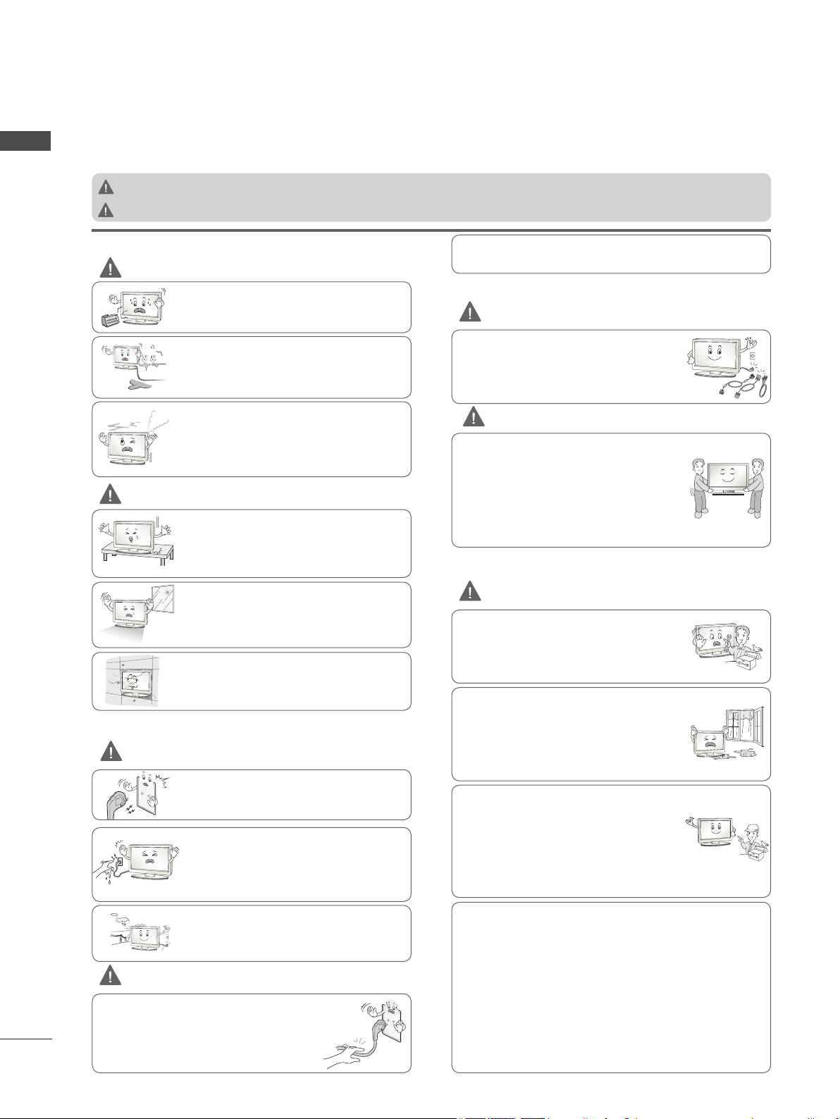
PRECAUTION IN INSTALLING THE PRODUCT
WARNING
Keep away from heat sources like electrical
heaters.
- Electrical shock, fire, malfunction or deformation may occur.
Do not use the product in damp place such as
a bathroom or any place where it is likely to get
wet.
- This may cause a fire or could give an electric
shock.
If you can smell smoke or other odors or hear
a strange sound unplug the power cord and
contact the service center.
- If you continue to use without taking proper
measures, electrical shock or fire can occur.
CAUTION
Install the product on a flat and stable place
that has no risk of dropping the product.
- If the product is dropped, you may be
injured or the product may be broken.
Keep the product away from direct sunlight.
- The product can be damaged.
Do not place the product in a built-in installation such as bookcase or rack.
- Ventilation required.
ELECTRICAL POWER RELATED PRECAUTIONS
WARNING
Make sure to connect the power cable to the
grounded current.
- You may be electrocuted or injured.
Do not touch the power plug with wet hands.
Additionally, it the cord pin is wet or covered
with dust, dry the power plug completely or
wipe dust off.
- You may be electrocuted due to excess
moisture.
During a thunder or lightning storm, unplug
the power cable or signal cable.
- You may be electrocuted or a fire can break
out.
CAUTION
Protect the power cord from physical or
mechanical abuse, such as being twisted,
kinked, pinched, closed in a door, or walked
upon. Pay particular attention to plugs, wall
outlets, and the point where the cord exits
the appliance.
2
As long as this unit is connected to the AC wall outlet, it is not
disconnected from the AC power source even if you turn off
this unit by SWITCH.
PRECAUTIONS IN MOVING THE PRODUCT
WARNING
Make sure to turn off the product.
Make sure to remove all cables before mov-
ing the product.
- You may be electrocuted or the product
can be damaged.
CAUTION
Do not shock the product when moving it.
- You may be electrocuted or the product
can be damaged.
Make the panel face forward and hold it
with both hands to move.
- If you drop the product, the damaged
product can cause electric shock or fire.
Contact with the service center for repair.
PRECAUTIONS IN USING THE PRODUCT
WARNING
Do not disassemble, repair or modify the
product at your own discretion.
- Fire or electric shock accident can occur.
- Contact the service center for check, calibration or repair.
To reduce the risk of fire or electric shock,
do not expose this apparatus to rain or
moisture.
Apparatus shall not be exposed to dripping
or splashing and no objects filled with liquids, such as vases, shall be placed on the
apparatus.
Refer all servicing to qualified service personnel. Servicing is required when the
apparatus has been damaged in any way,
such as power supply cord or plug is damaged, liquid has been spilled or objects
have fallen into the apparatus, the apparatus has been exposed to rain or moisture,
does not operate normally, or has been
dropped.
IMPORTANT INFORMATION TO PREVENT “IMAGE BURN /
BURN-IN” ON YOUR TELEVISION SCREEN
-
When a fixed image (e.g. logos, screen menus, video game,
computer display and teletext pages) is displayed on the television for an extended period it can become permanently imprinted on the screen. This phenomenon is known as “image burn” or
“burn-in”. Image burn is not covered under the manufacturer’s
warranty.
-
In order to prevent image burn, avoid displaying a fixed image on
your television’s screen for a prolonged period (2 or more hours
for LCD, 1 or more hours for Plasma).
-
Image burn can also occur on the letterboxed areas of your
television if you use the 4:3 aspect ratio setting for an extended
period.
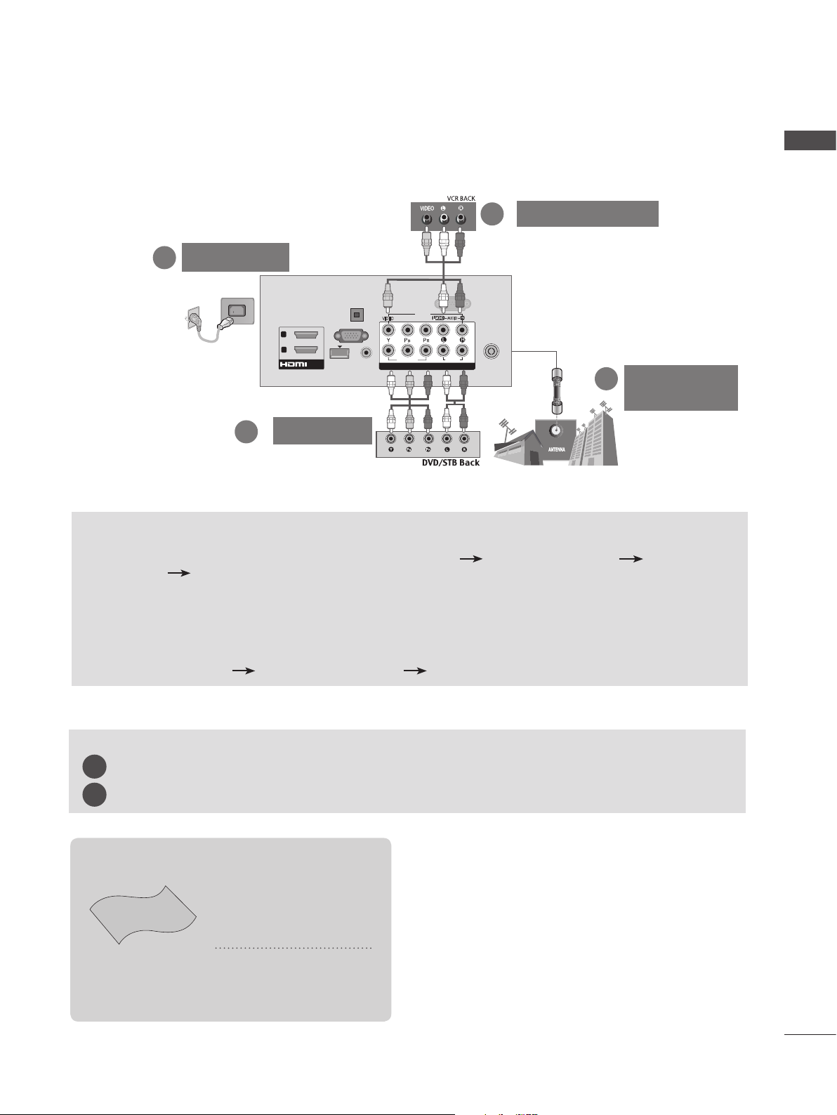
CONNECTING YOUR UNIT
■ Image shown may differ from your TV.
■ To connect an additional equipment, see the External equipment Setup section in CD Manual.
VCR Connection
2
Power Cord
3
RS-232C IN
AV IN1
VIDEO
COMPONENT IN
COMPONENT IN
(CONTROL & SERVICE)
R
AUDIO
L/MONO
AUDIO
2
1
ANTENNA /
CABLE IN
Antenna
1
Connection
OPTICAL
DIGITAL
AUDIO OUT
(PC)
AUDIO IN
(RGB/DVI)
VIDEO
/DVI IN
RGB IN
WIRELESS
CONTROL
2
1
ENGLISH
2
DVD/STB
TO VIEW THE USER'S GUIDE ON THE CD-ROM
To view the User's guide on the CD-ROM, Adobe Acrobat Reader must be installed on your PC.
The "ACRORD" folder on the CD-ROM contains the installation program for Acrobat Reader.
If you want to install Acrobat Reader, Open "My Computer" Open the folder "LG" Open the folder
"ACRORD" double-click your language.
To view the User's guide
The User's guide files are included in the supplied CD-ROM.
Load the supplied CD-ROM into the CD-ROM drive of your PC.
After a while, the web page of the CD-ROM will open automatically.(Windows users only)
If the web page does not appear automatically, open the User's guide file directly.
Open "My computer" Open the folder "LG" Double click the "index.htm" file.
TO VIEW THE SIMPLE MANUAL
You can easily and effectively access the TV information by viewing the simple manual on the TV.
Press the GREEN button, you can check the Simple manual menu.
1
Press the EXIT button to return to normal TV viewing.
2
This item is not included for all models.
* Lightly wipe any stains
or fingerprints on the
surface of the TV with
the polishing cloth.
Polishing Cloth
Polishing cloth for
use on the screen.
Do not use excessive
force. This may cause
scratching or discolouration.
3
PREPARATION
LIGHT
ENGLISH
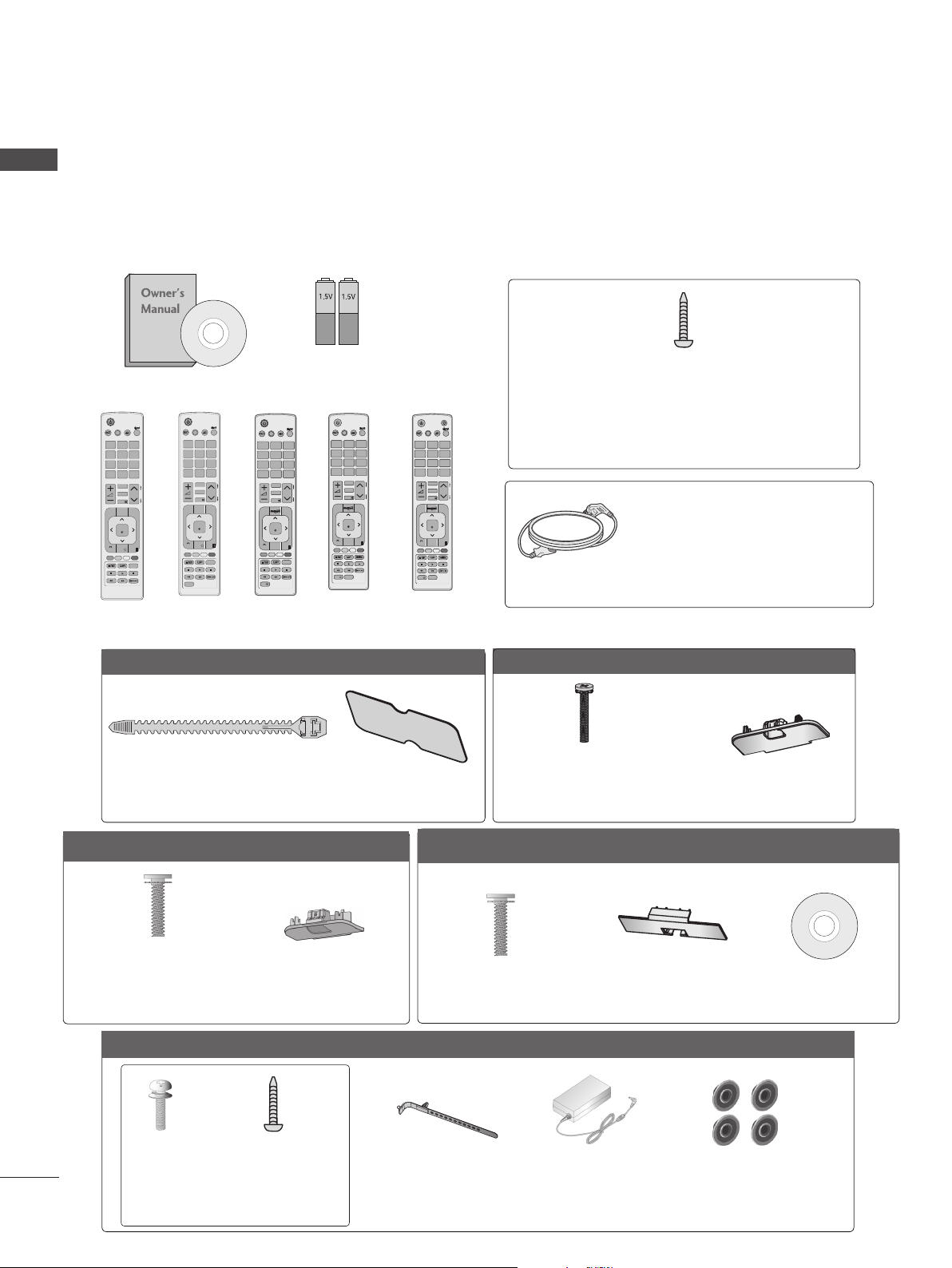
ACCESSORIES
Ensure that the following accessories are included with your TV. If an accessory is missing, please
contact the dealer where you purchased the TV.
ENERGY
SAVING
1 2 3
4 506
7 8 9
LIST
MENU
BACK
■ Image shown may differ from your TV.
Batteries
Owner’s Manual
AV MODE
INPUT
AV MODE
INPUT
Q.VIEW
MARK
FAV
RATIO
P
MUTE
GUIDE
Q.MENU
OK
EXIT
INFO i
SUBTITLE
ENERGY
SAVING
1 2 3
4 506
7 8 9
LIST
MENU
BACK
AD
TV/
RAD
Q.VIEW
MARK
FAV
RATIO
P
MUTE
GUIDE
Q.MENU
OK
EXIT
INFO i
SUBTITLE
TV/
RAD
or
P
A
G
E
AV MODE
ENERGY
SAVING
1 2 3
GHI
4 506
7 8 9
PQRS
LIST
or
P
A
G
E
MENU
BACK
INFO i
(AAA)
AV MODE
INPUT
INPUT
ABC
JKL
TUV
Q.VIEW
MARK
FAV
CHAR/NUM
RATIO
DELETE
MUTE
Q.MENU
OK
GUIDE
EXIT
SUBTITLE
ENERGY
SAVING
1 2 3
JKL
GHI
4 506
7 8 9
PQRS
LIST
MARK
FAV
CHAR/NUM
3D
DELETE
MUTE
MENU
OK
GUIDE
BACK
RATIO
INFO i
TV/
RAD
DEF
ABC
MNO
WXYZ
TUV
Q.VIEW
or
P
A
P
G
E
Q.MENU
EXIT
L/R SELECT
TV/
RAD
DEF
MNO
WXYZ
or
P
A
P
G
E
Remote Control
AV MODE
ENERGY
SAVING
1 2 3
JKL
GHI
4 506
7 8 9
PQRS
LIST
MARK
FAV
CHAR/NUM
3D
DELETE
MUTE
MENU
OK
GUIDE
BACK
RATIO
INFO i
1-screw for stand fixing
(Refer to p. 21)
LIGHT
INPUT
TV/
RAD
DEF
ABC
MNO
WXYZ
TUV
Q.VIEW
P
A
P
G
E
Q.MENU
(Only 26/32LD3**, 32/37/42LD4**,
32/42LD5**, 32/37/42LD6**, 32/42LE4***,
32LE5***)
(Except for
32/37/42/47/55/60LE5***,
EXIT
L/R SELECT
32/37/42/47/55LE7***,
42/47/55LE8***,
Power Cord
42/47/55LX6***, 47/55LX9***)
Only 22LD3**
Cable Holder
(Refer to p. 20)
Only 32/37/42/47LD4**
x 8
(M4 X 20)
Bolts for stand assembly
(Refer to p. 17)
Only 22/26LE53**
x 4
Protection Cover
(Refer to p. 22)
Protection Cover
(Refer to p. 22)
x 4
Only 26/32LD3**
x 8
(M4 X 20)
Bolts for stand assembly
(Refer to p. 17)
Only 32/42/46/52/60LD5**
x 8
(M4 X 20)
Bolts for stand assembly
(Refer to p. 17)
Protection Cover
(Refer to p. 22)
Protection Cover
(Refer to p. 22)
(Only 32/42/52LD56*)
Nero MediaHome
4 Essentials CD
(M4x14)
Bolts for stand assembly
4
(Refer to p. 18)
(M4x20)
(Only 26LE53**)
Cable Holder
(Refer to p. 21)
AC/DC Adaptor
(Refer to p. 23)
4-Ring spacers
(Only 26LE53**)
(Refer to p. 23)
Only 32/37/42/47/55LE53
**
x 4
(M4x22)
(Only 32LE53**)
x 4
(M4x24)
(Only
37/42LE53**)
x 4
(M4x26)
(Only
47/55LE53**)
x 4
(M4x16)
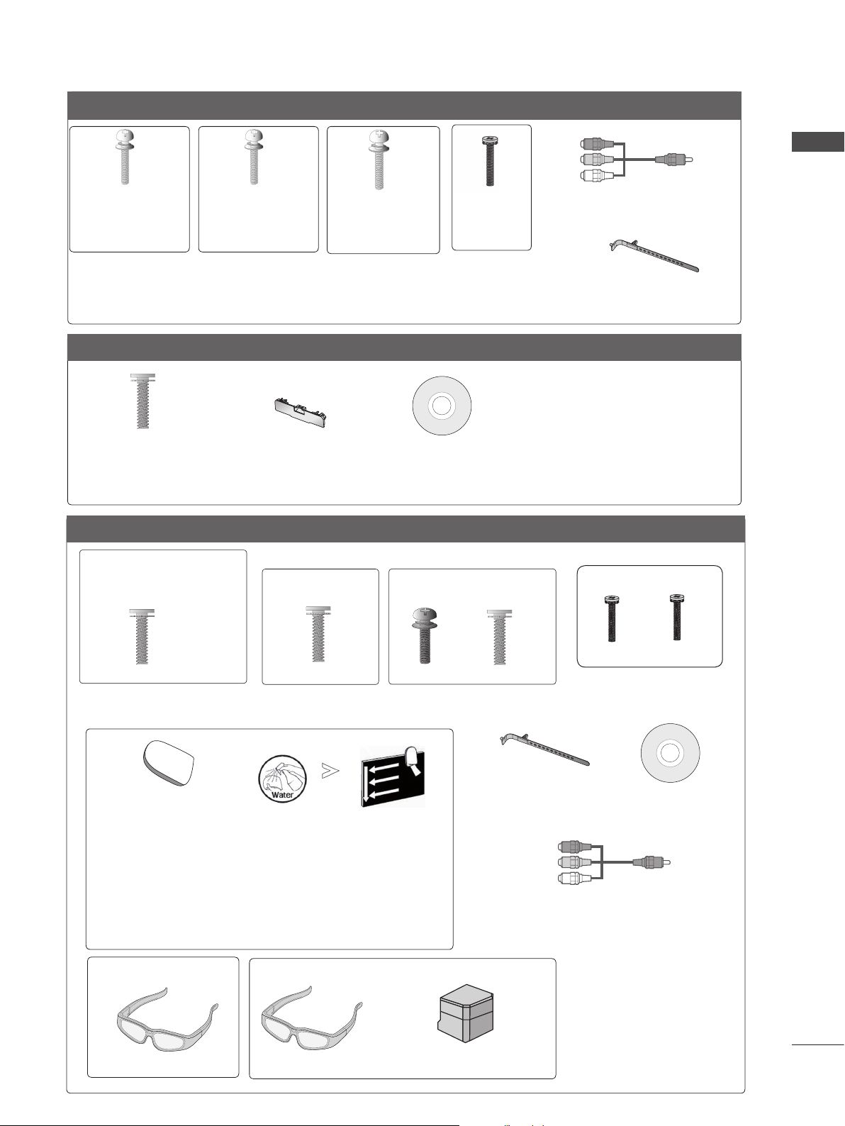
Component gender cable,
AV gender cable
x 2
Bolts for stand assembly (Refer to p. 18)
Cable Holder
(Refer to p. 21)
Only 32/37/42/47/55LD6**
x 8
(M4x20)
Bolts for stand assembly
(Refer to p. 17)
Protection cover
(Refer to p. 22)
Nero MediaHome
4 Essentials CD
Only 32/37/42/47/55/60LE55**, 32/37/42/47/55LE7***, 42/47/55LE8***, 42/47/55LX6***, 47/55LX9***
(Only 32/37/42/47LE55**,
32/37/42/47LE7
42/47LX6***)
***,
x 8
(M4 x 16)
Bolts for stand assembly
(Only 42/47/55LE8
x 8
(M4 x 20)
(Refer to p. 19)
***
)
(Only 55LE55**,
55LE7
***,
55LX6***)
x 4x 4
(M4 x 16)(M4 x 24)
(Only 47/55LX9***)
x 4
M4x12
x 4
M4x22
Bolts for stand assembly
(Refer to p. 20)
ENGLISH
cleansing cloths(mitt)
(Only 32/37/42/47/55LE7
***
)
Slightly wipe stained spot on the exterior only with
the cleansing cloths(mitt) for the product exterior if
there is stain or fingerprint on surface of the exterior.
For cleaning front frame, please slowly wipe in one
direction after spraying water 1~2 times on cleansing
cloths. Please remove excessive moisture after cleaning.
Excessive moisture may cause water stains on the frame.
(Only 42/47/55LX6
***
)
(Only 47/55LX9***)
x 2
3D Glasses
3D Glasses
Stand Rear Cover
Cable Holder
(Refer to p. 21)
Nero MediaHome
4 Essentials CD
Component gender cable,
AV gender cable
x 2
5
P
INPUT
MENU
OK
P
INPUT
MENU
OK
P
INPUT
MENU
OK
P
P
OK
MENU
INPUT
P
INPUT
MENU
PREPARATION
ENGLISH
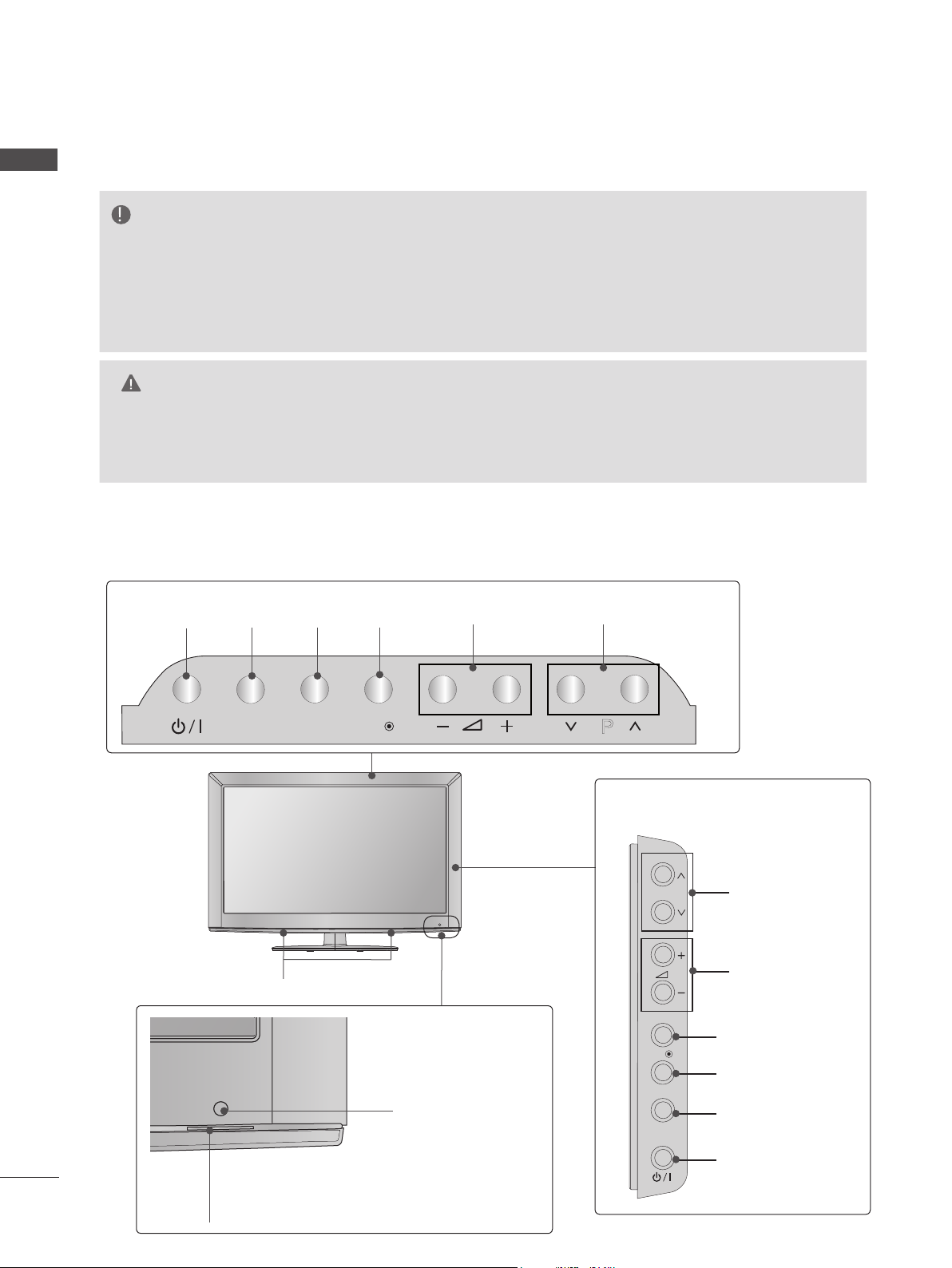
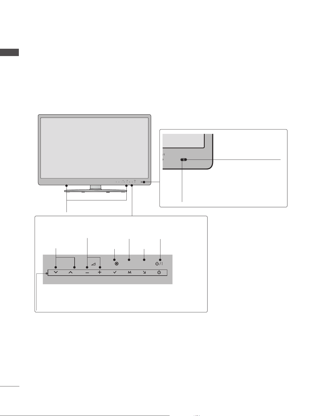
FRONT PANEL CONTROLS
■ Image shown may differ from your TV.
Only 22/26/32LD3**
NOTE
►
TV can be placed in standby mode in order to reduce the power consumption. And TV should
be switched off using the power switch on the TV if it will not be watched for some time, as this
will reduce energy consumption.
► The energy consumed during use can be significantly reduced if the level of brightness of the picture
is reduced, and this will reduce the overall running cost.
CAUTION
► Do not step on the glass stand or subject it to any impact. It may break, causing possible injury from frag-
ments of glass, or the TV may fall.
► Do not drag the TV. The floor or the product may be damaged.
Only 22LD3**
INPUTPOWER
OKMENU
PROGRAMMEVOLUME
INPUT
MENU
OK
P
Only 26/32LD3**
P
SPEAKER
Remote Control Sensor
OK
MENU
INPUT
Power/Standby Indicator
(Can be adjusted using the Power
6
Indicator in the OPTION menu.)
PROGRAMME
VOLUME
OK
MENU
INPUT
POWER
OK
P
P
OK
P
MENU
INPUT
■ Image shown may differ from your TV.
OK
P
MENU
INPUT
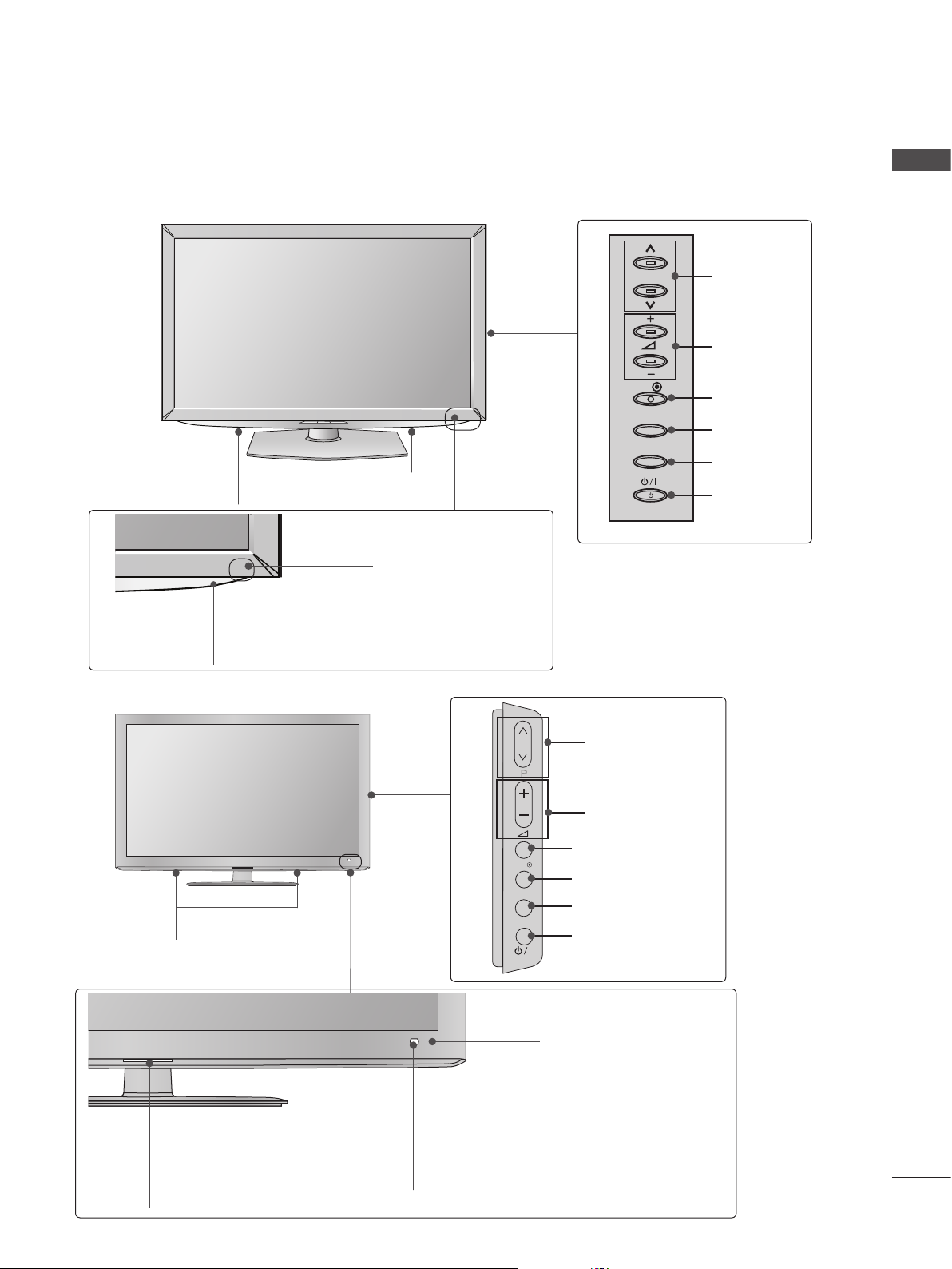
Only 32/37/42/47LD4**
ENGLISH
SPEAKER
Power/Standby Indicator
(Can be adjusted using the Power
Indicator in the OPTION menu.)
Only 32/42/46/52/60LD5**
Remote Control Sensor
OK
MENU
INPUT
P
PROGRAMME
VOLUME
OK
MENU
INPUT
POWER
SPEAKER
Power/Standby Indicator
(Can be adjusted using the Power
Indicator in the OPTION menu.)
PROGRAMME
P
VOLUME
OK
MENU
INPUT
OK
MENU
INPUT
POWER
Remote Control Sensor
Intelligent Sensor
Adjusts picture according to
the surrounding conditions.
7
PREPARATION
INPUT
MENU
OK
P
INPUT
MENU
OK
P
■ Image shown may differ from your TV.
ENGLISH
Only 32/37/42/47/55LD6**
SPEAKER
Power/Standby Indicator
(Can be adjusted using the Power Indicator in the
OPTION menu.)
Remote Control Sensor
Intelligent Sensor
Adjusts picture according to the surrounding conditions.
P
OK
MENU
INPUT
PROGRAMME
VOLUME
OK
MENU
INPUT
POWER
■ Image shown may differ from your TV.
Only 22/26LE53**
P
OK
SPEAKER
VOLUME MENU POWER
P
OK
MENU
INPUT
OKPROGRAMME
INPUT
Power/Standby Indicator
(Can be adjusted using the
Power Indicator in the
OPTION menu.)
MENU
INPUT
U
INPUT
Remote Control Sensor
8
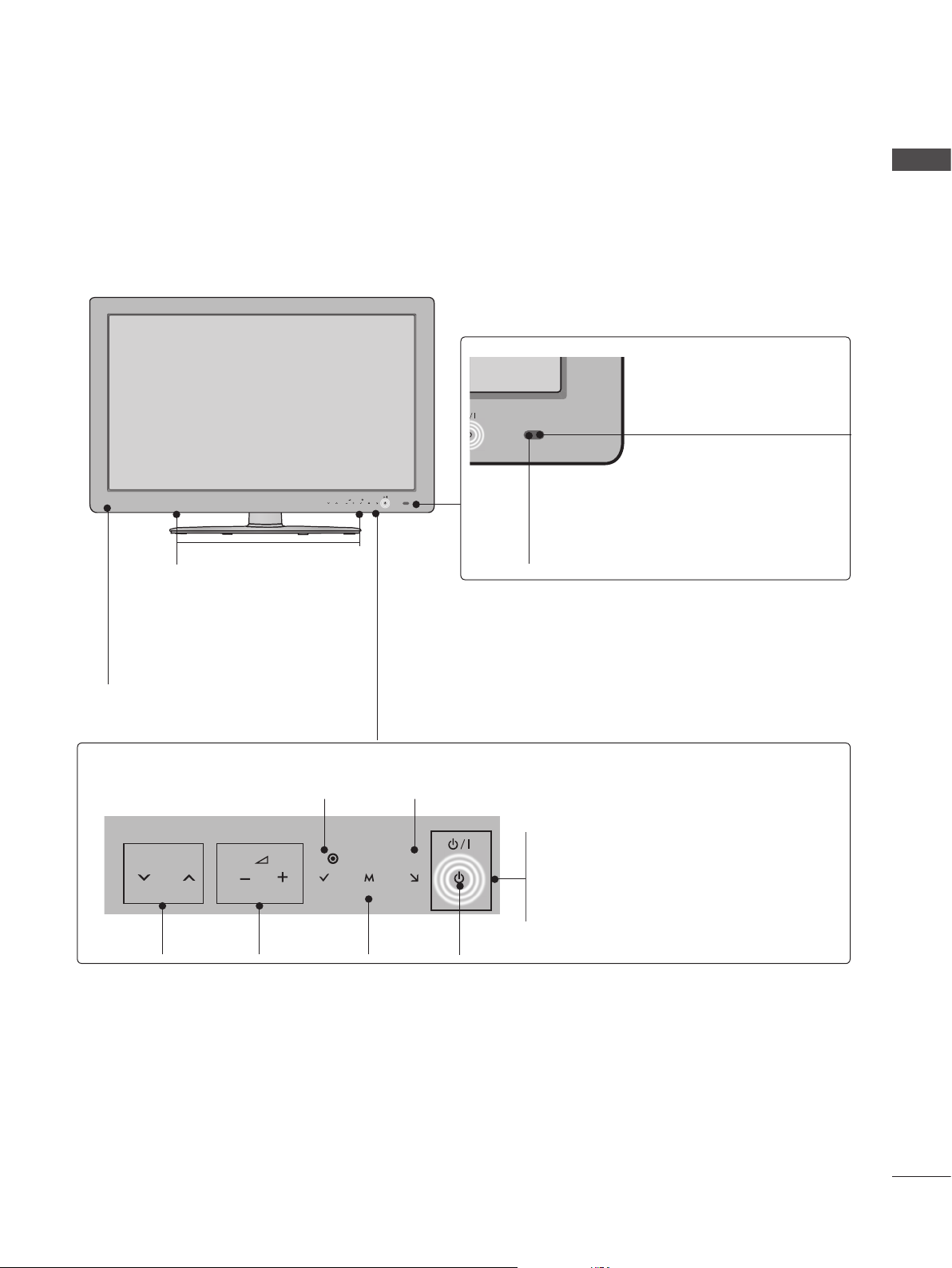
■ Image shown may differ from your TV.
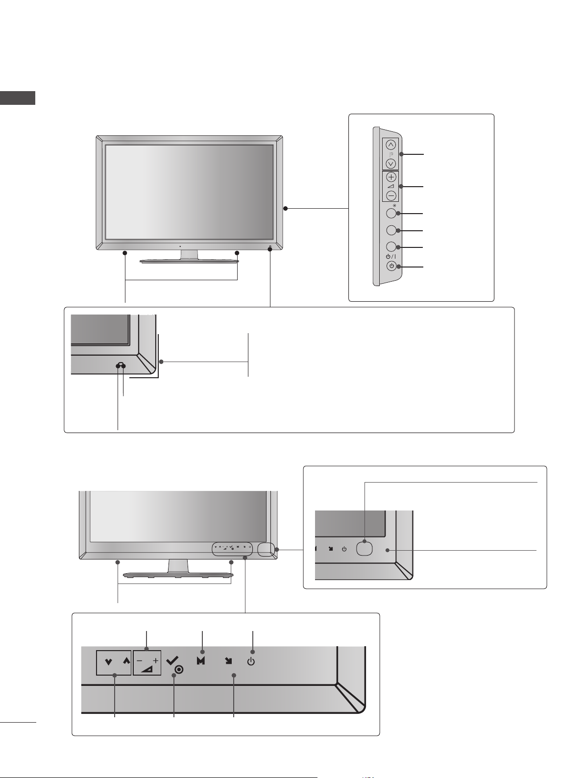
Only 32/37/42/47/55/60LE5***, 32/37/42/47/55LE7***, 42/47/55LX6***
P
MENU
OK
INPUT
ENGLISH
Intelligent Sensor
Adjusts picture according to
the surrounding conditions.
SPEAKER
Emitter (Only 42/47/55LX6
***
)
It is the part equipped with the emitter
exchanging signal with 3D glasses.
Please be careful not to block
the screen with objects or people
while watching a 3D Video.
Touch Sensor
• You can use the desired button function by touching.
INPUTOK
P
PROGRAMME
VOLUME
OK
MENU
MENU
INPUT
POWER
Remote Control Sensor
Power/Standby Indicator
(Can be adjusted using the Power
Indicator in the OPTION menu.)
9
ENGLISH
Only 42/47/55LE8***
■ Image shown may differ from your TV.
MENU
P
OK
SPEAKER
Intelligent Sensor
Adjusts picture according to
the surrounding conditions.
INPUT
Remote Control Sensor
Touch Sensor
• You can use the desired button function by touching.
PROGRAMME
P
VOLUME
OK
MENU
MENU
POWER
INPUTOK
INPUT
Power/Standby Indicator
(Can be adjusted using the Power Indicator in the OPTION
menu.)
10
■ Image shown may differ from your TV.
Only 47/55LX9***
SPEAKER
ENGLISH
PROGRAMME
VOLUME
OK
MENU
INPUT
POWER
Emitter
It is the part equipped with the
emitter exchanging signal with 3D
glasses.
Please be careful not to block
the screen with objects or
people while watching a 3D
Video.
Intelligent Sensor
Adjusts picture according to
the surrounding conditions.
Remote Control Sensor
Power/Standby Indicator
(Can be adjusted using the Power Indicator
in the OPTION menu.)
11
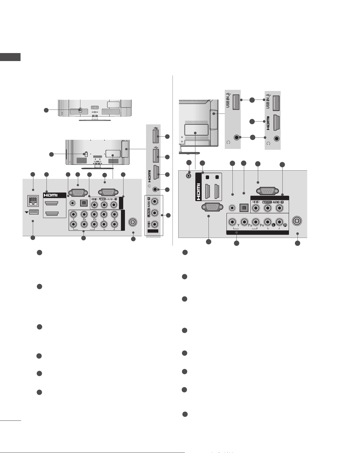
PREPARATION
H/P
AV IN2
IN 2
SERVICE ONLY
K
AC-IN
H/P
SERVICE ONLY
ENGLISH
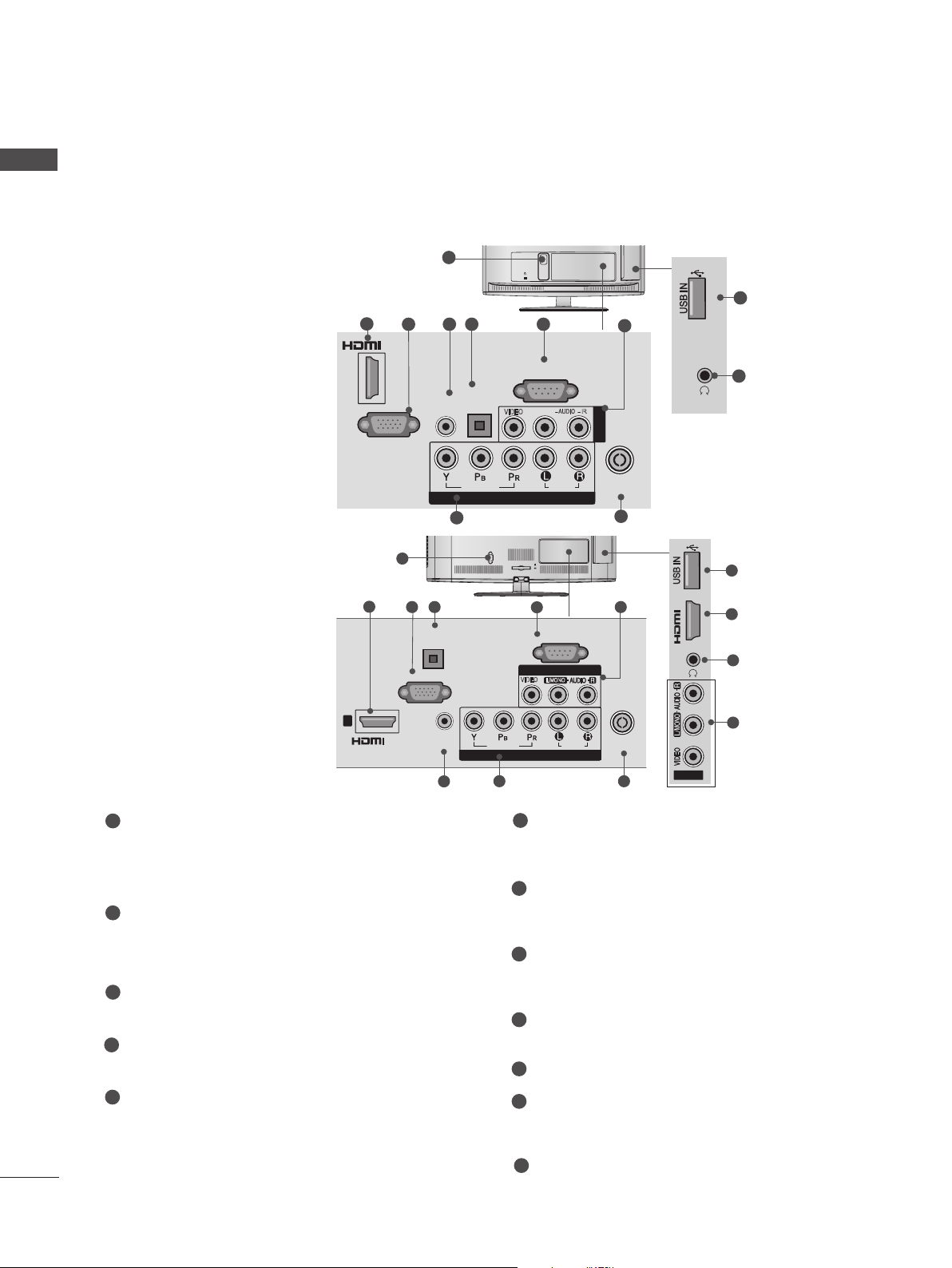
BACK PANEL INFORMATION
Only 22LD3**
Only 26/32LD3**
■ Image shown may differ from your TV.
2
/DVI IN
RGB IN
(PC)
2
1
3 4 5 6
(CONTROL & SERVICE)
OPTICAL
AUDIO IN
DIGITAL
AUDIO OUT
1
3 5
RGB IN
(RGB/DVI)
OPTICAL
DIGITAL
AUDIO OUT
(PC)
8
VIDEO
VIDEO
COMPONENT IN
AC IN
CABLE MANAGEMENT
VIDEO
RS-232C IN
AUDIO
L(MONO)
AUDIO
6
RS-232C IN
(CONTROL & SERVICE)
AV IN 1
L/MONO
R
AV IN
ANTENNA /
CABEL IN
10
IN 2
H/P
H/P
SERVICE ONLY
11
12
SERVICE ONLY
2
11
7
9
7
12
1
/DVI IN
1
Power Cord Socket
This TV operates on an AC power. The voltage is indicated on the Specifications page.
Never attempt to operate the TV on DC
power.
2
HDMI/DVI IN Input
Connect an HDMI signal to HDMI IN. Or DVI
(VIDEO) signal to HDMI/DVI port with DVI to
HDMI cable.
3
RGB IN Input
Connect the output from a PC.
4
RGB/DVI Audio Input
Connect the audio from a PC or DTV.
5
OPTICAL DIGITAL AUDIO OUT
Connect digital audio to various types of
equipment.
AUDIO IN
(RGB/DVI)
4
ANTENNA /
VIDEO
COMPONENT IN
8
AUDIO
CABLE IN
9
6
RS-232C IN (CONTROL & SERVICE) PORT
AV IN2
Connect to the RS-232C port on a PC.
This port is used for Service or Hotel mode.
7
Audio/Video Input
Connect audio/video output from an external
device to these jacks.
8
Component Input
Connect a component video/audio device to
these jacks.
9
Antenna / Cable Input
Connect antenna or cable to this jack.
10
SERVICE ONLY PORT
11
Headphone Socket
Plug the headphone into the headphone
socket.
7
Connect to a Digital Audio Component.
Use an Optical audio cable.
12
USB Input
Connect USB storage device to this jack.
■ Image shown may differ from your TV.
IN 3
H/P
R
AUDIO
HDMI IN 2 USB IN
H/P
H/P
AV IN2
IN 2
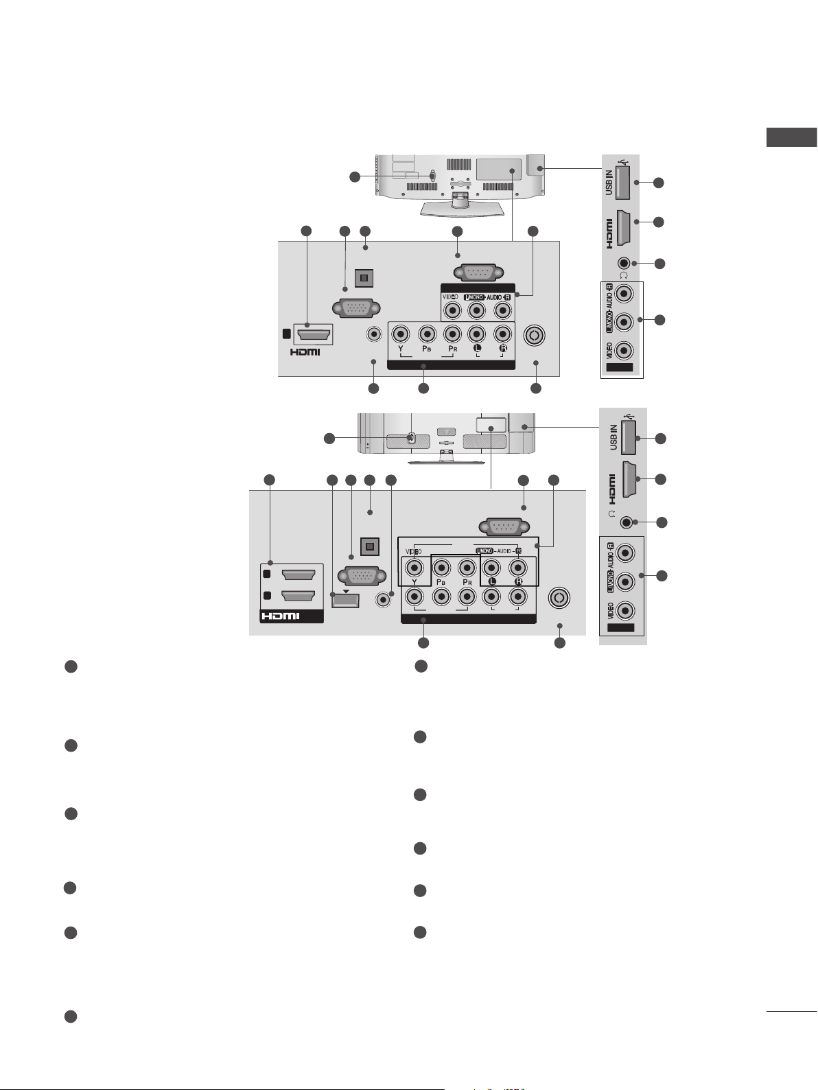
Only 32/37/42/47LD4**
ENGLISH
1
11
2
1
/DVI IN
Only 32/42/46/52/60LD55*
1
2
2
1
/DVI IN
1
Power Cord Socket
This TV operates on an AC power. The voltage is indicated on the Specifications page.
Never attempt to operate the TV on DC
power.
2
HDMI/DVI IN Input
Connect an HDMI signal to HDMI IN. Or DVI
(VIDEO) signal to HDMI/DVI port with DVI to
HDMI cable.
3
WIRELESS Control
Connect the Wireless Dongle to the TV to
control the external input devices connected
to Media Box wirelessly.
4
RGB IN Input
Connect the output from a PC.
4 5
OPTICAL
DIGITAL
AUDIO OUT
RGB IN
(PC)
AUDIO IN
(RGB/DVI)
6
3 4 5 6
OPTICAL
DIGITAL
AUDIO OUT
RGB IN
(PC)
WIRELESS
AUDIO IN
CONTROL
(RGB/DVI)
IN 2
7
RS-232C IN
(CONTROL & SERVICE)
AV IN 1
VIDEO
L/MONO
VIDEO
COMPONENT IN
9
AC IN
VIDEO
VIDEO
9
7
RS-232C IN (CONTROL & SERVICE) PORT
AUDIO
CABLE MANAGEMENT
(CONTROL & SERVICE)
AV IN1
L/MONO
COMPONENT IN
COMPONENT IN
RS-232C IN
AUDIO
AUDIO
8
ANTENNA /
CABLE IN
10
7
R
2
1
8
ANTENNA /
CABLE IN
10
H/P
AV IN2
IN 3
H/P
AV IN2
Connect to the RS-232C port on a PC.
This port is used for Service or Hotel mode.
8
Audio/Video Input
Connect audio/video output from an external
device to these jacks.
9
Component Input
Connect a component video/audio device to
these jacks.
10
Antenna / Cable Input
Connect antenna or cable to this jack.
11
USB Input
Connect USB storage device to this jack.
2
12
8
11
2
12
8
5
OPTICAL DIGITAL AUDIO OUT
Connect digital audio to various types of
equipment.
Connect to a Digital Audio Component.
Use an Optical audio cable.
6
RGB/DVI Audio Input
Connect the audio from a PC or DTV.
12
Headphone Socket
Plug the headphone into the headphone
socket.
13
PREPARATION
H/P
IN 3
H/P
IN 3
H/P
HDMI IN 3 USB IN 1
USB IN 2
h}GpuY
puGZ
H/P
USB IN 1
USB IN 2
ENGLISH
Only 32/42/52LD56*, 32/37/42/47/55LD6**
2
LAN
WIRELESS
CONTROL
9
1
2
3
■ Image shown may differ from your TV.
1
AC IN
CABLE MANAGEMENT
or
USB IN 2
RGB IN
(PC)
OPTICAL DIGITAL
AUDIO OUT
VIDEO
10
AC IN
6
VIDEO
CABLE MANAGEMENT
7
RS-232C IN
(CONTROL & SERVICE)
R
AUDIO
L(MONO)
AUDIO
AV IN 1
2
1
8
COMPONENT IN
ANTENNA /
CABLE IN
11
USB IN 1
puGZ
H/P
h}GpuY
1
3 54
/DVI IN
2
1
RGB/DVI
AUDIO IN
Power Cord Socket
This TV operates on an AC power. The voltage is indicated on the Specifications page.
Never attempt to operate the TV on DC
power.
LAN
Network connection for Weather info, Photo
Album, Movie Online, etc.
Also used for video, photo and music files on
a local network.
HDMI/DVI IN Input
Connect an HDMI signal to HDMI IN. Or DVI
(VIDEO) signal to HDMI/DVI port with DVI to
HDMI cable.
Only 22/26LE53**
12
12
14
3
13
8
DC-IN
7
RS-232C IN (CONTROL & SERVICE) PORT
Connect to the RS-232C port on a PC.
This port is used for Service or Hotel mode.
8
Audio/Video Input
Connect audio/video output from an external
device to these jacks.
9
WIRELESS Control
Connect the Wireless Dongle to the TV to
control the external input devices connected
to Media Box wirelessly.
10
Component Input
Connect a component video/audio device to
these jacks.
H/P
Only 22LE53**
/DVI IN
3
(DVI)
RGB IN
1
5
2
(PC)
4
AUDIO IN
(RGB/DVI)
12
2
13
IN 3
H/P
Only 26LE53**
6
7
RS-232C IN
(CONTROL & SERVICE)
OPTICAL
DIGITAL
VIDEO
AUDIO OUT
VIDEO
COMPONENT IN
10 11
L(MONO)
AV IN
AUDIO
8
ANTENNA /
CABLE IN
14
4
RGB/DVI Audio Input
Connect the audio from a PC or DTV.
5
RGB IN Input
Connect the output from a PC.
6
OPTICAL DIGITAL AUDIO OUT
Connect digital audio to various types of
equipment.
Connect to a Digital Audio Component.
Use an Optical audio cable.
11
Antenna / Cable Input
Connect antenna or cable to this jack.
12
USB Input
Connect USB storage device to this jack.
13
Headphone Socket
Plug the headphone into the headphone
socket.
14
DC ADAPTER PORT
Connect to the power cord socket.
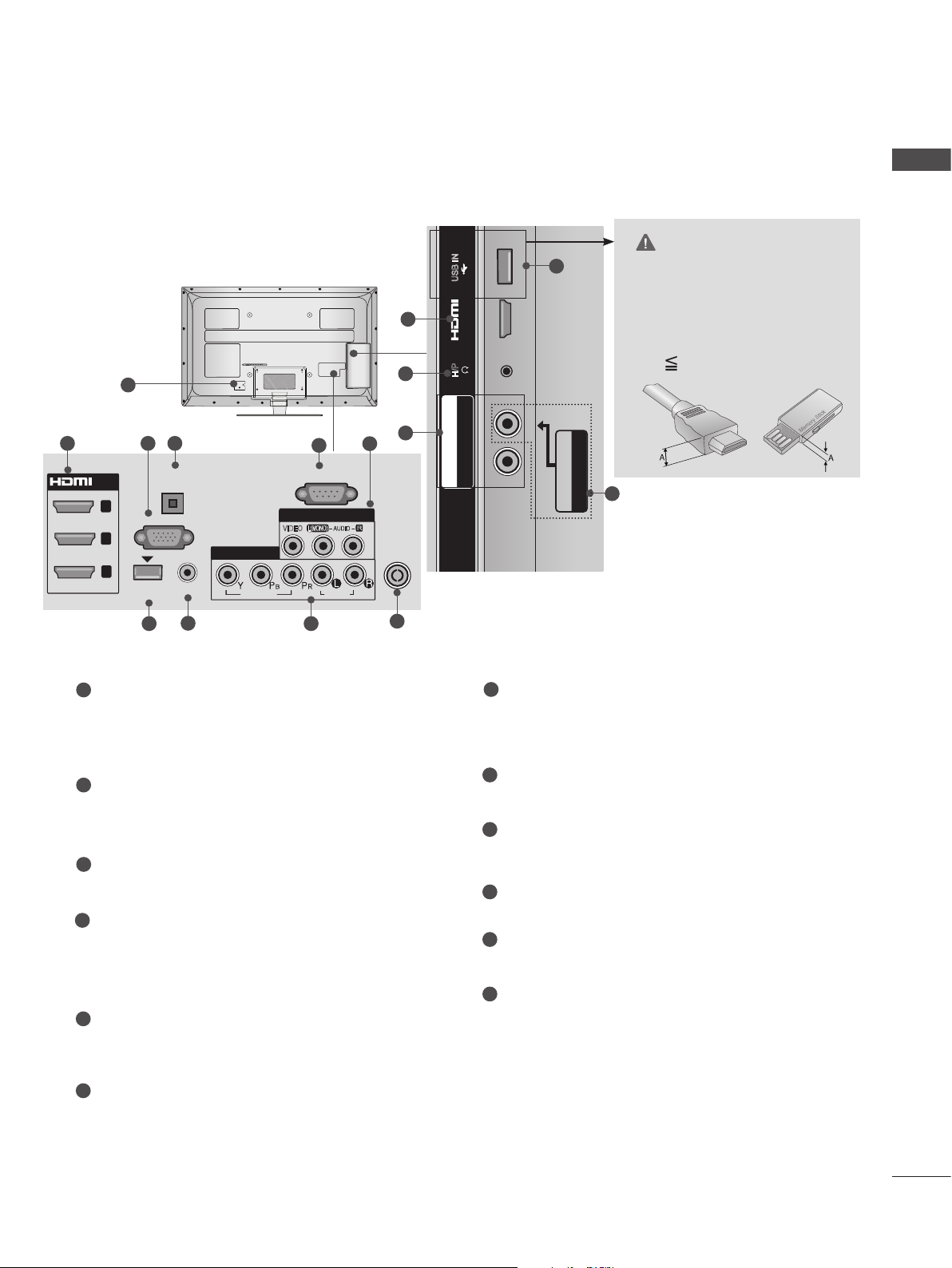
■ Image shown may differ from your TV.
H/P
USB IN
/ AUDIO
IN 4
Y PB PR
USB IN 2
USB IN 1
Only 32/37/42/47/55LE53**
1
ENGLISH
CAUTION
USB IN
2
12
IN 4
H/P
11
► Use a product with the follow-
ing thickness for optimal connection to HDMI cable(only
HDMI IN 4) / USB device.
*A 10 mm
2 43
OPTICAL
/DVI IN
3
2
1
(DVI)
1
Power Cord Socket
DIGITAL
AUDIO OUT
RGB IN
WIRELESS
CONTROL
7 9
(PC)
AUDIO IN
(RGB/DVI)
8
COMPONENT IN1
VIDEO
5
RS-232C IN
(CONTROL & SERVICE)
AV IN 1
L(MONO)
VIDEO
AUDIO
AUDIO
This TV operates on an AC power. The voltage is indicated on the Specifications page.
Never attempt to operate the TV on DC
power.
HDMI/DVI IN Input
2
Connect an HDMI signal to HDMI IN. Or DVI
(VIDEO) signal to HDMI/DVI port with DVI to
HDMI cable.
3
RGB IN Input
Connect the output from a PC.
OPTICAL DIGITAL AUDIO OUT
4
Connect digital audio to various types of
equipment.
Connect to a Digital Audio Component.
Use an Optical audio cable.
5
RS-232C IN (CONTROL & SERVICE) PORT
Connect to the RS-232C port on a PC.
This port is used for Service or Hotel mode.
R
6
9
ANTENNA /
CABLE IN
10
/ AUDIO
Y PB PR
COMPONENT IN2
7
WIRELESS Control
Connect the Wireless Dongle to the TV to
control the external input devices connected
to Media Box wirelessly.
8
RGB/DVI Audio Input
Connect the audio from a PC or DTV.
9
Component Input
Connect a component video/audio device to
these jacks.
10
Antenna / Cable Input
Connect antenna or cable to this jack.
11
USB Input
Connect USB storage device to this jack.
Headphone Socket
12
Plug the headphone into the headphone
socket.
AV IN2
VIDEO / AUDIO
6
6
Audio/Video Input
Connect audio/video output from an external
device to these jacks.
15
 Loading...