

LG HU161HA INSTALLATION MANUAL
INSTALLATION MANUAL
ENGLISH
POLSKI
FRANÇAIS
ČEŠTINA
ΕΛΛΗΝΙΚΆ
PORTUGUÊS
AIR-TO-WATER
HEAT PUMP
Please read this installation manual completely before installing the
product. Installation work must be performed in accordance with the
national wiring standards by authorized personnel only. Please retain
this installation manual for future reference after reading it thoroughly.
(For High temp. model only)
Original instruction
MAGYAR
БЪЛГАРСКИ
SRPSKI HRVATSKI
SLOVENŠČINA
ESPAÑOL
MFL67212828
Rev.05_082720
www.lg.com
Copyright © 2019 - 2020 LG Electronics Inc. All Rights Reserved.

TABLE OF CONTENTS
2
ENGLISH
TABLE OF CONTENTS
4 PREFACE
5 SAFETY INSTRUCTIONS
12 INSTALLATION PART
13 GENERAL INFORMATION
13 Model Information
15 Model name and related information
16 Parts and Dimensions
19 Control Parts
20 Control Panel
23 Typical Installation Example
24 Cycle Diagram
25 INSTALLATION
25 Transporting the Unit
26 Selection of the best location
28 Installation Space
32 Collective / Continuous Installation for roof top use
33 Installation at Seaside
33 Seasonal wind and cautions in winter
34 Foundation for Installation
35 INSTALLATION OF INDOOR UNIT
35 Electrical Wiring
38 PIPING AND WIRING FOR OUTDOOR UNIT
38 Refrigerant Piping
38 Drill a Hole in the Wall
39 Preparation for Piping
40 Connecting Pipe to Indoor Unit
40 Connecting Pipe to Outdoor Unit
43 Finalizing
44 Leakage test and Evacuation
46 Electrical Wiring
49 PIPING AND WIRING FOR INDOOR UNIT
49 Water Piping and Water Circuit Connection
53 Water pump Capacity
53 Water Quality
54 Frost protection
55 ACCESSORIES INSTALLATION
57 Before Installation
57 Thermostat
60 3rd Party Controller
61 Central Controller
62 DHW Tank
63 Dry Contact
65 External Controller - Setting up programmable digital input operation
66 Remote Temperature Sensor
68 External pump

69 Wi-fi Modem
70 Smart Grid
71 3Way Valve(A)
72 Wired Remote Controller
74 CONFIGURATION
74 DIP Switch Setting
80 SERVICE SETTING
80 How to enter service setting
80 Service setting
81 Service contact
82 Model information
83 RMC version lnformation
84 Open source license
85 INSTALLER SETTING
85 How to enter installer setting
86 Installer setting
88 3 Minutes Delay
89 Select Temperature Sensor
90 Dry Contact Mode
91 Central Control Address
92 Pump test run
93 Air heating set temp.
94 Water heating set temp
95 DHW set temp
96 Outdoor temp. for auto mode
97 Indoor air temp. for auto mode
98 LWT temp. for auto mode
99 Tank disinfection setting 1, 2
100 Tank setting 1
101 Tank setting 2
102 DHW time setting
103 TH on/off Variable, heating air
104 TH on/off Variable, heating water
105 Heating temp. setting
106 Pump setting in heating
107 Forced operation
108 CN_CC
109 Smart Grid(SG)
110 IDU Address Verification
111 CN_EXT
112 Use External Pump
113 Pump Prerun/Overrun
114 Data logging
115 Password Initialization
116 Power Supply Blockage (SG Ready)
117 Overview settings
TABLE OF CONTENTS
3
ENGLISH
119 COMMISSIONING
119 Check List before Starting Operation
120 Starting Operation
121 Starting Operation flow chart
121 Airborne Noise Emission
121 Limiting concentration(R410A)
122 Troubleshooting
PREFACE
4
ENGLISH
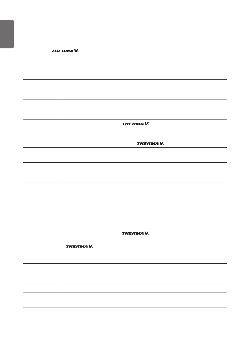
PREFACE
This installation manual is to present information and guide about understanding, installing,
and checking .
Your careful reading before installation is highly appreciated to make no mistake and to prevent
potential risks. The manual is divided into ten chapters. These chapters are classified according to
installation procedure. See the table below to get summarized information.
Chapters Contents
• Warning and Caution concerned with safety.
Chapter 1
Chapter 2
Chapter 3
Chapter 4
Chapter 5
Chapter 6
Chapter 7
• This chapter is directly related with human safety. We strongly recommend reading this
chapter carefully.
• Items Inside product Box
• Before starting installation, please make it sure that all parts are found inside the product
box.
• Fundamental knowledge about
• Model identification, accessories information, refrigerant and water cycle diagram, parts
and dimensions, electrical wiring diagrams, etc.
• This chapter is important to understand
• Installation about the outdoor unit.
• Installation location, constraints on installation site, etc
• Installation about the indoor unit.
• Installation location, constraints on installation site, etc
• Constrains when accessories are installed
• How to perform piping (for refrigerant) and wiring at the outdoor unit.
• Refrigerant pipe connection between the indoor unit and the outdoor unit.
• Electrical wiring at the outdoor unit.
• How to perform piping (for water) and wiring at the indoor unit.
• Water pipe connection between the indoor unit and pre-built under floor water loop pipe.
• Electrical wiring at the indoor unit.
• System set-up and configuration.
• As many control parameters of is adjustable by control panel, deep
understanding about this chapter is required to secure the operation flexibility of
• For more detailed information, please read the separate operation manual to use control
panel and adjust control parameters.
• Information about supported accessories
Chapter 8
Chapter 9
Chapter 10
REMARK : ALL CONTENTS OF THIS MANUAL ARE SUBJECT TO CHANGE WITHOUT NOTICE.
• Specification, Constraints, and wiring are described.
• Before purchasing accessories, please find supported specification to buy proper one.
• Test operation and check point while test running.
• Check points before starting operation are explained.
• Troubleshooting, maintenance, and error code list are presented to correct problems.
TO GET THE LATEST INFORMATION, PLEASE VISIT LG ELECTRONICS WEB SITE.
SAFETY INSTRUCTIONS
SAFETY INSTRUCTIONS
The following safety guidelines are intended to prevent
unforeseen risks or damage from unsafe or incorrect operation
of the appliance.
The guidelines are separated into ‘WARNING’ and ‘CAUTION’ as
described below.
This symbol is displayed to indicate matters and operations
!
that can cause risk.
Read the part with this symbol carefully and follow the
instructions in order to avoid risk.
WARNING
!
This indicates that the failure to follow the instructions can cause
serious injury or death.
CAUTION
!
This indicates that the failure to follow the instructions can cause
the minor injury or damage to the product.
5
ENGLISH
WARNING
!
Installation
• Do not use a defective or underrated circuit breaker. Use this
appliance on a dedicated circuit.
- There is risk of fire or electric shock.
• For electrical work, contact the dealer, seller, a qualified
electrician, or an Authorized Service Center.
- There is risk of fire or electric shock.
• Always ground the unit.
- There is risk of fire or electric shock.
• Install the panel and the cover of control box securely.
- There is risk of fire or electric shock.
• Always install a dedicated circuit and breaker.
-
Improper wiring or installation may cause fire or electric shock.

SAFETY INSTRUCTIONS
6
ENGLISH
• Use the correctly rated breaker or fuse.
- There is risk of fire or electric.
• Do not modify or extend the power cable.
- There is risk of fire or electric shock.
• Do not install, remove, or reinstall the unit by yourself
(customer).
- There is risk of fire, electric shock, explosion, or injury
• For antifreeze, always contact the dealer or an authorized
service center.
- Almost the antifreeze is a toxic product.
• For installation, always contact the dealer or an authorized
Service Center.
- There is risk of fire, electric shock, explosion, or injury.
• Do not install the unit on a defective installation stand.
- It may cause injury, accident, or damage to the unit.
• Be sure the installation area does not deteriorate with age.
- If the base collapses, the unit could fall with it, causing
property damage, unit failure, and personal injury.
• Do not install the water pipe system as Open loop type.
- It may cause failure of unit.
• Use a vacuum pump or inert (nitrogen) gas when doing
leakage test or purging air. Do not compress air or oxygen and
do not use flammable gases.
- There is the risk of death, injury, fire or explosion.
• Make sure the connected condition of connector in product
after maintenance.
- Otherwise, it may cause product damage.
• Do not touch leaked refrigerant directly.
- There is risk of frostbite.
• Copper in contact with refrigerants shall be oxygen-free or
deoxidized, for example Cu-DHP as specified in EN 12735-1
and EN 12735-2.
• Compliance with national gas regulations shall be observed.
• Refrigerant tubing shall be protected or enclosed to avoid
damage.
• The installation of pipe-work shall be kept to a minimum.

SAFETY INSTRUCTIONS
• A brazed, welded, or mechanical connection shall be made
before opening the valves to permit refrigerant to flow
between the refrigerating system parts. A vacuum valve shall
be provided to evacuate the interconnecting pipe and/or any
uncharged refrigerating system part.
•
Any person who is involved with working on or breaking into a
refrigerant circuit should hold a current valid certificate from an
industry-accredited assessment authority, which authorises
their competence to handle refrigerants safely in accordance
with an industry recognised assessment specification.
• Do not use means to accelerate the defrosting process or to
clean, other than those recommended by the manufacturer.
• Do not pierce or burn.
• Be aware that refrigerants may not contain an odour.
• Dismantling the unit, treatment of the refrigerant oil and
eventual parts should be done in accordance with local and
national standards.
• Flexible refrigerant connectors (such as connecting lines
between the indoor and outdoor unit) that may be displaced
during normal operations shall be protected against mechanical
damage.
• Pipe-work shall be protected from physical damage.
• Mechanical connections (mechanical connectors or flared
joints) shall be accessible for maintenance purposes.
7
ENGLISH
Operation
• Take care to ensure that power cable could not be pulled out
or damaged during operation.
- There is risk of fire or electric shock.
• Do not place anything on the power cable.
- There is risk of fire or electric shock.
• Do not plug or unplug the power supply plug during operation.
- There is risk of fire or electric shock.
• Do not touch (operate) the unit with wet hands.
- There is risk of fire or electric shock.

SAFETY INSTRUCTIONS
8
ENGLISH
• Do not place a heater or other appliances near the power
cable.
- There is risk of fire or electric shock.
• Do not allow water to run into electric parts.
- There is risk of fire, failure of the unit, or electric shock.
• Do not store or use flammable gas or combustibles near the
unit.
- There is risk of fire or failure of unit.
• Do not use the unit in a tightly closed space for a long time.
- It may cause damage to the unit.
• When flammable gas leaks, turn off the gas and open a
window for ventilation before turning the unit on.
- There is risk of explosion or fire.
• If strange sounds, or smell or smoke comes from unit, turn the
breaker off or disconnect the power supply cable.
- There is risk of electric shock or fire.
• Stop operation and close the window in storm or hurricane. If
possible, remove the unit from the window before the
hurricane arrives.
- There is risk of property damage, failure of unit, or electric
shock.
• Do not open the front cover of the unit while operation. (Do
not touch the electrostatic filter, if the unit is so equipped.)
- There is risk of physical injury, electric shock, or unit failure.
• Do not touch any electric part with wet hands. you should be
power off before touching electric part.
- There is risk of electric shock or fire.
• Do not touch refrigerant pipe and water pipe or any internal
parts while the unit is operating or immediately after operation.
- There is risk of burns or frostbite, personal injury.
• If you touch the pipe or internal parts, you should be wear
protection or wait time to return to normal temperature.
- Otherwise , it may cause burns or frostbite, personal injury.
• Turn the main power on 6 hours ago before the product
starting operation.
- Otherwise, it may cause compressor damage.

SAFETY INSTRUCTIONS
• Do not touch electric parts for 10 minutes after main power
off.
- There is risk of physical injury, electric shock.
• The inside heater of product may operate during stop mode. It
is intended to protect the product.
• Be careful that some part of the control box are hot.
- There is risk of physical injury or burns.
• When the unit is soaked (flooded or submerged), contact an
Authorized Service Center.
- There is risk of fire or electric shock.
• Be cautious that water could not be poured to the unit directly.
- There is risk of fire, electric shock, or unit damage.
• Ventilate the unit from time to time when operating it together
with a stove, etc.
- There is risk of fire or electric shock.
• Turn the main power off when cleaning or maintaining the unit.
- There is risk of electric shock.
• Take care to ensure that nobody could step on or fall onto the
unit.
- This could result in personal injury and unit damage.
• If the unit is not used for long time, we strongly recommend
not to switch off the power supply to the unit.
- There is risk of water freezing.
• The appliance shall be stored in a well-ventilated area where
the room size corresponds to the room area as specified for
operation.
• The appliance shall be stored in a room without continuously
operating open flames (for example an operating gas
appliance) and ignition sources (for example an operating
electric heater).
• The appliance shall be stored so as to prevent mechanical
damage from occurring.
• Servicing shall only be performed as recommended by the
equipment manufacturer. Maintenance and repair requiring the
assistance of other skilled personnel shall be carried out under
the supervision of the person competent in the use of flammable
refrigerants.
9
ENGLISH

SAFETY INSTRUCTIONS
10
ENGLISH
• When mechanical connectors are reused indoors, sealing parts
shall be renewed. When flared joints are reused indoors, the
flare part shall be re-fabricated.
• Periodic(more than once/year) cleaning of the dust or salt
particles stuck on the heat exchangers by using water.
• Keep any required ventilation openings clear of obstruction.
CAUTION
!
Installation
• Always check for gas (refrigerant) leakage after installation or
repair of unit.
- Low refrigerant levels may cause failure of unit.
• Keep level even when installing the unit.
- To avoid vibration or water leakage.
• Use two or more people to lift and transport the unit.
- Avoid personal injury.
Operation
• Do not use the unit for special purposes, such as preserving
foods, works of art, etc.
- There is risk of damage or loss of property.
• Use a soft cloth to clean. Do not use harsh detergents,
solvents, etc.
- There is risk of fire, electric shock, or damage to the plastic
parts of the unit.
• Do not step on or put anything on the unit.
- There is risk of personal injury and failure of unit.
• Use a firm stool or ladder when cleaning or maintaining the
unit.
- Be careful and avoid personal injury.
• Do not turn on the breaker or power under condition that front
panel cabinet, top cover, control box cover are removed or
opened.
- Otherwise it may cause fire, electric shock, explosion or
death.

SAFETY INSTRUCTIONS
• The appliance shall be disconnected from its power source
during service and when replacing parts.
• Means for disconnection must be incorporated in the fixed
wiring in accordance with the wiring rules.
• The Installation kit supplied with the appliance are to be used
and that old Installation kit should not be reused.
• If the supply cord is damaged, it must be replaced by the
manufacturer, its service agent or similarly qualified persons in
order to avoid a hazard. Installation work must be performed in
accordance with the national wiring standards by authorized
personnel only.
• This equipment shall be provided with a supply conductor
complying with the national regulation.
• The instructions for service to be done by specialized
personnel, mandated by the manufacturer or the authorized
representative may be supplied in only one Community
language which the specialized personnel understand.
• This appliance is not intended for use by persons (including
children) with reduced physical, sensory or mental capabilities
or lack of experience and knowledge, unless they have been
given supervision or instruction concerning use of the
appliance by a person responsible for their safety. Children
should be supervised to ensure that they do not play with the
appliance.
11
ENGLISH
INSTALLATION PART
OK
12
ENGLISH
INSTALLATION PART
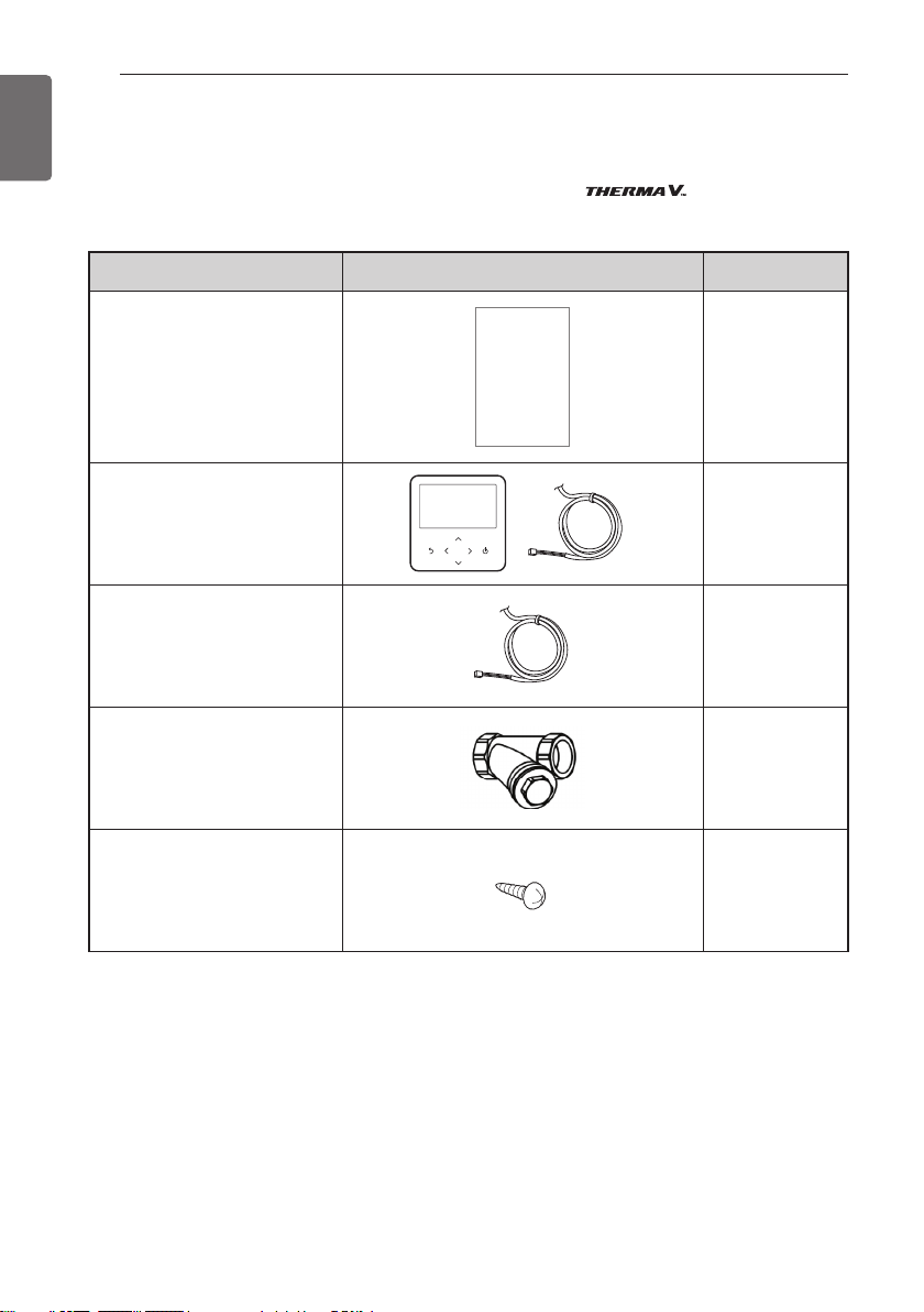
Thank you for choosing LG Electronics Air-to-Water Heat Pump .
Before starting installation, please make it sure that all parts are found inside the product box.
Item Image Quantity
Installation Manual
Remote Controller
/ Cable
Water Tank
Temperature Sensor
Strainer
Screw
1
1
1
1
4
GENERAL INFORMATION
GENERAL INFORMATION
With advanced inverter technology, is suitable for applications like under floor
heating, under floor cooling, and hot water generation. By Interfacing to various accessories user
can customize the range of the application.
In this chapter, general information of is presented to identify the installation
procedure. Before beginning installation, read this chapter carefully and find helpful information
on installation.
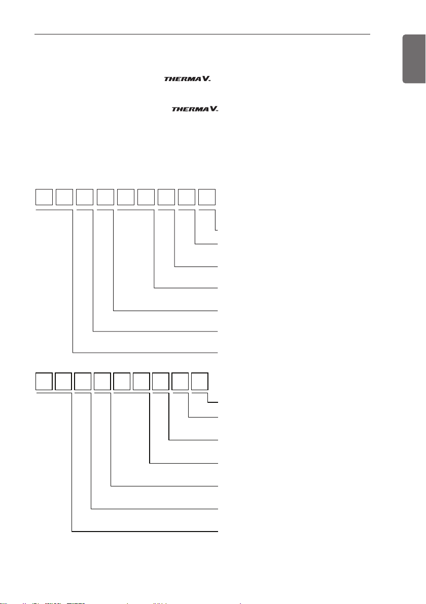
Model Information
Factory Model Name
A HUW 1 6 6 T 3
Series Number
Function
T : High temperature
Electrical ratings
6 : 1 phase 220-240 V~ 50 Hz
Heating Capacity (kW)
16 : 16 kW
Model Type
W : DC Inverter Heat Pump
Classification
U : Outdoor Unit
Air-to-Water-Heat Pump
13
ENGLISH
A H N W 1 6 6 T3
Series Number
Function
T : High temperature
Heater Electrical ratings
6 : 1 phase 220-240 V~ 50 Hz
Heating Capacity (kW)
16 : 16 kW
Model Type
W : Inverter Heat Pump
Classification
N : Indoor Unit
Air-to-Water-Heat Pump
- Additional Information : serial number is refer to the barcode on the product.
- Max allowable pressure High side : 4.2 MPa / Low side : 2.4 MPa
- Refrigerant : R410A, R134a
GENERAL INFORMATION
14
ENGLISH
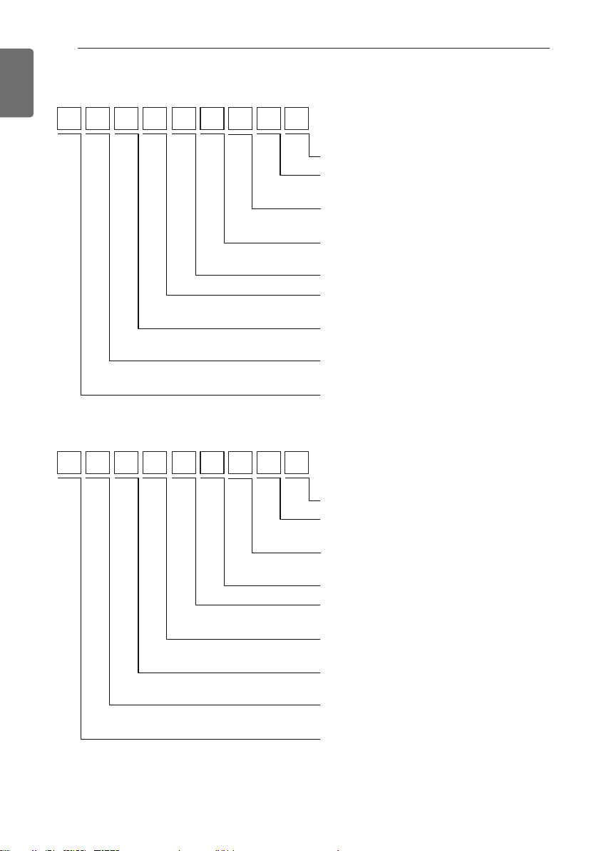
Buyer Model Name
H U 16 1 H A U 3 3
Series Number
Platform (Chassis code)
3 : U3 Chassis
Classification
U : Outdoor Unit
Refrigerant
A : R410A
High Temperature
Electrical ratings
1 : 1Ø, 220-240 V~ 50 Hz
Heating Capacity (kW)
16 : 16 kW
Classification
U : Outdoor Unit
H : Air to Water Heat Pump
H N 16 1 0 H N K 3
Series Number
Platform (Chassis code)
K : K3 Chassis
Classification
N : Indoor Unit
High Temperature
Heater Capacity (kW)
0 : None
Heater Electrical ratings
1 : 1Ø, 220-240 V~ 50 Hz
Heating Capacity (kW)
16 : 16 kW
Classification
N : Indoor Unit
H : Air to Water Heat Pump
- Additional Information : serial number is refer to the barcode on the product.
- Max allowable pressure High side : 4.2 MPa / Low side : 2.4 MPa
- Refrigerant : R410A, R134a
GENERAL INFORMATION
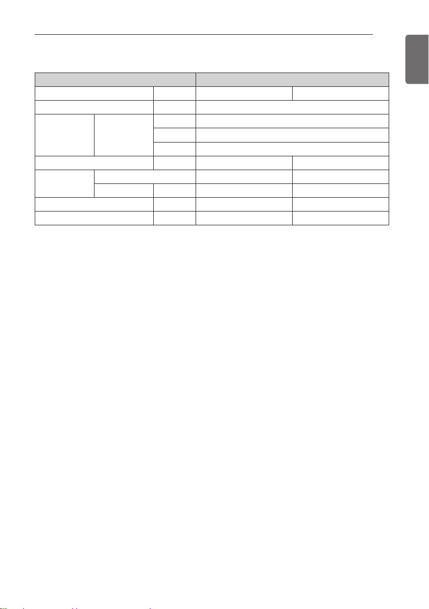
Model name and related information
Type Air-to water Heat Pump (For High Temperature)
Model Unit Indoor Outdoor
Power Supply Ø, V, Hz 1, 220-240, 50
*1
kW
Capacity Heating
Net Weight kg(lbs) 84(185) 89(196)
Refrigerant
Sound Power Level(PWL) dB(A) 63 63
Maximum Running Current A 20.2 18.9
*1 : tested under EN14511
(water temperature 30 °C ’ 35 °C at outdoor ambient temperature 7 °C / 6 °C)
• All appliances were tested at atmospheric pressure.
Amount kg(lbs) 1.8(3.9) 3.8(8.3)
kcal/h 13 760
Btu/h 54 600
Type R134a R410A
16
15
ENGLISH
GENERAL INFORMATION
16
ENGLISH
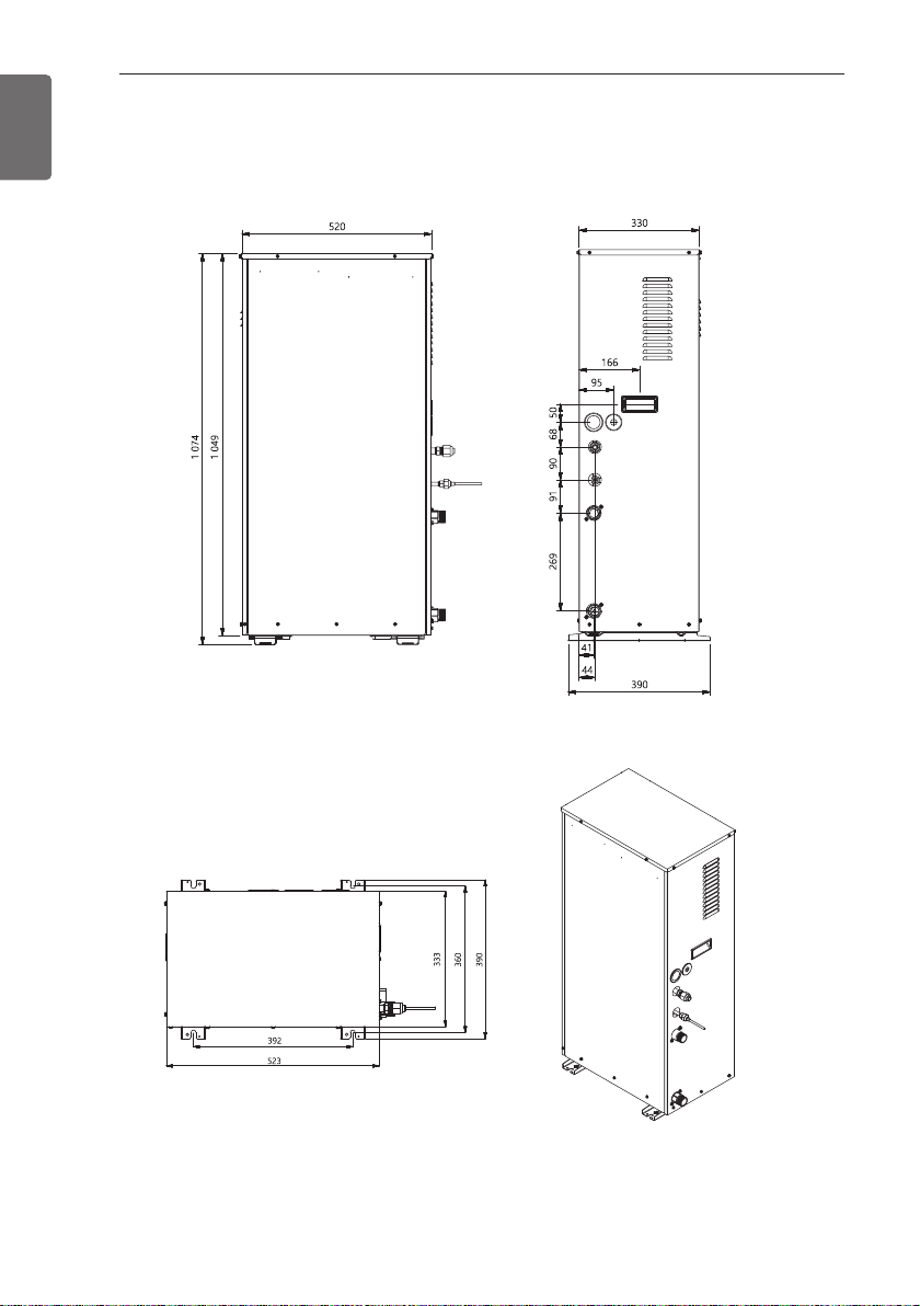
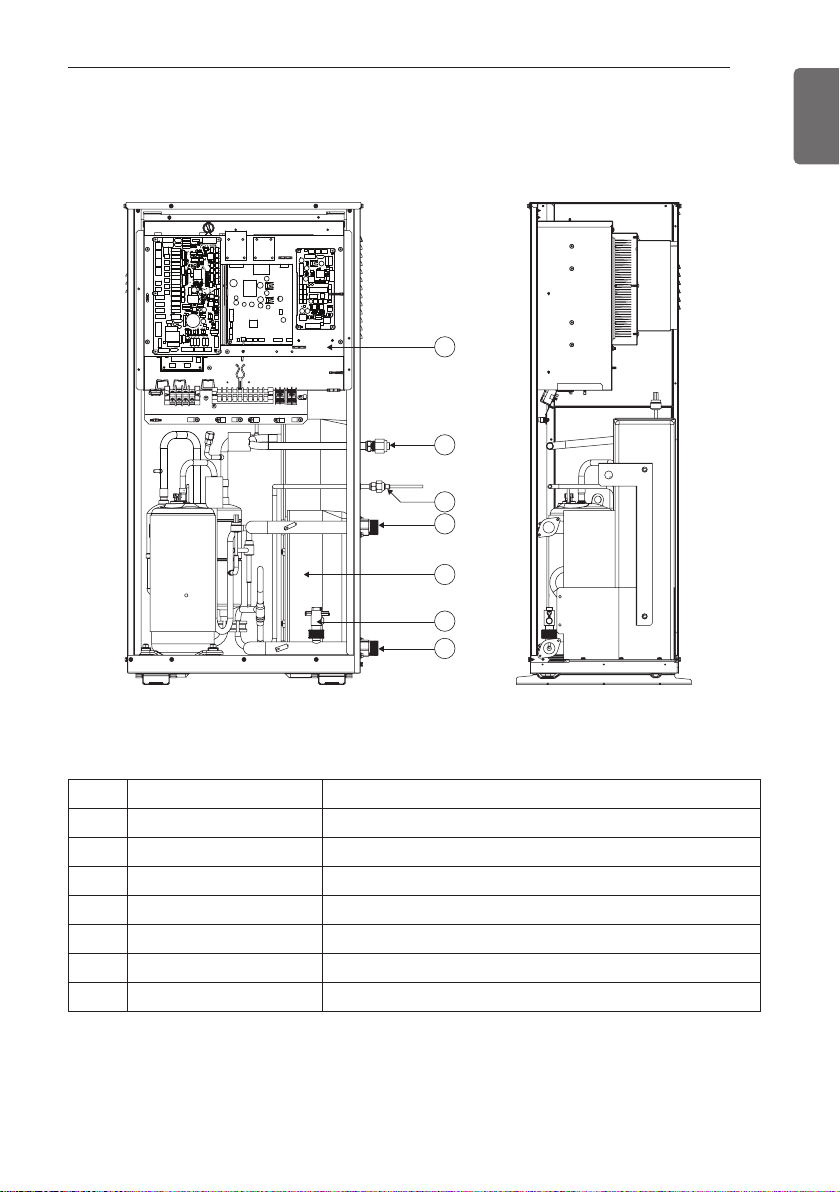
Parts and Dimensions
Indoor unit : External
(unit : mm)
5
4
3
1
7
6
2
Indoor unit : Internal
GENERAL INFORMATION
(unit : mm)
17
ENGLISH
Description
No Name Remark
1 Leaving Water Pipe Male PT 1 inch
2 Entering Water Pipe Male PT 1 inch
3 Refrigerant Pipe Ø 9.52 mm
4 Refrigerant Pipe Ø 15.88 mm
5 Control Box PCB and terminal blocks
6 Flow Switch Minimum operation range at 15 LPM.
7 Plate Heat Exchanger Heat exchange between refrigerant and water
GENERAL INFORMATION
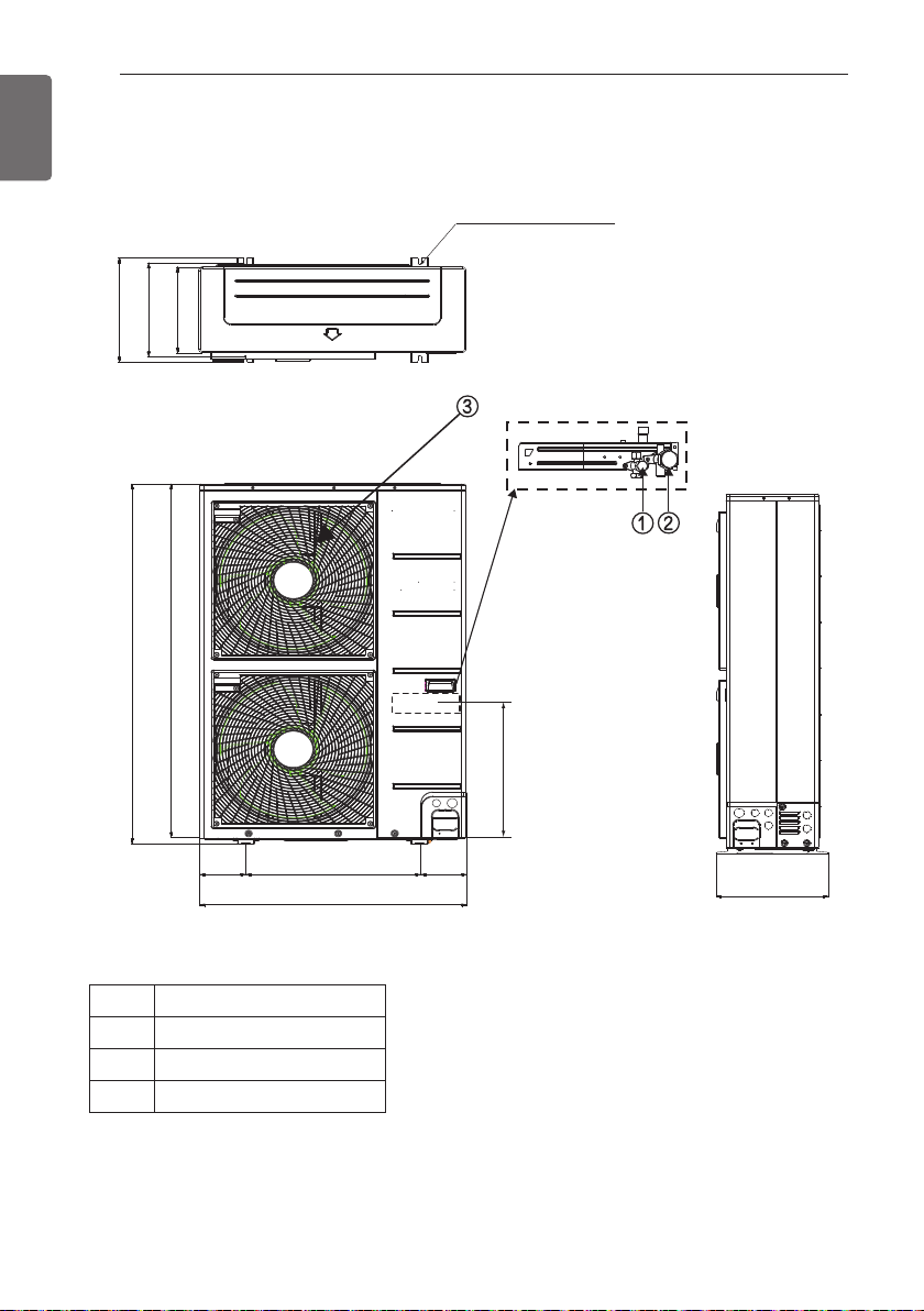
18
ENGLISH
Outdoor unit : External
390
360
330
1 380
1 356
4-holes for anchor bolts
Supporter
Product Heating Capacity :
16 kW
U3 Chassis
(unit : mm)
165 165
Description
No Name
1 Liquid-side Service Valve
2 Gas-side Service Valve
3 Air discharge Grill
620
950
490
390
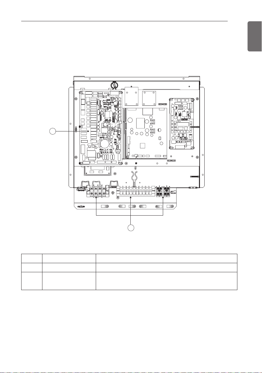
Control Parts
Control Box : Indoor Unit
2
GENERAL INFORMATION
19
ENGLISH
1
Description
No Name Remark
1 Terminal blocks The terminal blocks allow easy connection of field wiring
2 Main PCB
The main PCB(Printed Circuit Board) controls the functioning
of the unit
GENERAL INFORMATION
20
ENGLISH
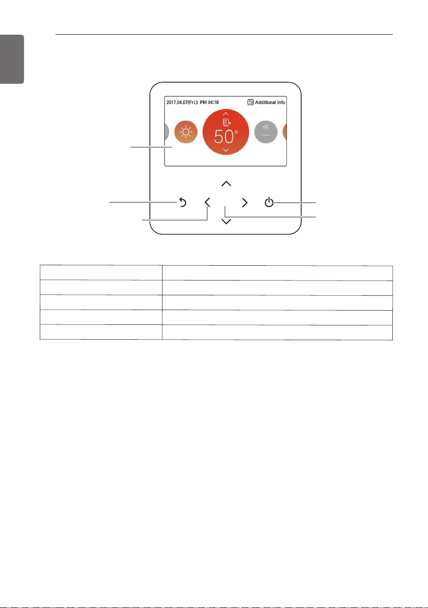
Control Panel
Operation display
window
Back button
Up/Down/Left/Right
button
Operation display window
Back button
Up/down/left/right button
OK button
On/Off button
Wiring Diagram : Indoor Unit
- Refer to the wiring diagram inside the control box.
Circuit Diagram : Indoor Unit
- Refer to the circuit diagram inside the front panel.
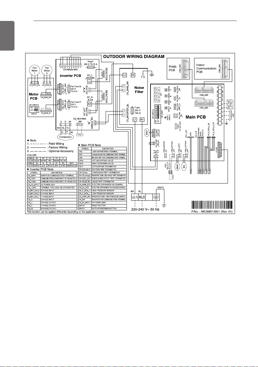
Wiring Diagram : Outdoor Unit
- Refer to the attached wiring diagram in the outdoor unit.
Operation and Settings status display
When you move to the previous stage from the menu’s setting stage
When you change the menu’s setting value
When you save the menu’s setting value
When you turn ON/OFF the AWHP
OK
On/Off button
OK button
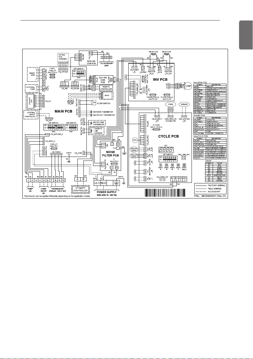
Wiring Diagram
Indoor Unit
GENERAL INFORMATION
21
ENGLISH
GENERAL INFORMATION
22
ENGLISH
Wiring Diagram
Outdoor Unit
GENERAL INFORMATION
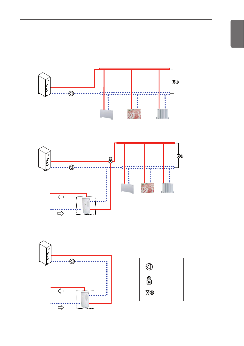
Floor heating loopFan coil unit
Radiator
Floor heating loop
Fan coil unit
Sanitary
water
tank
Hot water
Cold water supply
Radiator
Sanitary
water
tank
Hot water
Cold water supply
Pump
3way valve
Bypass valve
Typical Installation Example
Some installation scenes are presented for example. As these scenes are conceptual figures,
installer should optimize the installation scene according to the installation conditions.
Floor Heating only
Floor Heating + Hot water
23
ENGLISH
Hot water only
GENERAL INFORMATION
24
ENGLISH
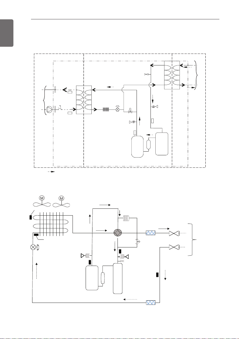
Cycle Diagram
Indoor Unit
Water side
Sanitary
tank
Or
Floor
Heating
Outdoor Unit
Inlet Air Temperat ure
Indoor Unit
Male
PT 1
Male
PT 1
: Heating
Water. Out
Water out
Temperature
sensor
Flow Switch
Water. In
Water in
Temperature
sensor
Ref, Out
port
Charging
s
Inverter
Compressor
Ref, In
Low
Pressure
Sensor
Suction
Temperature
sensor
Accumulator
Ref, In
Ref, Out
Strainer
Electronic
Expansion
Valve
Pressure
Sensor
High
Discharge
Temperature
sensor
Ref, In
Ref, Out
edis A014Redis a431R
Outdoor
Unit
Condensing Tem perature Sensor
Electronic Expansion Valve
High Pressure Sensor
Discharge Temperatu re
Sensor
Invert er
Compressor
4 Way Valve
Suction Temperature sensor
Low Pressure Sensor
Charging Port
Accumulator
Strainer
s
Hot Gas Valve
Liquid Pipe
Temperature
Sensor
Strainer
Ø 15.88
Ø 9.52
INDOOR
UNIT
INSTALLATION
INSTALLATION
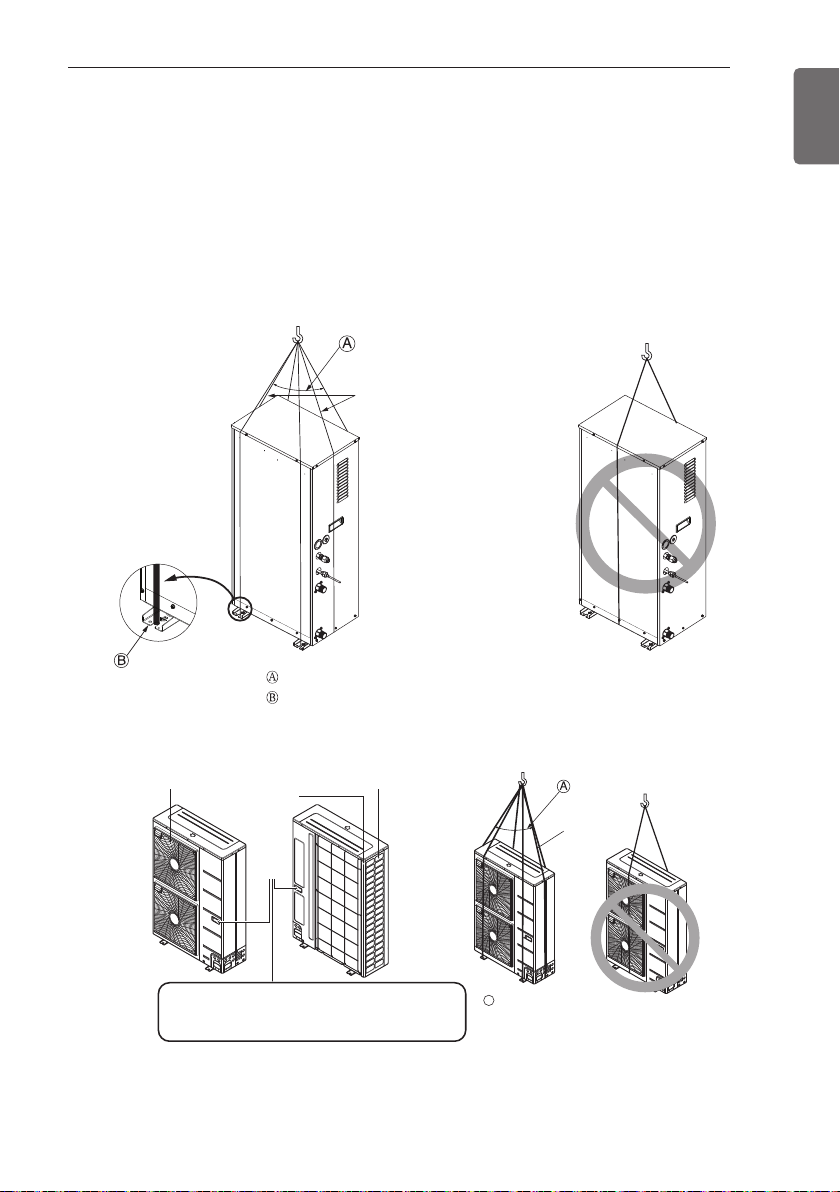
Transporting the Unit
• When carrying the suspended unit, pass the ropes between legs of base panel under the unit.
• Always lift the unit with ropes attached at four points so that impact is not applied to the unit.
• Attach the ropes to the unit at an angle Ⓐ of 40° or less.
• Use only accessories and parts which are of the designated specification when installing.
Indoor Unit
Sub line
25
ENGLISH
Outdoor Unit
Air outlet grille Intake hole
Always hold the unit by the corners, as holding
it by the side intake holes on the casing may
cause them to deform.
Corner
Handle
40º or less
Line supporter
A
40° or less
Sub line

INSTALLATION
26
ENGLISH
CAUTION
!
Be very careful while carrying the product.
• Do not have only one person carry product if it is more than 20 kg.
• PP bands are used to pack some products. Do not use them as a mean for transportation
because they are dangerous.
• Do not touch heat exchanger fins with your bare hands. Otherwise you may get a cut on
your hands.
• Tear plastic packaging bag and scrap it so that children cannot play with it. Otherwise
plastic packaging bag may suffocate children to death.
• When carrying in Unit, be sure to support it at four points. Carrying in and lifting with
3-point support may make Outdoor Unit unstable, resulting in a fall.
• Use 2 belts of at least 8 m long.
• Place extra cloth or boards in the locations where the casing comes in contact with the
sling to prevent damage.
• Hoist the unit making sure it is being lifted at its center of gravity.
Selection of the best location
Indoor
Select space for installing Indoor Unit, which will meet the following conditions:
- The place where the unit shall be installed inside.
- The place shall easily bear a load exceeding four times of the unit weight.
- The place where the unit shall be leveled.
- The place shall allow easy water drainage.
- The place where the unit shall be connected to the outdoor unit.
- The place where the unit is not affected by an electrical noise.
- The place where there should not be any heat source or steam near the unit.
Outdoor
Select space for installing outdoor unit, which will meet the following conditions:
- No direct thermal radiation from other heat sources
- No possibility of annoying neighbors by noise from unit
- No exposition to strong wind
- With strength which bears weight of unit
- Note that drain flows out of unit when heating
- With space for air passage and service work shown next
- Because of the possibility of fire, do not install unit to the space where generation, inflow,
stagnation, and leakage of combustible gas is expected.
- Avoid unit installation in a place where acidic solution and spray (sulfur) are often used.
- Do not use unit under any special environment where oil, steam and sulfuric gas exist.
- It is recommended to fence round the outdoor unit in order to prevent any person or animal
from accessing the outdoor unit.
- If installation site is area of heavy snowfall, then the following directions should be observed.
- Make the foundation as high as possible.
- Fit a snow protection hood.

INSTALLATION
27
Select installation location considering following conditions to avoid bad condition when
additionally performing defrost operation.
- Install the outdoor unit at a place well ventilated and having a lot of sunshine in case of installing
the product at a place with a high humidity in winter (near beach, coast, lake, etc).
(Ex) Rooftop where sunshine always shines.
- Performance of heating will be reduced and preheat time of the indoor unit may be lengthened
in case of installing the outdoor unit in winter at following location:
- Shade position with a narrow space
- Location with much moisture in neighboring floor.
- Location with much humidity around.
- Location where ventilation is good.
It is recommended to install the outdoor unit at a place with a lot of sunshine as possible as.
- Location where water gathers since the floor is not even.
When installing the outdoor unit in a place that is constantly exposed to a strong wind like
a coast or on a high story of a building, secure a normal fan operation by using a duct or a
wind shield.
- Install the unit so that its discharge port faces to the wall of the building.
Keep a distance 500 mm or more between the unit and the wall surface.
- Supposing the wind direction during the operation season of the air conditioner, install the unit
so that the discharge port is set at right angle to the wind direction.
Strong
wind
ENGLISH
Air inlet grille
More
500
Blown
air
Strong
wind
INSTALLATION
400520300
Service space
(front side)
330
600
Piping space
(front side)
Service space
(left side)
28
ENGLISH
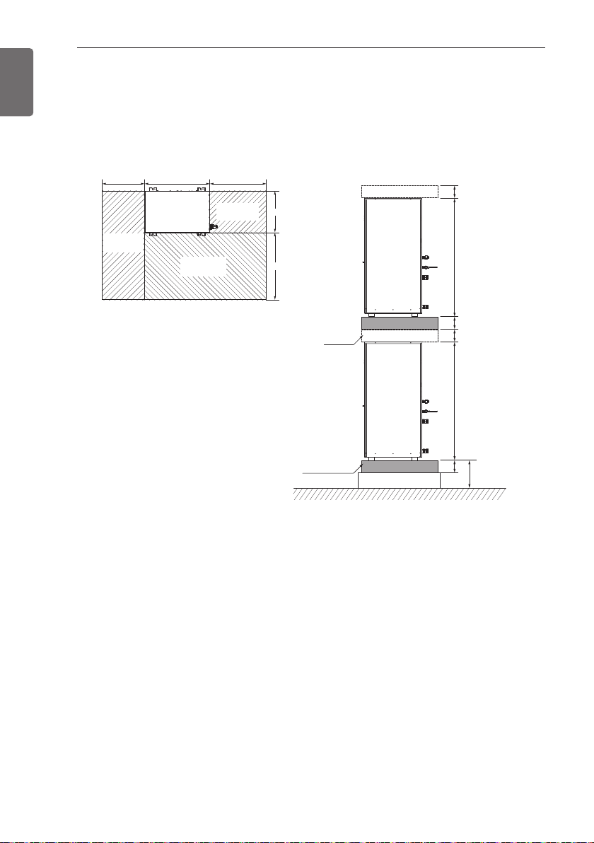
Installation Space
Indoor Unit
- The following values are the least space for installation. If any service area is needed for service
according to field circumstance, obtain enough service space.
- The unit of values is mm.
(Unit: mm)
100100100100
1 0741 074
(Unit: mm)
space
H-Beam supporter
200
Outdoor Unit
- The following values are the least space for installation.
If any service area is needed for service according to field circumstance, obtain enough service
space.
- The unit of values is mm.
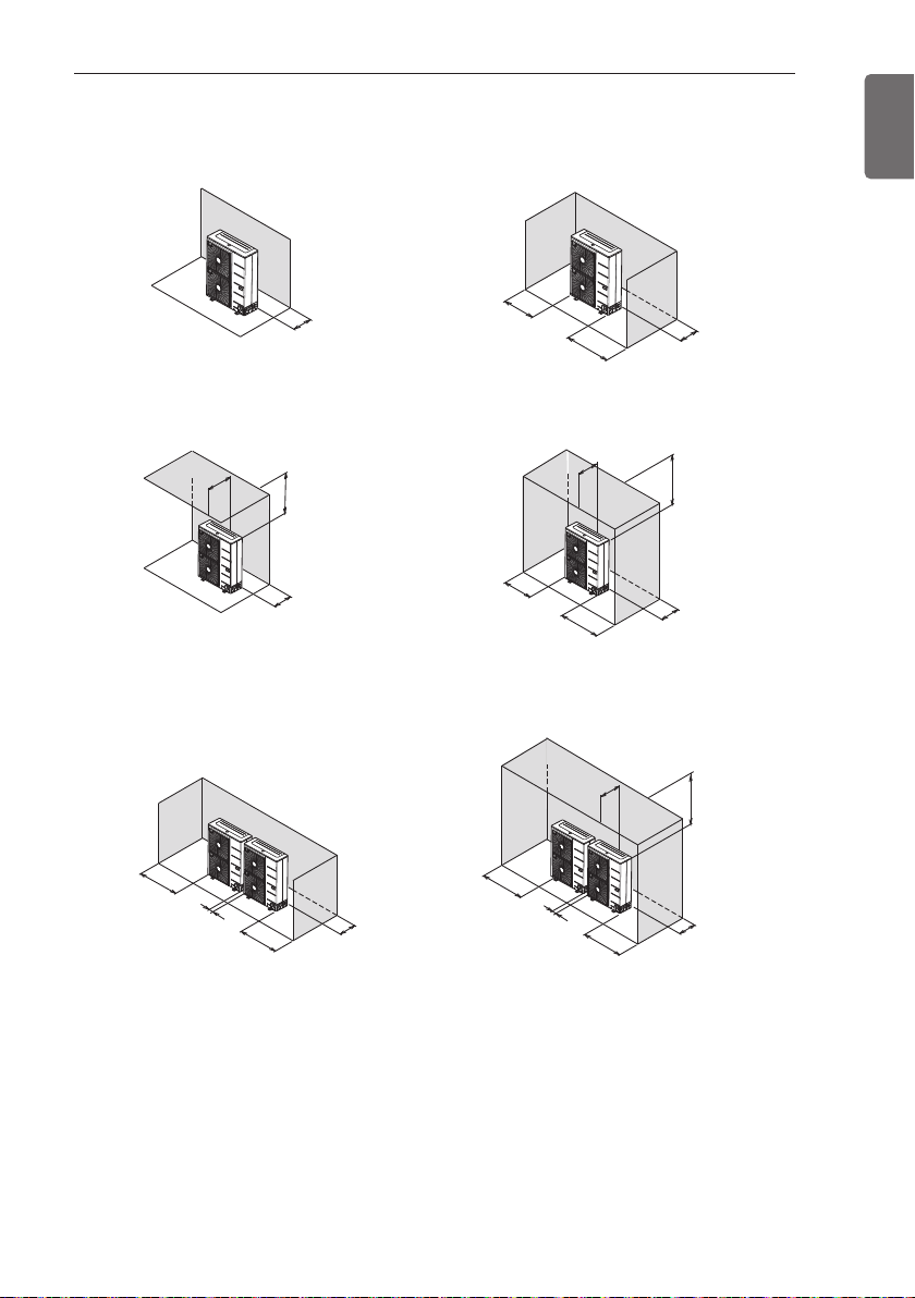
In case of obstacles on the suction side
100 or
more
100 or
more
100 or
100 or
more
more
500 or less
more
1 000 or
100 or
more
more
1 000 or
150 or
more
150 or
150 or
more
more
500 or less500 or less500 or less500 or less
[Unit:mm]
500 or less500 or less500 or less500 or less
500 or less
more
1 000 or
300 or
more
100 or
more
200 or
more
1 000 or
more
300 or
more
100 or
more
1 000 or
more
200 or
more
[Unit:mm]
Stand alone installation
Collective installation
INSTALLATION
29
ENGLISH
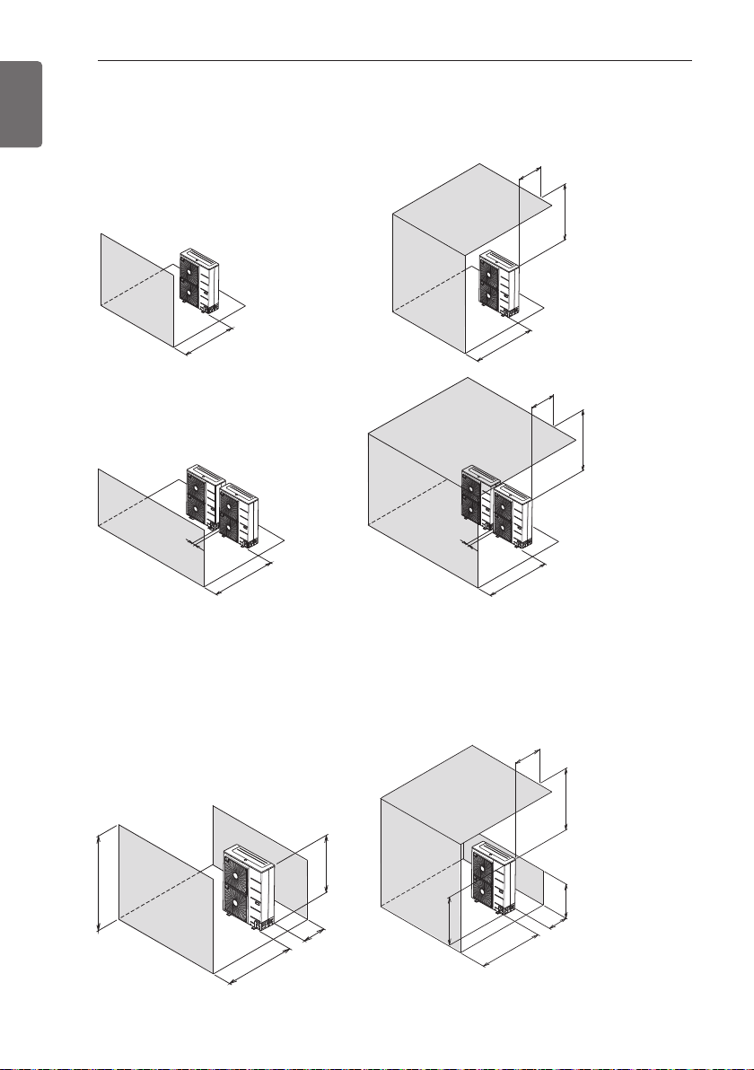
INSTALLATION
500 or more
500 or less500 or less500 or less
more
1 000 or
500 or more
1 000 or more
500 or less
1 000 or more
1 000 or more
100 or
more
100 or
more
[Unit:mm]
500 or less
H
L
L > HL > H
100 or
more
500 or
more
500 or less
more
1 000 or
L
H
250 or
more
1 000 or
more
[Unit:mm]
30
ENGLISH
In case of obstacles on the discharge side
Stand alone installation
Collective installation
In case of obstacles on the suction and the discharge side
Ú Obstacle height of discharge side is higher than the unit
Stand alone installation
 Loading...