

LG HU161H INSTALLATION MANUAL

www.lg.com
INSTALLATION MANUAL
AIR
CONDITIONER
Please read this installation manual completely before installing the product.
Installation work must be performed in accordance with the national wiring standards
by authorized personnel only.
Please retain this installation manual for future reference after reading it thoroughly.
Air-to-Water Heat Pump (For High Temperature)
[
Representative] LG Electronics Inc. EU Representative : LG Electronics European Shared
Service Center B.V. Krijgsman 1, 1186 DM Amstelveen, The Netherlands
[Manufacturer] LG Electronics Inc. Changwon 2nd factory 84, Wanam-ro, Seongsan-
gu, Changwon-si, Gyeongsangnam-do, KOREA
For more information, Refer to the CD or LG Web site (www.lg.com).
P/NO : MFL67212813
ENGLISH
FRANÇAIS
ΕΛΛΗΝΙΚΆ

2
AWHP
Installation Manual
TABLE OF CONTENTS
1. SAFETY PRECAUTIONS..............................................................................................................3
2. INSTALLATION PARTS ................................................................................................................8
3. GENERAL INFORMATION ..........................................................................................................9
4. INSTALLATION...........................................................................................................................10
TRANSPORTING THE UNIT ......................................................................................................10
SELECTION OF THE BEST LOCATION.....................................................................................11
INSTALLATION SPACE ..............................................................................................................12
COLLECTIVE / CONTINUOUS INSTALLATION FOR ROOF TOP USE....................................16
FOUNDATION FOR INSTALLATION ..........................................................................................17
WATER PIPING AND WATER CIRCUIT CONNECTION ............................................................18
SANITARY WATER TANK AND SANITARY WATER TANK KIT .................................................22
INSTALLATION SCENES ...........................................................................................................23
REFRIGERANT PIPING .............................................................................................................25
FLARE SHAPE AND FLARE NUT TIGHTENING TORQUE.......................................................26
OPENING SHUTOFF VALVE......................................................................................................26
CLOSING SHUTOFF VALVE ......................................................................................................26
CONNECTING THE PIPES TO THE OUTDOOR UNIT..............................................................27
CAUTIONS FOR HANDLING SERVICE VALVE.........................................................................28
SELECTION OF REFRIGERANT PIPING..................................................................................29
THE AMOUNT OF REFRIGERANT............................................................................................29
LEAK TEST AND VACUUM DRYING .........................................................................................30
HOW TO CONNECT WIRINGS..................................................................................................33
CONNECTION METHOD OF THE CONNECTING CABLE (EXAMPLE)...................................34
CONNECTING CABLES.............................................................................................................38
COMMUNICATION AND POWER CABLE..................................................................................39
WIRING OF MAIN POWER SUPPLY AND EQUIPMENT CAPACITY ........................................40
5. ACCESSORIES INSTALLATION................................................................................................41
LOCATION OF ACCESSORIES AND EXTERNAL PARTS CONNECTION ...............................41
MAIN PUMP CONNECTION.......................................................................................................44
WATER TANK TEMPERATURE SENSOR CONNECTION ........................................................44
THERMOSTAT............................................................................................................................45
REMOTE TEMPERATURE SENSOR.........................................................................................48
3WAY VALVE ..............................................................................................................................49
DRY CONTACT...........................................................................................................................51
6. SYSTEM SET-UP........................................................................................................................52
DIP SWITCH SETTING...............................................................................................................52
INSTALLER SETTING ................................................................................................................59
7. TEST RUN...................................................................................................................................67
CHECKS BEFORE TEST RUN...................................................................................................68
TEST RUN PROCEDURE ..........................................................................................................68
CAUTION BEFORE OPERATION TEST ....................................................................................69
OPERATION TEST OF WATER PIPE ........................................................................................68
TROUBLESHOOTING ................................................................................................................69
Safety Precautions
Installation Manual 3
ENGLISH
1. Safety Precautions
To prevent injury to the user or other people and property damage, the following instructions must be followed.
n Be sure to read before installing the unit.
n Be sure to observe the cautions specified here as they include important items related
to safety.
n Incorrect operation due to ignoring instruction will cause harm or damage. The serious-
ness is classified by the following indications.
n Meanings of symbols used in this manual are as shown below.
This symbol indicates the possibility of death or serious injury.
This symbol indicates the possibility of injury or damage to properties only.
n Installation
Be sure not to do.
Be sure to follow the instruction.
Do not use a defective
or underrated circuit
breaker. Use this appliance on a dedicated
circuit.
• There is risk of fire or
electric shock.
For electrical work,
contact the dealer,
seller, a qualified electrician, or an Authorized Service Center.
• There is risk of fire or
electric shock.
Always ground the unit.
• There is risk of fire or
electric shock.
Install the panel and
the cover of control
box securely.
• There is risk of fire or
electric shock.
Always install a dedicated circuit and
breaker.
• Improper wiring or installation may cause fire or
electric shock.
Use the correctly rated
breaker or fuse.
• There is risk of fire or
electric.

Safety Precautions
4
The refrigerant of this unit
is R134a and the unit is
connected to the outdoor
unit where R410A refrigerant is used.
• The installation tool such
as manifold gauge
should comply with
R410A.
For installation, always
contact the dealer or an
Authorized Service
Center.
• There is risk of fire, electric shock, explosion, or
injury.
Do not install the unit
on a defective installation stand.
• It may cause injury, accident, or damage to the
unit.
Be sure the installation
area does not deteriorate with age.
• If the base collapses, the
unit could fall with it,
causing property damage, unit failure, and personal injury.
Do not install the water
pipe system as Open
loop type.
• It may cause failure of
unit.
Do not install the Indoor Unit outside.
• It may cause damage to
the unit.
Use a vacuum pump or inert (nitrogen) gas when doing leakage test or purging air. Do not compress air or oxygen and do not use flammable gases.
• There is the risk of death, injury, fire or explosion.
Do not modify or extend the power cable.
• There is risk of fire or
electric shock.
Do not install, remove,
or reinstall the unit by
yourself (customer).
• There is risk of fire, electric shock, explosion, or
injury.
For antifreeze, always
contact the dealer or an
authorized service center.
• Almost the antifreeze is a
toxic product.

Safety Precautions
Installation Manual 5
ENGLISH
Take care to ensure
that power cable could
not be pulled out or
damaged during operation.
• There is risk of fire or
electric shock.
Do not place anything
on the power cable.
• There is risk of fire or
electric shock.
Do not plug or unplug
the power supply plug
during operation.
• There is risk of fire or
electric shock.
Do not touch (operate)
the unit with wet hands.
• There is risk of fire or
electric shock.
Do not place a heater
or other appliances
near the power cable.
• There is risk of fire or
electric shock.
Do not allow water to
run into electric parts.
• There is risk of fire, failure of the unit, or electric
shock.
Do not store or use
flammable gas or combustibles near the unit.
• There is risk of fire or
failure of unit.
Do not use the unit in a
tightly closed space for
a long time.
• It may cause damage to
the unit.
When flammable gas
leaks, turn off the gas
and open a window for
ventilation before turning the unit on.
• There is risk of explosion
or fire.
n Operation
If strange sounds, or
small or smoke comes
from unit, turn the
breaker off or disconnect the power supply
cable.
• There is risk of electric
shock or fire.
Stop operation and
close the window in
storm or hurricane. If
possible, remove the
unit from the window
before the hurricane arrives.
• There is risk of property
damage, failure of unit,
or electric shock.
Do not open the front
cover of the unit while
operation. (Do not
touch the electrostatic
filter, if the unit is so
equipped.)
• There is risk of physical
injury, electric shock, or
unit failure.
Safety Precautions
6
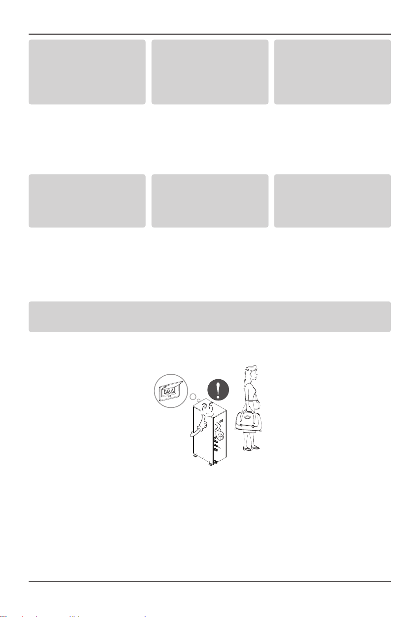
If the unit is not used for long time, we strongly recommend not to switch off
the power supply to the unit.
• There is risk of water freezing.
When the unit is
soaked (flooded or submerged), contact an
Authorized Service
Center.
• There is risk of fire or
electric shock.
Be cautious that water
could not be poured to
the unit directly.
• There is risk of fire, electric shock, or unit damage.
Ventilate the unit from
time to time when operating it together with a
stove, etc.
• There is risk of fire or
electric shock.
Turn the main power off
when cleaning or maintaining the unit.
• There is risk of electric
shock.
Take care to ensure
that nobody could step
on or fall onto the unit.
• This could result in personal injury and unit
damage.
For installation, always
contact the dealer or an
Authorized Service
Center.
• There is risk of fire, electric shock, explosion, or
injury.
Safety Precautions
Installation Manual 7
ENGLISH
n Installation
Always check for gas
(refrigerant) leakage
after installation or repair of unit.
• Low refrigerant levels
may cause failure of unit.
Keep level even when
installing the unit.
• To avoid vibration or
water leakage.
Use two or more people
to lift and transport the
unit.
• Avoid personal injury.
Do not use the unit for
special purposes, such
as preserving foods,
works of art, etc.
• There is risk of damage
or loss of property.
Use a soft cloth to
clean.
Do not use harsh detergents, solvents, etc.
• There is risk of fire, electric shock, or damage to
the plastic parts of the
unit.
Do not step on or put
anything on the unit.
• There is risk of personal
injury and failure of unit.
Use a firm stool or ladder when cleaning or maintaining the unit.
• Be careful and avoid personal injury.
n Operation
Installation Parts
8
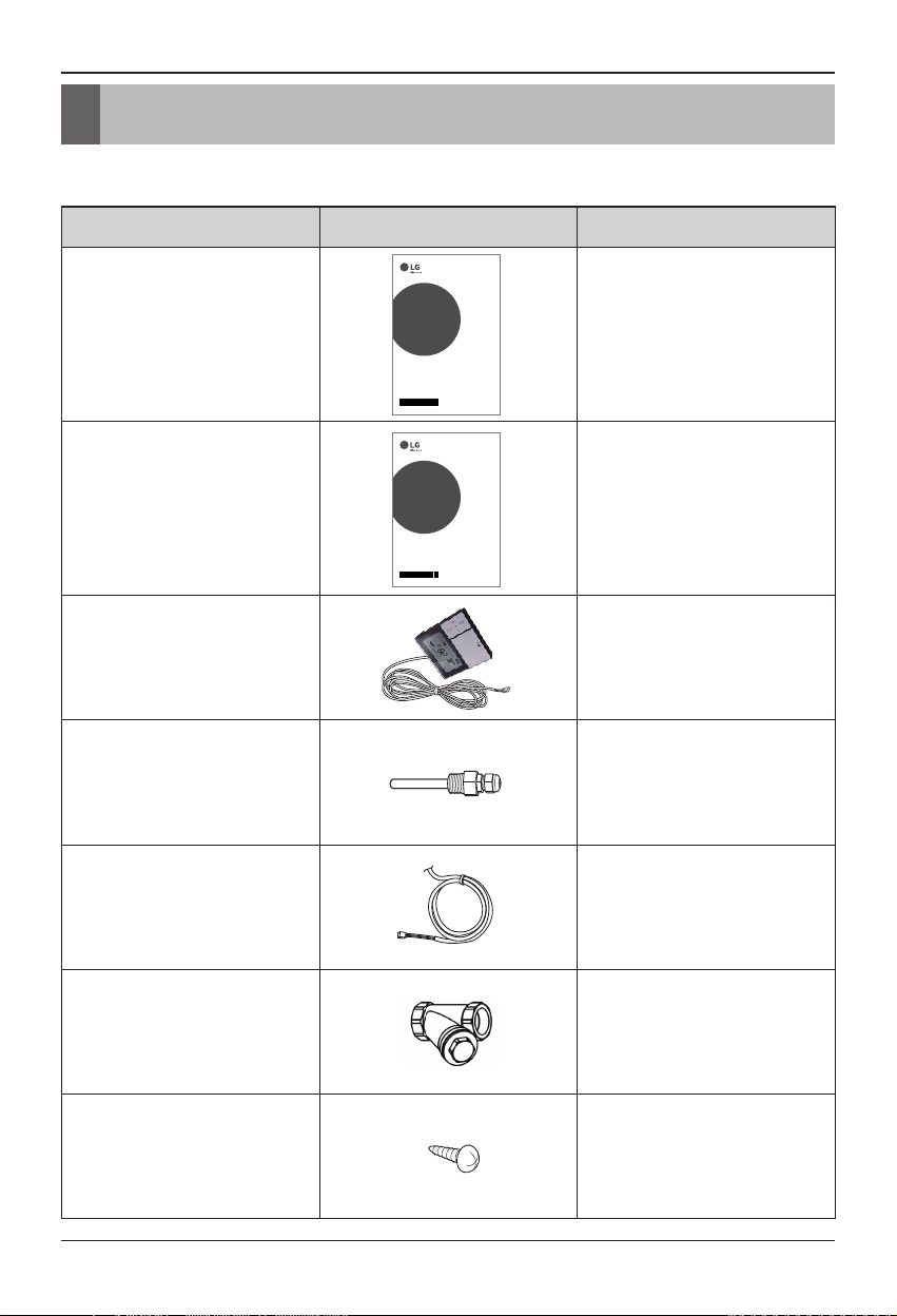
2. Installation Parts
Before starting installation, please make it sure that all parts are found inside the unit box.
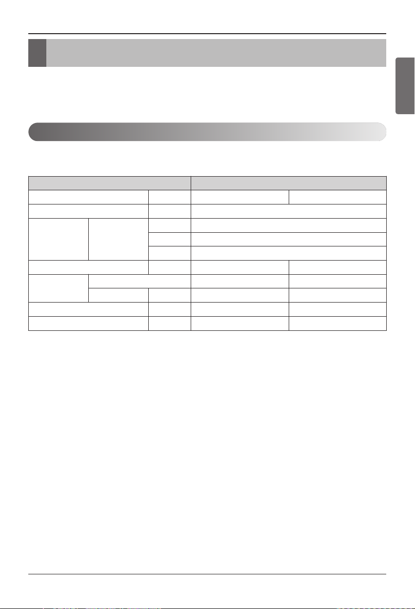
Item Image Quantity
Installation Manual
1
Owner's Manual 1
Remote Controller
/ Cable
1
Sensor Holder 1
Water Tank
Temperature Sensor
1
Strainer
1
Screw
4
INSTALLATION MANUAL
AIR
CONDITIONER
Please read this installation manual completely before installing the product.
Installation work must be performed in accordance with the national wiring standards
by authorized personnel only.
Please retain this installation manual for future reference after reading it thoroughly.
Air-to-Water Heat Pump (For High Temperature)
Representative] LG Electronics Inc. EU Representative : LG Electronics European Shared
[
Service Center B.V. Krijgsman 1, 1186 DM Amstelveen, The Netherlands
[Manufacturer] LG Electronics Inc. Changwon 2nd factory 84, Wanam-ro, Seongsan-
gu, Changwon-si, Gyeongsangnam-do, KOREA
For more information, Refer to the CD or LG Web site (www.lg.com).
P/NO : MFL67212813
OWNER’S MANUAL
AIR
CONDITIONER
Please read this manual carefully before operating
your set and retain it for future reference.
Air-to-Water Heat Pump (For High Temperature)
[Representative] LG Electronics Inc. EU Representative :
LG Electronics European Shared Service Center B.V.
Krijgsman 1, 1186 DM Amstelveen, The Netherlands
[Manufacturer] LG Electronics Inc. Changwon 2nd factory 84, Wanam-ro,
Seongsan-gu, Changwon-si, Gyeongsangnam-do, KOREA
For more information, Refer to the CD or LG Web site (www.lg.com).
P/NO : MFL67212706
www.lg.com
www.lg.com
General Information
Installation Manual 9
ENGLISH
3. General Information
Model Information
With advanced inverter technology, Air-to water Heat Pump (For High Temperature) is suitable
for applications like under floor heating, and hot water generation. By Interfacing to various accessories user can customize the range of the application.
Model name and related information
*1 : Tested under Eurovent Heating condition
(water temperature 55℃(131℉) → 65℃(149℉) at outdoor ambient temperature
7℃(44℉) / 6℃(42℉))
Type
Air-to water Heat Pump (For High Temperature)
Model Unit AHNW166T0 (Indoor) AHUW166T0 (Outdoor)
Power Supply Ø, V, Hz 1, 220-240, 50
Capacity Heating
kW 16
kcal/h
13,760
Btu/h 54,600
Net Weight kg(lbs) 88(194) 98(216)
Refrigerant
Type R134a R410A
Amount kg(lbs) 2.3(5) 3.5(7.7)
Noise Level dB 43 53
Maximum Running Current A 20 19
Installation
10
4. Installation
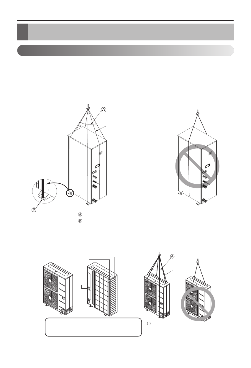
Transporting the Unit
• When carrying the suspended unit, pass the ropes between legs of base panel under the unit.
• Always lift the unit with ropes attached at four points so that impact is not applied to the unit.
• Attach the ropes to the unit at an angle Ⓐ of 40° or less.
• Use only accessories and parts which are of the designated specification when installing.
1) Indoor Unit
2) Outdoor Unit
Sub line
Air outlet grille Intake hole
Always hold the unit by the corners, as holding
it by the side intake holes on the casing may
cause them to deform.
Corner
Handle
40º or less
Line supporter
A
40° or less
Sub line

Installation
Installation Manual 11
ENGLISH
Selection of the best location
1) Indoor
1. Select space for installing Indoor Unit, which will meet the following conditions:
• The place where the unit shall be installed inside.
• The place shall easily bear a load exceeding four times of the unit weight.
• The place where the unit shall be leveled.
• The place shall allow easy water drainage.
• The place where the unit shall be connected to the outdoor unit.
• The place where the unit is not affected by an electrical noise.
• The place where there should not be any heat source or steam near the unit.
2) Outdoor
1. Select space for installing outdoor unit, which will meet the following conditions:
• No direct thermal radiation from other heat sources
• No possibility of annoying neighbors by noise from unit
• No exposition to strong wind
• With strength which bears weight of unit
• Note that drain flows out of unit when heating
• With space for air passage and service work shown next
• Because of the possibility of fire, do not install unit to the space where generation, inflow, stagnation, and leakage of combustible gas is expected.
• Avoid unit installation in a place where acidic solution and spray (sulfur) are often used.
• Do not use unit under any special environment where oil, steam and sulfuric gas exist.
• It is recommended to fence round the outdoor unit in order to prevent any person or animal
from accessing the outdoor unit.
• If installation site is area of heavy snowfall, then the following directions should be observed.
- Make the foundation as high as possible.
- Fit a snow protection hood.
2. Select installation location considering following conditions to avoid bad condition when additionally performing defrost operation.
• Install the outdoor unit at a place well ventilated and having a lot of sunshine in case of installing the product at a place with a high humidity in winter (near beach, coast, lake, etc).
(Ex) Rooftop where sunshine always shines.
• Performance of heating will be reduced and preheat time of the indoor unit may be lengthened
in case of installing the outdoor unit in winter at following location:
- Shade position with a narrow space
- Location with much moisture in neighboring floor.
- Location with much humidity around.
- Location where ventilation is good.
It is recommended to install the outdoor unit at a place with a lot of sunshine as possible as.
- Location where water gathers since the floor is not even.
CAUTION
Be very careful while carrying the unit.
- Do not have only one person carry the unit if it is more than 20 kg (44.1 lbs).
- PP bands are used to pack some products. Do not use them as a mean for transportation because
they are dangerous.
- Tear plastic packaging bag and scrap it so that children cannot play with it. Otherwise plastic packaging bag may suffocate children to death.
- When carrying the unit, be sure to support it at 4-points. Carrying and lifting the unit with 3-point
support may make it unstable, resulting in a fall.
Installation
12
Installation Space
1) Indoor Unit
• The following values are the least space for installation. If any service area is needed for service
according to field circumstance, obtain enough service space.
• The unit of values is mm.
400520300
Service space
(front side)
330
600
Piping space
(front side)
Service space
(left side)
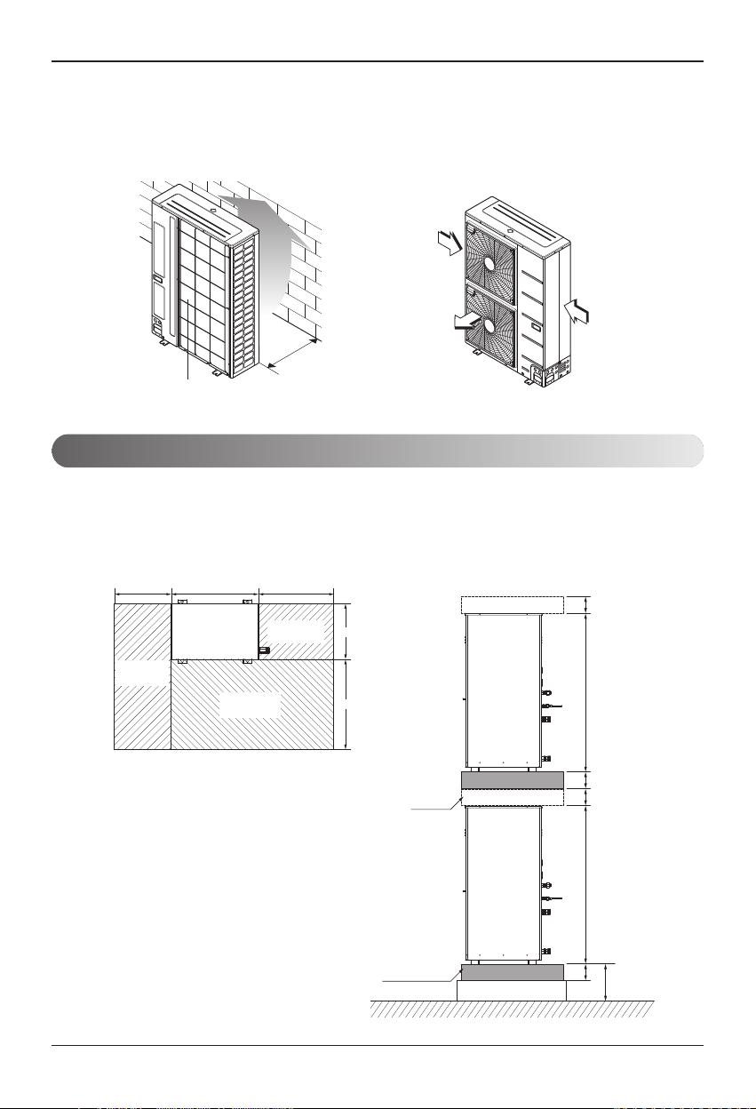
3. When installing the outdoor unit in a place that is constantly exposed to a strong wind like a coast
or on a high story of a building, secure a normal fan operation by using a duct or a wind shield.
• Install the unit so that its discharge port faces to the wall of the building.
Keep a distance 500mm or more between the unit and the wall surface.
• Supposing the wind direction during the operation season of the air conditioner, install the unit
so that the discharge port is set at right angle to the wind direction.
Strong
wind
Strong
wind
Blown
500
air
Air inlet grille
(Unit: mm)
space
H-Beam supporter
(Unit: mm)
100100100100
10801080
200
Installation
Installation Manual 13
ENGLISH
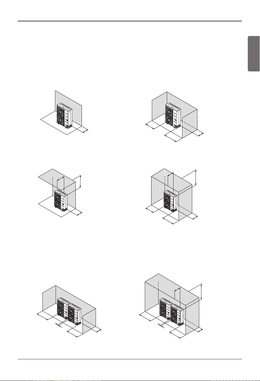
n In case of obstacles on the suction side
1. Stand alone installation
2. Collective installation
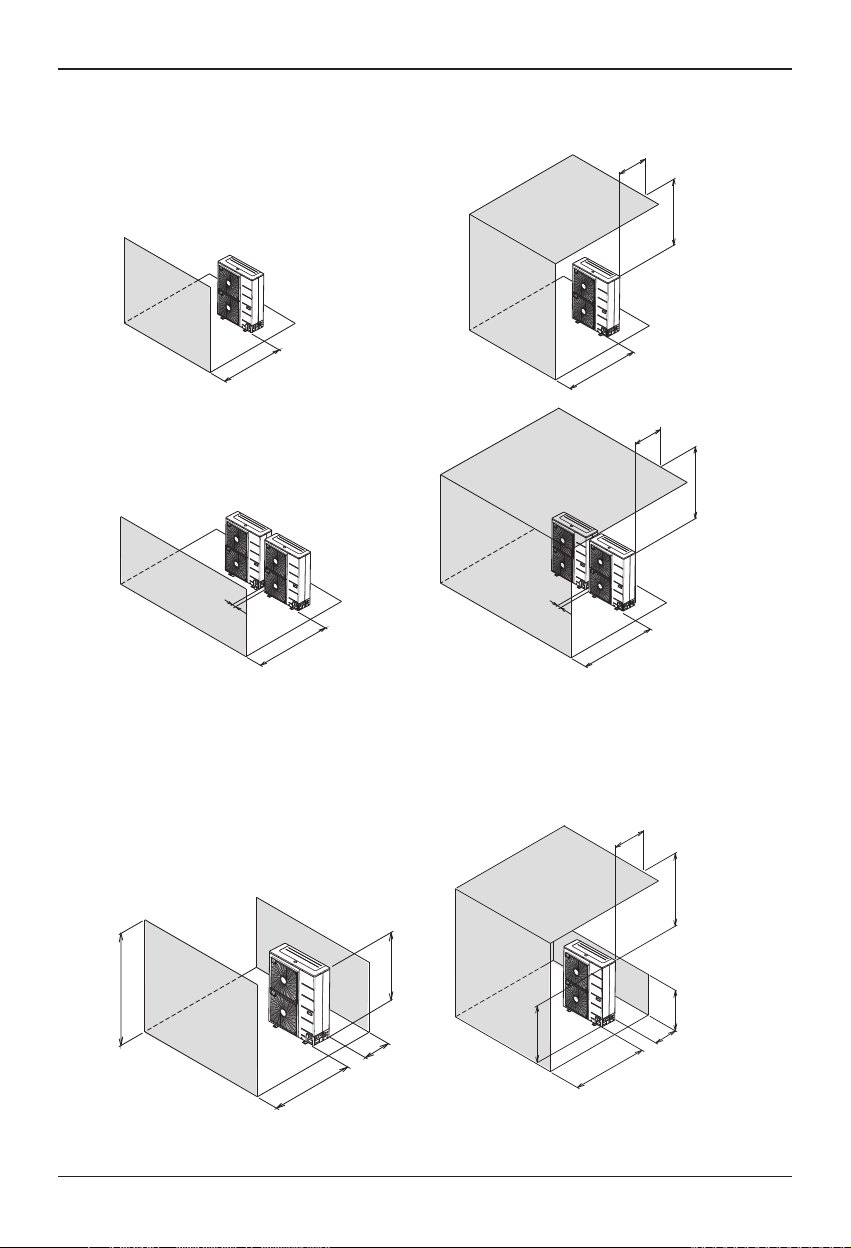
2) Outdoor Unit
• The following values are the least space for installation.
If any service area is needed for service according to field circumstance, obtain enough service
space.
• The unit of values is mm.
100 or
more
100 or
more
100 or
more
100 or
more
500 or less
1000 or
100 or
more
1000 or
more
100 or
more
200 or
more
more
300 or
more
150 or
more
1000 or
more
150 or
more
100 or
more
500 or less
500 or less
200 or
more
150 or
more
300 or
more
more
1000 or
[Unit:mm]
more
1000 or
[Unit:mm]
Installation
14
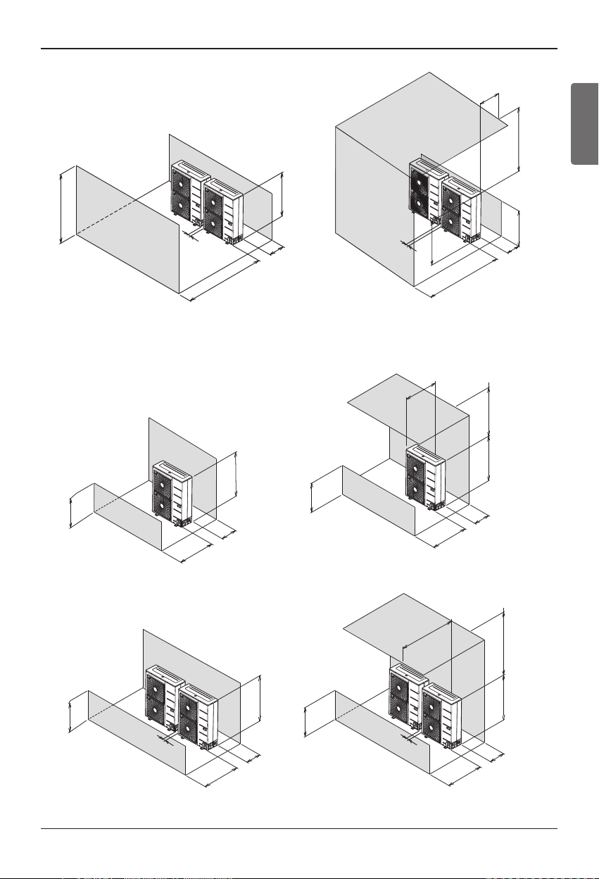
n In case of obstacles on the discharge side
1. Stand alone installation
n In case of obstacles on the suction and the discharge side
Ú Obstacle height of discharge side is higher than the unit
1. Stand alone installation
2. Collective installation
H
L
L > HL > H
100 or
more
500 or
more
500 or less
more
1000 or
L
H
250 or
more
1000 or
more
[Unit:mm]
500 or more
500 or less
more
1000 or
500 or more
1000 or more
500 or less
1000 or more
1000 or more
100 or
more
100 or
more
[Unit:mm]
Installation
Installation Manual 15
ENGLISH
2. Collective installation
2. Collective installation
Ú Obstacle height of discharge side is lower than the unit
1. Stand alone installation
L ≤ H L ≤ H
H
L
300 or
more
1500 or
more
500 or less
more
1000 or
H
L
300 or
more
1500 or
more
100 or more
100 or more
[Unit:mm]
L ≤ H L ≤ H
H
L
100 or
more
500 or
more
500 or less
more
1000 or
H
L
300 or
more
1000 or
more
L > H L > H
L
H
300 or
more
1000 or
more
500 or less
more
1000 or
L
H
300 or
more
1250 or more
5
100 or more
100 or more
[Unit:mm]
Installation
16
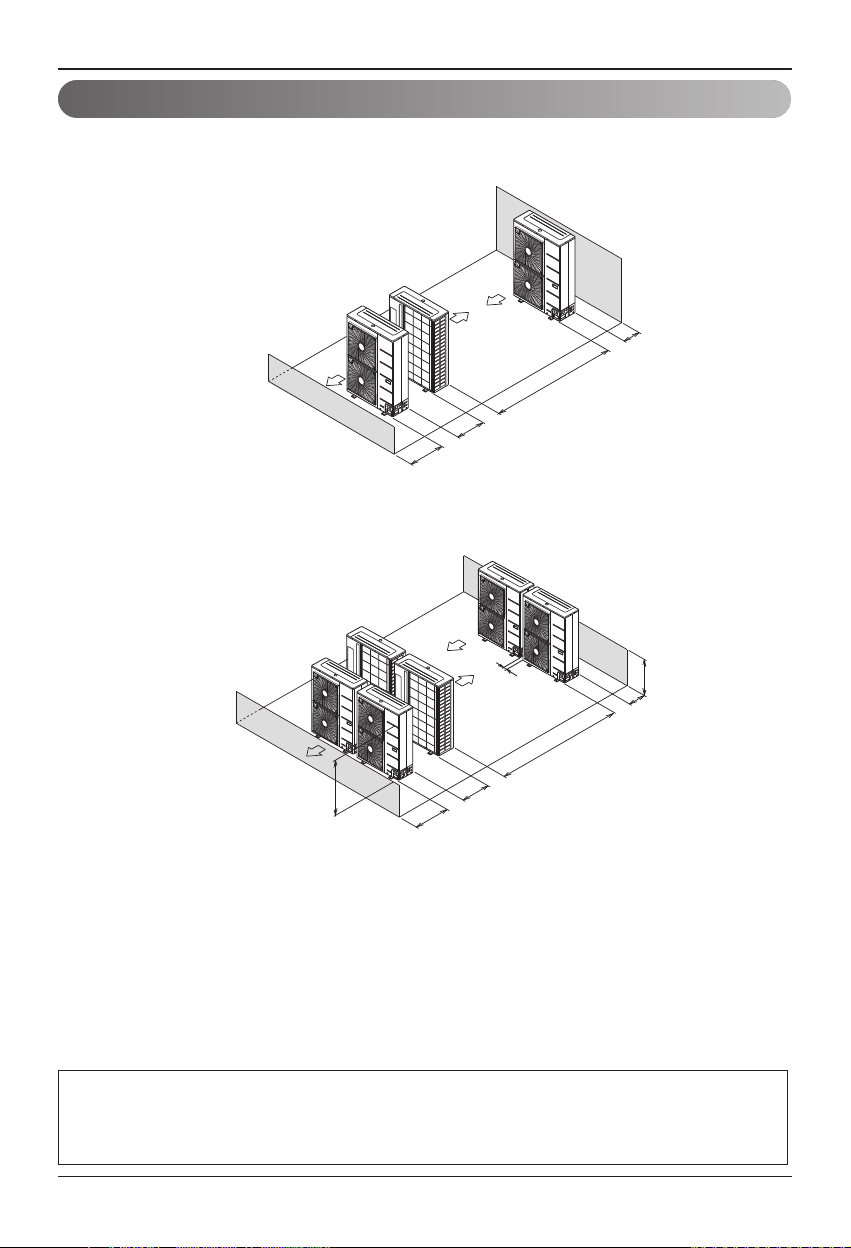
Collective / Continuous Installation for roof top use
Space required for collective installation and continuous installation: When installing several
units, leave space between each block as shown below considering passage for air and people.
1. One row of stand alone installation
2. Rows of collective installation (2 or more)
• L should be smaller than H
L
300 or
more
3000 or
more
H
600 or
more
1500 or
more
100 or
more
L ≤ H
[Unit:mm]
100 or
more
2000 or
more
200 or
more
1000 or
more
[Unit:mm]
Seasonal wind and cautions in winter
• Sufficient measures are required in a snow area or severe cold area in winter so that product can be operated well.
• Get ready for seasonal wind or snow in winter even in other areas.
• Install a suction and discharge duct not to let in snow or rain.
• Install the outdoor unit not to come in contact with snow directly. If snow piles up and freezes on the air suction
hole, the system may malfunction. If it is installed at snowy area, attach the hood to the system.
• Install the outdoor unit at the higher installation console by 50cm than the average snowfall (annual average snowfall) if it is installed at the area with much snowfall.
1. The height of H frame must be more than 2 times the snowfall and its width shall not exceed the
width of the product. (If width of the frame is wider than that of the product, snow may accumulate)
2. Don't install the suction hole and discharge hole of the Outdoor Unit facing the seasonal wind.
Installation
Installation Manual 17
ENGLISH
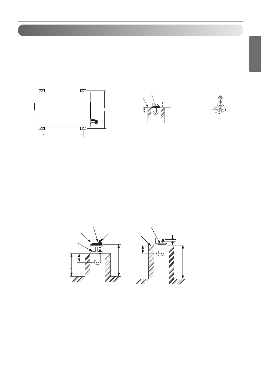
Foundation for Installation
• Fix the unit tightly with bolts as shown below so that the unit will not fall down due to earthquake.
• Noise and vibration may occur from the floor or wall since vibration is transferred through the installation part depending on installation status. Thus, use anti-vibration materials (cushion pad)
fully (The base pad shall be more than 200 mm (7-7/8 inch)).
1) Indoor Unit
2) Outdoor Unit
• Check the strength and level of the installation ground so that the unit will not cause any
operating vibration or noise after installation.
• Fix the unit securely by means of the foundation bolts. (Prepare 4sets of M12 foundation
bolts, nuts and washers each which are available on the market.)
• It is best to screw in the foundation bolts until their length are 20mm from the foundation
surface.
Anti-vibration material
354
Concrete
base
Support
75
3 or more screw
threads of the
2 bolts must be
shown
Nut
Spring washer
Flat washer
Anchor bolt
392
(Unit: mm)
Anti-vibration
Concrete
base
materials
75
Four bolt are
required
3 thread ridges
200
[Unit:mm]
Frame
H-Beam
100
Spring washer
Nut
75
200
Foundation bolt executing method

Installation
18
General Considerations
Followings should be considered before beginning water circuit connection.
• Service space should be secured.
• Water pipes and connections should be cleaned using water.
• Space for installing external water pump should be provided.
• Never connect electric power while proceeding water charging.
Water Piping and Water Circuit Connection
While installing water pipes, followings should be considered :
•
While inserting or putting water pipes, close the end of the pipe with pipe cap to avoid dust entering.
• When cutting or welding the pipe, always be careful that inner section of the pipe should not be
defective. For example, no weldments or no burrs are found inside the pipe.
• Pipe fittings (e.g. L-shape elbow, T-shape tee, diameter reducer, etc) should be tightened
strongly to be free from water leakage.
• Connected sections should be leakage-proof treatment by applying tefron tape, rubber bushing,
sealant solution, etc.
• Appropriate tools and tooling methods should be applied to prevent mechanical breakage of the
connections.
• Operation time of flow valve(e.g. 3way valve) should be less than 90 seconds.
• Pipe is insulated to prevent heat loss to external environment.
Water Piping and Water Circuit Connection
Installation
Installation Manual 19
ENGLISH
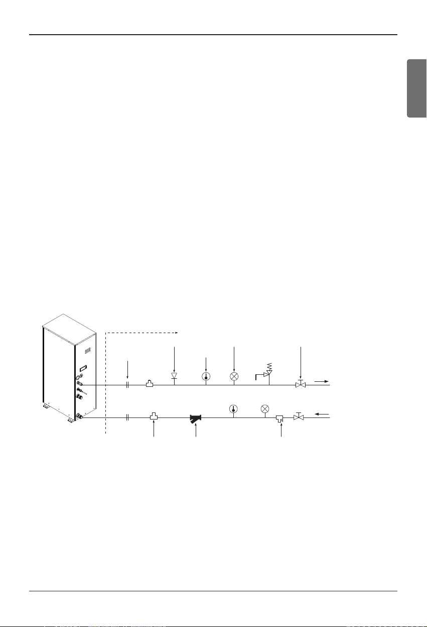
Water cycle
* For the water pipe system, use the closed loop type.
1. For the parts of the water pipe system, use the parts above the design water pressure.
2. For the water pipe, do not use steel pipe.
3. To replace the connected device easily, install the union joint (2).
4.
Install the service port (3) to clean the heat exchanger at each inlet and outlet of the water pipe.
5. Always install a strainer (4) at the inlet of the water pipe.
- For the strainer, use one with 50 mesh or above with measurement diameter of 0.4mm or
less. (Exclude other net)
- Always install the strainer on the horizontal pipe.
(When dirt, trash, rusted pieces get into the water pipe system, it can cause problems to the
product by corroding the metallic material.)
6. Install the air vent (5) at the top of the water pipe.
7. Install a thermometer (6) and pressure gauge (7) at the inlet and outlet of the water pipe.
8. Install the drain valve (8) that can be used for draining the water inside when replacing the part
or providing service.
9. Install the shut-off valve (9) to block the water by closing the valve when replacing the part or
cleaning.
10. Apply insulated treatment on the exterior of the water pipe so that water drops do not form.
11. Install excessive pressure safety valve (10) that meets the design water pressure to prevent
unit or water pipe damage at the pressure increase inside the water pipe system.
12. There is a drain hole at the bottom of prevent risk of electric shock caused by leakage of
water.
On-site installation (1)
Air vent (5)
Union joint (2) Thermometer (6) Excessive pressure
Pressure gauge(7) Shut-off valve (9)
safety valve(10)
Outlet Water
[Install water tank]
or
[Install floor heating]
Inlet water
Drain valve(8)Strainer(4)P/T Service port(3)
Installation
20
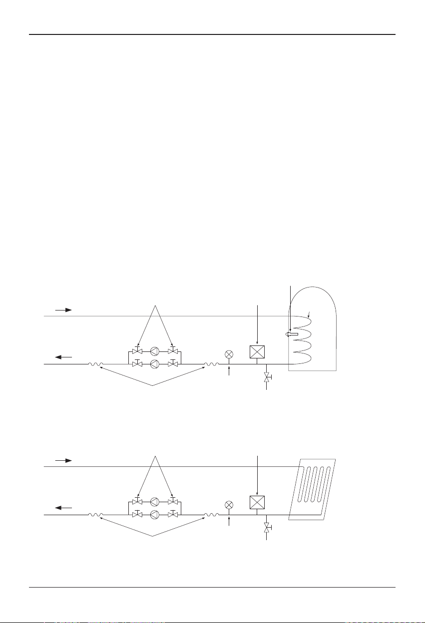
* Water tank & Floor heating installation
1. Use the pump (1) with sufficient capacity to assure loss of overall water pressure and to supply
water to the Indoor Unit.
2. Install the shut-off valve (2) on both sides of the pump to clean and repair the pump.
3. Install the flexible joint (3) to prevent noise and vibration transferred from the pump.
4. Install the pressure gauge (4) to monitor the water pressure from water tank. (Option)
5. Install the expansion tank (5) to accommodate the water contracted or expanded from the temperature difference and to supply the water.
6. After the installation of water pipe system is completed, open the water supply valve (6) and supply the water.
7. When installing the water tank, insert the water tank temperature sensor (7) to measure the temperature of the water inside the tank.
- For the water tank temperature sensor, use the sensor supplied on the product.
- When heating the floor, measure the temperature by using the remote controller or remote tem-
perature sensor (Separately sold).
8. Use the water tank (9) with the heat exchange coil (8) installed so that the heat can be exchanged
sufficiently inside the tank.
Installation of water tank
Installation of floor heating
water tank
temperature sensor (7)
shut-off valve (2)
Expansion tank (5)
Heat
exchange
coil (8)
Pump (1)
Flexible joint (3)
shut-off valve (2)
Pump (1)
Flexible joint (3)
Pressure gauge (4)
Water supply valve (6)
Expansion tank (5)
Pressure gauge (4)
Water supply valve (6)
water tank (9)
(Indirect heating type)
Floor heating coil
(Radiator, FCU can be used)
Installation
Installation Manual 21
ENGLISH
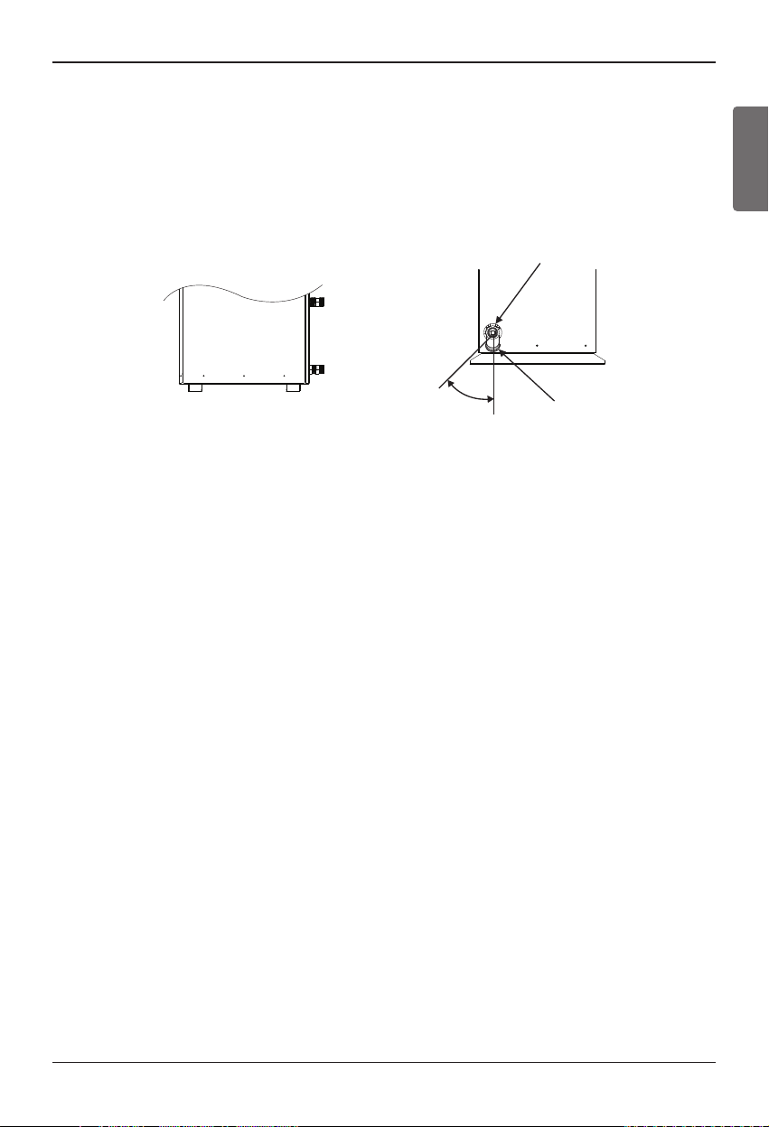
Strainer
- Use the 50 mesh strainer.
(Exclude scale diameter of 0.4mm or less and other net)
- Check the strainer direction and assemble on the inlet hole (Refer to picture)
- Wrap the Teflon tape on the screw thread of the water pipe for more than 15 times for assembly.
- Install the service port facing downward. (Within left/right 45 degrees)
- Check if there is any leakage on the connecting part.
- Clean the strainer periodically. (Once a year or more frequent)
Water In
45°
Strainer
Front Side
Installation
22
Installation Condition
Installing sanitary water tank requires following considerations :
• Sanitary water tank should be located at the flat place.
• Water quality should comply with EN 98/83 EC Directives.
• As this water tank is sanitary water tank (indirect heat exchange), do not use anti water-freezing
treatment like ethylene grycol.
• It is highly recommend to wash out inside of the sanitary water tank after installation. It ensures
generating clean hot water.
• Near the sanitary water tank, there should be water supply and water drain for easy access and
maintenance.
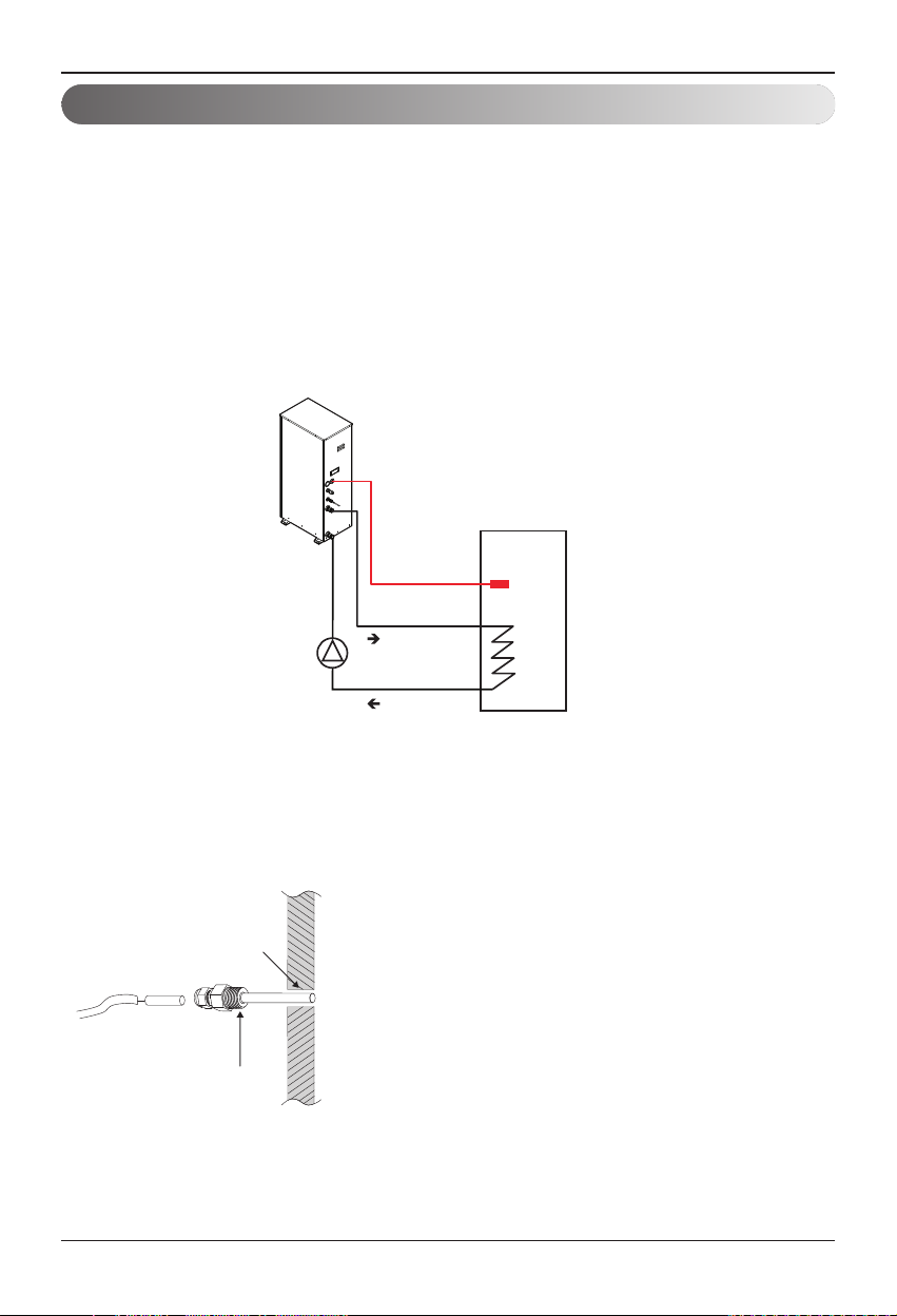
Sanitary Water Tank and Sanitary Water Tank Kit
Sanitary
Water Tank
Water Tank
Temperature Sensor
Water In
Water Out
PT 1/2 inch
Process PT 1/2 inch
female bolt
Inside water tank
Water tank outer wall
Water Tank
Temperature Sensor
Sensor
holder
• If hot water mode is used, make sure to install
sensor to water tank.
• Make PT15A female bolt hole in the water tank,
and install sensor in the water tank.
• Push the sensor into the hole of the sensor holder
cap.
• Lock the sensor holder cap.
Water tank temperature sensor connection
 Loading...